

Page 1

OPERATOR MANUAL
for the
Publication No. 990601
January 1996
Supersedes 990601
August 1993
Kodak X-Omatic
MODELS 4, 4L, and 4SL
IDENTIFICATION CAMERA
© Eastman Kodak Company
Page 2

PLEASE NOTE The information contained herein is based on the experience and knowledge relating to the
subject matter gained by Eastman Kodak Company prior to publication.
No patent license is granted by this information.
Eastman Kodak Company reserves the right to change this information without notice, and
makes no warranty, express or implied, with respect to this information. Kodak shall not be liable
for any loss or damage, including consequential or special damages, resulting from any use of
this information, even if loss or damage is caused by Kodak’s negligence or other fault.
This equipment includes parts and assemblies sensitive to damage from electrostatic
discharge. Use caution to prevent damage during all service procedures.
Table of Contents
Description Page
Operator Orientation . . . . . . . . . . . . . . . . . . . . . . . . . . . . . . . . . . . . . . . . . . . . . . . . . . . . . 3
Product Description . . . . . . . . . . . . . . . . . . . . . . . . . . . . . . . . . . . . . . . . . . . . . . 3
Operator Controls . . . . . . . . . . . . . . . . . . . . . . . . . . . . . . . . . . . . . . . . . . . . . . . 4
Normal Operation . . . . . . . . . . . . . . . . . . . . . . . . . . . . . . . . . . . . . . . . . . . . . . . . . . . . . . . 5
Applying Power to the ID CAMERA . . . . . . . . . . . . . . . . . . . . . . . . . . . . . . . . . 5
Setting the Date and Time . . . . . . . . . . . . . . . . . . . . . . . . . . . . . . . . . . . . . . . . . 5
Clearing the Date and Time . . . . . . . . . . . . . . . . . . . . . . . . . . . . . . . . . . . . . . . 5
Recording Patient Data . . . . . . . . . . . . . . . . . . . . . . . . . . . . . . . . . . . . . . . . . . . 5
Making an Exposure . . . . . . . . . . . . . . . . . . . . . . . . . . . . . . . . . . . . . . . . . . . . . 7
Adjusting Exposure and Film Image Density . . . . . . . . . . . . . . . . . . . . . . . . . . . . . . . . . . 9
If Image is Too Light . . . . . . . . . . . . . . . . . . . . . . . . . . . . . . . . . . . . . . . . . . . . . 9
If Image is Too Dark . . . . . . . . . . . . . . . . . . . . . . . . . . . . . . . . . . . . . . . . . . . . . 10
Troubleshooting Procedures . . . . . . . . . . . . . . . . . . . . . . . . . . . . . . . . . . . . . . . . . . . . . . . 11
Troubleshooting Chart . . . . . . . . . . . . . . . . . . . . . . . . . . . . . . . . . . . . . . . . . . . . 11
Error Code Table . . . . . . . . . . . . . . . . . . . . . . . . . . . . . . . . . . . . . . . . . . . . . . . . 12
New Equipment Warranty . . . . . . . . . . . . . . . . . . . . . . . . . . . . . . . . . . . . . . . . . . . . . . . . . 13
Publication History . . . . . . . . . . . . . . . . . . . . . . . . . . . . . . . . . . . . . . . . . . . . . . . . . . . . . . 15
2 January 1996 – 990601
Page 3

Operator Orientation
Section 1: Operator Orientation
Product Description
The
Kodak X-Omatic
hereon), records patient identification data onto x-ray film in lighttight CASSETTES.
The ID CAMERA provides:
• Dual lenses for use with C-1 and C-1N windows for MODELS 4 and 4L
• Excellent image quality due to high-quality lenses
• Operation in normal room illumination
• The exact time and date of the exposure recorded on the film with customizable date and time formats
• The serial number of the camera is recorded on the film by all models in all lens positions except the C-1N lens
position on the MODEL 4SL.
• Choice of both anterior-posterior (A-P) and posterior-anterior (P-A) imaging
• MODEL 4 records patient data on the upper corner of the film
• MODELS 4L and 4SL records patient data on the lower corner of the film
Environmental Requirements
The ID CAMERA will operate in the ambient room conditions normally encountered in an x-ray department:
• 15˚C to 30˚C (59˚F to 86˚F)
• 15% to 76% Relative Humidity
IDENTIFICATION CAMERA, MODELS 4, 4L, and 4SL (referred to as the ID CAMERA from
Cassettes
The ID CAMERA will function with the following CASSETTES:
• All sizes of
• All sizes of
• All sizes of
Power Requirements
BothMODELSwilloperatecorrectlyfrom100to240VACat50or60Hz. MODELS 4 and 4L come presettooperate
on 120 V AC. Each ID CAMERA is internally switchable to operate on any of the following voltage ranges:
•Donot connect the ID CAMERA to a power source that serves other equipment.
• Check that the ID CAMERA is connected to an outlet with a reliable earth ground.
• Use the correct FUSE for your current.
Kodak X-Omatic
Kodaflex
CASSETTES with C-1 windows
Kodak Min-R
Model
4, 4L, and 4SL 50 or 60 220 TUV 1 A
CASSETTES with C-1 windows
2 CASSETTES with C-1N windows
Frequency
(Hz) V AC 10% Fuse
50 or 60 100 UL/CSA 3 A
50 or 60 120 UL/CSA 3 A
50 or 60 230 TUV 1 A
50 or 60 240 TUV 1 A
990601 – January 1996 3
Page 4
OPERATORS MANUAL
H139_0002AC
BUTTON
POWER
P-A CARD SLOT
A-P
CARD
SLOT
H139_0002ACA
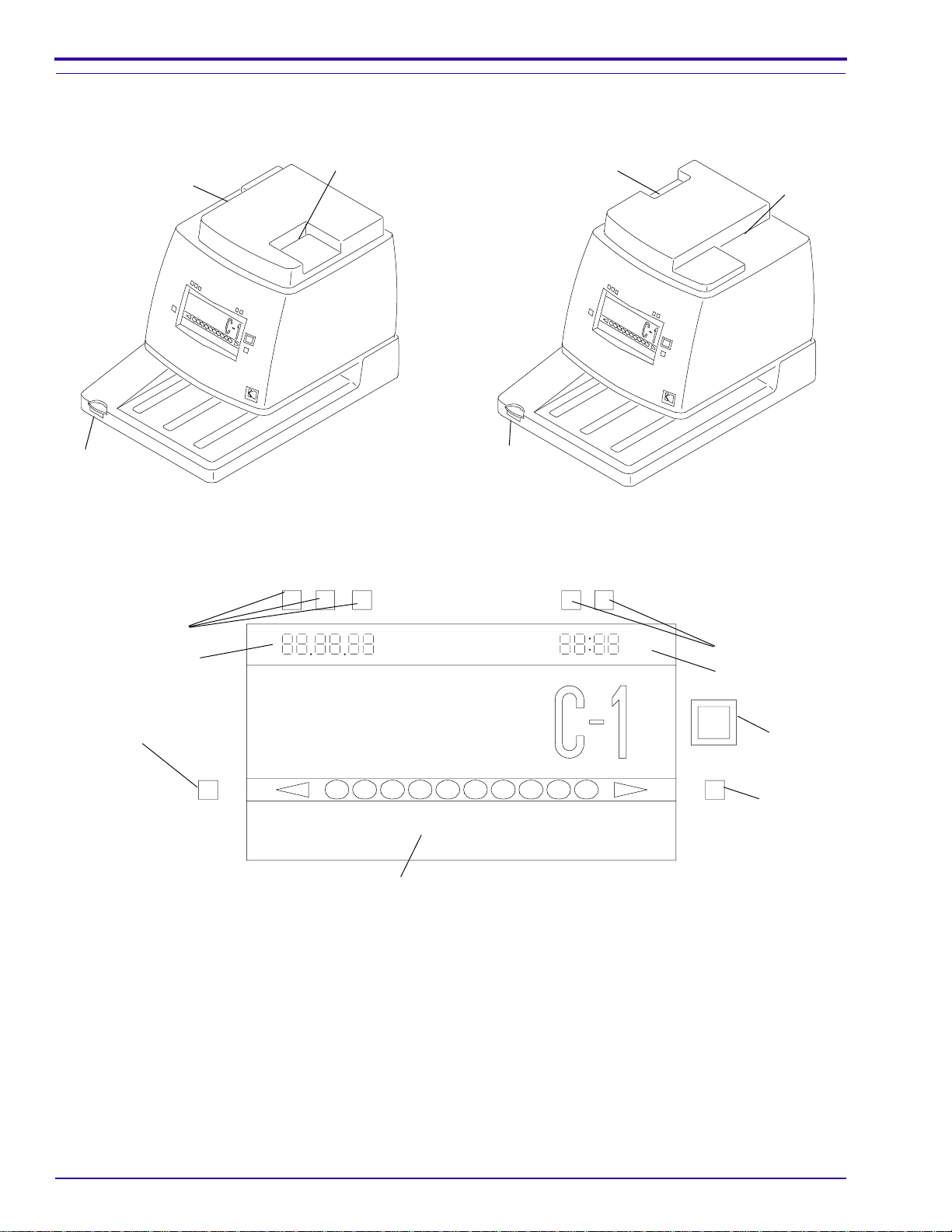
Operator Controls
Figure 1 Model 4
P-A CARD
A-P CARD SLOT
POWER
BUTTON
SLOT
H139_0001ACA
H139_0001AC
Figure 3 Operator Controls for the ID Camera
Figure 2 Model 4L and 4SL
DATE BUTTONS
DATE DISPLAY
DENSITY
DECREASE
BUTTON
1
LCD PANEL
PM
TIME BUTTONS
TIME DISPLAY
WINDOW
BUTTON
2
4
3
8
765
10
9
DENSITY
INCREASE
BUTTON
H139_0003BCA
H139_0003BC
4 January 1996 – 990601
Page 5

Normal Operation
Section 2: Normal Operation
Applying Power to the ID CAMERA
[1] Check that the ID CAMERA is connected to an outlet with a reliable earth ground.
[2] Press the POWER BUTTON to energize the ID CAMERA.
Setting the Date and Time
Note
The date and timeformatsfor your country aresetby the installer at timeof installation. Changesto the date or time
formats require you to contact Kodak service.
[1] Check that the date and time are displayed correctly on the LCD PANEL on the ID CAMERA. See Figure 3.
[2] If necessary, change the date and time.
(a) Press the DENSITY INCREASE andDENSITY DECREASE BUTTONS at the same time. The values in
the DATE and TIME DISPLAYS will flash.
(b) Press the DATE BUTTONS to select the date you want. The DATE BUTTONS are programmed to the
date format for your country.
• For example, if your date format is month/day/year, the left BUTTON controls the month, the middle
BUTTON controls the day, and the right BUTTON controls the year.
• If your date format is day/month/year, the left BUTTON controls the day, the middle BUTTON controls
the month, and the right BUTTON controls the year.
• Ifyourdateformatisyear/month/day,the left BUTTON controls theyear,the middle BUTTON controls
the month, and the right BUTTON controls the day.
(c) Continue to press the appropriate DATE BUTTONS until thecorrect date is displayed on theLCD PANEL.
(d) PresstheTIME BUTTONStoselectthe time you want.TheTIMEBUTTONS areprogrammedto your time
format, either a 12- or 24-hour clock. In both the 12- and 24-hour time formats, the left TIME BUTTON
controls the hour, and the right TIME BUTTON controls the minutes.
(e) Continue to press the TIME BUTTONS until the correct time is displayed on the LCD PANEL.
(f) Press the DENSITY INCREASE BUTTON only, approximately 2 - 3 seconds, until the DATE and TIME
DISPLAYS stop flashing.
Note
• The DENSITY BUTTONS are deactuated while the DATE and TIME DISPLAYS are flashing.
• The time or date cannot be changed if a PATIENT ID CARD is in either the P-A or A-P CARD SLOT.
(g) Check that the density setting is correct. If necessary, change the density setting.
Clearing the Date and Time
To clear the date and time, or set the date and time to “0”, de-energize the CAMERA, press the DENSITY
DECREASE BUTTON, and then press the POWER BUTTON. This clears, or resets, the microprocessor.
Recording Patient Data
[1] Prepare a patient IDENTIFICATION CARD for a CASSETTE that has exposed but unprocessed x-ray film.
[2] See the following list and illustration for the specifications of the IDENTIFICATION CARD.
• Minimum size: 15.24 x 5.72 cm (6 x 21⁄4 in.)
990601 – January 1996 5
Page 6

OPERATORS MANUAL
• Maximum size:
small slot - 8.25 cm x 15.24 cm (31⁄4 x 6 in. or longer)
large slot - 21 cm x 28 cm (8.1⁄2 x 11 in.)
• Maximum thickness: 0.305 mm (0.012 in.)
• Minimum thickness: 0.102 mm (0.004 in.)
• Required Card Color: Dull white with black ink
Note
• Standard white tab or Recommended Patient ID Cards with rounded corners are ideal.
• The dimensions of these cards are 8.3 X 18.7 cm (31⁄4 x 73⁄8 in.).
• If the ink is not
black
, the density of the patient data on the film might not be correct.
Important
Bent or damaged white tab or data cards might affect patient data on the film.
Figure 4 Recommended Patiend ID Card for Models 4, 4L, and the 4SL in the C-1 lens position
4 mm (5/32 in.)
2.4 cm (15/16 in.)
6.6 cm (2 19/32 in.)
8.3 cm (3 1/4 in.)
1.27 mm
(0.050 in.)
18.7 cm (7 3/8 in.)
Typical Data Card Dull White Preferred
Figure 5 Recommended Patient ID Card for Model 4SL in the C1N lens position
4 mm (5/32 in.)
Typical Data Card Dull White Preferred
0.2 mm
(0.007 in.)
thick
H139_0064BC
1.5 cm (19/32 in.)
8.3 cm (3 1/4 in.)
6.6 cm (2 19/32 in.)
1.27 mm
(0.050 in.)
18.7 cm (7 3/8 in.)
0.2 mm
(0.007 in.)
thick
H139_0079BC
6 January 1996 – 990601
Page 7

Making an Exposure
H139_0005AC
SLOT
P-A CARD
H139_0005ACA
H139_0007AC
SLOT
P-A CARD
BUTTON
WINDOW
H139_0007ACA
Normal Operation
Figure 6 Model 4 with A-P Format Selected
Figure 7 Model 4 with P-A Format Selected
A-P
CARD
SLOT
H139_0004ACA
H139_0004AC
[1] Choose the A-P or P-A imaging format by inverting and insertingan IDENTIFICATION CARD in the appropriate
CARD SLOT withpatient information toward the center of the ID CAMERA. You will hear a MOTORmove the
MIRROR when changing from one imaging format to the other. See the illustrations below and check the A-P
or P-A displayed on the LCD PANEL.
Figure 8 Models 4L and 4SL with P-A Format
Selected
A-P CARD SLOT
[2] Choose C-1 WINDOW (for
Kodak X-Omatic
CASSETTES) by pressing the WINDOW BUTTON. The LCD PANELwill displaythe WINDOW format chosen
for the exposure.
WINDOW
BUTTON
H139_0006ACA
H139_0006AC
and
Figure 9 Models 4L and 4SL with A-P Format
Selected
Kodaflex
CASSETTES), or C-1N WINDOW (for
Min-R
2
990601 – January 1996 7
Page 8

OPERATORS MANUAL
Figure 10 Inserting a Cassette
THICK SECTION
OF BASE
SLOT
H139_0008ACA
H139_0008AC
[3] Place a CASSETTE loaded with exposed film on the BASE with the WINDOW in the top left corner.
[4] Keep the left side of the CASSETTE flush with the THICK SECTION of the BASE.
Important
Do not move the CASSETTE during the exposure.
[5] Insert the CASSETTE fully into the SLOT above the BASE.
Note
The entire exposure cycle takes approximately 2 seconds. When you insert a CASSETTE correctly into the SLOT
above the BASE, the ID CAMERA automatically:
• Actuates a mechanical ARM to open the WINDOW in the CASSETTE.
• Illuminates a LAMP to record the identification data, time, date, serial number, and A-P/P-A data on the film.
• Closes the WINDOW in the CASSETTE.
[6] Remove the CASSETTE from the CAMERA after the CAMERA beeps.
[7] Process the film according to the manufacturer's specifications.
8 January 1996 – 990601
Page 9

Adjusting Exposure and Film Image Density
Section 3: Adjusting Exposure and Film Image Density
If Image is Too Light
Figure 11 Adjusting the Density Setting
PM
DENSITY
DECREASE
BUTTON
2
1
4
3
8
765
10
9
DENSITY
INCREASE
BUTTON
DENSITY SETTING DISPLAY
LCD DISPLAY
H139_0003BCB
H139_0003BC
[1] Press the DENSITY INCREASE BUTTON toincrease the exposure and darken the densityof theimage on the
film.
Important
Only the DENSITYSETTING selected willbe displayed on the LCD. The other settingswill appear asblack circles.
Figure 10 shows all the settings to help orient you to the way the DENSITY BUTTONS work, showing the range of
settings from 1 (lightest) to 10 (darkest). The DENSITY INCREASE BUTTON features “wrap around” DENSITY
SETTINGS. If you press the DENSITY INCREASE BUTTON after Setting 10 is selected, Setting 1 willbe selected
next, decreasing the density.
Note
Youcanusethe smallest size cassette available when adjusting exposure toreducethecost of film consumed during
this procedure.
[2] Load the CASSETTE with film.
[3] Record the DENSITY SETTING on the ID CARD.
[4] Expose the CASSETTE and process the film.
[5] Repeat Steps 2 through 4, if necessary. Compare the images andselect the best DENSITY SETTING. Record
the DENSITY SETTING selected, for future reference.
990601 – January 1996 9
Page 10

OPERATORS MANUAL
If Image is Too Dark
[1] Press the DENSITY DECREASE BUTTON to decrease the exposure and to lightenthe density ofthe image on
the film.
[2] Load the CASSETTE with film.
[3] Record the DENSITY SETTING on the ID CARD.
[4] Expose the CASSETTE and process the film.
[5] Repeat Steps 2 through 4, if necessary. Compare the images and select the best one. Record the DENSITY
SETTING selected, for future reference.
10 January 1996 – 990601
Page 11

Troubleshooting Procedures
Section 4: Troubleshooting Procedures
Troubleshooting Chart
MALFUNCTION POSSIBLE PROBLEM ACTION
ID CAMERA does not
energize
ID CAMERA does not
operate with a
CASSETTE inserted
Cassette window unable
to open
Time is not correct The CLOCK is not set correctly Set the CLOCK to the correct time. See the
Patient data is too dark
or too light
Patient data is out of
focus
ID CAMERA has no power:
• POWER CORD is damaged Order a new POWER CORD.
• ID CAMERA is unplugged Plug in ID CAMERA.
• FUSE is blown Call local service.
• CIRCUIT BREAKER tripped Check for power at outlet.
CASSETTE is not inserted
correctly
SWITCH is out of adjustment. Call local service.
DATE and TIME DISPLAYS are
flashing
CASSETTE is damaged Try a different CASSETTE.
DENSITY SETTING is not set
correctly
The ID CARD moved during the
exposure
1. Insert the CASSETTE fully to the back of
the ID CAMERA.
2. Check that the:
• CASSETTE Window is facingup.
• Left side of the CASSETTE is flush with
the THICK SECTIONon the leftside of
the BASE. See the figure on Page 8.
Check the date and time:
• If correct, press and hold the DENSITY
INCREASEBUTTONuntil the display stops
flashing, approximately 2-3 seconds.
• If not correct, see “Setting the Date and
Time” on page 5.
“Setting Date and Time” procedure on Page 5
in this manual.
1. UsetheDENSITY DECREASE BUTTON to
lighten the data or the DENSITY
INCREASE BUTTON to darken the data.
2. Make another exposure and repeat Step 1.
3. If this does not correct the problem,send in
forservice.Seethewarrantyinformationon
Page 13 for the address.
1. Repeat the exposure and be sure that the
ID CARD does not move during the
exposure.
2. If this does notcorrect the problem, contact
the local service representative or send in
for service. See the Warranty on Page 13.
990601 – January 1996 11
Page 12

OPERATORS MANUAL
Error Code Table
ERROR CODE POSSIBLE MALFUNCTION ACTION
E1 No Card in either A-P or P-A Slot Remove the CASSETTE and put an ID CARD in
either the A-P or P-A Slot.
E2 LAMP Failure or FUSE blown or missing. Contact the local service representative or send
in for service.
E3 Cassette Window Failed to Open Remove the CASSETTE and try a different
CASSETTE.
E4 ID CAMERA Failed to Shift to A-P Position
Correctly
E5 ID CAMERA Failed to Shift to P-A Position
Correctly
E6 ID CAMERA Failed to Change Lens
Mechanism Correctly
Contact the local service representative or send
in for service.
Contact the local service representative or send
in for service.
Contact the local service representative or send
in for service.
12 January 1996 – 990601
Page 13

Section 5: New Equipment W arranty
New Equipment Warranty
Kodak warrants the
one year from date of initial installation, when installed within one year from the date of shipment.
Warranty Repair Coverage
If this equipment does not function properly during the warranty period, Kodak provides repair service which will
includeanynecessary adjustments and/or replacement of partsandreturnshipping costs necessary to maintain your
equipment in good working order.
How to Obtain Service
Should equipment require service, repack equipment in its original packaging and return it to the Reconditioning
Center. If you do not have the original packaging, you can order replacement packaging Part No. 699725. See the
form entitled “Repair Program for KODAK X-OMATIC Identification Camera, Models 4,4L, and 4SL” included behind
the “MISCELLANEOUS” tab in this binder. If the camera is under warranty, contact your Kodak Account Manager.
Limitations
This warranty does not cover: circumstances beyond Kodak's control; misuse; abuse; any attachments, accessories,
or alterations not marketed by Kodak (including service or parts to correct problems resulting from the use of such
attachments, accessories or alterations); failure to follow Kodak's operating instructions; or supply items.
Kodak makes no other warranties, express, implied, or of merchantability for this equipment.
Repair without charge is Kodak's only obligation under this warranty.
•
Kodak will not be responsible for any consequential or incidental damages resulting from the sale, use, or
Kodak X-Omatic
IDENTIFICATION CAMERA, MODELS 4, 4L,and 4SL to operate correctly for
improperfunctioning of this equipment even if loss or damage is caused by the negligence or other fault of Kodak.
• Such damages for which Kodak will not be responsible, include, but are not limited to, loss of revenue or profit,
downtime costs, loss ofuse ofthe equipment, cost ofany substituteequipment, facilities or servicesor claimsof
your customers for such damages.
This limitation of liability will not apply to claims for injury to persons or damage to property caused by the sole
negligence or fault of Kodak or by persons under its direction or control.
990601 – January 1996 13
Page 14

OPERATORS MANUAL
This page is intentionally blank.
14 January 1996 – 990601
Page 15

Section 6: Publication History
Print Date Pub. No. ECO No. Affected Pages File Name Notes
August 1993 990601 All Pages 3294cm_a.doc First printing.
January
1996
990601 2504-435 All Pages om3294_1_435.doc Added 4SL information.
Publication History
990601 – January 1996 15
Page 16

Kodak, Kodaflex, Min-R,
and
X-Omatic
are trademarks.
om3294_1.fm
Printed In USA
Health Imaging
EASTMAN KODAK COMPANY ● ROCHESTER, N.Y. 14650
 Loading...