

Kodak X-Omat Clinic 1, X-Omat M43 User manual
Publication No. 981094
September 1995
Supersedes
October 1994
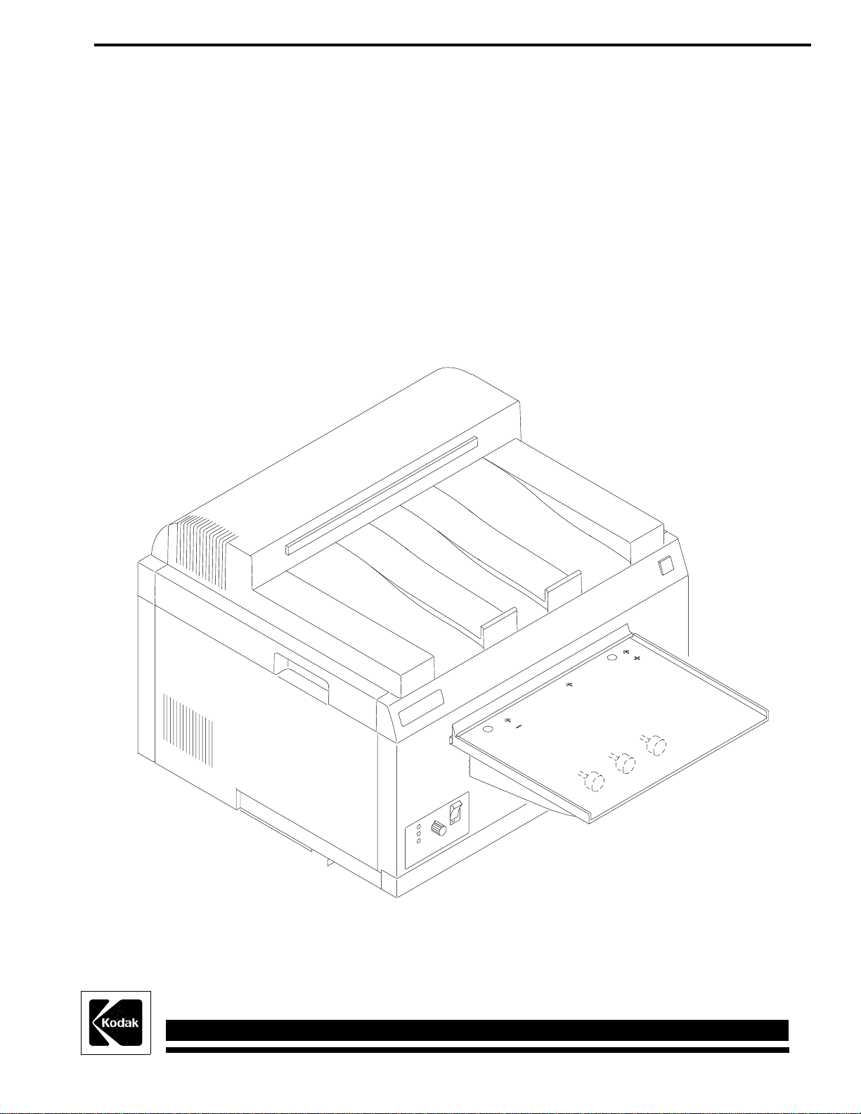
COMPONENT LOCATOR for the
Kodak X-Omat M43 and M43A PROCESSORS
and the
Kodak X-Omat CLINIC 1 PROCESSOR
HEALTH SCIENCES DIVISION
© Eastman Kodak Company
H130_0009DA

PLEASE NOTE The information contained herein is based on the experience and knowledge relating to the
subject matter gained by Eastman Kodak Company prior to publication.
No patent license is granted by this information.
Eastman Kodak Company reserves the right to change this information without notice, and
makes no warranty, express or implied, with respect to this information. Kodak shall not be
liable for any loss or damage, including consequential or special damages, resulting from any
use of this information, even if loss or damage is caused by Kodak’s negligence or other fault.
This equipment includes parts and assemblies sensitive to damage from electrostatic
discharge. Use caution to prevent damage during all service procedures.
Component Lists . . . . . . . . . . . . . . . . . . . . . . . . . . . . . . . . . . . . . . . . . . . . . . . . . . . . . . . . 3
Alarm - LS . . . . . . . . . . . . . . . . . . . . . . . . . . . . . . . . . . . . . . . . . . . . . . . . . . . . . . . . . . . . 3
Circuit Board - BD . . . . . . . . . . . . . . . . . . . . . . . . . . . . . . . . . . . . . . . . . . . . . . . . . 3
Circuit Breaker - CB. . . . . . . . . . . . . . . . . . . . . . . . . . . . . . . . . . . . . . . . . . . . . . . . 3
Connectors - P/J . . . . . . . . . . . . . . . . . . . . . . . . . . . . . . . . . . . . . . . . . . . . . . . . . . . 3
Electrostatic Discharge - E . . . . . . . . . . . . . . . . . . . . . . . . . . . . . . . . . . . . . . . . . . . 4
Filter - FL . . . . . . . . . . . . . . . . . . . . . . . . . . . . . . . . . . . . . . . . . . . . . . . . . . . . . . . . 4
Fuses - F . . . . . . . . . . . . . . . . . . . . . . . . . . . . . . . . . . . . . . . . . . . . . . . . . . . . . . . . . 4
Heater - HR. . . . . . . . . . . . . . . . . . . . . . . . . . . . . . . . . . . . . . . . . . . . . . . . . . . . . . . 4
Integrated Circuits - U . . . . . . . . . . . . . . . . . . . . . . . . . . . . . . . . . . . . . . . . . . . . . . 4
LED/Indicators - DS. . . . . . . . . . . . . . . . . . . . . . . . . . . . . . . . . . . . . . . . . . . . . . . . 4
Motors - B . . . . . . . . . . . . . . . . . . . . . . . . . . . . . . . . . . . . . . . . . . . . . . . . . . . . . . . 4
Power Supply - A . . . . . . . . . . . . . . . . . . . . . . . . . . . . . . . . . . . . . . . . . . . . . . . . . . 4
Resistors - R
. . . . . . . . . . . . . . . . . . . . . . . . . . . . . . . . . . . . . . . . . . . . . . . . . . . . . . . 5
Sensors/Switches - S. . . . . . . . . . . . . . . . . . . . . . . . . . . . . . . . . . . . . . . . . . . . . . . . 5
Solenoids/Inductors - L. . . . . . . . . . . . . . . . . . . . . . . . . . . . . . . . . . . . . . . . . . . . . . 5
Solid State Relays - SSR. . . . . . . . . . . . . . . . . . . . . . . . . . . . . . . . . . . . . . . . . . . . . 5
Terminal Blocks - TB . . . . . . . . . . . . . . . . . . . . . . . . . . . . . . . . . . . . . . . . . . . . . . . 5
Thermistors - RT . . . . . . . . . . . . . . . . . . . . . . . . . . . . . . . . . . . . . . . . . . . . . . . . . . 5
Transformer - T. . . . . . . . . . . . . . . . . . . . . . . . . . . . . . . . . . . . . . . . . . . . . . . . . . . . 5
2 September 1995 – 981094

Component Lists
Alarm - LS
Page
LS1 Audio Alarm.......................................................................................................7
Circuit Board - BD
Page
BD 100 Circuit Board .................................................................................................8, 9
Circuit Breaker - CB
Page
CB1 Main Power........................................................................................................7
Connectors - P/J
Page
P/J1 Drive Motor Assembly 50/60 Hz Connectors....................................................7
P/J2 Developer Recirculation Pump ..........................................................................6
P/J3 Fixer Recirculation Pump ..................................................................................6
P/J4 Dryer Heater.......................................................................................................6
P/J5 Dryer Blower Motor...........................................................................................6
P/J6 Wash Pump ........................................................................................................6
P/J7 Developer Fixer Replenishment Pump ..............................................................7
P/J8 Developer Heater Assembly ..............................................................................6
P/J12 Status Indicators...............................................................................................7
P/J13 Audio Alarm.....................................................................................................7
P/J14 Film Sensor (-) .................................................................................................7
P/J15 Film Sensor ......................................................................................................7
P/J16 Film Sensor (+) ................................................................................................7
P/J18 Developer Thermistor Assembly .....................................................................7
P/J19 Dryer Thermistor Assembly.............................................................................6
P/J20 Diverter Cooling Solenoid (L2) for M43 and M43A only...............................6
P/J21 Diverter Wash Solenoid (L3) for M43 and M43A only ..................................6
P/J22 Water Input Solenoid .......................................................................................7
P/J24 Developer Temperature Display, M43 and M43A only ..................................7
P/J25 Developer Temperature Display, M43 and M43A only ..................................7
P/J26 Dryer Air Vane Switch at the Harness.............................................................6
J27 Dryer Air Vane Switch at the Switch..................................................................6
P/J28 DC Interlock Switch Connector.......................................................................6
J101 DC Power ..........................................................................................................9
J102 20 Volts AC.......................................................................................................9
J103 Solenoids ...........................................................................................................9
J104 Developer and Dryer Thermistors and Dryer Potentiometer ............................9
J105 Alarm, Indicators, Air Vane Switch, Interlock Switch, and Sensors ................9
981094 – September 1995 3
 Loading...