

Page 1
HEALTH IMAGING
© Eastman Kodak Company, 1999
{OperatorsManual}{Production}{Hea lthImaging}
Publication No. 9B8942
November 1997
Supersedes July 1997
OPERATOR MANUAL
for the
Kodak X-Omat
1000, 1000A, and 1000J
PROCESSORS
Page 2

PLEASE NOTE The information contained herein is based on the experience and knowledge relating to the
subject matter gained by Eastman Kodak Company prior to publication.
No patent license is granted by this information.
Eastman Kodak Company reserves the right to change this information without notice, and
makes no warranty, express or implied, with respect to this information. Kodak shall not be liable
for any loss or damage, including consequential or special damages, resulting from any use of
this information, even if loss or damage is caused by Kodak’s negligence or other fault.
Warning
To avoid hazardous conditions, keep floors and floor coverings around your KODAK X-OMAT Processor and
associated drains clean and dry at all times. Any accumulation of fluids from mixing tanks, drain lines, etc, should
be cleaned upimmediately. In the eventof an accumulation of liquid due to backup, overflow, orother malfunctions
of the drain associated with your Processor, disconnect the power to the Processor and call a plumber or other
contractor to correct any problem with the drain. Kodak accepts no responsibility or liability whatsoever for the
serviceability of any drain connected to or associated with a KODAK X-OMAT Processor. Such drains are the sole
responsibility of the customer.
The KODAK X-OMAT Processor must be at least 1.5 m (5 feet) from the patient exposure area.
DIN 1988 Part 4, Drinking Water Supply Systems: The KODAK X-OMAT 1000, 1000A, and 1000J Processors
haveaFreeOutlet(DINPart4.2.1)watersupplyasshowninthefigureonPage9. The Outlet has an inside diameter
of 5 mm and a clearance of 34 mm between the end of the Outlet and the spill-over level of the solution.
Table of Contents
Description Page
Overview . . . . . . . . . . . . . . . . . . . . . . . . . . . . . . . . . . . . . . . . . . . . . . . . . . . . . . . . . . . . . . 3
Operating Instructions . . . . . . . . . . . . . . . . . . . . . . . . . . . . . . . . . . . . . . . . . . . . . . . . . . . . 6
Daily Start-Up. . . . . . . . . . . . . . . . . . . . . . . . . . . . . . . . . . . . . . . . . . . . . . . . . . . . . . . 6
Film Feeding Procedure. . . . . . . . . . . . . . . . . . . . . . . . . . . . . . . . . . . . . . . . . . . . . . . 7
Daily Shutdown of the Processor. . . . . . . . . . . . . . . . . . . . . . . . . . . . . . . . . . . . . . . . 8
Draining and Cleaning the Tanks, in Preparation for Changing the Chemicals or
Storing the Processor for More Than a Week . . . . . . . . . . . . . . . . . . . . . . . . . . . . 9
Replenishment Solutions . . . . . . . . . . . . . . . . . . . . . . . . . . . . . . . . . . . . . . . . . . . . . . . . . 11
Mixing the Developer and Fixer Replenishers . . . . . . . . . . . . . . . . . . . . . . . . . . . . . . 11
Filling the Tanks in the Processor . . . . . . . . . . . . . . . . . . . . . . . . . . . . . . . . . . . . . . . 11
Preventive Maintenance . . . . . . . . . . . . . . . . . . . . . . . . . . . . . . . . . . . . . . . . . . . . . . . . . . 13
Important . . . . . . . . . . . . . . . . . . . . . . . . . . . . . . . . . . . . . . . . . . . . . . . . . . . . . . . . . . 13
Daily Maintenance . . . . . . . . . . . . . . . . . . . . . . . . . . . . . . . . . . . . . . . . . . . . . . . . . . 13
Weekly Maintenance . . . . . . . . . . . . . . . . . . . . . . . . . . . . . . . . . . . . . . . . . . . . . . . . . 13
Monthly Maintenance. . . . . . . . . . . . . . . . . . . . . . . . . . . . . . . . . . . . . . . . . . . . . . . . . 13
Troubleshooting . . . . . . . . . . . . . . . . . . . . . . . . . . . . . . . . . . . . . . . . . . . . . . . . . . . . . 14
Warranty (U.S. only) . . . . . . . . . . . . . . . . . . . . . . . . . . . . . . . . . . . . . . . . . . . . . . . . . . . . . 16
Product Description . . . . . . . . . . . . . . . . . . . . . . . . . . . . . . . . . . . . . . . . . . . . . . 3
Noise Emission Information . . . . . . . . . . . . . . . . . . . . . . . . . . . . . . . . . . . . . . . . 3
Identifying the Parts of the Processor Referred to in this Operator Manual. . . . 3
Note . . . . . . . . . . . . . . . . . . . . . . . . . . . . . . . . . . . . . . . . . . . . . . . . . . . . . . . . . . 16
Warranty Repair Coverage. . . . . . . . . . . . . . . . . . . . . . . . . . . . . . . . . . . . . . . . . 16
How to Obtain Service . . . . . . . . . . . . . . . . . . . . . . . . . . . . . . . . . . . . . . . . . . . . 16
Limitations . . . . . . . . . . . . . . . . . . . . . . . . . . . . . . . . . . . . . . . . . . . . . . . . . . . . . 16
2 November 1997 – 9B8942
Page 3
Section 1: Overview
Product Description
Overview
Model Electrical Requirements
1000 Processor 220/230/240 V AC, 50/60 Hz
1000J Processor 100 V AC, 50/60 Hz
The KODAK X-OMAT 1000, 1000A, and 1000J
Processors are fully automatic table-top, x-ray film
Processors featuring easy installation and
maintenance, reliability, and optimum image quality.
1000A Processor 120 V AC, 50/60 Hz
Noise Emission Information
Operator position full system operating mode:
• Sound Pressure Level54 dB(A)LA
(1)
• Instantaneous Peak Values > or = 130dB(C)None
Sound Power Level65 dB(A)
(1)
Measured in accordance with DIN 45635 in aHemi-Anechoic chamber
(2)
(2)
Not required when the Sound
Pressure Level LA is < 85 dB(A)
Identifying the Parts of the Processor Referred to in this Operator Manual
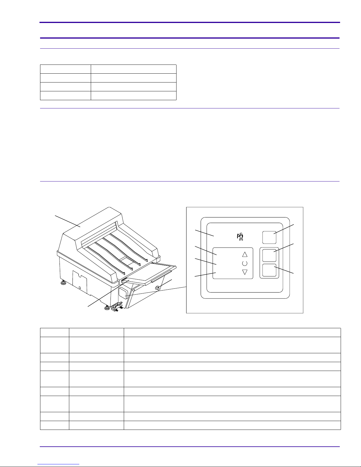
Figure 1 Overall View of the Processor and the Operator Controls
1
4
Service
5
6
7
3
High
Ready
Low
Dev. Temperature
RUN
DEV.
FIX.
Rep.
8
9
10
H164_0026BCA
H164_0026BC
2
Item No. Control Description
3 DryerTemperature
Control Knob
4 “Service” Illuminates when the service provider should be contacted.
5 “High” s Illuminates when the developer temperature is over the setpoint.
6 “Ready” » Illuminates when the developertemperature is correct forprocessing film. It blinks
7 “Low” t Illuminates when the developer temperature is below the setpoint.
8 [ RUN ] Manually starts one processing cycle. Releases the Processor from Standby
9 [ DEV. ] Manually delivers one developer replenishment cycle.
10 [ FIX. ] Manually delivers one fixer replenishment cycle.
9B8942 – November 1997 3
Rotates to adjust the temperature of the air in the Dryer.
when either film is processing or the Wash Tank is filling with water.
Mode.
Page 4
OPERATORS MANUAL
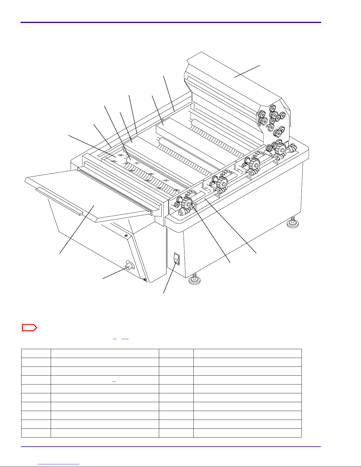
Figure 2 The Processor without the Top Cover
17
16
15
13
14
12
11
2
14
18
19
3
20
H164_0021DCA
H164_0021DC
Note
See also the illustrations on Pages 9 - 11.
Item No. Description Item No. Description
1 Top Cover 17 Dryer Rack
2 Lid of the Feed Tray 18 Drive Shaft
3 - 10 See the table on Page 3. 19 Drive Gear
11 Evaporation Cover 20 “Power” Switch
12 Developer Rack 21 Feed Tray
13 Roller 22 Developer Drain Valve (red)
14 Crossover 23 Fixer Drain Valve (blue)
15 Fixer Rack 24 Developer Drain Hose
16 Wash Rack 25 Fixer Drain Hose
4 November 1997 – 9B8942
Page 5
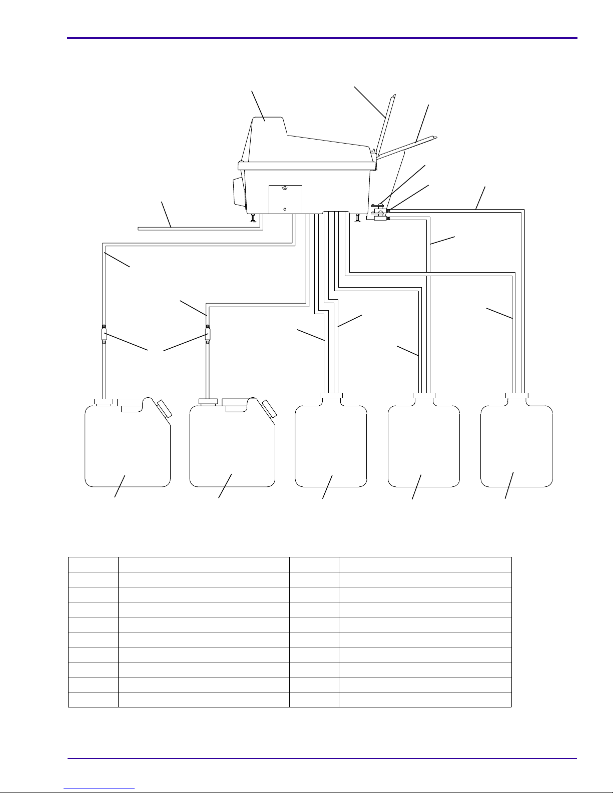
Figure 3 Processor with Replenishment and Drain Hoses Inserted in the Correct Containers
Overview
31
32
33
30
1
2
21
22
23
24
25
28
26
29
27
34 35
H164_0064DCA
H164_0064DC
Item No. Description Item No. Description
26 Developer Overflow Hose 35 Developer Replenishment Container
27 Fixer Overflow Hose 36 Wash Water Drain Container
28 Wash Water Drain Hose 37 Fixer Drain Container
29 Wash Water Overflow Hose 38 Developer Drain Container
30 Developer Replenishment Hose 39 Developer Tank
31 Fixer Replenishment Hose 40 Fixer Tank
32 Replenishment Filter 41 Wash Tank
33 Wash Water Supply 42 Screen Filter
34 Fixer Replenishment Container 43 Pitcher
9B8942 – November 1997 5
36
37
38
Page 6

OPERATORS MANUAL
Section 2: Operating Instructions
Daily Start-Up
Warning
• IfDrainContainers ( 36, 37, 38 ) are used, continually check that the Drain Containers have enough room inthem
to accommodate more solution and will not overflow.
• If the Processor drainssolutions intoa floordrain, thedrain mustbe madeof chemicallyresistant, non-corrosive
material. Use PVC or the equivalent.
• The floor drain must have a minimum diameter of 7.6 cm (3 in.) and be free of obstruction.
• Drain service must comply with all local codes.
• Do not make a solid connection to the floor drain. Use an open floor drain with a minimum clearance of 2.5 cm
(1 in.) between the tubing from the Processor and the sides of the floor drain.
• If the Processor has not been used in a week or more, change the Replenishment Filters ( 32 ) .
[1] Check the solution levels in theReplenishment Containers (34, 35 ) and in the Drain Containers( 36, 37, 38 ) .
(a) If the levels in the ReplenishmentContainers arelow, mix more solutions andadd tothe Containers. See
Page 11.
(b) If the Drain Containers are almost full, replace them with empty Containers.
[2] Remove the TopCover (1)by holding the front and back with both hands andlifting the TopCover straightup.
[3] Check the solution levels in the Developer and Fixer Tanks ( 39, 40 ) in the Processor. (The Tanks are shown
in Figure 6 on Page 10.)
Caution
Even small amounts of one solution can seriouslycontaminate the other andcause poor quality x-ray images. This
is especially true when fixer contaminates the developer. To help avoid contamination, thoroughly rinse the Pitcher
or other Containers before and after each use. Or you may want to have a separate set of implements for the fixer
and for the developer.
(a) If the fixer is low, add more fixer solution to the Fixer Tank ( 40 ) until fixer solution comes out of the
Overflow Hose ( 27 ) .
(b) Check the solution level in the Developer Tank ( 39 ) , and add more developer if necessary.
Note
You can add solution to the Tanks in two ways -by either pouring the appropriate solution from the Pitcher (43)or
pressing [ DEV. ] or [ FIX. ] ( 9 or 10 ) until solution comes out of the Overflow Hose ( 26 or 27 ) .
[4] Close the Top Cover ( 1 ) of the Processor.
[5] Press the four corners of the Top Cover to check that it is closed tightly.
• If the Top Cover is not closed tightly, light will enter the Processor and fog the film, and the Rollers ( 13 )
will not accept film.
[6] Press the “ | ” on the “Power” Switch ( 20 ) to turn the Processor on.
[7] Turn on the water to the Processor.
[8] The “Ready” Light » ( 6 ) will illuminate and a beep will sound when the Processor is ready to process film.
6 November 1997 – 9B8942
Page 7
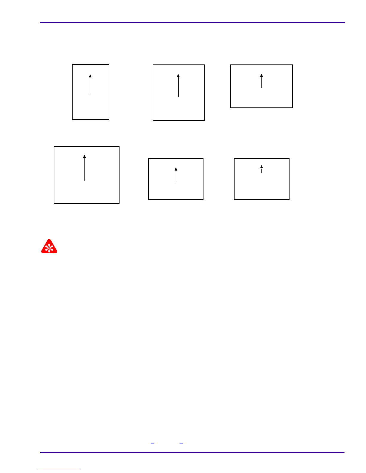
Film Feeding Procedure
Figure 4 Feeding Film into the Processor
Operating Instructions
H164_0019HC
1 each
35 x 43 cm
(14 x 17 in.)
1 each
25 x 30 cm
(10 x 12 in.)
1 each
35 x 35 cm
(14 x 14 in.)
1 each
18 x 25 cm
(8 x 10 in.)
1 each
28 x 35 cm
(11 x 14 in.)
2 side
by side
10 x 25 cm
(4 x 10 in.)
13 x 18 cm
(5 x 7 in.)
Important
• When inserting the film, bringit intocontact withthe leftside ofthe FeedTray (21). Insert the film slowly. Once
the film is inserted, do not pull it back or the developer on the edge of the film may moisten the Feed Tray,
resulting in uneven development of a film or in a transport problem.
• The Feed Tray (21)is35 cm (14 in.)long. If a filmis longerthan 35cm (14in.), donot closethe Lidof theFeed
Tray (2)until the end of the film is inside the Feed Tray. Check that it is closed tightly. Or feed the next sheet
of film, when the beep has sounded and the “Ready” Light turns on.
• Closing the Lid of the FeedTray (2)tightly blocksthe room light. As soonas you closethe Lid ofthe Feed Tray,
you may turn the room lights on.
• Approximately 5 minutes after the last sheet of film is finished processing, the Processor will automatically go
into the Standby Mode to save energy.
– While in the Standby Mode, various components inside the Processor will run intermittently to maintain the
temperature of the developer.
– In the Dryer, the fan rotates slowly and the Dryer goes to the preheatingcondition to keep the heat chambers
warm.
– If you need to insert a film while the Processor is in the Standby Mode, insert it through the Feed Tray. A
sensor will detect the sheet of film and switch the Processor out of Standby Mode.
[1] Before processing a sheet of film, check that:
• the “Ready” Light » ( 6 ) is on, but not blinking
• the room lights are off
[2] Lift the Lidof theFeed Tray (2)and placea sheet of film insidethe Feed Tray. Align the film along the leftside
of the Feed Tray ( 21 ) . See Figure 4 on Page 7 for the correct orientation for feeding each size of film.
9B8942 – November 1997 7
Page 8

OPERATORS MANUAL
[3] Slowly feed the sheet of film into the Processor. When the film starts to move by itself, release the film.
[4] When the trailing edge of the sheet of film is inside of the Feed Tray, close the Lid of the Feed Tray tightly.
[5] The “Ready” Light (6) keeps blinkinguntil thetrailing edge of the inserted film has entered the DeveloperRack
( 12 ) . When the “Ready” Light stops blinking, a beep will sound and you may insert another sheet of film.
Daily Shutdown of the Processor
Note
If you are going to shut the Processor down for more than a week, do the procedure on Page 9 instead.
[1] If the Processor has a Wash Water Drain Container ( 36 ) , check the solution level in it. There must be room
for at least 3.8 litres in it. If not, empty the Container or replace it with a new one.
[2] Turn off the water to the Processor.
[3] Press the “ O ” on the “Power” Switch ( 20 ) to turn the Processor off. Do not turn off the main power circuit
breaker at the wall of the darkroom or unplug the Processor.
Note
The fan on the back of the Processor will continue to run.
[4] Remove the TopCover (1)by holding the front and back with both hands andlifting the Top Cover straight up.
[5] Remove the two Crossovers ( 14 ) .
[6] Rinse the Crossovers with water, and dry them.
[7] Install the Crossovers in the correct orientation, by matching the “D”, “F”, and “W” on the Crossovers with the
“D”, “F”, and “W” on the Racks ( 12, 15, 16 ) .
[8] Press the corners of the Crossovers to assure that they are fully seated.
[9] Close the Top Cover of the Processor.
[10] Do not turn off the ventilation fan in the darkroom. If the darkroom does not have a fan, leave the darkroom
door open.
8 November 1997 – 9B8942
Page 9
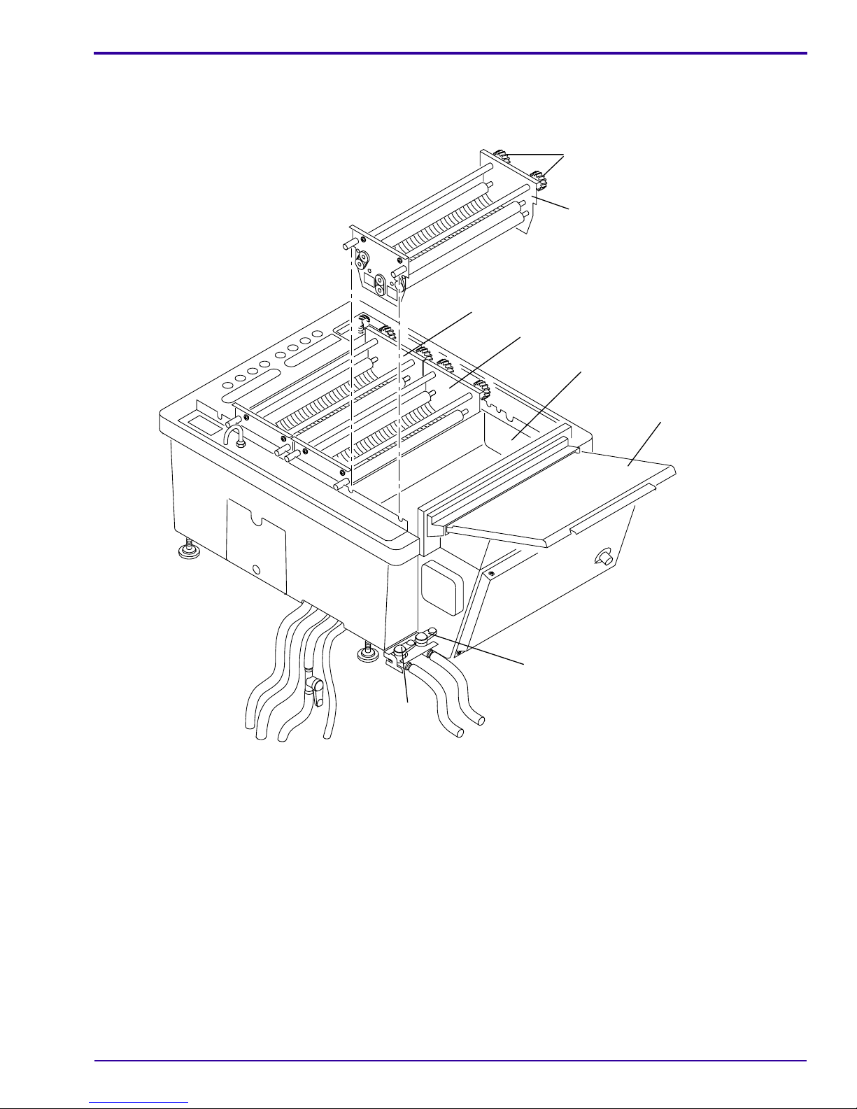
Operating Instructions
Draining and Cleaning the Tanks, in Preparation for Changing
the Chemicals or Storing the Processor for More Than a Week
Figure 5 Rinsing the Racks
19
12
16
15
39
2
23
H164_0014DCA
H164_0014DC
22
[1] Press the “ O ” on the “Power” Switch ( 20 ) to turn the Processor off.
[2] Turn off the main power circuit breaker at the wall of the darkroom or unplug the Processor.
[3] Turn off the water to the Processor.
[4] Check that the Drain Containers ( 36, 37, 38 ) will accommodate more solution and will not overflow.
[5] Drainthe developerand fixer solutions from the Tanks in the Processor by opening the red (developer) and blue
(fixer) Drain Valves ( 22, 23 ) .
[6] Remove the TopCover (1)by holding the front and back with both hands andlifting the Top Cover straight up.
[7] Remove the developer Evaporation Cover ( 11 ) , the Crossovers ( 14 ) , and the Racks ( 12, 15, 16 ) . Rinse
them with water.
[8] Close the Drain Valves ( 22, 23 ) .
[9] Remove the Replenishment Hoses ( 30, 31 ) from the Replenishment Containers ( 34, 35 ) . Empty and rinse
the Replenishment Containers with water.
[10] Fill the Replenishment Containers with water, and place the ends of the Replenishment Hoses in the
Containers.
9B8942 – November 1997 9
Page 10

OPERATORS MANUAL
[11] Place the Developerand Fixer Drain Hoses ( 24, 25 ) intothe Wash WaterDrain Container (36)or into the floor
drain (if allowed by local codes).
[12] Use the Pitcher ( 43 ) to pour 4 litres of water into the Developer and Fixer Tanks ( 39, 40 ) in the Processor.
[13] Turn on the power main circuit breaker at the wall or plug the Processor in.
[14] Press the “ | ” on the "Power" Switch ( 20 ) . This will circulate the water for a few minutes.
[15] Press [ DEV. ] ( 9 ) at least 3 times. Then, press [ FIX. ] ( 10 ) at least 3 times.
[16] Press the “ O ” on the "Power" Switch.
[17] Open the Drain Valves ( 22, 23 ) and drain the water from the Tanks in the Processor.
[18] Repeat Steps 12 - 17 two or three times to rinse the recirculation system of the Processor.
[19] When the rinse water in the Developer and Fixer Tanks is clean, press the “ O ” on the "Power" Switch.
[20] While the water isdraining, remove crystal depositsfrom the inner wallsof theDeveloperand Fixer Tanks ( 39,
40 ) with a non-abrasive sponge or lint-free cloth.
Note
Do not try to remove developer stains completely from the Racks and Tanks. This is normal.
[21] Check the 2 Screen Filters ( 42 ) .
(a) If the Filters are clogged, rub the Filters with a tooth brush.
(b) Rinse the Filters with water.
(c) Return the Filters to their original positions in the Tanks.
Figure 6 Cleaning the Tanks and the Screen Filters
42
41
40
H164_0022ACA
H164_0022AC
39
[22] Rinse the Tanks, and wipe them with a lint-free
cloth. To avoid any contamination, wipe the
DeveloperTank (39)first, thentheFixerTank(40
), and the Wash Tank ( 41 ) last.
[23] Installthe Racks ( 12, 15, 16 ) andCrossovers (14
) . Press on the corners of the Crossovers to
assure that they are fully seated.
[24] Install the Evaporation Cover ( 11 ) on the
Developer Rack ( 12 ) .
(a) First insert the end ofthe Evaporation Cover
that is next to the Drive Gears ( 19 ) .
(b) Insert the other end and press into place.
[25] Close the Top Cover ( 1 ) of the Processor.
[26] IftheProcessor will not be used formorethan one
week, leave the Tanks empty and the Top Cover
onandunplug the Processor. If youare replacing
the chemicals, see the next section.
10 November 1997 – 9B8942
Page 11
Replenishment Solutions
Section 3: Replenishment Solutions
Mixing the Developer and Fixer Replenishers
Use KODAKRP X-OMAT Developer Replenisher and KODAKRP X-OMATLO Fixer and Replenisher. Avoid
contaminating the chemical solutions by intermixing them. Clean the Pitcher (43)after each use. Carefully follow
the mixing directions packedwith the Replenishers. The 1000Processors areset before shipment tobe usedin the
Flooded Mode. Unless the mode of your Processor has been changed, you must add KODAKRP X-OMAT
Developer Starter to theDeveloper ReplenishmentContainer (35)at therate of3 fl oz/gallon or90 mL/3.8L. If you
are not sure whether the Processor is set to Flooded or Regular Mode, ask your service provider.
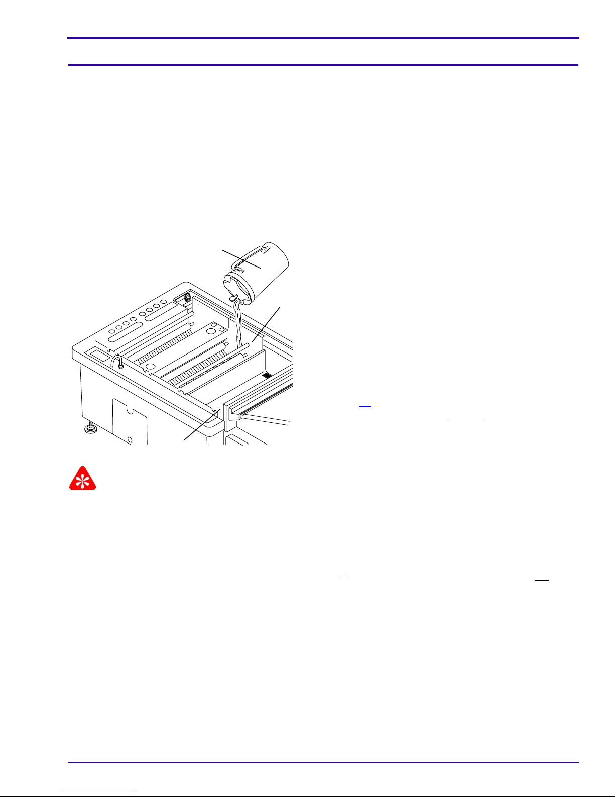
Filling the Tanks in the Processor
Figure 7 Filling the Tanks
H164_0024ACA
H164_0024AC
39
43
40
[1] Press the “O”onthe“Power”Switch (20)to turn
the Processor off.
[2] Turn off the main power circuitbreaker at the wall
of the darkroom or unplug the Processor.
[3] Turn off the water to the Processor.
[4] Checkthat the Developerand Fixer Drain Valves (
22, 23 ) are closed.
[5] Remove the Evaporation Cover ( 11 ) , the
Crossover(14)that has the “D” and “F” onit, and
the Developer Rack ( 12 ) .
[6] Rinse the Pitcher ( 43 ) .
[7] Pour 3.8 litres of the fixersolution mixed on Page
11 into the Pitcher ( 43 ) . Then, with the Fixer
Rack(15)inplace,carefully pour thesolutioninto
the Fixer Tank ( 40 ) .
Important
Avoid contamination of the developer by removing any splashes of fixer from the empty Developer Tank. Clean the
Pitcher after each use.
[8] Clean the Pitcher ( 43 ) under running water.
[9] Wipe the Developer Tank ( 39 ) with a damp towel.
[10] Install the Developer Rack ( 12 ) .
[11] Pour 3.8 litres of the developer solution mixed on Page 11 into the Pitcher. If Developer Starter has not been
added to the Developer Replenishment Container, add 3 fl oz (90 mL) of Starter to the Pitcher.
[12] Carefully pour the developer solution into the Developer Tank ( 39 ) .
[13] Install the:
• Evaporation Cover
• Crossover
• Top Cover on the Processor
[14] Insert the Drain Hoses ( 24, 25, 28 ) into the correct Drain Containers ( 38, 37, 36 ) .
• Do not insert the Hoses too far into the Containers.
• Do not bend the Hoses.
[15] Turn on the power main circuit breaker at the wall or plug in the Processor.
[16] Press the “ | ” on the “Power” Switch ( 20 ) to turn the Processor on.
9B8942 – November 1997 11
Page 12

OPERATORS MANUAL
[17] Turn on the water to the Processor.
12 November 1997 – 9B8942
Page 13

Preventive Maintenance
Section 4: Preventive Maintenance
Important
For trouble-free operation of the Processor, perform maintenance periodically in accordance with the following
suggestions.
Daily Maintenance
[1] At the start of each processing day, do the Start-Up procedure on Page 6.
[2] At the end of each processing day, do the Shutdown procedure on Page 8.
Weekly Maintenance
Caution
When you install or remove the Fixer Rack(15), be careful not to splashfixer chemicals into the Developer Tank (
39 ) . Do not try to clean developer stains completely from the Racks or Tanks.
[1] Remove the 2 Crossovers ( 14 ) , and the three Racks ( 12, 15, 16 ) , rinse them with water, and remove any
dirt with a damp towel.
(a) Remove any crystals from the Drive Gears ( 19 ) with a non-abrasive sponge or lint-free cloth.
(b) Rotate the Drive Gears by hand to check that each Roller ( 13 ) rotates smoothly.
(c) Check that the Rollers are not damaged.
(d) Checkthe WashRack(16)for biological growth. If necessary, rinsethe Rack well and clean itwith asoft
sponge or lint-free cloth.
[2] Wipe the underside of the Top Cover ( 1 ) with a damp towel.
[3] Check that developer has not splashed onto the Feed Tray. Wipe any splashes from the Feed Tray.
[4] Wipe the Feed Tray ( 21 ) with a dry lint-free cloth.
Monthly Maintenance
[1] In addition to the daily and weekly maintenance steps, do the following steps at least once a month.
[2] Unplug the Processor, and drain the Tanks.
[3] Use a soft, non-abrasive sponge or lint-free cloth to clean the three Racks ( 12, 15, 16 ) . Take care not to
damage the rubber Rollers.
[4] Check that all Rollers ( 13 ) rotate smoothly.
[5] Check each Tank for crystals from thesolutions. If crystals are found, softenthem witha damp towel andwipe
them off.
[6] Install new 2 Replenishment Filters ( 32 ) .
[7] If bacterial growth has occurred in the Wash Tank ( 41 ) of the Processor, do the following:
(a) Plug the end of the Wash Water Drain Hose ( 28 ) .
(b) Mix a mild solution of 90 mL (3 fl oz) of liquid bleach in 5.5 L (1.5 gal.) of water.
(c) Fill the Wash Tank ( 41 ) until the bleach solution comes out of the Wash Water Overflow Hose ( 29 ) .
(d) Let the bleach solution stay in the Wash Tank for 15 - 20 minutes.
(e) Unplug the Wash Water Drain Hose.
(f) When the bleach solution has emptied from the Wash Tank, rinse the Wash Tank 3 times with water.
9B8942 – November 1997 13
Page 14

OPERATORS MANUAL
[8] Mix new chemicals. See Page 11.
Note
If the image quality of the film has been satisfactory, you may use the solutions longer than a month.
[9] Install the Racks ( 12, 15, 16 ) .
[10] Install the Crossovers ( 14 ) .
(a) Match the red “D” and blue “F” and white “W” on the Crossovers with the same letters on the Racks.
(b) Push the right and left corners of the Crossover to check that it is set accurately.
[11] Rotate the Drive Gears ( 19 ) on the Racks to engage them with the Drive Shaft ( 18 ) .
[12] Fill the Developer and Fixer Tanks ( 39, 40 ) with solutions. See Page 11.
Troubleshooting
Ifyou have a problem with the Processor,checkthis list of possible causes. Iftheproblem is not solved by theactions
listed here, contact your service provider.
Action If this does not solve the
Problem Problem Analysis
Film is slanted • Film is inserted improperly.
• Springs that squeeze the Rollers together
are dislocated.
Film is jamming • Film does not enter between the Rollers.
• Crossovers are not installed in the
Processor.
• An air tube in the Dryer Rack is dislodged.
• The Top Cover is misaligned.
Scratches or marks on the film surface:
1. Linear scratches
or dirt along the film
transport direction
2. Marks at 63 mm
intervalsalongthefilm
transport direction
3. Random scratch or
mark
• The Rollers are scratched or dirty • For black marks, check and gently
• The Rollers are flawed or dirty. • For black marks, check and gently
• The Feed Tray is dirty • Clean the Feed Tray.
problem, contact your service provider.
• Insert film along the left side of the
Feed Tray.
• Attach the springs correctly.
• Check whether the Springs that
squeeze the Rollers are dislocated.
Reattach.
• Install the Crossovers.
• Call the service provider.
• Install the Top Cover correctly.
clean the parts in theRollers alongthe
film path.
• For white marks, check and gently
clean the Rollers in the Developer
Rack, using KODAK Roller Transport
Cleanup Film CAT No. 166 2303.
clean the Rollers in the Developer
Rack.
• For white marks, check and gently
cleanthe Rollers in the Fixer andDryer
Racks.
14 November 1997 – 9B8942
Page 15

Problem Problem Analysis
Fogging • The developer is contaminated.
• The Top Cover is not on properly.
• The room is too bright.
• Felt or foam is coming off the Processor.
Film cannot be
inserted
• The film is held by moisture on the Feed
Tray.
• Top Cover is misaligned.
Base density too high • The fixer has mixed with the developer.
• The developer has deteriorated.
Base density too low,
improper development
• Replenishment amount is insufficient.
• The chemicals are deteriorated.
• The developer temperature is too low.
Improper fixing, poor
transparency
Improper washing,
• Replenishment amount is insufficient.
• The fixer is deteriorated.
• Wash Tank is not full. • Adjustthe flow ofwatercoming into the
white deposits on the
film surface
Improper drying • The preset temperature is incorrect.
• An air tube in the Dryer Rack is dislodged.
Solution in a Tank is
not moving
Air could be trapped in the Recirculation
Pump.
Preventive Maintenance
Action If this does not solve the
problem, contact your service provider.
• Drain the developer from the
Processor, and do the cleaning
procedureon Page 9 fortheDeveloper
Tank.
• Check that the Top Cover is fully
closed.
• Reduce the light in the room.
• Call the service provider.
• Clean and dry the Feed Tray. See
Page 7, for correct film-feeding
instructions.
• Install the Top Cover correctly.
• Drain the developer from the
Processor, and do the cleaning
procedureon Page 9 fortheDeveloper
Tank.
• Mix new developer.
• Check the volume of replenishment
solutions in the Replenishment
Containers. Check that the Hoses are
not bent.
• Replace the chemicals.
• Contact the service provider.
• Check the preset replenishment
amount.
• Replace the chemicals.
Processor.
• Adjust the Dryer Temperature Control
Knob.
• Call the service provider.
Open the Drain Valve and drain a small
amount of solution. If the solution does not
start to move, do it again. If after several
attempts, there is still no movement, call
the service provider.
9B8942 – November 1997 15
Page 16

Section 5: Warranty (U.S. only)
Note
Kodak warrants this KODAK X-OMAT 1000 or 1000A or 1000J Processor to function properly for one
year from the date of initial installation, when installed within 1 year from the date of shipment.
Warranty Repair Coverage
If this equipment does not function properly duringthe warranty period, thedealer for KODAK X-OMAT
Processors who sold the equipment will provide or arrange for repair of the equipment during the
dealer's normal working hours. Such repair service will include any necessary adjustments and/or
replacement of parts necessary to maintain your equipment in good working order.
How to Obtain Service
Should equipment require service, refer to the sales contract for detailson whom to call for service, or
contact the dealer for KODAK X-OMAT Processors who sold the equipment.
Limitations
Warranty service is limited to the contiguous United States, the island of Oahu in Hawaii, and
certain areas of Alaska.
This warranty does not cover: circumstances beyond Kodak's control; misuse; abuse; any
attachments, accessories, or alterations not marketed by Kodak (including service or parts to
correct problems resulting from the use ofsuch attachments,accessories or alterations); failure to
follow Kodak's operating instructions; or supply items.
Kodak makes no other warranties, express, implied, or of merchantability for this equipment.
Repair without charge is Kodak's and the dealer's only obligation under this warranty.
• Kodak will not be responsible for any consequential or incidental damages resulting from the
sale, use, or improper functioning of this equipment even if loss or damage is caused by the
negligence or other fault of Kodak.
• Such damages for which Kodak will not be responsible, include, but are not limited to, loss of
revenue or profit, downtime costs, loss of use of the equipment, cost of any substitute
equipment, facilities or services or claims of your customers for such damages.
This limitation of liabilitywill notapply to claims forinjury topersons ordamage to property caused
by the sole negligence or fault of Kodak or by persons under its direction or control.
Warranty (U.S. only)
Table 1 Publication History
Print Date Pub. No. ECO No.
July 1997 9B8942 2504-470 All Pages om3482_1_470.doc First printing.
Nov 1997 9B8942 2504-475 All Pages om3482_1_475.doc Minor updates and
Printed in U.S.A. • om3482_1.fm
EASTMAN KODAK COMPANY
Rochester, NY 14650
Kodak
Affected
Pages File Name Notes
translated into 6
languages.
and
X-Omat
are trademarks.
HEALTH IMAGING
 Loading...