

Page 1

KODAK 9000 3D Extraoral Imaging System
User Guide
Page 2

Notice
Congratulations on your purchase of the KODAK 9000 Extraoral Imaging System. Thank you for your confidence in
our products and we will do all in our power to ensure your complete satisfaction.
The User Guide for the KODAK 9000 3D Extraoral Imaging System includes information both on the Panoramic
features as well as the 3D features. If you have purchase only the KODAK 9000 Panoramic system, information
relevant to 3D does not apply to your radiological system. We recommend that you thoroughly familiarize yourself
with this Guide in order to make the most effective use of your system.
The information contained in this Guide may be subject to modification without notice, justification or notification to
the persons concerned.
No part of this Guide may be reproduced without the express permission of Carestream Health, Inc.
This document is originally written in English.
Manual Name: KODAK 9000 3D Extraoral Imaging System User Guide
Part Number: SM710
Revision Number: Edition 01
Print Date: 11/2007
The brand names and logos reproduced in this Guide are copyright.
KODAK is a trademark of KODAK used under License.
KODAK 9000 3D Extraoral Imaging System, complies with Directive 93/42/CEE relating to medical equipment.
Page 3

KODAK 9000 3D Extraoral Imaging System_User Guide (SM710)_Ed 01 iii
Contents
1—About This Guide
Conventions in this Guide. . . . . . . . . . . . . . . . . . . . . . . . . . . . . . . . . . . . . . . . . . . . . . . . . . . . . . . . . . . . . . . . . . . . . . .1–1
Note to the User. . . . . . . . . . . . . . . . . . . . . . . . . . . . . . . . . . . . . . . . . . . . . . . . . . . . . . . . . . . . . . . . . . . . . . . . . . . . . . .1–2
Warning and Safety Instructions . . . . . . . . . . . . . . . . . . . . . . . . . . . . . . . . . . . . . . . . . . . . . . . . . . . . . . . . . . . . . . . . . .1–2
Marking and Labeling Symbols . . . . . . . . . . . . . . . . . . . . . . . . . . . . . . . . . . . . . . . . . . . . . . . . . . . . . . . . . . . . . . . . . .1–4
2—KODAK 9000 3D DIGITAL IMAGING UNIT OVERVIEW
Functional Overview. . . . . . . . . . . . . . . . . . . . . . . . . . . . . . . . . . . . . . . . . . . . . . . . . . . . . . . . . . . . . . . . . . . . . . . . . . .2–1
Control Panel Overview . . . . . . . . . . . . . . . . . . . . . . . . . . . . . . . . . . . . . . . . . . . . . . . . . . . . . . . . . . . . . . . . . . . . . . . .2 –4
X-Ray Remote Control Overview. . . . . . . . . . . . . . . . . . . . . . . . . . . . . . . . . . . . . . . . . . . . . . . . . . . . . . . . . . . . . . . . .2–5
Positioning Accessories and Replacement Parts. . . . . . . . . . . . . . . . . . . . . . . . . . . . . . . . . . . . . . . . . . . . . . . . . . . . . .2–6
3—IMAGING SOFTWARE OVERVIEW
PC System Requirements . . . . . . . . . . . . . . . . . . . . . . . . . . . . . . . . . . . . . . . . . . . . . . . . . . . . . . . . . . . . . . . . . . . . . . .3–1
General Software Overview . . . . . . . . . . . . . . . . . . . . . . . . . . . . . . . . . . . . . . . . . . . . . . . . . . . . . . . . . . . . . . . . . . . . .3–2
Kodak Dental Imaging Software . . . . . . . . . . . . . . . . . . . . . . . . . . . . . . . . . . . . . . . . . . . . . . . . . . . . . . . . . . . . . .3–2
Acquisition Interface Module. . . . . . . . . . . . . . . . . . . . . . . . . . . . . . . . . . . . . . . . . . . . . . . . . . . . . . . . . . . . . . . . .3–2
Kodak Dental Imaging Software Overview . . . . . . . . . . . . . . . . . . . . . . . . . . . . . . . . . . . . . . . . . . . . . . . . . . . . . . . . .3–3
Patient Window Overview . . . . . . . . . . . . . . . . . . . . . . . . . . . . . . . . . . . . . . . . . . . . . . . . . . . . . . . . . . . . . . . . . . .3–3
Imaging Window Overview . . . . . . . . . . . . . . . . . . . . . . . . . . . . . . . . . . . . . . . . . . . . . . . . . . . . . . . . . . . . . . . . . .3–5
3D Imaging Windows Overview . . . . . . . . . . . . . . . . . . . . . . . . . . . . . . . . . . . . . . . . . . . . . . . . . . . . . . . . . . . . . .3–8
Acquisition Interface Module . . . . . . . . . . . . . . . . . . . . . . . . . . . . . . . . . . . . . . . . . . . . . . . . . . . . . . . . . . . . . . . . . . .3–14
Panoramic Acquisition Window Overview . . . . . . . . . . . . . . . . . . . . . . . . . . . . . . . . . . . . . . . . . . . . . . . . . . . . .3–14
Panoramic Program Pane. . . . . . . . . . . . . . . . . . . . . . . . . . . . . . . . . . . . . . . . . . . . . . . . . . . . . . . . . . . . . . . .3–16
Panoramic Patient Pane . . . . . . . . . . . . . . . . . . . . . . . . . . . . . . . . . . . . . . . . . . . . . . . . . . . . . . . . . . . . . . . . .3–17
Panoramic Parameter Pane. . . . . . . . . . . . . . . . . . . . . . . . . . . . . . . . . . . . . . . . . . . . . . . . . . . . . . . . . . . . . . .3–18
3D Acquisition Window Overview . . . . . . . . . . . . . . . . . . . . . . . . . . . . . . . . . . . . . . . . . . . . . . . . . . . . . . . . . . .3–19
3D Program Pane . . . . . . . . . . . . . . . . . . . . . . . . . . . . . . . . . . . . . . . . . . . . . . . . . . . . . . . . . . . . . . . . . . . . . .3–21
3D Patient Pane . . . . . . . . . . . . . . . . . . . . . . . . . . . . . . . . . . . . . . . . . . . . . . . . . . . . . . . . . . . . . . . . . . . . . . .3–22
3D Parameter Pane. . . . . . . . . . . . . . . . . . . . . . . . . . . . . . . . . . . . . . . . . . . . . . . . . . . . . . . . . . . . . . . . . . . . .3–23
4—GETTING STARTED
Starting the Imaging Software. . . . . . . . . . . . . . . . . . . . . . . . . . . . . . . . . . . . . . . . . . . . . . . . . . . . . . . . . . . . . . . . . . . .4–1
Creating a Patient Record . . . . . . . . . . . . . . . . . . . . . . . . . . . . . . . . . . . . . . . . . . . . . . . . . . . . . . . . . . . . . . . . . . . . . . .4–1
Accessing the Acquisition Windows. . . . . . . . . . . . . . . . . . . . . . . . . . . . . . . . . . . . . . . . . . . . . . . . . . . . . . . . . . . . . . .4–2
Switching On the Unit. . . . . . . . . . . . . . . . . . . . . . . . . . . . . . . . . . . . . . . . . . . . . . . . . . . . . . . . . . . . . . . . . . . . . . . . . .4–2
5—ACQUIRING IMAGES
Acquiring a Panoramic, TMJ x2 or Sinus Image . . . . . . . . . . . . . . . . . . . . . . . . . . . . . . . . . . . . . . . . . . . . . . . . . . . . .5–1
Preparing the Unit and Setting the Acquisition Parameters. . . . . . . . . . . . . . . . . . . . . . . . . . . . . . . . . . . . . . . . . .5–1
Preparing and Positioning the Patient. . . . . . . . . . . . . . . . . . . . . . . . . . . . . . . . . . . . . . . . . . . . . . . . . . . . . . . . . . . 5–2
Launching the X-ray. . . . . . . . . . . . . . . . . . . . . . . . . . . . . . . . . . . . . . . . . . . . . . . . . . . . . . . . . . . . . . . . . . . . . . . .5–4
Page 4

iv
Contents
Acquiring a TMJ x4 Image . . . . . . . . . . . . . . . . . . . . . . . . . . . . . . . . . . . . . . . . . . . . . . . . . . . . . . . . . . . . . . . . . . . . . .5–6
Acquiring a 3D Image . . . . . . . . . . . . . . . . . . . . . . . . . . . . . . . . . . . . . . . . . . . . . . . . . . . . . . . . . . . . . . . . . . . . . . . . . .5–7
Preparing the Unit and Setting the Acquisition Parameters . . . . . . . . . . . . . . . . . . . . . . . . . . . . . . . . . . . . . . . . . .5–7
Preparing and Positioning the Patient. . . . . . . . . . . . . . . . . . . . . . . . . . . . . . . . . . . . . . . . . . . . . . . . . . . . . . . . . . .5–7
Launching the x-ray . . . . . . . . . . . . . . . . . . . . . . . . . . . . . . . . . . . . . . . . . . . . . . . . . . . . . . . . . . . . . . . . . . . . . . .5–10
Manually Pre-Setting the Patient Positioning. . . . . . . . . . . . . . . . . . . . . . . . . . . . . . . . . . . . . . . . . . . . . . . . . . . .5–11
6—MAINTENANCE
Daily . . . . . . . . . . . . . . . . . . . . . . . . . . . . . . . . . . . . . . . . . . . . . . . . . . . . . . . . . . . . . . . . . . . . . . . . . . . . . . . . . . . . . . .6–1
Monthly . . . . . . . . . . . . . . . . . . . . . . . . . . . . . . . . . . . . . . . . . . . . . . . . . . . . . . . . . . . . . . . . . . . . . . . . . . . . . . . . . . . . .6–1
Annually . . . . . . . . . . . . . . . . . . . . . . . . . . . . . . . . . . . . . . . . . . . . . . . . . . . . . . . . . . . . . . . . . . . . . . . . . . . . . . . . . . . .6–2
7—TECHNICAL SPECIFICATIONS
Compliance with International Standards . . . . . . . . . . . . . . . . . . . . . . . . . . . . . . . . . . . . . . . . . . . . . . . . . . . . . . . . . . .7–1
Manufacturer . . . . . . . . . . . . . . . . . . . . . . . . . . . . . . . . . . . . . . . . . . . . . . . . . . . . . . . . . . . . . . . . . . . . . . . . . .7–1
Model . . . . . . . . . . . . . . . . . . . . . . . . . . . . . . . . . . . . . . . . . . . . . . . . . . . . . . . . . . . . . . . . . . . . . . . . . . . . . . . .7–1
Compliance with International Regulations. . . . . . . . . . . . . . . . . . . . . . . . . . . . . . . . . . . . . . . . . . . . . . . . . . .7–1
Compliance with International Standards. . . . . . . . . . . . . . . . . . . . . . . . . . . . . . . . . . . . . . . . . . . . . . . . . . . . .7–1
Ambient Operating Conditions. . . . . . . . . . . . . . . . . . . . . . . . . . . . . . . . . . . . . . . . . . . . . . . . . . . . . . . . . . . . .7–1
Storage Conditions . . . . . . . . . . . . . . . . . . . . . . . . . . . . . . . . . . . . . . . . . . . . . . . . . . . . . . . . . . . . . . . . . . . . . .7–1
Transport Conditions . . . . . . . . . . . . . . . . . . . . . . . . . . . . . . . . . . . . . . . . . . . . . . . . . . . . . . . . . . . . . . . . . . . .7–1
Unit Technical Specifications . . . . . . . . . . . . . . . . . . . . . . . . . . . . . . . . . . . . . . . . . . . . . . . . . . . . . . . . . . . . . . . . . . . .7–2
Unit Electronic Specifications . . . . . . . . . . . . . . . . . . . . . . . . . . . . . . . . . . . . . . . . . . . . . . . . . . . . . . . . . . . . . . . . . . .7–4
X-Ray Generator Technical Specifications . . . . . . . . . . . . . . . . . . . . . . . . . . . . . . . . . . . . . . . . . . . . . . . . . . . . . . . . .7–5
Page 5

KODAK 9000 3D Extraoral Imaging System_User Guide (SM710)_Ed 01 1–1
Chapter 1
About This Guide
Conventions in this Guide
The following special messages emphasize information or indicate potential risk to personnel
or equipment:
WARNING
Warns you to avoid injury to yourself or others by following the
safety instructions precisely.
CAUTION
Alerts you to a condition that might cause serious damage.
IMPORTANT
Alerts you to a condition that might cause problems.
NOTE
Emphasizes important information.
TIP
Provides extra information and hints.
Page 6

Note to the User
1–2 About This Guide
Note to the User
WARNING
X-rays can be harmful and dangerous if not used properly. The
instructions and warnings contained in this guide must be therefore
carefully followed.
As a manufacturer of radiology units that conform to stringent radiological protection
standards in force throughout the world, we guarantee a maximum degree of protection against
radiation hazards. Nonetheless, you are handling a radiology unit specially designed to emit
x-ray doses in order to carry out a medical diagnosis.
The room in which your radiology Unit is to be installed must comply with all official
regulations applicable to protection against radiatio n. You must install your radiology unit in a
room protected against x-ray emission. This room must reduce to at least 12db the frequency
interferences of the 30MHz to 1GHz band.
Your local representative will assist you in the initial use of your radiology Unit and will
supply any relevant information you may require.
T o use and operate your pano ramic unit and your digital imaging software you must follow the
instructions contained in this guide.
Warning and Safety Instructions
When operating the Kodak 9000 3D unit, observe the following warning and safety
instructions:
DANGER OF ELECTRIC SHOCK
This is an electrical Unit. DO NOT expose it to water spray. Such action
may cause an electric shock or a malfunction of the Unit.
LASER WARNING
For maximum safety, advise the patient not to look at the beam.
Before turning on the beams, lower the Frankfurt plane beam to
the lowest level. While making adjustments, ensure that the beam is
not directed into the patient's eyes.
LASER RADIATION
DO NOT STARE INTO BEAM
CLASS 2 LASER PRODUCT
Maximum laser output:1mW,650nm
IEC60825-1:1993+A1:1997+A2:2001
Page 7

Warning and Safety Instructions
KODAK 9000 3D Extraoral Imaging System_User Guide (SM710)_Ed 01 1–3
WARNINGS:
• You are responsible for the operation and maintenance of this unit. Only legally
qualified persons can operate this unit. DO NOT open the cover of the unit.When
necessary, have a trained authorized service technician carry out inspection and
maintenance operations.
• Install this Unit in an x-ray room that complies with current installation
standards. From this location, you must be able to maintain visual or audio
communication with the patient and be able to access the Acquisition interface
module during exposure. This Unit must be permanently connected to the
ground with a fixed power supply cable.
• DO NOT place the PC and the peripheral equipment connected to it in the
immediate vicinity of the patient in the Unit. Leave at least 1.5 m distance
between the patient and the Unit. The PC and the peripheral equipment must
conform to the IEC60950 standard.
• See your computer installation guide for details of the data processing system,
PC and screen. Leave a sufficient amount of clear space around the CPU to
ensure that it is properly ventilated.
• To obtain maximum image quality and visual comfort, position the screen to
avoid direct light reflections from internal or external lighting.
• DO NOT operate the Unit if there is the threat of an earthquake. Following an
earthquake, ensure that the Unit is operating satisfactorily before using it again.
Failure to observe this precaution may expose patients to hazards.
• X-ray equipment is hazardous to patients and the operator if you do not observe
the exposure safety factors and operating instructions.
• DO NOT place objects within the field of operation of the Unit.
• The patient should wear a protective lead-lined shoulder apron, unless other
Radiation Protection Protocols apply locally.
• Disinfect any parts of the Unit that come into contact with the patient and the
operator after each patient has been exposed to x-rays.
• While adjusting the height of the Unit, ensure that the patient is kept clear of the
mechanism.
• When the Unit is not in use, ensure that the ON/OFF switch is set to OFF (O).
• If the Unit develops a fault, switch it to off (O), display an “Unserviceable” notice
and contact a service technician.
• To dispose of the Unit or its components, contact a service technician.
• Ask the patient to refrain from moving during the entire period of exposure.
• Ask the patient to remain still until the Unit arm has stopped moving and the
RESET movement has completed.
• DO NOT use this Unit in conjunction with oxygen-rich environments. This Unit
is not intended for use with flammable anesthetics or flammable agents.
Page 8

Marking and Labeling Symbols
1–4 About This Guide
Marking and Labeling Symbols
Type B device symbol complying with the IEC 60601-1
standard
In the EEC, this symbol indicates: DO NOT discard this
product in a trash receptacle; use an appropriate recovery
and recycling facility .
Contact your local sales representative for additional
information on the collection and recovery programs
available for this product
WARNING and IONIZING RADIATION symbols warn
you about radiation dangers.
LASER WARNING
Laser radiation. DO NOT stare into the beam.
Class 2 laser product.
Maximum output power: 1mW, 650 nm (IEC 60825-1
standard)
This Unit emits laser radiation.
LASER RADIATION
DO NOT STARE INTO BEAM
CLASS 2 LASER PRODUCT
Maximum laser output:1mW,650nm
IEC60825-1:1993+A1:1997+A2:2001
Page 9

KODAK 9000 3D Extraoral Imaging System_User Guide (SM710)_Ed 01 2–1
Chapter 2
KODAK 9000 3D DIGITAL IMAGING UNIT
OVERVIEW
The KODAK 9000 3D digital imaging unit is compliant with the requirements of the EEC and
international medical standards.
The KODAK 9000 3D Unit has been designed to carry out the following radiological
examinations:
• Panoramic
• Maxillary Sinus
• Temporomandibular Joints (TMJ)
• 3D images
The KODAK 9000 3D Unit is composed of the following functional components:
• Control Panel
• Remote Control
Functional Overview
The following figures illustrate the components of the KODAK 9000 3D Unit.
Figure 2-1 illustrates the up and down movement of the Unit mobile component and the 180°
rotation of the rotative arm.
Figure 2–1 KODAK 9000 3D Unit mobile components
Page 10

Functional Overview
2–2 KODAK 9000 3D D IGITAL IMAGING UNIT OVERVIEW
Figure 2–2 KODAK 9000 3D Unit functional components
1 ON/OFF button 6 Temple supports
2 Unit fixed arm 7 Sensor
3 Control panel 8 Generator
4 Hand Grips 9 Unit rotative arm
5 Chin rest ba se 10 X-Ray remote control
5 a Panoramic chin rest 11 PC hosting the imaging and the acquisition software
5 b 3D chin rest and bite block
10
11
6
8
5a
2
1
7
9
3
4
5
5b
5
Page 11

Functional Overview
KODAK 9000 3D Extraoral Imaging System_User Guide (SM710)_Ed 01 2–3
Figure 2–3 KODAK 9000 3D Unit Positioning Laser Beam components
1 3D central positioning laser beam
2 Mid-sagittal positioning laser beam
3 Horizontal positioning laser beam
4 3D Field of View (FoV) positioning
laser beam
21
2
1
4
3
A
A
B
B
1
2
4
3
Page 12

Control Panel Overview
2–4 KODAK 9000 3D D IGITAL IMAGING UNIT OVERVIEW
Control Panel Overview
The control panel is an alphanumeric, digital soft touch console. It allows the operator to
control certain Unit functions. It also displays the operating parameters and error messages.
Figure 2–4 Unit Control Panel
1 Height Adjustment button: Adjusts the height of the unit to the height of the
patient.
2 3D Head Adjustment button: Adjusts the patient head to the x-ray beams.
3 3D Adjustment button: Adjusts the Unit arm movements to correctly position
the patient for 3D acquisition.
4 Laser Beam button: Activates the beams to correctly position the patient.
5 3D Position Verification button: Verifies the correct 3D positioning.
6 Reset button: Resets the Unit arm to the initial position to enable the patient to
enter and exit the Unit.
7 3D Memorization button: Memorizes the 3D current positioning parameter
settings that override the default parameters.
8 Display Screen: Displays the current acquisition parameters and the error
messages.
9 Ready Indicator LED: Green indicates the Unit is ready for acquisit ion .
10 X-Ray Emission LED: Yellow indicates x-rays are being emitted.
11 System Status LED: Red indicates error alerts.
mem
kV
mA S
76
1
23
5410911
8
Page 13

X-Ray Remote Control Overview
KODAK 9000 3D Extraoral Imaging System_User Guide (SM710)_Ed 01 2–5
X-Ray Remote Control Overview
The x- ray remote control enables you to launch a radiological image acquisition via the
exposure button from outside the x-ray room. You must press and hold the exposure button
until the end of acquisition. Premature release of the exposure button interrupts the
acquisition.
Figure 2–5 X-Ray Remote Control
1 Exposure button: launches image acquisition.
1
Page 14

Positioning Accessories and Replacement Parts
2–6 KODAK 9000 3D D IGITAL IMAGING UNIT OVERVIEW
Positioning Accessories and Replacement Parts
The following accessories are used when positioning a patient. They are delivered with the
KODAK 9000 3D digital imaging unit.
Table 2–1 Panoramic Positioning Accessories and Replacement Parts
Accessory Description
• Panoramic chin rest
• TMJ x2
• Sinus
TMJ x4 nose rest
Panoramic standard bite block
Bite block for edentulous patients
Single use sheaths for bite blocks
(500 pcs box)
Table 2–2 3D Positioning Accessories and Replacement Parts
Accessory Description
3D bite block
3D chin rest
Page 15

KODAK 9000 3D Extraoral Imaging System_User Guide (SM710)_Ed 01 3–1
Chapter 3
IMAGING SOFTWARE OVERVIEW
PC System Requirements
This section specifies the minimum PC system requirements for Kodak 9000 3D extraoral
imaging system software.
IMPORTANT
It is MANDATORY to check that the PC system configuration is
compatible with the PC system requirements for the Kodak 9000 3D
software. If necessary you MUST update your PC system configuration.
Kodak 9000 3D MUST be connected to the PC via a point-to-point Ethernet
link and not via a LAN. DO NOT place the PC and the peripheral
equipment connected to it in the immediate vicinity of the patient in the
Unit. Leave at least 1.5 m distance from the Unit. The PC and the
peripheral equipment must conform to the IEC 60950 standard.
Table 3–1 Minimum PC System Requirements
Item
Minimum Workstation Image
Viewing Requirements
Minimum Workstation
Acquisition Requirements
Comments
CPU 2 GHz Intel Duo Core 3 GHz Intel Pentium 4
RAM 2 GB 2GB RAM has a major impact on
system performance.
Hard disk drive
• 1.2 GB for software installation
• 80 GB free space to use the
software
1.2 GB for software installation
Graphic board Nvidia / ATI based board supporting
Open Glide 1.2 with 256 MB of video
RAM on AGP x8 video bus (example:
Nvidia GeForce 6800 GT)
Nvidia board on PCI Express video
bus, minimum GeForce 8800 GTS
640 MB of video RAM, or Quadro
FX 4600 768 MB of video RAM
The video RAM has major impact
on system performance.
Monitor
• 1 monitor
• 17" or larger
• 1024 x 768 minimum screen
resolution - 32 bits color mode
• 1 monitor
• 17"
• 1024 x 768 minimum screen
resolution
Your monitor is a vital component
in displaying quality images.
Low-quality screens will prevent
you from proper diagnoses and
treatment.
Operating system
• Windows 2000 SP4
• Windows XP Home / Pro
edition SP2
• Windows Vista 32 bits
• Windows 2000 SP4*
•
Windows XP Home / Pro
edition SP2
• Windows Vista 32 bits*
Ethernet interface 1 Ethernet interface 2 Ethernet interfaces (100Mbits)
CD/DVD drive A CD-ROM drive is required to install
the product.
A CD-ROM drive is required to
install the product.
Page 16

General Software Overview
3–2 IMAGING SOFTWARE OVERVIEW
General Software Overview
The Kodak 9000 3D extraoral imaging system operates with the following software:
• Kodak dental imaging software
• Acquisition interface module
Kodak Dental Imaging Software
The Kodak dental imaging software is a user-friendly working interface that was designed and
developed specifically for radiological diagnosis. It is the common imaging platform for all
our digital systems for dentistry.
The Kodak dental imaging software has the following features:
• Patient record management via Patient Window features
• Extraoral and intraoral image management via Imaging Window features
• 3D image management via 3D Imaging Window features
Acquisition Interface Module
The Acquisition interface module is a user-friendly working interface that was designed and
developed specifically for Kodak 9000 3D extraoral imaging system.
The Acquisition interface module has the following features:
• Panoramic acquisition interface via Panoramic Acquisition Window
• 3D acquisition interface via 3D Acquisition Window
Backup Media Removable/portable, external hard
disk drive
Removable/portable, external hard
disk drive.
We strongly recommend a daily
backup of x-ray images and
patient records.
* NOTE: The indicated operating systems considerably increase the 3D volume image reconstruction time. The normal
duration of a few minutes is increased by more than an hour.
Table 3–1 Minimum PC System Requirements
Item
Minimum Workstation Image
Viewing Requirements
Minimum Workstation
Acquisition Requirements
Comments
NOTE
If you access the Imaging Window directly from your own patient
management software, you will not see the Patient Window.
Page 17

Kodak Dental Imaging Software Overview
KODAK 9000 3D Extraoral Imaging System_User Guide (SM710)_Ed 01 3–3
Kodak Dental Imaging Software Overview
Patient Window Overview
The Patient Window is the first window that appears when you launch the Kodak dental
imaging software. This window is the main patient record management interface that provides
you with all the patient record functions.
Figure 3–1 Patient Window
1Title Bar: Displays:
• Software name
• Software version
• Practitioner name
2
Menu Bar: Provides access to the following functions:
3 Toolbar: Provides quick access
to the following menu functions:
Menu Submenu Description
Patient New Creates a new patient record
Find Finds a patient file
Modify Modifies a patient record
Delete Deletes a patient file
Imaging Leads to the Imaging window
1
2
3
5
4
Page 18

Kodak Dental Imaging Software Overview
3–4 IMAGING SOFTWARE OVERVIEW
Exit Exits the Patient window
Picture Insert picture Inserts the patient picture
Remove picture Removes the patient picture
Utilities Reindex Regenerates all the index table
Archival... Archives images before the given
date
Options Preferences... Configures the language and the
database location
Toolbar Hides or shows the toolbar
?
Help topics Displays the online contextual
help
About... Lists the following information:
• Software version
• Copyright
4 Patient photograph if available.
5 Patient Record Pane: Patient information that you must enter in each field.
NOTE
For information and procedures on how to use these functions, from
the menu bar click ? to access the online help.
Page 19

Kodak Dental Imaging Software Overview
KODAK 9000 3D Extraoral Imaging System_User Guide (SM710)_Ed 01 3–5
Imaging Window Overview
The Imaging Window is the main imaging interface that provides you with the panoramic
imaging functions.
Figure 3–2 Imaging Window
1Title Bar: Displays:
• Software name
• Software version
• Practitioner name
• Patient name
2
Menu Bar: Provides access to the following functions:
3 Toolbar: Provides quick
access to the following
menu functions:
Menu Submenu Description
File New panoramic
image
Accesses the Panoramic
Acquisition Window for a
panoramic image
New 3D image Accesses the 3D Acquisition
Window for a 3D image
History Open Opens the patient history record with
image files
Save Saves the acquired image
Close Closes the patient image
Page 20
Kodak Dental Imaging Software Overview
3–6 IMAGING SOFTWARE OVERVIEW
Delete Deletes selected image
Print Prints the patient image
Print Setup Sets up the printing parameters
Slide Show Displays a set of images in a
particular sequence
Report Creates customized letters
Word Report Creates a report template
Import image file Imports images from a selected
folder
Import digital camera Imports images acquired with a
digital camera
DICOMDIR Imports/Exports DICOM images
TWAIN Scans images
Copy Copies selected image to clipboard
Paste Pastes selected image
Send to Sends the selected image either via
e-mail or to a selected folder
Exit Exits the Imaging Window
Context Save context Saves the current images and screen
display
Open context Opens the saved images and screen
display
Print context Prints the selected image s
TUV Panoramic
certification
Creates one series of quality
reference images at installation (by
installer)
Panoramic constancy
test
Generates monthly images to
compare with reference images
Options Preferences Customizes specifi c prefe rences,
such as, interface and online help
languages, practitioner name, image
preferences and so on.
Advanced options Enters acquisition location data
information
Customized Customizes contextual toolbars
Page 21

Kodak Dental Imaging Software Overview
KODAK 9000 3D Extraoral Imaging System_User Guide (SM710)_Ed 01 3–7
Window Clear screen Clears the screen
Rearrange screen Rearranges by default the displayed
content of the screen
Iconize all Reduces images to icons
Tools default position Positions the imaging to olbar, control
panel and dental arch in the default
position
Main toolbar Displays the main toolbar if checked
?
Help topics...
F1
Displays the online contextual help
Tooltips Displays, if checked, the name of the
icon when the cursor points at it
Install masking files Installs the masking files in case the
files were not installed initially
License... Displays License information
About... Displays Kodak dental imaging
software version information
4 Dental Arch Pane: Displays the existing teeth images of the patient dental arch. To open different
history types to access patient images:
• Click P for a display of all Panoramic images.
• Click F for a reduced history with the FMS displayed.
• Click C for a reduced history with the Cephalometric images displayed.
• Click to access the Patient History dialog box.
5 Control Panel: Adjusts and enhances certain zones of the image for a clearer display.
6 Image Windows: Depending on the image type, the title bar displays different information.
7 Contextual Toolbar: The toolbar type depends on the image type context. You can reposition the
toolbar.
NOTE
For information and procedures on how to use these functions, from
the menu bar click ? to access the online help.
Page 22
Kodak Dental Imaging Software Overview
3–8 IMAGING SOFTWARE OVERVIEW
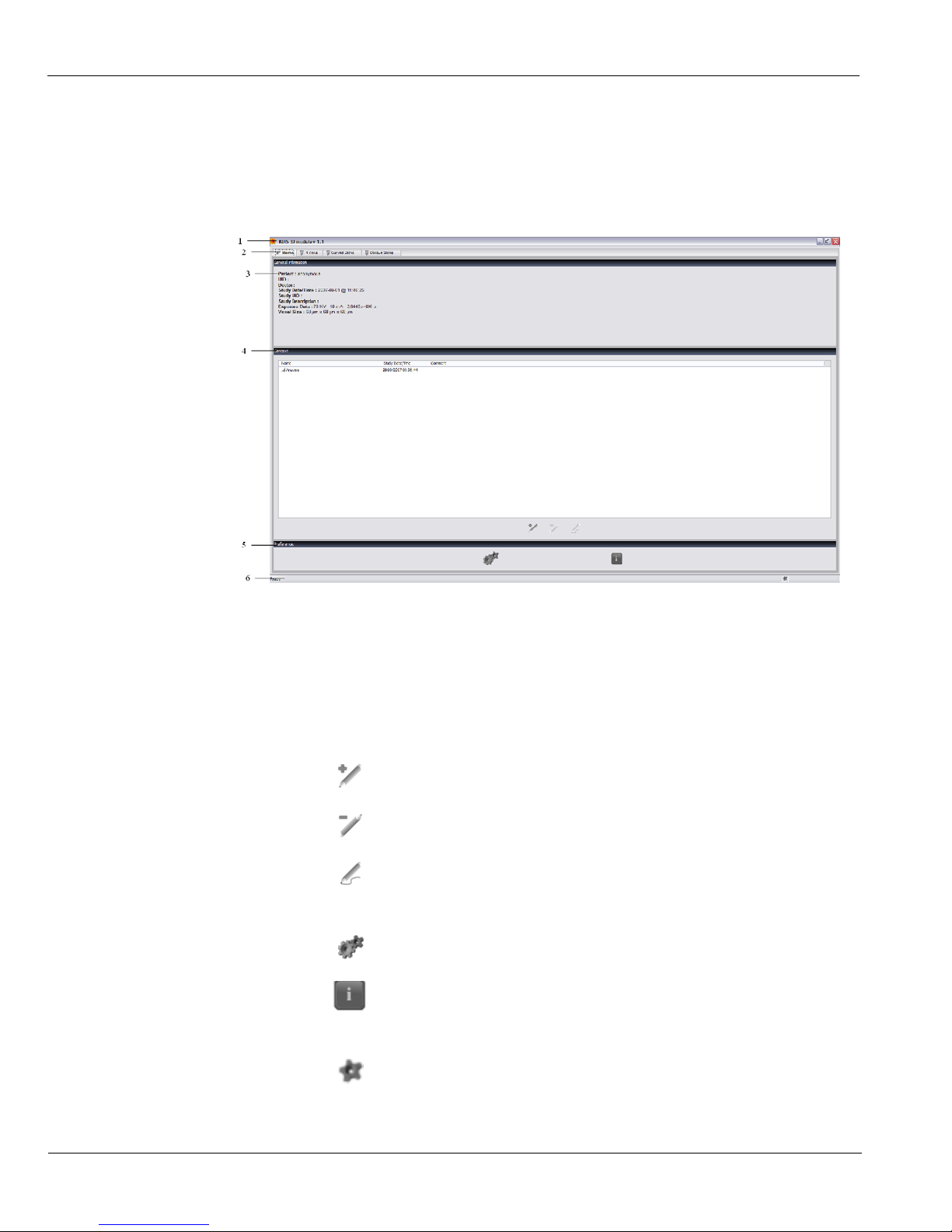
3D Imaging Windows Overview
The 3D Imaging Windows are the main imaging interfaces that provide you with the 3D
imaging functions.
Figure 3–3 3D Home Page Window
1 Title Bar: Displays Software name and version.
2 Window Tabs: Provide access to the indicated Windows.
3
General Information: Displays the 3D image acquisition information.
4 Context: Enables you to manage the patient 3D image analyses files.
• Click to create a new analyses file.
• Click to delete an analyses file.
• Click to edit an analyses file.
5 Preferences: Enables you to configure your settings.
• Click to configure the functional settings.
• Click to display the software version information.
6 Status bar: Informs the user about the status of the 3D Windows.
• Click to configure the functional settings.
Page 23
Kodak Dental Imaging Software Overview
KODAK 9000 3D Extraoral Imaging System_User Guide (SM710)_Ed 01 3–9
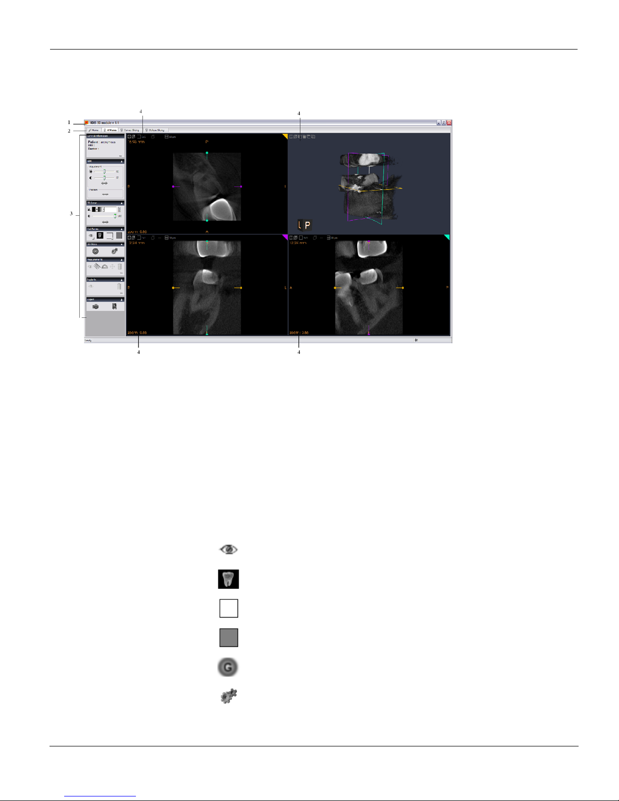
To access the 4 View Window, from the Home Page click the 4 View Window tab.
Figure 3–4 4 View Window
1Title Bar: Displays software name and version.
2Window Tabs: Provides access to the indicated windows.
3 Menu bar: provides access to the following functions:
Menu Submenu Description
General Information Displays the 3D image acquisition information
MPR (MultiPlanar
Reformat)
Adjustment Adjusts the slices contrast and brightness
Position Resets the cut planes position
3D Scene Adjusts the 3D view
Cut Planes
Click to show or hide the cut planes.
Click to display the cut plane as images.
Click to display the cut plane as wireframe.
Click to display the cut plane as colored planes.
3D Filters
Click to apply the smooth filter .
Click to configure the smooth filter settings.
Page 24
Kodak Dental Imaging Software Overview
3–10 IMAGING SOFTWARE OVERVIEW
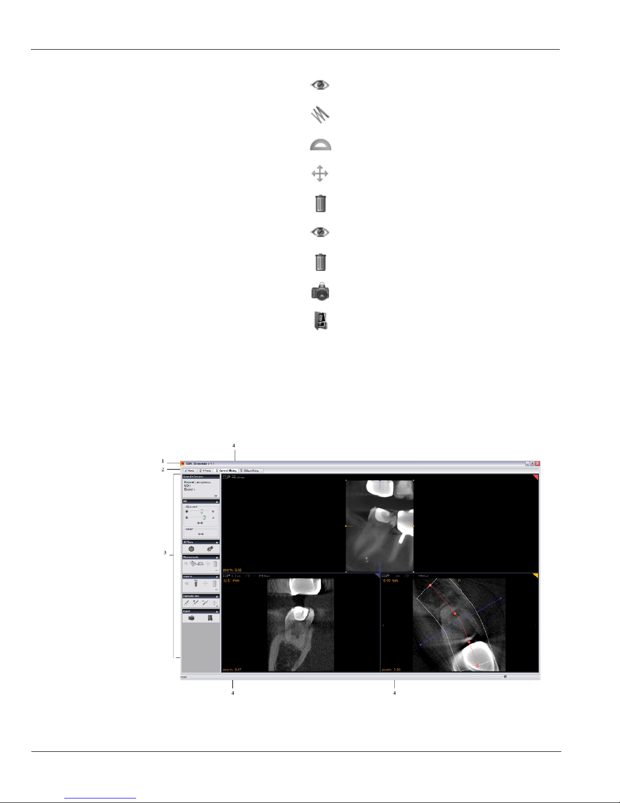
To access the Curved Slicing Window, from the Home Page click the Curved Slicing Window
tab.
Figure 3–5 Curved Slicing Wi nd ow
Measurements
Click to show or hide measurements.
Click to measure the length.
Click to measure the angle.
Click to edit the measurements.
Click to delete the measurements.
Implant
Click to show or hide all implant s.
Click to delete all implants.
Export
Click to create a screen capture file.
Click to access the screen capture file in the directory.
4 Display options: Display the specific screen in different formats.
1Title Bar: Displays software name and version.
Page 25
Kodak Dental Imaging Software Overview
KODAK 9000 3D Extraoral Imaging System_User Guide (SM710)_Ed 01 3–11
2 Window Tabs: Provides access to the indicated windows.
3 Menu bar: provides access to the following functions:
Menu Submenu Description
General Information
Displays the 3D image acquisition information.
MPR (MultiPlanar
Reformat)
Adjustment Adjusts the slices contrast and brightness.
Position Resets the cut planes position.
3D Filters
Click to apply the smooth filter.
Click to configure the smooth filter settings.
Measurements
Click to show or hide measurements.
Click to measure the length.
Click to measure the angle.
Click to edit the measurements.
Click to delete the measurements.
Implant
Click to show or hide all implants.
Click to add an implant.
Click to edit all implants.
Click to delete all implants.
Panoramic View
Click to create a curved line.
Click to add control points to the curved line.
Click to remove control points from the curved line.
Click to edit the curved line.
Export
Click to create a screen capture file.
Click to access the screen capture file in the directory.
4 Display options: Display the specific screen in different formats.
Page 26
Kodak Dental Imaging Software Overview
3–12 IMAGING SOFTWARE OVERVIEW
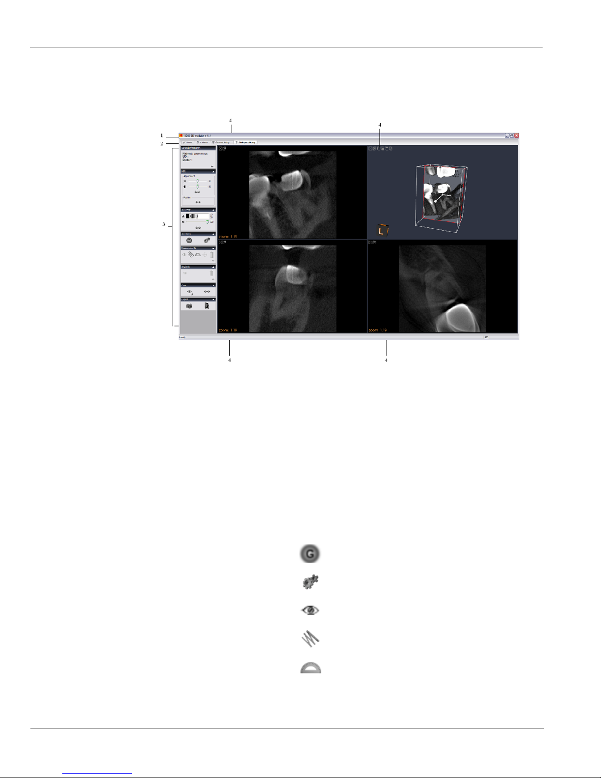
To access the Oblique Slicing Window, from the Home Page click the Oblique Slicing Window
tab.
Figure 3–6 Oblique Slicing Window
1 Title Bar: Displays software name and version.
2 Window Tabs: Provides access to the indicated windows.
3 Menu bar: Provides access to the following functions:
Menu Submenu Description
General Information
Displays the 3D image acquisition information.
MPR (MultiPlanar
Reformat)
Adjustment Adjusts the slices contrast and brightness.
Position Resets the cut planes position.
3D Scene Adjusts the 3D view.
3D Filters
Click to apply smooth filter.
Click to configure the smooth filter settings.
Measurements
Click to show or hide measurements.
Click to measure the length.
Click to measure the angle.
Page 27
Kodak Dental Imaging Software Overview
KODAK 9000 3D Extraoral Imaging System_User Guide (SM710)_Ed 01 3–13
Click to edit the measurements.
Click to delete the measurements.
Implant
Click to show or hide all im plants.
Click to delete all implants.
Crop
Click to show or hide the crop tool.
Export
Click to create a screen capture file.
Click to access the screen capture file in the directory.
4 Display options: Display the specific screen in different formats.
NOTE
Click
to use the default value.
Page 28
Acquisition Interface Module
3–14 IMAGING SOFTWARE OVERVIEW
Acquisition Interface Module
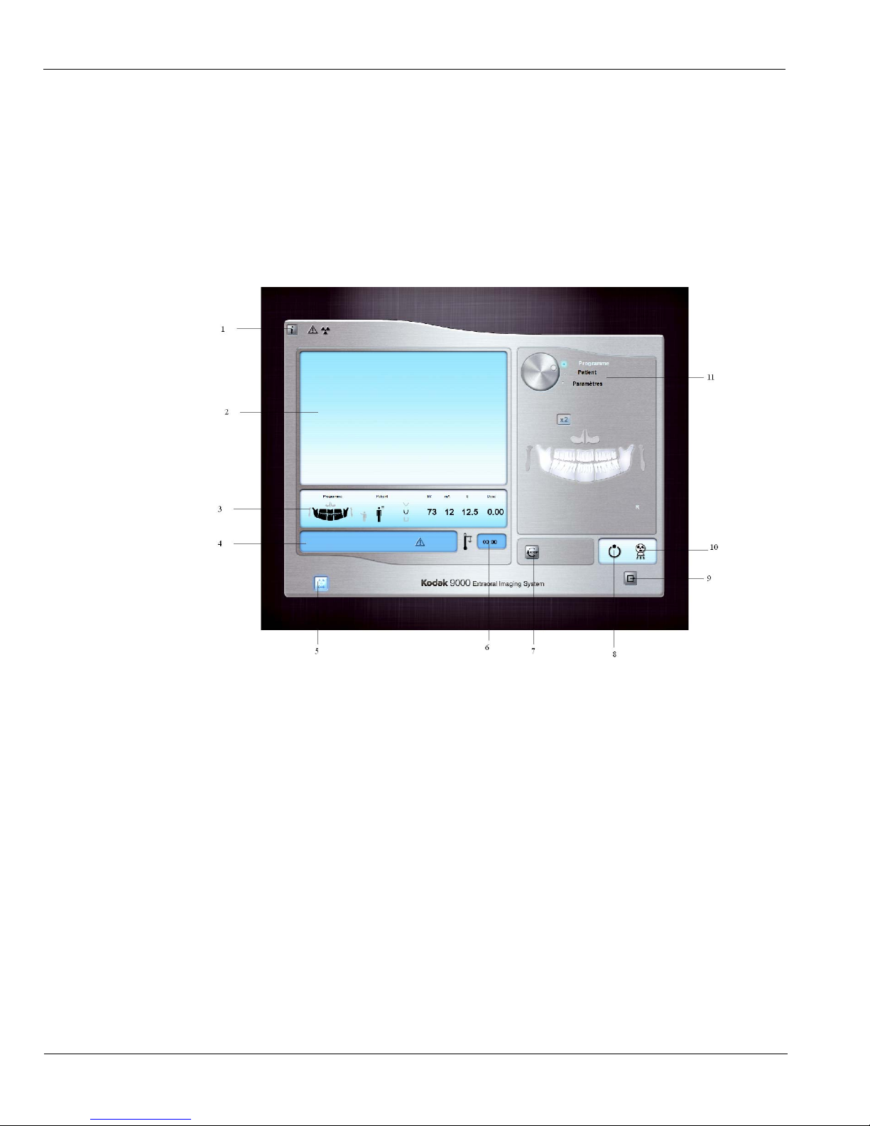
Panoramic Acquisition Window Overview
The Panoramic Acquisition Window is the main panoramic interface with the Kodak 9000
3D extraoral imaging system that provides you with imaging acquisition functions.
Figure 3–7 Panoramic Acquisition Window
1 Information button: identifies:
• Unit serial number
• Software version
• The default parameters set by the manufacturer
2 Preview Screen: Displays the acquired image in real time.
3 Selected Parameter Display: Displays the current acquisition parameter settings.
4 System Status Screen: Displays various alert or warning messages originating from the Unit.
5 X-Rays ON / OFF button: Turns off the x-ray emissions to demonstrate the acquisition process for
the patient.
6 Generator Cooling indicator: Indicates the automatic cooling time (mm:ss) required for the
generator to reach 0 for a new acquisition.
7 Stop button: Stops the Unit rotative arm movement
Page 29

Acquisition Interface Module
KODAK 9000 3D Extraoral Imaging System_User Guide (SM710)_Ed 01 3–15
The Selector button enables you to access the following 3 panes:
• Program pane: Examination type options
• Patient pane: Patient type parameter options
• Parameters pane: Exposure parameter options
8 Ready Indicator LED
• Green indicates the Unit is ready to start acquisition.
• Black indicates the Unit is not ready to start acquisition.
9 Exit button: Closes the Acquisition Window.
10 X-Ray Emission indicator: Yellow, it indicates the x-ray emission status.
11 Selector Button: Selects different acquisition setting options.
• Click Program to select examination type options.
• Click Patient to select patient type parameters.
• Click Parameters to select exposure parameter options.
Page 30
Acquisition Interface Module
3–16 IMAGING SOFTWARE OVERVIEW
Panoramic Program Pane
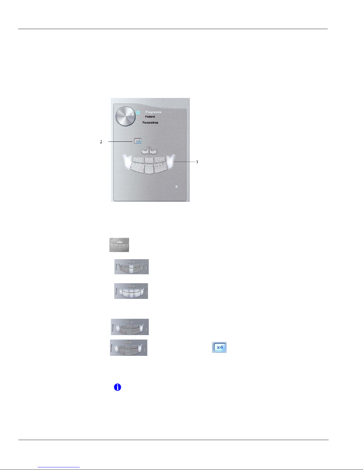
The Panoramic Program pane enables you to choose different radiological exams. The
diagram in the Panoramic Program pane represents a jaw, with the right side of the diagram
corresponding to the right side of the patient. Click on a section of the jaw to select an
anatomical zone for radiological exam. The selected segment is highlighted.
Figure 3–8 Panoramic Program Pane
1 Radiological exam options:
Click for a Maxillary Sinus exam.
Click
for an anterior exam.
Click for a Panoramic exam.
2
TMJ exam options:
Select for a TMJ x2.
Select for a TMJ x4 exam and click .
NOTE
The above list of exam types are only a sample of exam options of the
Program pane.
Page 31
Acquisition Interface Module
KODAK 9000 3D Extraoral Imaging System_User Guide (SM710)_Ed 01 3–17
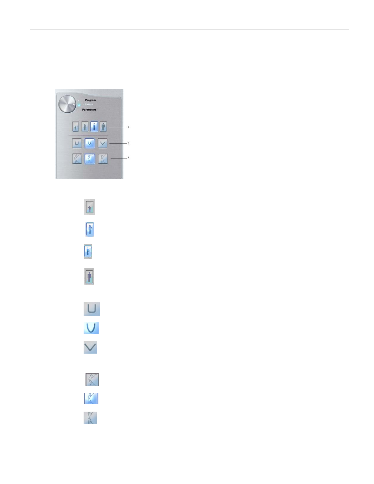
Panoramic Patient Pane
The Panoramic Patient pane enables you to choose different patient parameters. The selection
of the patient parameters influences the quality of the image. The selected parameters must be
based on the patient age and morphology.
Figure 3–9 Panoramic Patient Pane
1 Patient corpulence parameters:
Click if the patient is a child.
Click if the patient is small.
Click if the patient is medium.
Click if the patient is large.
2 Patient dental arch morphology:
Click for a square dental arch.
Click for a normal dental arch.
Click for a sharp dental arch.
3
Incisors orientation:
Click for a vestibular orientation.
Click for an axial orientation.
Click for a lingual orientation.
Page 32
Acquisition Interface Module
3–18 IMAGING SOFTWARE OVERVIEW
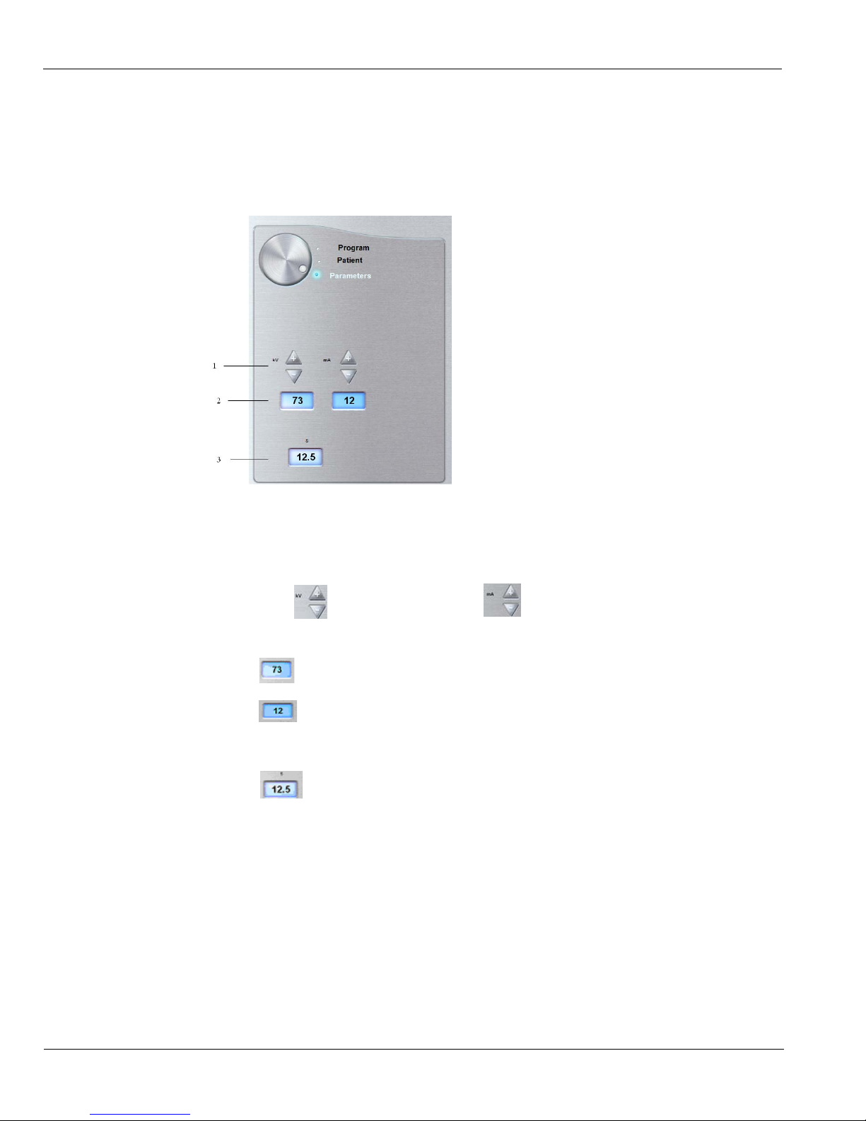
Panoramic Parameter Pane
The Panoramic Parameter pane enables you to choose exposure parameters for the
radiological image acquisition. You must adapt the parameter settings to the patient type.
Figure 3–10 Panoramic Parameter Pan
1
Fine-tuning buttons:
Click to fine-tune the kV and click to fine-tune the mA.
2 Radiation dose options:
Kilovolt
milliampere
3
Exposure time:
seconds
Page 33
Acquisition Interface Module
KODAK 9000 3D Extraoral Imaging System_User Guide (SM710)_Ed 01 3–19
3D Acquisition Window Overview
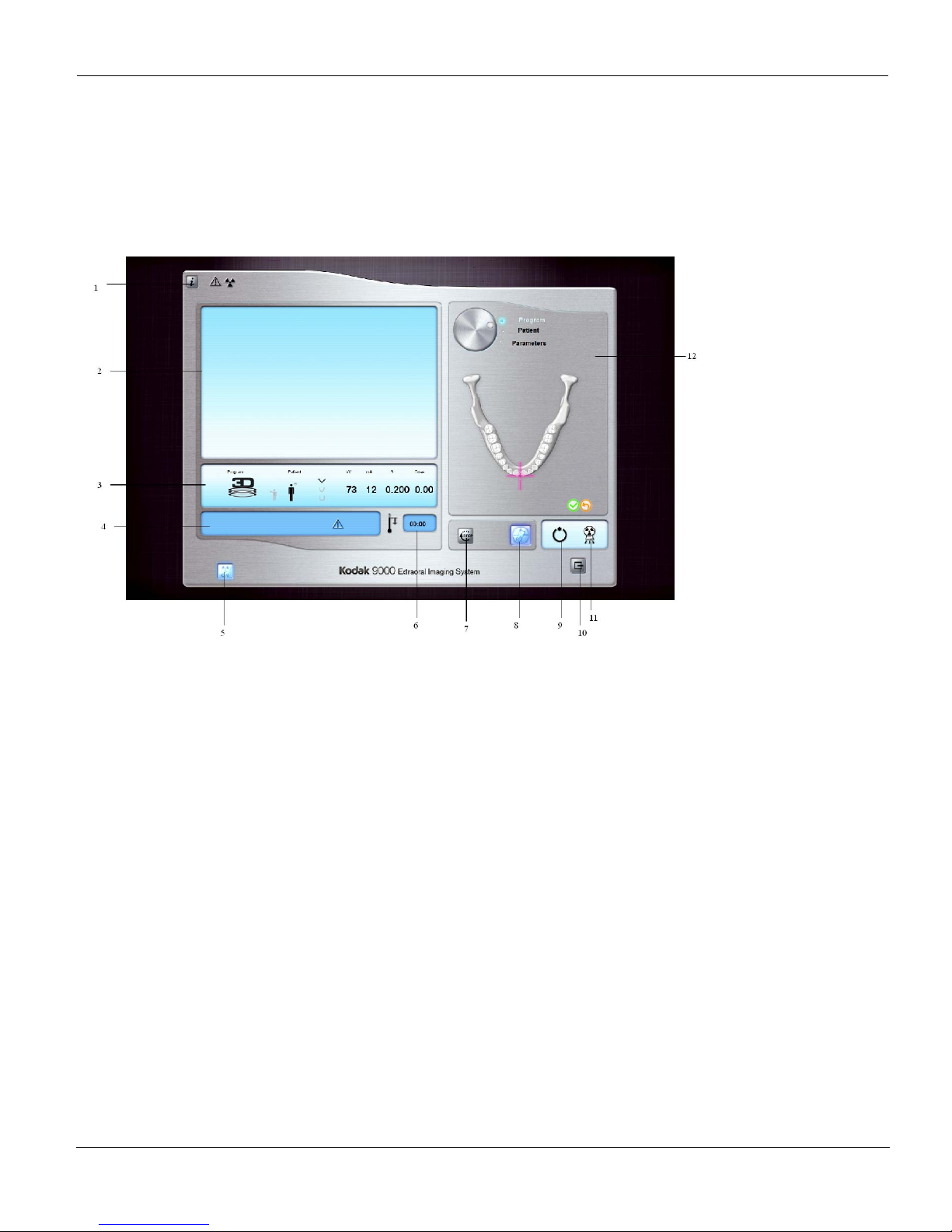
The 3D Acquisition Window is the main 3D interface with the Kodak 9000 3D extraoral
imaging system that provides you with imaging acquisition functions.
Figure 3–11 3D Acquisition Window
1 Information button: identifies:
• Unit serial number
• Software version
• Default parameters set by the manufacturer
2 Preview Screen: Displays the acquired image in real time.
3 Selected Parameter Display: Displays the current acquisition parameter settings.
4 System Status Screen: Displays various alert or warning messages originating from the Unit.
5 X-Rays ON / OFF button: Turns off the x-ray emissions to demonstrate the acquisition process for
the patient.
6 Generator Cooling indicator: Indicates the automatic cooling time (mm:ss) required for the
generator to reach 0 for a new acquisition.
7 Stop button: Stops the Unit rotative arm movement.
8 Pre-shoot button: Pre-acquires test images for correct selection of region of interest.
9 Ready Indicator LED:
• Green indicates the Unit is ready to start acquisition
• Black indicates the Unit is not ready to start acquisition
Page 34

Acquisition Interface Module
3–20 IMAGING SOFTWARE OVERVIEW
The Selector button enables you to access the following 3 panes:
• Program pane: Examination type options
• Patient pane: Patient type parameter options
• Parameters pane: Exposure parameter options
10 Exit button: Closes the Acquisition Window.
11 X-Ray Emission Indicator: Yellow indicates the x-ray emission status.
12 Selector button: Selects different acquisition setting options.
• Click Program to select examination type options
• Click Patient to select patient type parameters
• Click Parameters to select exposure parameter options
Page 35
Acquisition Interface Module
KODAK 9000 3D Extraoral Imaging System_User Guide (SM710)_Ed 01 3–21
3D Program Pane
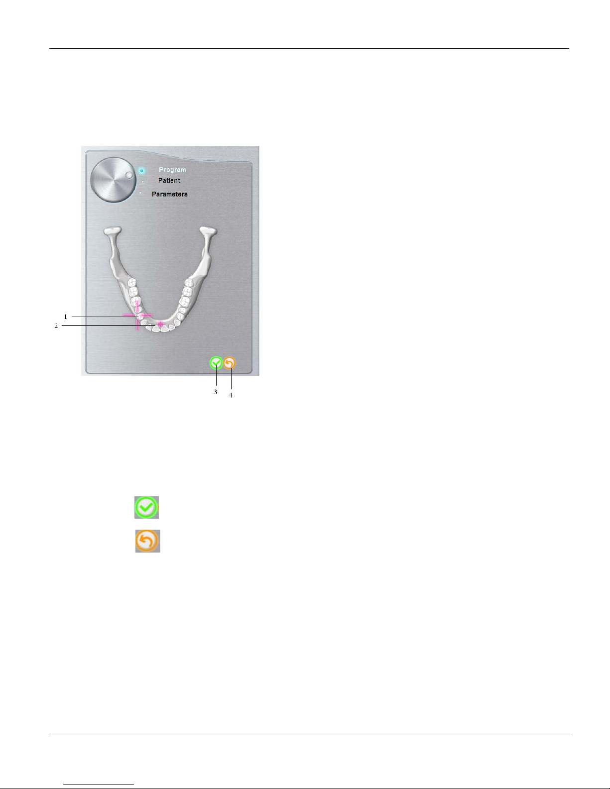
The 3D Program pane enables you to choose different radiological exams. The diagram in
the Program pane represents the jaw.
Figure 3–12 3D Program Pane
1 Manual Selection Indicator: Enables you to select the region of interest
manually.
2 Rotative Arm Position Indicator: Indicates the rotative arm position, using the
3D central positioning laser beam.
3
Click to validate the region of interest selection.
4
Click to cancel the region of interest selection.
Page 36
Acquisition Interface Module
3–22 IMAGING SOFTWARE OVERVIEW
3D Patient Pane
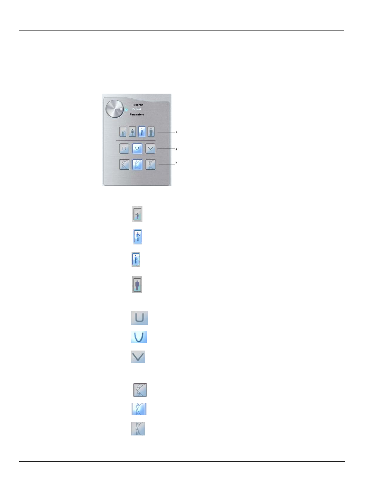
The 3D Patient pane enables you to choose different patient parameters. The selection of the
patient parameters influences the quality of the image. The selected parameters must be based
on the patient age and morphology.
Figure 3–13 Panoramic Patient Pane
1 Patient corpulence parameters:
Click if the patient is a ch ild.
Click if the patient is small.
Click if the patient is medium.
Click if the patient is large.
2 Patient dental arch morphology:
Click for a square dental arch.
Click for a normal shape dental arch.
Click for a sharp dental arch.
3
Incisors orientation:
Click for a vestibular orientation.
Click for an axial orientation.
Click for a lingual orientation.
Page 37
Acquisition Interface Module
KODAK 9000 3D Extraoral Imaging System_User Guide (SM710)_Ed 01 3–23
3D Parameter Pane
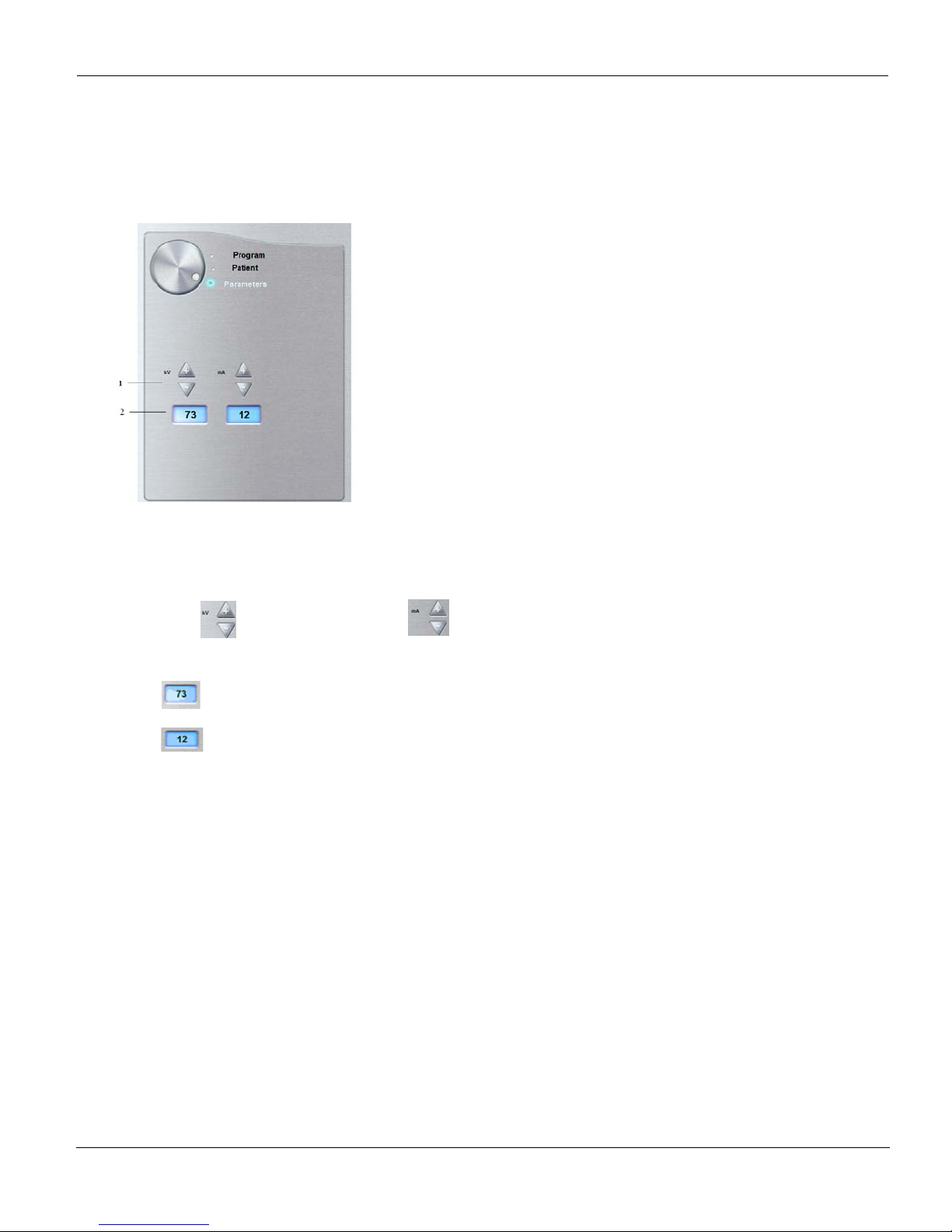
The 3D Parameter pane enables you to choose exposure parameters for the radiological
image acquisition. You must adapt the parameter settings to the patient type.
Figure 3–14 3D Parameter Pane.
1
Fine-tuning buttons:
Click to fine-tune the kV and click to fine-tune the mA.
2 Radiation dose options:
Kilovolt
milliampere
Page 38

Acquisition Interface Module
3–24 IMAGING SOFTWARE OVERVIEW
Page 39
KODAK 9000 3D Extraoral Imaging System_User Guide (SM710)_Ed 01 4–1
Chapter 4
GETTING STARTED
Starting the Imaging Software
Before starting your imaging software, check that:
• All the connections between the Unit and the PC are properly connected.
• The PC is turned ON.
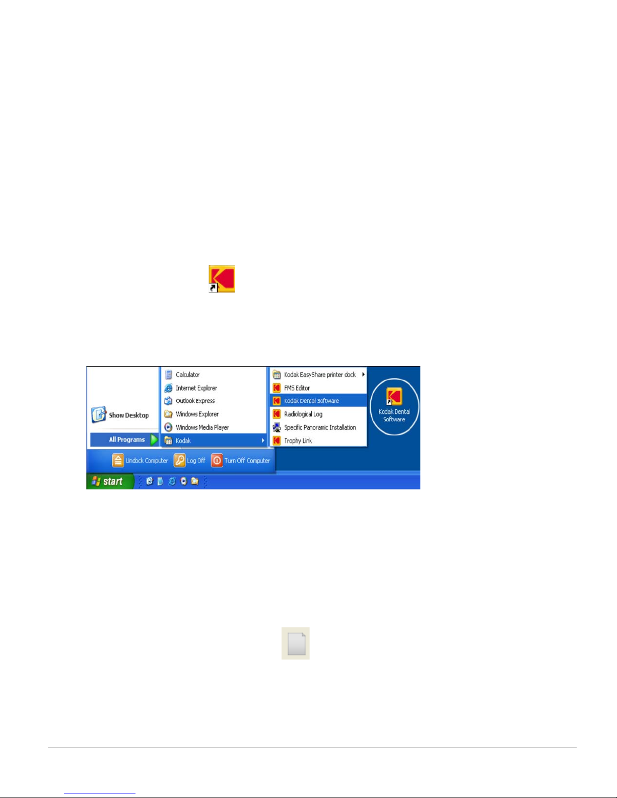
To start your imaging software, follow these steps:
1. On your desktop, double-click
OR
From your PC, click Start > All Programs > Kodak > Kodak Dental Software.
Blank Patient Window is displayed.
2. Create or open an existing patient record.
Creating a Patient Record
To create a patient record, follow these steps:
1. In the Patient Window, from the toolbar, click
OR
From the menu bar, select Patient > New.
Page 40
Accessing the Acquisition Windows
4–2 GETTING STARTED
2. Enter the required patient information. The Last name, the First name and the Date of
birth fields are required.
3. From the menu ba r, select Picture > Insert Picture to add a *.tif or *.bmp picture of the
patient to the record. Select the picture from your directory and click Open.
4. Click OK to save. The patient record is automatically assigned a 7-digit number starting
with a letter (for example, M0000001).
5. Click to access the Imaging Window.
6. Select an image acquisition.
Accessing the Acquisition Windows
To access the Acquisition Windows, follow these steps:
1. In the Imaging Window, from the toolbar, click to access the Panoramic
Acquisition Window, or, click to access the 3D Acquisition Window.
2. Prepare the acquisition parameters and launch an acquisition.
Switching On the Unit
Before switching on the Unit, check that the installation of the Unit is complete.
To switch on the Unit, follow these steps:
1. On the Unit column, press the ON button. The name of the patient appears in the Display
Screen of the Control Panel.
IMPORTANT
T o incr ease the operating life of the x-ray tube, if the Unit has not been used
for a month, you must follow these following procedures before use.
2. In the Panoramic Acquisition Window, select the Parameter pane.
3. Select the following parameter settings; then, for each setting, from the Remote Control,
press and hold the button to launch the x-ray:
• 70 kV - 6.3 mA
• 80 kV - 10 mA
• 85 kV - 10 mA
The Unit is now ready to be used for acquisition.
Page 41

KODAK 9000 3D Extraoral Imaging System_User Guide (SM710)_Ed 01 5–1
Chapter 5
ACQUIRING IMAGES
Acquiring a Panoramic, TMJ x2 or Sinus Image
Before acquiring an image, check that you have:
• Reset the Unit rotative arm to start position for patient entry
• Selected the patient record
• Accessed the Imaging Window
• Accessed the Panoramic Acquisition Window
Preparing the Unit and Setting the Acquisition
Parameters
To set the acquisition parameters, follow these steps:
1. In the Panoramic Acquisition Window, click the Program button to access the Program
pane. Click on the section of the jaw to select the anatomical zone for the x-ray image,
such as panoramic, TMJ x2 or sinus.
2. Click the Patient button to access the Patient pane.
Select the patient:
• Corpulence
• Dental arch morphology
• Incisors orientation
3. If needed, click the Parameter button to access the Parameter pane and select the
appropriate parameters.
4. Position the appropriate chin rest on the chin rest support and cover the bite block with a
hygienic barrier. If needed, use the edentulous bite block. Press and hold to raise
the chin rest to the maximum height.
Page 42
Acquiring a Panoramic, TMJ x2 or Sinus Image
5–2 ACQUIRING IMAGES
Preparing and Positioning the Patient
To prepare and position the patient, follow these steps:
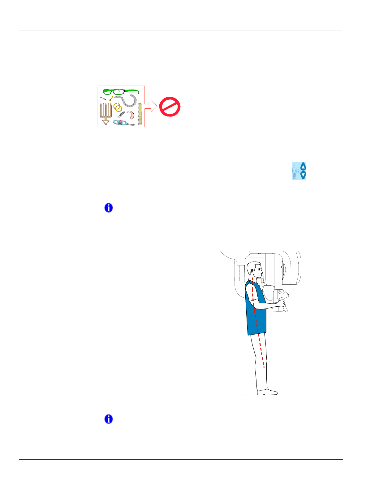
1. Ask the patient to remove all metal objects.
2. Ask the patient to wear a lead apron. Ensure that the apron lays flat across the patient
shoulders.
3. Ask the patient to enter the Unit. On the Control Panel, press and hold to adjust the
Unit to the patient height.
4. Ask the patient to do the following:
NOTE
If the patient is too tall, ask the patient to sit on a stool.
• Stand up straight.
• Grip the lower handle on each side.
• Rest the chin on the chin rest support and
bite into the bite block.
• Position the feet slightly forward.
• Relax the shoulders for full motion of the
Unit rotative arm.
NOTE
Correct posture reduces the shadow of the spinal column transferred
to the image.
Page 43
Acquiring a Panoramic, TMJ x2 or Sinus Image
KODAK 9000 3D Extraoral Imaging System_User Guide (SM710)_Ed 01 5–3
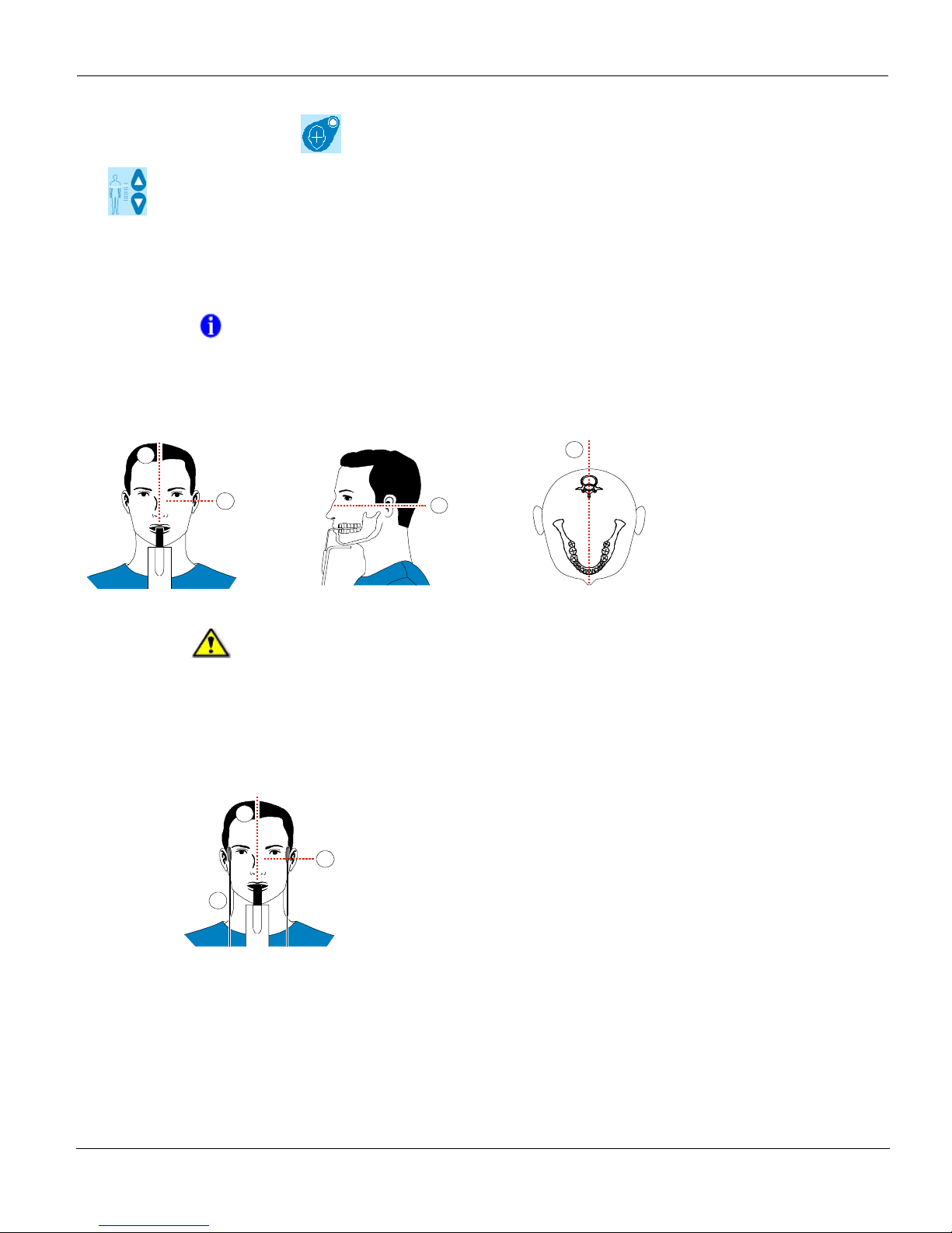
5. On the Control Panel click to turn ON the positioning laser beams. Press and hold
to correctly position the patient using the 2 positioning laser beams:
• The mid-sagittal (1) positioning laser beam for a vertical alignment.
• The horizontal (2) positioning laser beam for a Frankfurt plane alignment.
6. Immobilize the patient head with the temple supports (3).
NOTE
You can re-activate the laser positioning beams as needed. You can
press the same button to turn OFF the laser beams, or wait 60 seconds
for the beams to turn OFF automatically.
IMPORTANT
The spinal column and the nose of the patient must be aligned in a
straight line (1).
2
1
2
1
2
1
3
Page 44
Acquiring a Panoramic, TMJ x2 or Sinus Image
5–4 ACQUIRING IMAGES
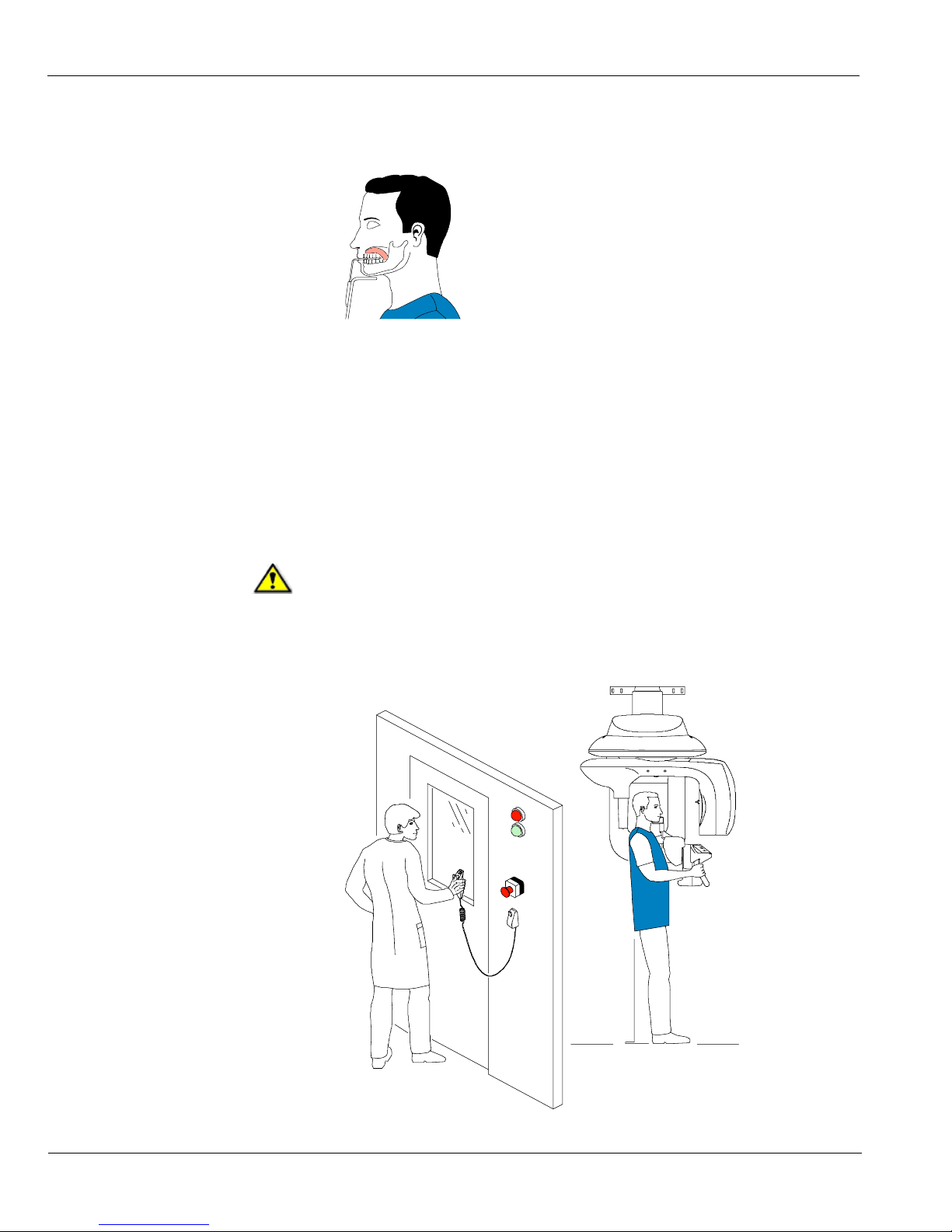
7. Ask the patient to close the eyes, to remain still, to swallow, to place the tongue in contact
with the palate and to breath through the nose.
Launching the X-ray
To launch the x-ray, follow these steps:
1. Leave the x-ray room and close the door. You must keep eye contact with the patient
during acquisition.
IMPORTANT
To stop the acquisition, if any problem, release the exposure
button of the remote control or press the red emergency stop
button.
Page 45

Acquiring a Panoramic, TMJ x2 or Sinus Image
KODAK 9000 3D Extraoral Imaging System_User Guide (SM710)_Ed 01 5–5
2. Launch the x-ray with the remote control. Press and hold the exposure button until the end
of acquisition. The turns yellow indicating x-ray emission. The image appears on the
Preview Screen of the Panoramic Acquisition Window. When the acquisition ends, the
Panoramic Acquisition Window disappears and the acquired image is automatically
transferred to the Imaging Window.
3. Check the image quality .
4. Do the following when the acquisition is finished:
• Open the temple supports and release the patient.
• Remove the hygiene barrier of the bite block.
• Reset the Unit rotative arm for the next acquisition.
Page 46
Acquiring a TMJ x4 Image
5–6 ACQUIRING IMAGES
Acquiring a TMJ x4 Image
Before acquiring a TMJ x4 image, check that you have:
• Reset the Unit rotative arm to start position for patient entry
• Selected the patient record
• Accessed the Imaging Window
• Accessed the Panoramic Acquisition Window
To acquire a TMJ x4 image, follow these steps:
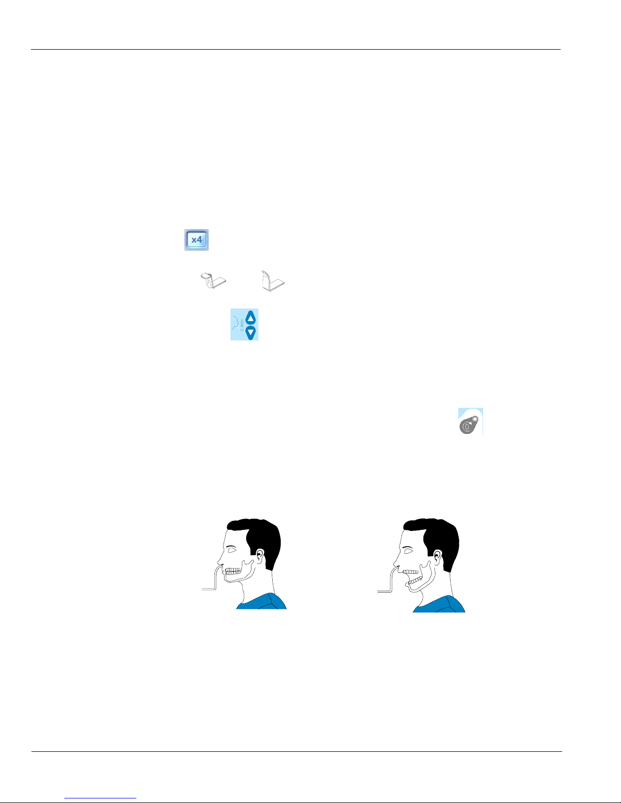
1. From the Panoramic Acquisition Window, in the Program pane, select the TMJ and
click .
2. Remove , place on the chin rest support and cover it with a hygienic barrier.
3. Press and hold to raise the chin rest to the maximum height.
4. Correctly position the patient using the 2 positioning laser beams.
5. Ask the patient to remain still and close the eyes. Acquire an image with the mouth closed.
6. To acquire an image with open mouth, on the Control Panel click to reset the Unit
rotative arm.
7. Ask the patient to stay in the same position and open the mouth. Acquire an image with
the mouth open.
8. Do the following when the acquisition is finished:
• Open the temple supports and release the patient.
• Remove the hygiene barrier of the bite block.
• Reset the Unit rotative arm for the next acquisition.
Page 47
Acquiring a 3D Image
KODAK 9000 3D Extraoral Imaging System_User Guide (SM710)_Ed 01 5–7
Acquiring a 3D Image
Before acquiring a 3D image, check that you have:
• Reset the Unit rotative arm in start position for patient entry
• Selected the patient record
• Accessed the Imaging Window
• Accessed the 3D Acquisition Window
Preparing the Unit and Setting the Acquisition
Parameters
To set the acquisition parameters, follow these steps:
1. In the 3D Acquisition Window, click the Program button to access the Program pane.
Select the region of interest and click to validate the selection, or click
to
cancel the modifications.
2. Click the Patient button to access the Patient pane.
Select the patient:
• Corpulence
• Dental arch morphology (optional)
• Incisors orientation (optional)
3. Click the Parameter button to access the Parameter pane. Select the appropriate
parameters.
4. Position the 3D head rest and 3D standard bite block and cover the bite block with a
hygienic barrier.
Preparing and Positioning the Patient
To prepare and position the patient, follow these steps:
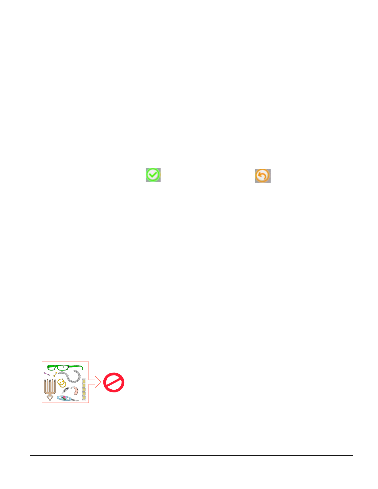
1. Ask the patient to remove all metal objects.
2. Ask the patient to wear a lead apron. Ensure that the apron lays flat across the patient
shoulders.
Page 48
Acquiring a 3D Image
5–8 ACQUIRING IMAGES
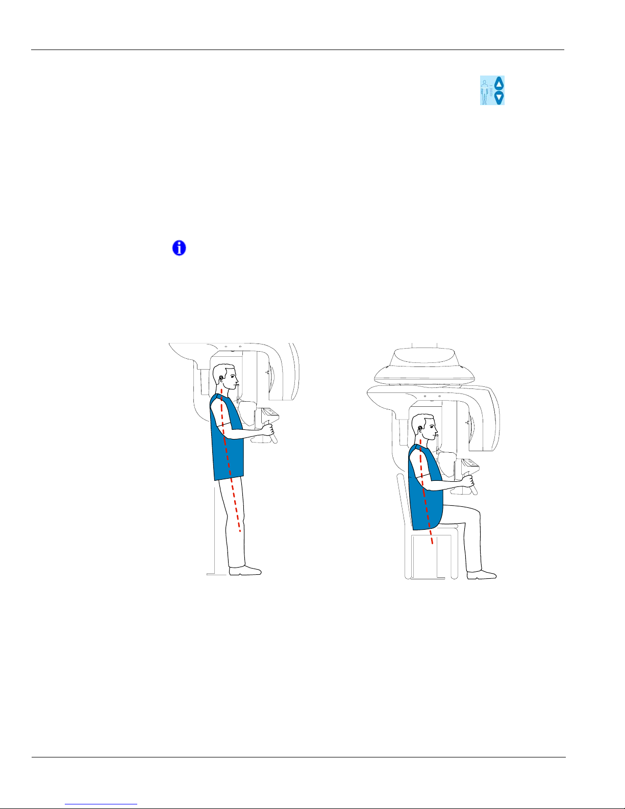
3. Ask the patient to enter the Unit. On the Control Panel, press and hold to adjust the
Unit to the patient height.
4. Ask the patient to do the following:
• Stand up straight or sit on a stool.
• Grip the lower handle on each side.
• Position the feet slightly forward.
• Relax the shoulders for full motion of the Unit rotating Arm.
:
5. Position the patient head in the 3D head support.
• Ask the patient to open the mouth.
• Ask the patient to bite gently and naturally into the bite block without joining the
incisors.
• Center the upper incisors with the bite block.
NOTE
If the patient is too tall, ask the patient to sit on a stool.
Page 49
Acquiring a 3D Image
KODAK 9000 3D Extraoral Imaging System_User Guide (SM710)_Ed 01 5–9
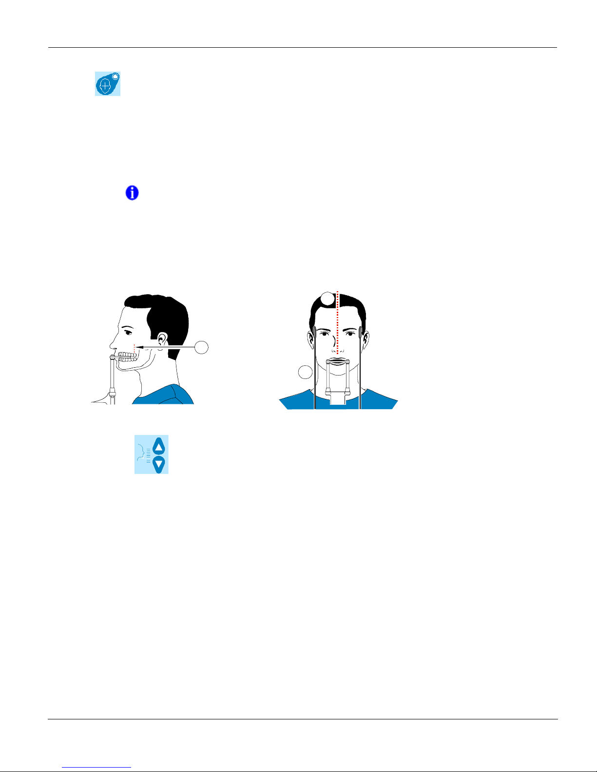
6. Click on the Control Panel to turn ON the positioning laser beams. Adjust the
patient using the following 2 positioning laser beams:
• The mid-sagittal (1) positioning laser beam
• The 3D FoV (2) positioning laser beam
7. Press and hold to align the upper or lower jaw with the 3D FoV (2) positioning
laser beam. Tighten the temple supports (3).
8. Ask the patient to close the eyes, to remains still and to breath through the nose.
NOTE
You can re-activate the laser positioning beams as needed. You can
press the same button to turn OFF the laser beams, or wait 60 seconds
for the beams to turn OFF automatically.
2
1
3
Page 50
Acquiring a 3D Image
5–10 ACQUIRING IMAGES
Launching the x-ray
To launch the x-ray, follow these steps:
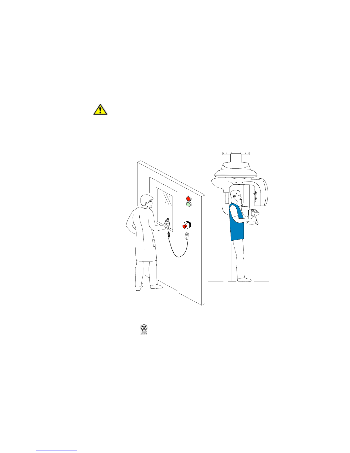
1. Leave the x-ray room and close the door. You must keep eye contact with the patient
during acquisition.
2. Trigger the x-ray with the remote control. Press and hold the exposure button until the end
of acquisition. The turns yellow indicating x-ray emission. The image appears in the
Preview Screen. When the acquisition ends, the 3D Acquisition Window disappears.
3. Open the 3D head support and release the patient while waiting for the 3D image
reconstruction. Remove the hygiene barrier of the bite block.
4. Wait for the 3D image reconstruction. Open the Imaging Window and
IMPORTANT
To stop the acquisition, if any problem, release the exposure
button of the remote control or press the red emergency stop
button.
Page 51
Acquiring a 3D Image
KODAK 9000 3D Extraoral Imaging System_User Guide (SM710)_Ed 01 5–11
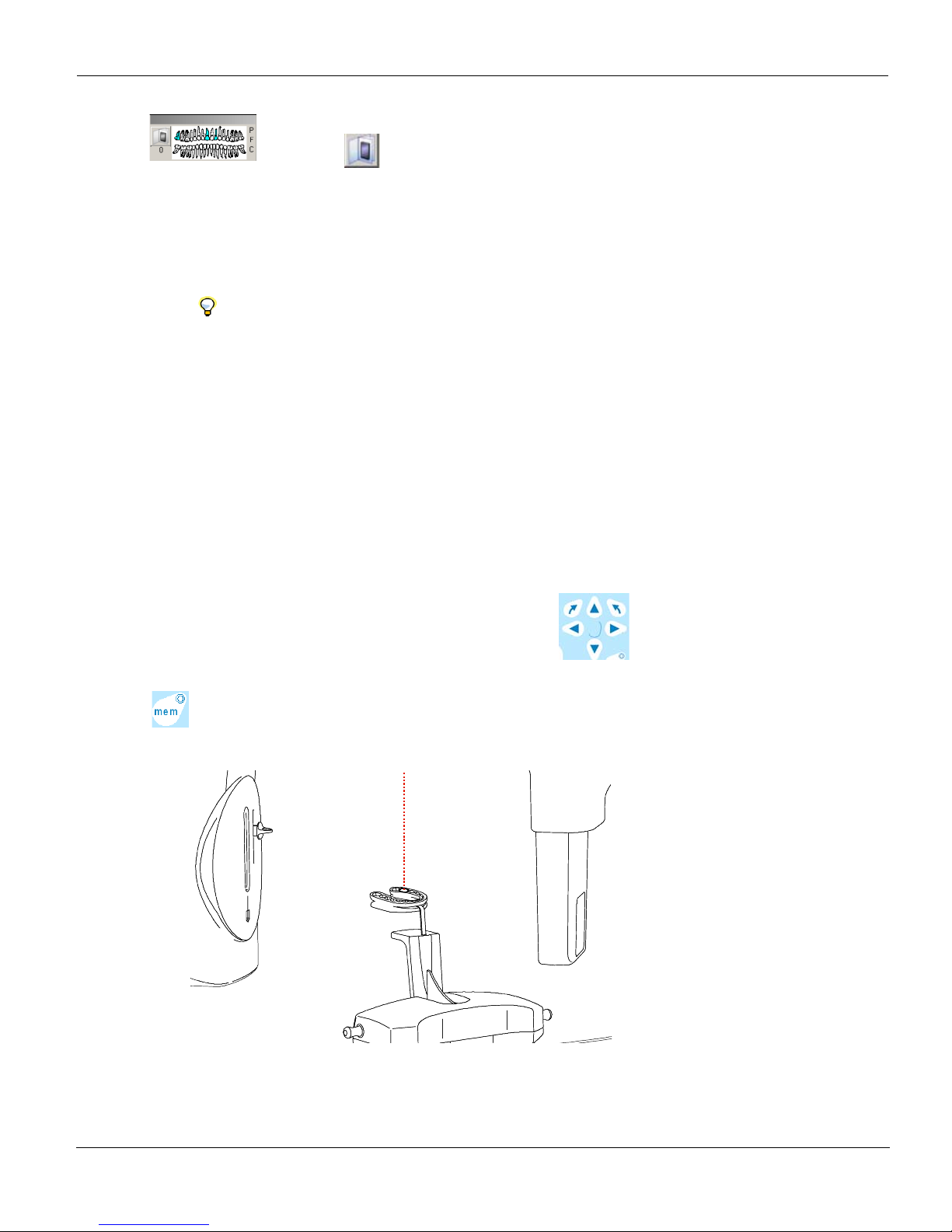
in the pane, click to access the patient record and open the
acquired 3D image.
Manually Pre-Setting the Patient Positioning
To pre-set the acquisition parameters, follow these steps:
1. Select the appropriate settings in:
• The Program pane
• The Patient pane
• The Parameter pane if needed
2. To pre-set the patient positioning, ask the patient to bite into a plate of dental plaster and
wait for the plaster imprint to harden.
3. Place the dental imprint on the bite block location. Press and hold to align the
Unit rotative arm to the region of interest using the 3D central positioning laser beam.
Press to save the manually selected parameter settings of the Unit rotative arm.
4. Remove the plaster imprint and position the patient in the Unit and follow the appropriate
steps to acquire the 3D image of the region of interest.
TIP
You can pre-set the acquisition parameters of the region of interest
manually using dental plaster imprint.
Page 52

Acquiring a 3D Image
5–12 ACQUIRING IMAGES
Page 53
KODAK 9000 3D Extraoral Imaging System_User Guide (SM710)_Ed 01 6–1
Chapter 6
MAINTENANCE
This section describes the maintenance tasks that you need to perform regularly for your
KODAK 9000 3D Unit and the accessories.
Daily
Carry out the following maintenance tasks:
Monthly
Wipe the outer covers of the unit with a soft, dry cloth.
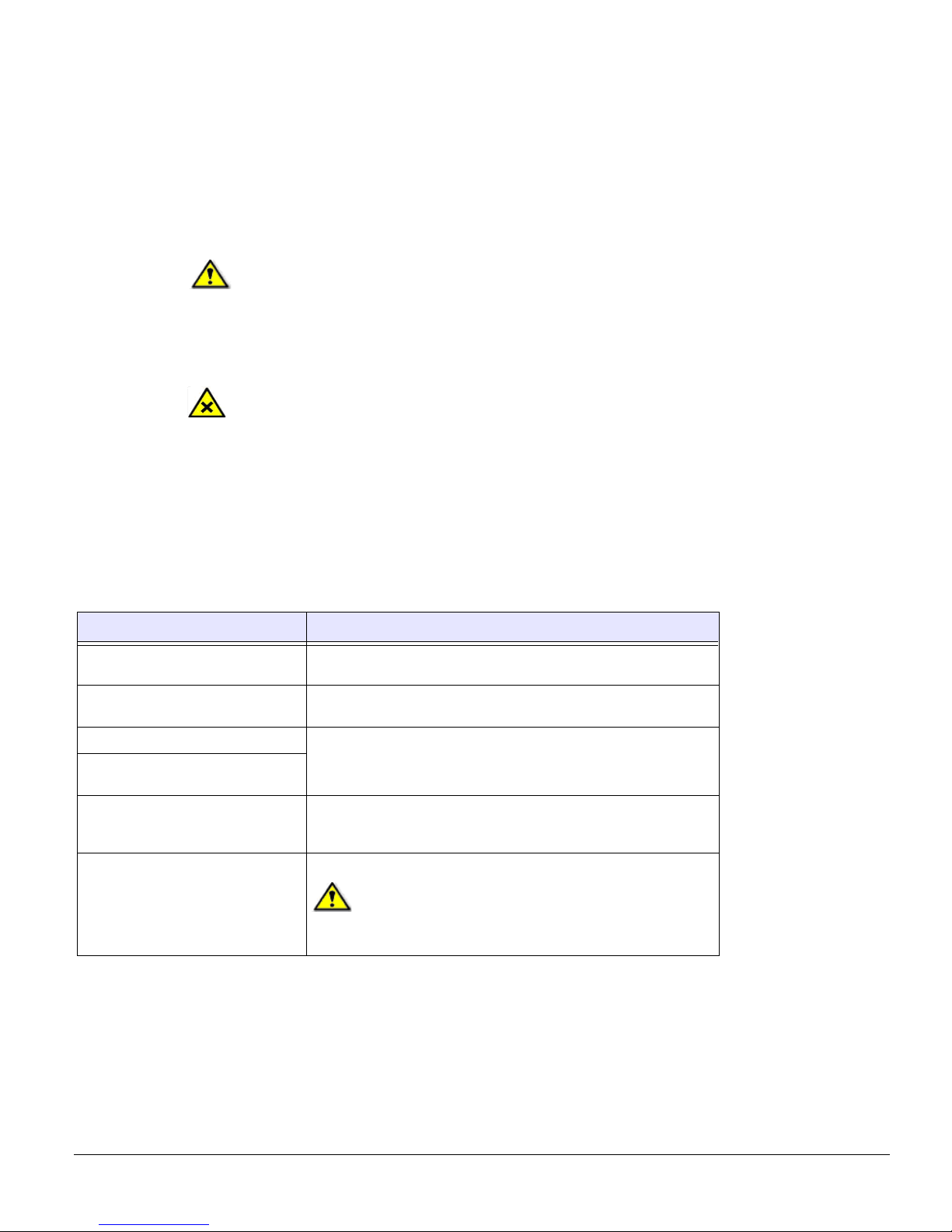
WARNING
Switch off the Unit, then, clean all accessible parts of the machine
with an alcohol-based non-corrosive product. Avoid using liquids
inside the Unit. Follow the alcohol-based product manufacturer
recommendations for safety precautions.
CAUTION
You can use the usual disinfectant products, but we recommend
that you protect the Unit from contamination by using barriers
available from dental distributors. Follow the disinfectant
product manufacturer recommendations for safety precautions.
Table 6–1 Daily Maintenance Tasks
Accessories Maintenance Tasks
3D and Panoramic bite block Sterilize with cold sterilization or autoclave up to 134°C before the next
patient is x-rayed.
Edentulous bite block Sterilize with cold sterilization or autoclave up to 134°C before the next
patient is x-rayed.
Temple support Sterilize the head support and chin rest with medical-grade 76% alcohol
disinfectant before the next patient is x-rayed.
Chin rest (panoramic, sinus and
TMJ)
All components that come into
contact with the patient and the
operator
Sterilize all components with medical-grade 76% alcohol disinfectant
before the next patient is x-rayed.
Outer covers of the Unit Wipe the Unit with a dry cloth at the end of each day's operation.
WARNING
Do not use detergents or solvents to clean the outer covers of the
Unit.
Page 54

Annually
6–2 MAINTENANCE
Annually
We recommend a general inspection of the Unit carried out by an authorized service
technician.
Page 55

KODAK 9000 3D Extraoral Imaging System_User Guide (SM710)_Ed 01 7–1
Chapter 7
TECHNICAL SPECIFICATIONS
Compliance with International Standards
The KODAK 9000 3D digital imaging Unit is compliant with the International and EEC
standards.
Manufacturer
TROPHY
A subsidiary of Carestream Health, Inc.
4, Rue F. Pelloutier, Croissy-Beaubourg
77435 Marne la Vallée Cedex 2, France
Model
KODAK 9000 3D Unit, KODAK 9000 Unit.
Compliance with International Regulations
• Medical Device directives 93/42/ European Economic Community (EEC), Class II b
• ElectroMagnetic Compatibility (EMC) directive 89/336/EEC
Compliance with International Standards
• International Electrotechnical Commission (IEC) 60601-1 Class I Type B
• IEC 60601-1-2, Group I, Class B +12db
• IEC 60601-1-3
• IEC 60601-2-7
• IEC 60601-1-28
Ambient Operating Conditions
• Temperatures: 5 ~35 °C
• Relative humidity: 30 ~ 85%
• Atmospheric pressure: 700 ~ 1060 hpa
Storage Conditions
• Temperatures: -10 ~ 60 °C
• Relative humidity: 10 ~ 95%
• Atmospheric pressure: 700 ~ 1060 hpa
Transport Conditions
• Temperatures: -10 ~ 60 °C
• Relative humidity: 10 ~ 95%
• Atmospheric pressure: 700 ~ 1060 hpa
Page 56

Unit Technical Specifications
7–2 TECHNICAL SPECIFICATIONS
Unit Technical Specifications
Table 8-1 describes the technical specifications for the KODAK 9000 3D digital imaging unit
and Kodak 9000 digital imaging unit.
Table 7–1 Unit Technical Specification
Kodak 9000 3D Kodak 9000
X-Ray Generator
Tube voltage 60 - 90 kV (max), pulsed mode for 3D modality
Tube current 2 - 15 mA (max)
Frequency 140 kHz (max)
Tube focal spot 0.5 mm (IEC 60336)
Total filtration > 2.5 mm eq. Al
3D Modality
Technology Digital Volumetric Tomography (DVT) NA
Sensor technology
• CMOS
• Optical fiber sensor with Csi
coating
NA
Gray scale 16384 - 14 bits NA
Volume size 50 x 37 mm NA
Voxel size 76.5 x 76.5 x 76.5 µm NA
Reconstruction time Depends on the PC NA
X-ray pulse time 30 ms
Panoramic Modality
Sensor technology
• CCD
• Optical fiber sensor with Csi coating
Sensor matrix 61 x 1244 pixels
Image field 6.3 x 129.4 mm
Gray scale 16384 - 14 bits
Magnification 1.27
Exposure time
• Adult panoramic 13.9 sec.
• Pediatric panoramic 13.2 sec.
Programs 12 anatomical settings
Radiological exam options
• Panoramic
• Segmented panoramic
• Maxillary sinus
• LA TMJ x2
• LA TMJ x4
Page 57

Unit Technical Specifications
KODAK 9000 3D Extraoral Imaging System_User Guide (SM710)_Ed 01 7–3
Input voltage
• 230 / 240 V - 50/60 Hz
• 100/110/130 V - 50/60 Hz
Unit dimensions 1158mm (L) x 1595mm (D) x 2378mm (H)*
* Unit with shorter column is available on special order
Required space 1500 (L) x 2000 (D) x 2400 (H) mm
Weight
160 kg (353 lb
)
Table 7–1 Unit Technical Specification
Kodak 9000 3D Kodak 9000
Page 58
Unit Electronic Specifications
7–4 TECHNICAL SPECIFICATIONS
Unit Electronic Specifications
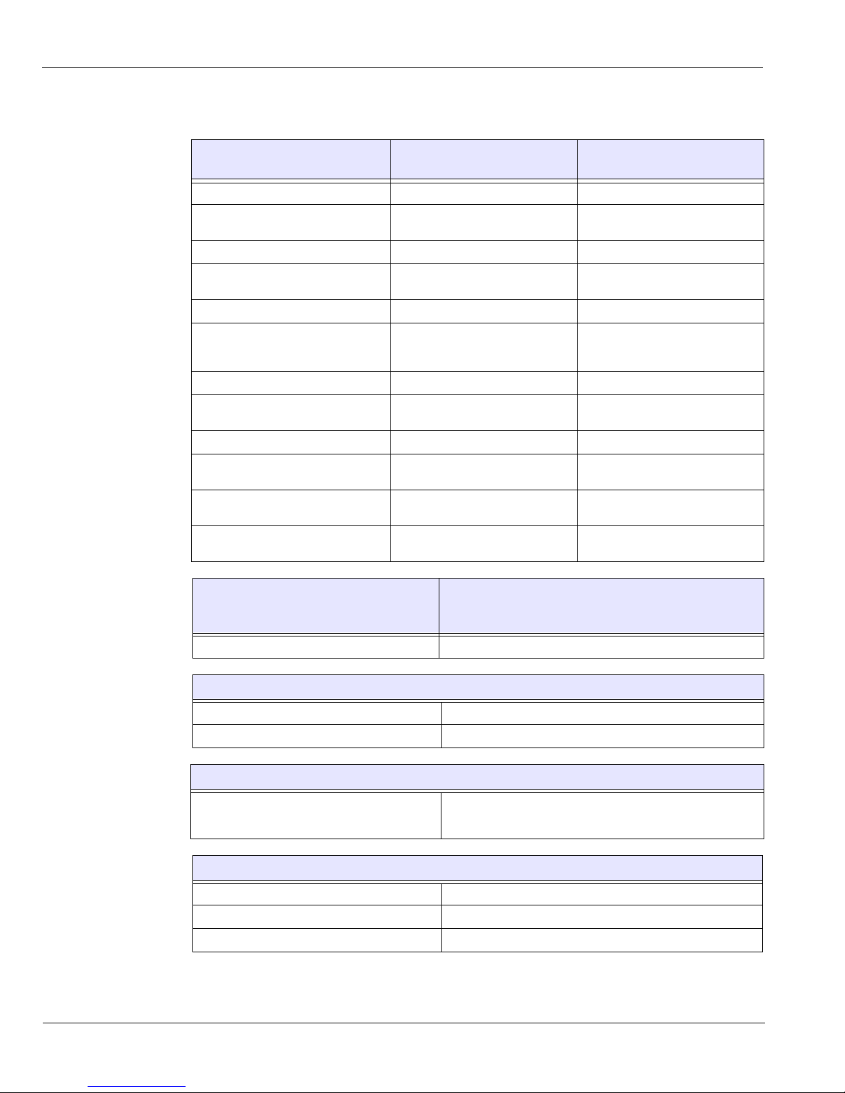
Type of Electrical Power Supply
230/240 V (± 10%) 50/60 Hz,
Single-Phase
100/110/130V (± 10%) 50/60 Hz,
Single-Phase
Acceptable fluctuation ± 10% ± 10%
Apparent resistance of the power
supply circuit
0.5
(max.) 0.12 (max.)
Permanent absorbed current 0.45 A 0.9 A
Current absorbed during the x-ray
emission
9.5 A 22 A
Maximum absorbed power 2.2 kVA 2.2 kVA
Protection for the power supply
system
By shutter release at a maximum
current of 16A and a differential
current of 30 mA
By shutter release at a maximum
current of 20A and a differential
current of 30 mA
Nominal high voltage 90 kV 90 kV
Maximum corresponding tube
current
10 mA 10 mA
Nominal tube current 15 mA 15 mA
Maximum corresponding high
voltage
80 kV 68 kV
Tube current/voltage combination
for maximum output power
80 kV, 15 mA 85 kV, 12 mA
Nominal power for an exposure time
of 0.1 s.
at 80 kV, 15 mA: 1200 W at 85 kV, 12 mA: 1020 W
Utilization Rate in Continuous Mode (for
example: one exposure - 85 kV, 5 mA - 13.9
second, every 3 minutes)
Utilization Rate in Intermittent Mode (for example: on e
exposure - 80 kV, 15 mA - 13.9 second, every 3 minutes)
33 W 93 W
Selection of the Load Parameters:
kV (in increments of 1 kV) From 60 to 90 kV
mA (in increments of 25%) From 2 to 15 mA
Cooling Conditions
Maximum dissipation of heat from the x-ray
radiogenic assembly into the ambient air (for
utilization rate in continuous mode)
33 W
Accuracy of the Load Parameters
High voltage kV ± 10%
Current in the tube mA ± 20%
Exposure time seconds Seconds ± (10% + 1ms)
ΩΩ
Page 59

X-Ray Generator Technical Specifications
KODAK 9000 3D Extraoral Imaging System_User Guide (SM710)_Ed 01 7–5
X-Ray Generator Technical Specifications
The x-ray generator comprises the following:
• A transformer and an x-ray tube and their associated electronic components immersed in oil
• An aluminum filter, which enhances the quality of the beam and reduces the dose received by the patient
• A lead collimator, which limits the size of the beam at the image receiver unit
• A thermal cutout, which trips at an operating temperature between 63 to 70° C ( ± 5° C)
Measurement Conditions
kV Indirect on the peak kilovolt meter
mA Direct measurement in the circuit using an oscilloscope
Exposure time Measurement at 75% of the kV values with peak kilovolt meter
Table 7–2 Filtration of the Material in the X-ray Field
Standard Compliance
IEC 60601.1.3 Compliant
Nominal value of the inherent filtration at 70 kV 2.5 mm (0.10'') eq. Al
Nominal value of the supplementary filtration at 70 kV NA
Nominal value of the total filtration at 70 kV 2.5 mm (0.10'') eq. Al
Filtration value for the enclosure of the x-ray tube (at 100 kV) 0.2 mm (0.008")
Filtration value for the enclosure of the image receiver unit (at 100
kV)
0.2 mm (0.008")
Filtration value for the sensor case 0.8 mm (0.031") eq. Al
Table 7–3 Technical Specifications of the X-ray Generator
Standard Compliance
IEC Standard 60601.2.28 Compliant
Manufacturer Trophy
Degree of protection against electric shock Class I
Degree of patient protection from the parts applied to the leakage current Type B
Maximum accumulated heat 110 kJ
Maximum continuous heat dissipation 33 W
Tolerances on the position of the focal spot +/- 2.5mm
Radiation leakage after one hour's operation (maximum utilization rate of
93W, i.e. 90 kV, 10 mA, 13.9 sec. every 2 minutes 15 sec.)
< 1 mGy
Weight 8.2 kg
Dimensions 235 x 245 x 120 mm
Page 60
X-Ray Generator Technical Specifications
7–6 TECHNICAL SPECIFICATIONS
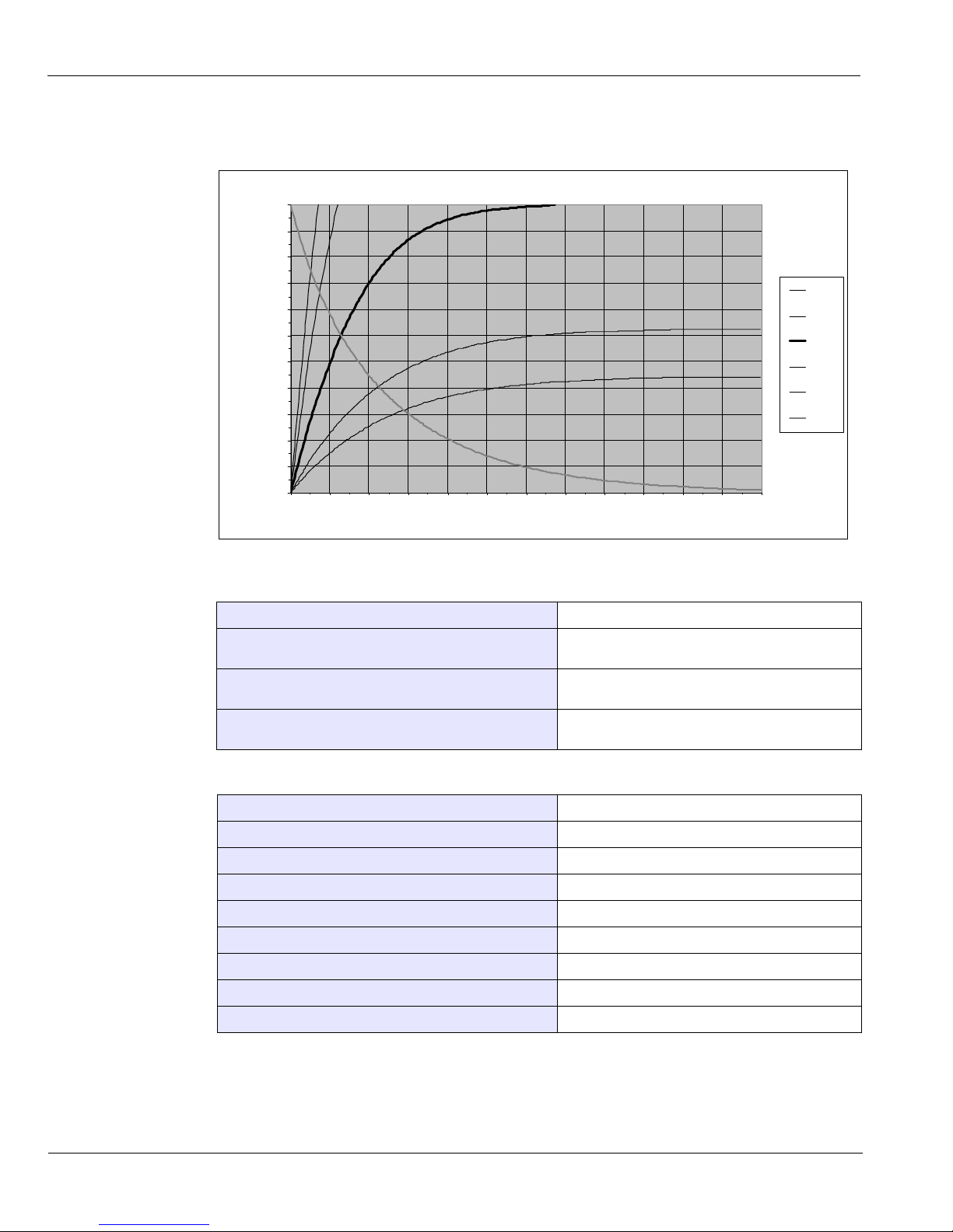
Figure 7–1 Heating and Cooling Curves of the X-ray Generator.
Table 7–4 Beam Limitations of the X-ray Generator
Manufacturer Trophy
Type Rigidly mounted unit with fixed window dimensions,
not removable, and integrated x-ray generator
Maximum symmetrical field of radiation at a distance of
613 mm from the focal point (Panoramic mode)
4 (-0.5/+1) x 128 (± 2) mm
Maximum symmetrical field of radiation at a distance of
690 mm from the focal point (3D mode)
47 (± 1) x 59 (± 1) mm
Table 7–5 Characteristics of the X-ray Tube
Manufacturer’s n ame CEI
Type OPX 105
Nominal high voltage 90 kV
Nominal anode power 810 W
Maximum amount of heat accumulated in the anode 30 kJ
Nominal focal spot diameter (IEC 60336) 0.5 mm (0.020'')
Anode materials Tungsten
Target angle 5°
Inherent filtration 0.5 mm (0.20 ") eq. Al
Heating and cooling curv es
-
10,0
20,0
30,0
40,0
50,0
60,0
70,0
80,0
90,0
100,0
110,0
0 60 120 180 240 300 360 420 480 540 600 660 720
Time in m in utes
Accumu late d h eat in kJ
100 W
66 W
33 W
15 W
10 W
Cooling
Page 61
X-Ray Generator Technical Specifications
KODAK 9000 3D Extraoral Imaging System_User Guide (SM710)_Ed 01 7–7
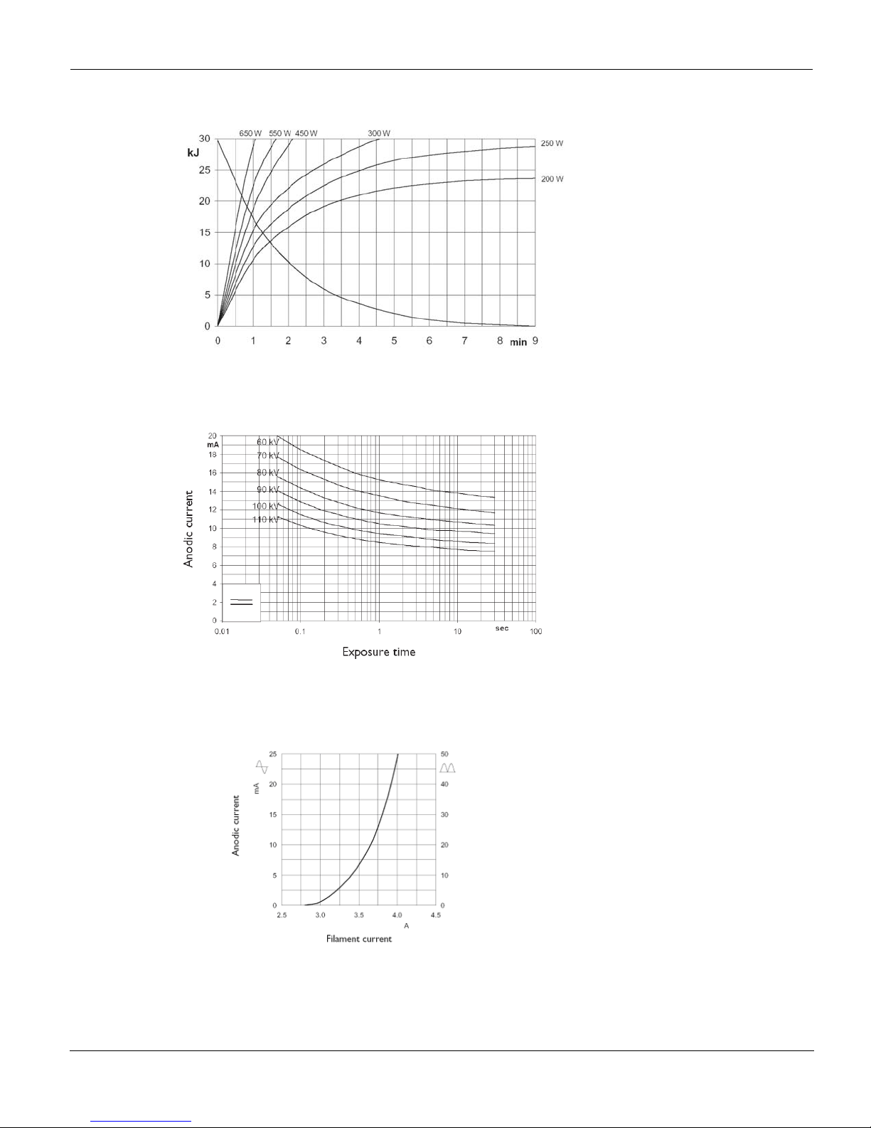
Figure 7–2 Heating and Cooling Curves of the X-ray Tube
Figure 7–3 Single Load Chart of the X-ray Tube
Figure 7–4 Filament Emissions of the X-ray Tube
Page 62

X-Ray Generator Technical Specifications
7–8 TECHNICAL SPECIFICATIONS
 Loading...