

Page 1
Page 2

Safety
• Place the Kodak Scan Station 700/720EX on a level work surface capable of supporting 9.97 kg (22 lbs.)
• When placing the Scan Station, make sure that the electrical power outlet is located within 1.52 metres (5 feet) of the Scan
Station and is easily accessible.
• When relocating the Scan Station, it is recommended that two people lift the Scan Station and use safe lifting techniques.
• Do not install the Scan Station in a location subject to dust, humidity or steam. This may cause electrical shock or a fire. Only
use the Scan Station indoors in a dry location.
• When disconnecting equipment from the electric socket, be sure to grasp the plug, not the cord.
• Never disassemble or modify the AC adapter, as this is dangerous.
• Do not use an AC adapter other than the one provided with the Scan Station. Do not use the AC adapter provided with the
Scan Station for any other products.
• Be sure the power cord is securely plugged into the wall outlet. Failure to do so may cause electrical shock or fire.
• Do not damage, knot, cut or modify the power cord or use a damaged power cord. This may cause electrical shock or fire.
• The Scan Station requires a dedicated and properly grounded power outlet. Do not use an extension cord or power strip with
the Scan Station.
• Leave sufficient space around the power outlet so it can be easily unplugged in case of an emergency.
• Do not use the Scan Station if it becomes inordinately hot, has a strange odor, emits smoke, or makes unfamiliar noises.
Immediately stop the Scan Station and disconnect the power cord from the power outlet. Contact Kodak Service.
• Do not disassemble, service or modify the Scan Station except as explained in the Administrator’s Guide.
• Do not move the Scan Station with the power cord and interface cable attached. This may cause damage to the cord/cable.
Remove the power cord from the wall outlet before moving or relocating the Scan Station.
• Follow the Kodak recommended cleaning procedures. Do not use air, liquid or gas spray cleaners. These cleaners displace
dust, dirt and debris to other locations within the scanner, which may cause the Scan Station to malfunction.
• Material Safety Data Sheets (MSDS) for chemical products are available on the Kodak website at: www.kodakalaris.com/go/
msds. When accessing the MSDSs from the website, you will be required to provide the catalog number of the consumable
you want the Material Safety Data Sheet for.
Environmental information
•The Kodak Scan Station 700/720EX is designed to meet worldwide environmental requirements.
• Guidelines are available for the disposal of consumable items that are replaced during maintenance or service; follow local
regulations or contact Kodak locally for more information.
• For recycling or reuse information, contact your local authorities, or in the USA, visit: www.kodakalaris.com/go/
scannerrecycling.
• The product packaging is recyclable.
• Parts are designed for reuse or recycling.
European Union
This symbol indicates that when the last user wishes to discard this product, it must be sent to appropriate facilities
for recovery and recycling. Please contact your local Kodak representative or refer to www.kodakalaris.com/go/
recycle for additional information on the collection and recovery programs available for this product.
Please consult www.kodakalaris.com/go/REACH for information about the presence of substances included on the
candidate list according to article 59(1) of Regulation (EC) No. 1907/2006 (REACH).
Battery Information
This product contains a Lithium Ion button cell battery. This battery can only be removed or replaced by a qualified Service
Engineer.
CAUTION:
• Risk of explosion if the battery is replaced by an incorrect type.
• Dispose of used batteries according to the instructions.
Page 3

Acoustic emission
Maschinenlärminformationsverordnung – 3, GSGV
Der arbeitsplatzbezogene Emissionswert beträgt <70 db(A).
[Machine Noise Information Ordinance — 3, GSGV
The operator-position noise emission value is <70 dB(A).]
phase est de 230 V.
EMC statements
United States: This equipment has been tested and found to comply with the limits for a Class B digital device pursuant to Part
15 of the FCC rules. These limits are designed to provide reasonable protection against harmful interference in a residential
installation. This equipment generates, uses, and can radiate radio frequency energy and, if not installed and used in
accordance with the instruction manual, may cause harmful interference to radio communications. However, there is no
guarantee that interference will not occur in a particular installation. If this equipment does cause harmful interference to radio or
television reception, which can be determined by turning the equipment off and on, the user is encouraged to try to correct the
interference by one or more of these measures:
• Reorient or relocate the receiving antenna.
• Increase the separation between the equipment and receiver.
• Connect the equipment into an outlet on a circuit different from that to which the receiver is connected.
• Consult the dealer or an experienced radio/TV technician for additional suggestions.
Any changes or modifications not expressly approved by the party responsible for compliance could void the user’s authority to
operate the equipment. Where shielded interface cables have been provided with the product or specified additional
components or accessories elsewhere defined to be used with the installation of the product, they must be used in order to
ensure compliance with FCC regulation.
Korea: As this equipment has obtained EMC registration for household use, it can be used in an area including residential
areas.
Japan: This is a Class B product based on the standard of the Voluntary Control Council for interference by information
Technology Equipment (VCCI). If this is used near a radio or television receiver in a domestic environment, it may cause radio
interference. Install and use the equipment according to the instruction manual.
Page 4

CONTENTS
OVERVIEW 1-1
PRE-INSTALLATION CHECKLIST 2-1
INSTALLATION AND GETTING STARTED 3-1
CONFIGURING DEVICE SETTINGS 4-1
DEFINING SCAN SETTINGS 5-1
CREATING DESTINATIONS 6-1
ADDING AND MANAGING GROUPS 7-1
CREATING JOBS 8-1
MONITORING AND MANAGING YOUR SCAN STATIONS 9-1
MAINTENANCE 10-1
TROUBLESHOOTING 11-1
GLOSSARY 12-1
APPENDICES
Specifications
Network Protocol
A-C
Warranty
Page 5

1 Overview
Contents What’s in the box ............................................................................1-1
Setting up the Scan Station.............................................................1-2
Setting up configurations ................................................................1-3
Scan Station components...............................................................1-5
The Kodak Scan Station 700/720EX is designed as a walk-up device
that requires no host PC or application sof tware. I t works with a nd uses
an existing network and network shared services to communicate with
other network devices or destinations. The Scan S t ation 700/720EX is a
capture solution that allows you to quickly send your documents via
email, network, networked printers, USB drives, FTP, SharePoint and
Kofax Front Office Server with a simple touch.
This Administrator’s Guide provides the information you need to setup
and administer the Kodak Scan Station 700 and Kodak Scan Station
720EX. For the purpose of this manual both models will be referred to
as Kodak Scan S t ation 700. An y dif ference s between these models will
be noted.
What’s in the box Before you begin open the box and check the contents:
• Kodak Scan Station 700/720EX
• Power cord bundle
• Welcome Folio which includes:
- Installation CD
- Registration sheets
- User Reference Guide, English
- Maintenance Reference Guide, English
- Installation Guide
- Country Contact sheet
- Miscellaneous flyers
A-61796 December 2013 1-1
Page 6

Setting up the Scan Station
Carefully unpack the Scan Station 700 and place it on a clean, dry and
level surface. Refer to the Installation Guide or the “Rear view”
illustration later in this chapter for port locations.
1. Select the appropriate AC power cord. Plug the power adapter into
the power port on the Scan Station. Plug one end of the p ower cord
into the power adapter and plug the other end into the wall outlet.
2. Plug one end of the 10/100/1000 Base T network cable (customer
provided) into the Ethernet port of the Scan Station and plug the
other end of the network cable into the network port.
3. If you have a Scan Station 720EX, connect a phone line to the
RJ-11 modem port.
4. When the Scan Station is properly connected, press the power
button and wait a few moments for the Scan Station to start up and
display the application.
5. Proceed to Chapter 2, Pre-installation Checklist to review and
gather the necessary configuration information before installing the
Kodak Scan Station 700/720EX - Scanner Administration
application and creating configurations.
6. After reviewing the Pre-installation Checklist, you can setup your
configurations. See Chapters 3-8 for more information.
1-2 A-61796 December 2013
Page 7

Setting up configurations
You must configure the Scan Station using the Kodak Scan Station 700/
720EX - Scanner Administration application before you can use it. The
application allows you to configure and manage your Scan Stations.
A Scan Station configuration consists of setting the following groups of
options: Device Settings, Scan Settings, Destinations, Groups, and
Jobs. These options are accessible via the Configuration tab on the
Scan St ation 700/720EX - Scanner Administration application using the
Edit menu.
• Device Settings — consists of the following configuration items. See
Chapter 4 for more information.
- De vice Options: used to configure the Scan S t ation (e.g., display
language, date, time, etc.).
- Email Server: used to configure the Scan Station to use an
SMTP server. Configuration of an email server is required if you
will be sending documents to an email destination.
- Active Directory Server: used to configure the location of an
Active Directory Server. Th is will be required if you want to define
users and groups of users from your Active Directory Server.
- Fax: used to configure fax options. Fax configuration will be
required if you will be sending scanned documents via fax.
• Scan Settings — allows you to define items that determine how a
document will be scanned (e.g., black and white, two sided, 300 dpi,
etc.), the output format (e.g., PDF, JPEG, XLS, etc.), any special
processing, and how to name the scanned document. Multiple scan
settings can be configured. For example, you can setup a scan
setting configuration for scanning color documents, an d another scan
setting configuration for scanning black and white documents. After
defining your scan setting configuration, you will be prompted to
name your configurations for later use. See Chapter 5 for more
information.
• Destinations — allows you to define where the scanned image(s) is
sent or stored. The Scan Station can send or store documents to
email, a network folder, printer, FTP, fax, email to fax, SharePoint,
and Kofax Front Office Server. For example, you could define a
destination named Invoices that sends scanned documents to
SharePoint and a printer; and define another destination named
Purchase Orders that only sends scanned documents to SharePoint.
After defining your destinations, you will be prompted to name your
destinations for later use. See Chapter 6 for more information.
• Groups — groups are used to control access to jobs for specific
users or groups of users. See Chapter 7 for more information.
• Jobs — jobs are a combination of Scan Settings, Destinations and
Groups. A job is represented on the Scan Station user interface as a
single button, such as Invoices. A job allows one touch scanning
since a job will define how a document should be scanned and
formatted (Scan Settings), where the document should be stored or
sent (Destinations), and the users or groups of users that are allowed
to use a particular job (Groups). See Chapter 8 for more information.
A-61796 December 2013 1-3
Page 8

It is suggested that scan settings, destinations and groups be defined
before defining any jobs. Each Scan Setting, Destination and Group
configuration will have an associated name that will be used when
defining a job.
The Scan Station can be configured to force a user to login. The login
information is matched with the groups defined for each job. When a
user logs into the Scan Station, the only buttons that will be displayed
are jobs that the user has access to.
1-4 A-61796 December 2013
Page 9

Scan Station
1
2
3
9
4
5
6
7
8
components
Front view
1 Input tray extender — pull this extender out to accommodate document
sizes over 8 1/2 x 11 inches (A4).
2
Input tray — holds up to 75 sheets of 80 g/m
3 Side guides — slide the guides back a nd forth to accommod ate the width
of the documents you want to scan.
4 Touch screen — allows you to easily select a job or navigate through
optional selections with a simple touch. The touchscreen is the primary
user interface for interacting with the Scan Station.
2
(20 lb.) paper.
5 Output tray panel — covers the transport when not in use. This panel
must be open to scan documents. When opened, collects the scanned
documents. The Scan Station cover cannot be opened when the output
tray panel is closed.
6 Output tray extender — pull this extender out when scanning document s
longer than 11 inches (28 cm).
7 Microphone — used for creating voice annotation.
8Power — turns the power on and off. See the section entitled, “Indicator
lights” in Chapter 9 for more information.
9 Scan Station cover release lever (not visible in illustration) — provides
access to the internal components for maintenance and clearing jams.
A-61796 December 2013 1-5
Page 10

Inside view
1
2
3
4
5
6
7
8
1 Separation module release lever/separation module — push the
release lever down to remove the separation module for cleaning or
replacement. The separation module provides smooth document feeding
and separation of various sizes, thicknesses and textures of documents.
2 Gap release lever — allows you to manually adjust the space between
the feed module and separation module for documents that require special
handling.
3 Scan Station cover release lever — opens the Scan Station to allow
access to the paper path for cleaning or clearing a docu ment jam.
4 Feed module — provides smooth document feeding and separation of
various sizes, thicknesses and textures of documents.
5 Paper present sensor — detects the presence of documents in the input
tray.
6 Feed module cover — this cover needs to be removed when cleaning or
replacing the feed module or feed module tires.
7 Imaging guides — for optimum image quality, keep the upper and lower
imaging guides clean.
8 Multifeed detection sensor — detects if more than one documen t enters
the paper path at a time.
.
1-6 A-61796 December 2013
Page 11

Rear view
1
2
3
4
5
1 Modem port — the RJ-11 port connects the fax modem to a phone line.
This is only for the Scan Station 720EX.
2 Security lock port — connects a security lock to the Scan Station. You
can purchase a standard security lock at an office supply store. Refer to
the instructions provided with the security lock for installation procedures.
3 Power port — connects the power cord/adapter to the Scan Station.
4 USB ports — connects peripheral devices (e.g., keyboard, mouse and
other accessories) to the Scan Station.
5 Ethernet port — connects the Scan Station to the network.
A-61796 December 2013 1-7
Page 12

2 Pre-installation Checklist
Contents Network configuration details..........................................................2-1
Best practices .................................................................................2-1
Pre-installation checklist .................................................................2-2
Network configuration details
Because the Scan Station is a network device, a basic knowledge of
networking principles and terminology is helpful. You should be familiar
with the concept of creating user accounts (on domains), sharing
folders, setting access privileges, the Universal Naming Convention
(UNC), using IP addresses, fully qualified domain names (FQDNs) and
creating user groups.
NOTE: Some of the concepts covered in this section assume
knowledge of Microsoft NT Domains and permissions. Refer to
your documentation for Microsoft Windows Server 2003, 2008
or 2012 for more information.
Best practices Scan Station user groups — for network domain environments, you
should create a user group for all Scan Stations. This group will be
used to hold account names that are assigned to each Scan Station.
Minimally, there should be one account name that is assigned to each
Scan Station. Optimally, each Scan Station should be assigned its own
unique username and password and these accounts should be
contained within a group that is reserved specifically for Scan Stations.
These account names will be used when configuring the Scan S tation’ s
network settings and entered into the Username, Password, and
Network Domain fields.
NOTE: The Scan Station groups and login names must be given
appropriate privileges to access the network resources that the
user will see as Destination selections at the Scan Station.
Workgroup environments — for network environments that use the
Microsoft “Workgroup” configuration, you may be required to create an
account name and password to be assigned to Scan Stations. These
account names will be used when configuring the Scan Station’s
network settings and entered into the Username and Password fields.
The Network Domain field should be left blank in Workgroup
environments.
Network folders — it is recommended that you create network folders,
for either Destination or Remote Configuration, that can be accessed
(minimally read, write, change access) by any Scan Station login
account or by the user group created for Scan Stations.
A-61796 December 2013 2-1
Page 13
UNC names for folders — you will need to know the fully qualified
UNC name for each network folder that will be used by your Scan
Station(s). When configuring network destinations, this will be the
information entered into the Address field of the Add: Network Folder
dialog box. For example, you could create a folder called “scanfolder”
on a server called “acmeserver” that would be reserved for Scan
Station access. You would reference it by the following UNC name:
\\acmeserver\scanfolder.
NETBIOS usage — in network environments that use routers it is
common practice to block NETBIOS traffic on your router. You may
need to know the IP address of the server where you want to scan
documents. By substituting the IP address of the server instead of the
NETBIOS computer name, you can bypass the network traffic
restrictions that may cause network scanning to fail. For example, the
previously defined network address: \\acmeserver\scanfolder should be
replaced with something similar to: \\192.168.2.10\scanfolder.
Pre-installation checklist
It is recommended that you review this checklist before configuring the
Kodak Scan St ation 700. This information is needed to creat e the initial
configuration file to complete the installation. Locate any information
you are unsure of before creating the configuration file. See your
system or network administrator if you have questions about this
information.
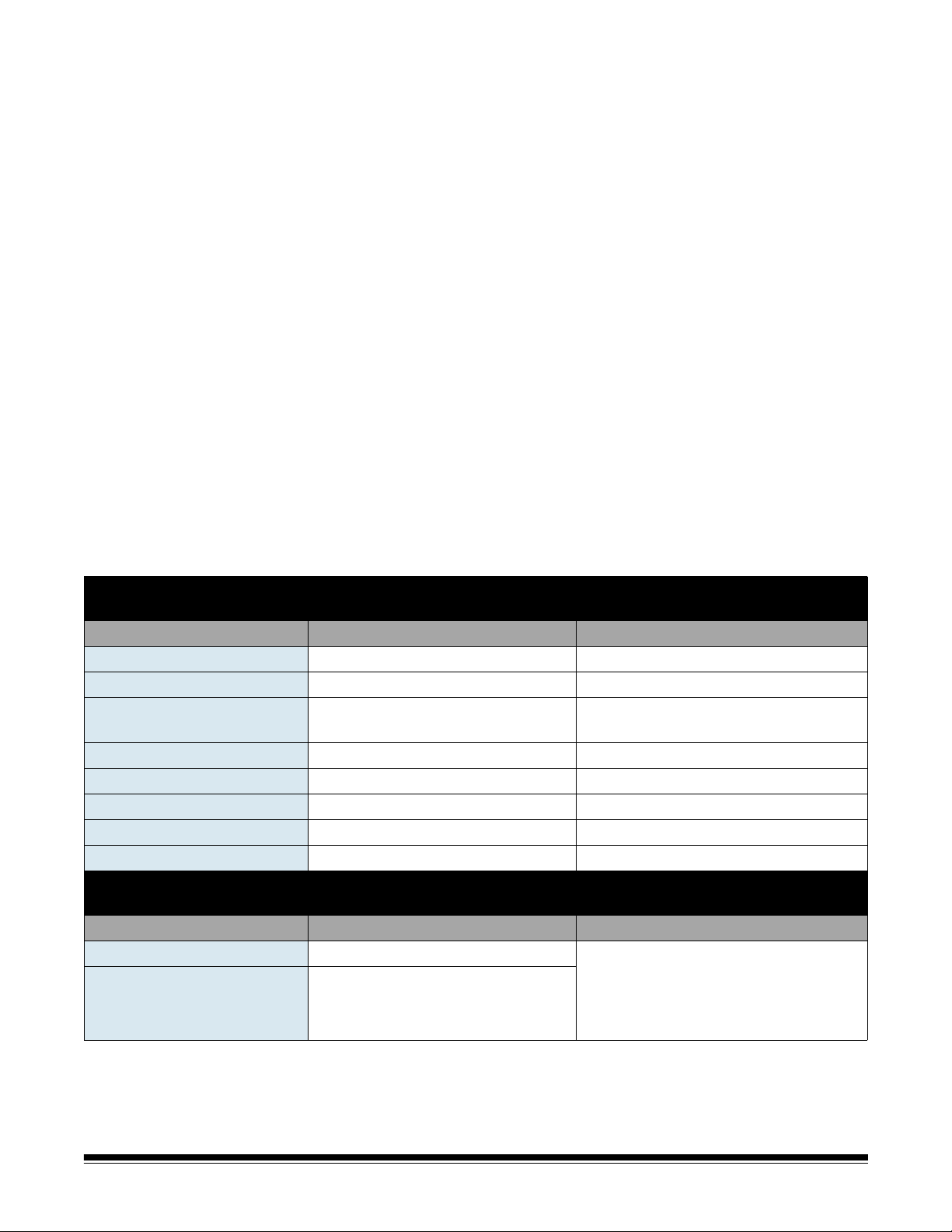
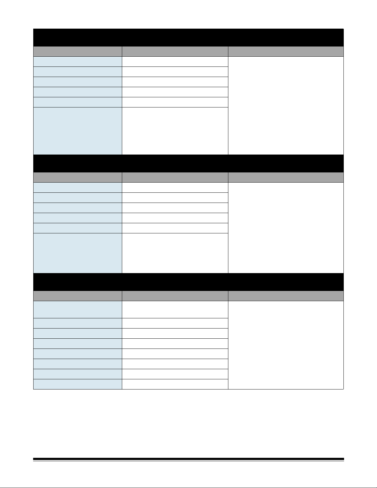
Device Settings/IP Address
The following settings are found using the Scanner tab and by selecting Scanner>Add.
Parameter Name Your Setting Chapter Reference
Automatic (DHCP) See Chapter 9, “Adding a Scanner”.
IP Address Settings — Static
Static (IPv4)
IP Address
Subnet Mask
Default Gateway
Preferred DNS Server
Alternate DNS Server
Preferred WINS Server
Device Settings/Network Destination Credentials
The following settings are found using the Configuration tab and by selecting Edit>Device Settings.
Parameter Name Your Setting Chapter Reference
Username, Password, Domain • See Chapter 9, “Best practices” for
Remote Configuration Settings
creating an account for your Scan
Station.
• See Chapter 4, “Configuring your
device options”.
2-2 A-61796 December 2013
Page 14
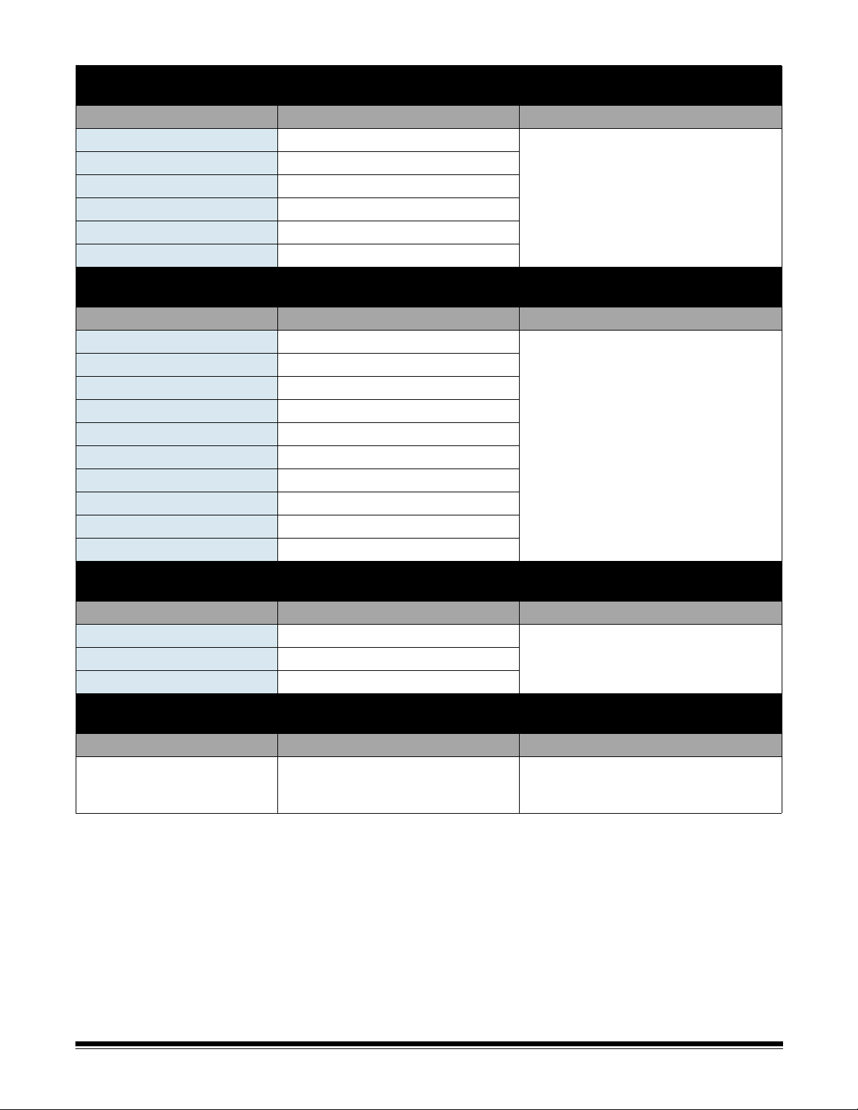
Device Settings/Email (SMTP) Server
The following settings are found using the Configuration tab and by selecting Edit>Device Settings.
Parameter Name Your Setting Chapter Reference
Email Server Address
Username, Password, Domain
Port
Authentication Scheme
Maximum Attachment Size
Security Type
Device Settings/Active Directory Server
The following settings are found using the Configuration tab and by selecting Edit>Device Settings.
Parameter Name Your Setting Chapter Reference
Server Address
Username, Password, Domain
Port
Base DN
Search Field Tag
Email Address Tag
Full Name Field Tag
Home Directory Tag
Fax Field Tag
Security Type
Device Settings/Fax
The following settings are found using the Configuration tab and by selecting Edit>Device Settings.
Parameter Name Your Setting Chapter Reference
Outside Line Prefix
Modem Country Code
LAN Fax Server Domain Name
Network Destination
The following settings are found using the Configuration tab and by selecting Edit>Destinations.
Parameter Name Your Setting Chapter Reference
Complete directory path (the
folder where you will put the
scanned documents).
See Chapter 4, “Configuring email
settings”.
See Chapter 4, “Active Directory Server
settings”.
See Chapter 4, “Fax settings”.
Chapter 6, “Setting up a network
destination”.
A-61796 December 2013 2-3
Page 15
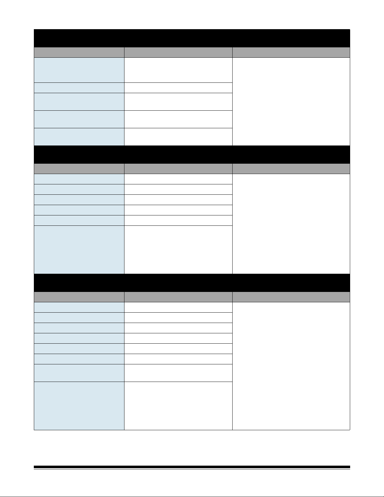
The following settings are found using the Configuration tab and by selecting Edit>Destinations.
Parameter Name Your Setting Chapter Reference
Complete directory path (the
directory path to the printer
server queue)
Username, Password, Domain
Address (for direct connection
to a printer)
Driver name (for direct
connection to a printer)
Port name (for direct
connection to a printer)
The following settings are found using the Configuration tab and by selecting Edit>Destinations.
Parameter Name Your Setting Chapter Reference
Address
Username, Password
Protocol (FTP)
Port number
Passive (Enable/Disable)
Proxy
•Proxy Type
• Proxy Address
•Username
• Password
• Port Number
The following settings are found using the Configuration tab and by selecting Edit>Destinations.
Parameter Name Your Setting Chapter Reference
Address
Username, Password
Protocol (FTPS)
Port number
Encryption
Passive (Enable/Disable)
SSL Server Certificate (Enable/
Disable)
Proxy
•Proxy Type
• Proxy Address
•Username
• Password
• Port Number
Printer Destination
Chapter 6, “Setting up a printer
destination”.
FTP Destination
Chapter 6, “Setting up a FTP site”.
FTPS Destination
Chapter 6, “Setting up a FTP site”.
2-4 A-61796 December 2013
Page 16
The following settings are found using the Configuration tab and by selecting Edit>Destinations.
Parameter Name Your Setting Chapter Reference
Address
Username, Password
Protocol (SFTP)
Port number
Private Key File, Password
Proxy
•Proxy Type
• Proxy Address
•Username
• Password
• Port Number
The following settings are found using the Configuration tab and by selecting Edit>Destinations.
Parameter Name Your Setting Chapter Reference
SharePoint website URL
Username, Password
Document Path
Index Fields
Certificate, Password
Proxy
• Proxy Address
•Username
• Password
• Port Number
The following settings are found using the Configuration tab and by selecting Edit>Destinations.
Parameter Name Your Setting Chapter Reference
Kofax Front Office Server
address
Port number
Username, Password
Client ID
Shortcut Type
Shortcut Name
Index Fields
Certificate, Password
SFTP Destination
Chapter 6, “Setting up a FTP site”.
SharePoint Destination
Chapter 6, “Adding a SharePoint group”.
Kofax Front Office Server Destination
Chapter 6, “Adding a Kofax Front Office
Server group”.
A-61796 December 2013 2-5
Page 17

3 Installation and Getting Started
Contents Setup overview ...............................................................................3-1
Installing the Kodak Scan Station 700/720EX - Scanner
Administration application.............................................................3-2
The main screen.............................................................................3-3
Menus.............................................................................................3-5
File menu....................................................................................3-5
Edit menu....................................................................................3-6
Scanner menu.............................................................................3-6
Help menu...................................................................................3-9
Icons ...............................................................................................3-9
Setup overview Following is a list of things you need to do to prepare for configuring
your Scan Station 700.
• Unpack your Scan Station(s) according to the unpacking instructions
in the box that your Scan Station was packaged in.
• Setup the Scan Station and make the necessary connections. See
the Installation Guide or the section entitled, “Setting up the Scan
Station” in Chapter 1.
• Review the pre-installation checklist in Chapter 2 and gather all of the
information required to configure the Scan Station. Having this
information available in advance will help ensure an easy Scan
St a tion configuration.
• Install the Kodak Scan Station 700/720EX - Scanner Administration
application on a separate PC. See the section entitled, “Inst alling the
Kodak Scan Station 700/72 0EX - Scanner Administration application”
later in this chapter for procedures.
A-61796 December 2013 3-1
Page 18

Installing the
Kodak Scan Station
700/720EX
- Scanner
Administration
application
You must install the Kodak Scan Station 700/720EX - Scanner
Administration application on a host PC. The Kodak Scan Station 700/
720EX - Scanner Administration application allows you to properly
setup, configure and manage Scan Station 700/720EX/500/520EX
devices over a network in an efficient and productive manner. This
application communicates with Kodak Scan Station 500 and 700
devices over the network; thereby minimizing the need for individual
access to multiple Scan Stations.
1. Insert the Installation CD titled, “Scanner Administration and
Supporting Documentation” in the CD-ROM drive on the computer
where the Kodak Scan Station 700/72 0EX - Scanner Administration
application will be installed. The installation software starts up
automatically.
NOTE: If .NET Framework 4.0 is not already installed, the Kodak
Scan Station 700/720EX - Scanner Administration
application installer will install them before installing the
Kodak Scan Station 700/720EX - Scanner Administration
application.
2. Click Next when the Kodak Scan Station 700 splash screen is
displayed.
3. Click Next when the Welcome screen is displayed.
4. Click I Agree after you have read and agreed with the terms of the
Software License Agreement, then click Next.
The Ready to Install Program screen will be displayed.
5. Click Install to continue.
6. After the Kodak Scan Station 700/720EX - Scanner Administration
application has been installed, click Finish.
7. Remove the Installation CD from the CD-ROM drive.
8. After installing and running the application, the Kodak Scan Station
700/720EX - Scanner Administration main screen will be displayed.
3-2 A-61796 December 2013
Page 19

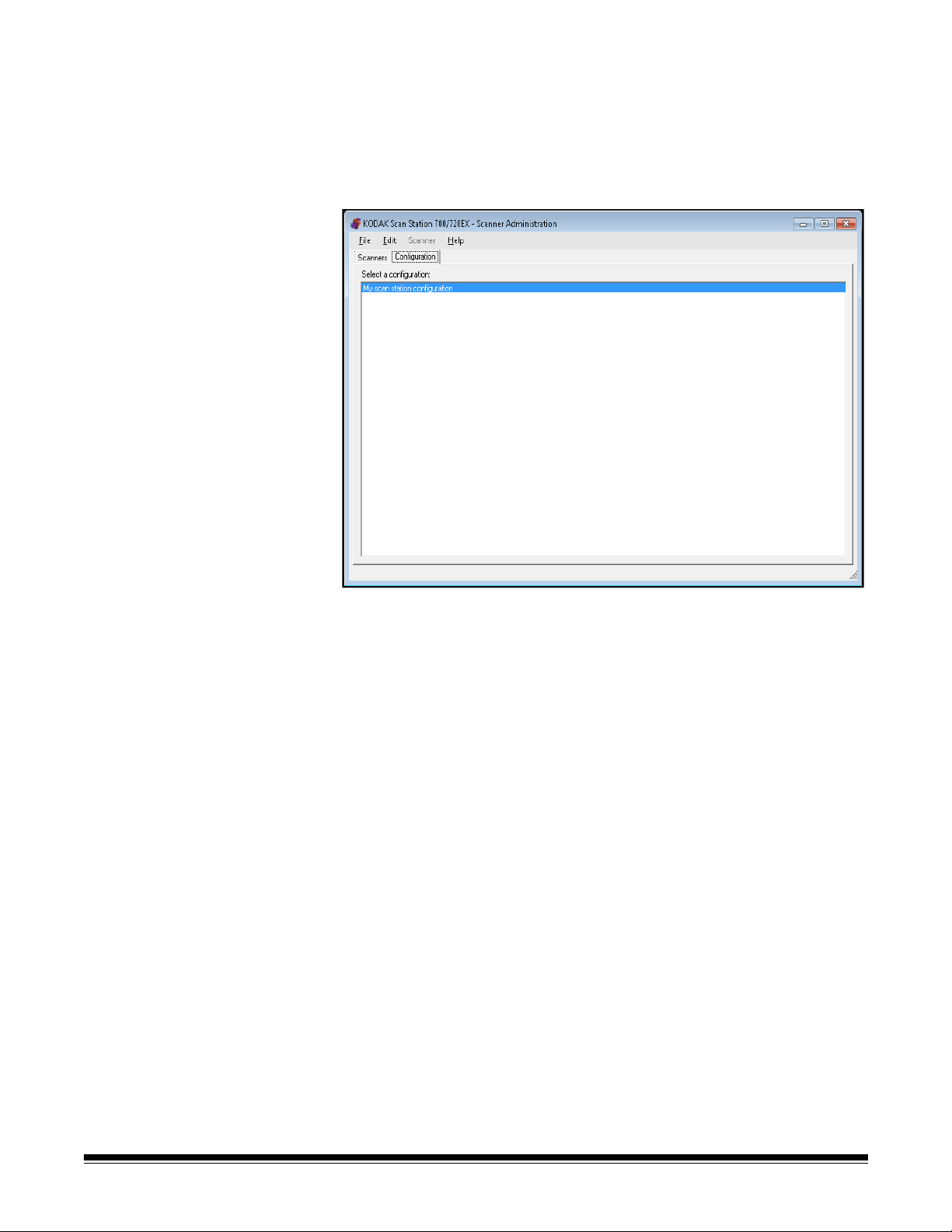
The main screen The main screen provides two tabs:
• Scanners tab — allows you to monitor any Scan Stations that have
been discovered and configured. See Chapter 9, Monitoring and
Managing Your Scan Stations for more information.
NOTE:In addition to the Scan Station 700/720EX, the Kodak Scan
Station 500/520EX can be managed from the Scanner tab
and the Scanner menu.
• Configuration tab — allows you to configure and set up your Scan
Stations. After you have created at least one configuration, this
screen will be displayed with a list of your previously created
configurations.
NOTE:The Configuration tab and the File and Edit menus only apply
to the Scan Station 700/720EX.
The Scan Station 500/520EX must be configured using the
Kodak Scan Station Configuration Organizer. See your
Administrator’s Guide for the Kodak 500/520EX for more
information.
A-61796 December 2013 3-3
Page 20
A configuration is a collection of Device settings, Scan settings,
Destinations, Groups, and Job settings. Configurations are stored
on your PC in a configuration database and maintained by the
Kodak Scan Station 700/720EX - Scanner Administration
application. Detailed procedures for configuring these settings are
described in Chapters 4-8.
3-4 A-61796 December 2013
Page 21
Menus The File, Edit, Scanner and Help menus are available from the Kodak
Scan Station 700/720EX - Scanner Administration main screen.
NOTE: When the Configuration tab is selected, only the File, Edit and
Help menus are available.
When the Scanners tab is selected, only the Scanner and Help
menus are available.
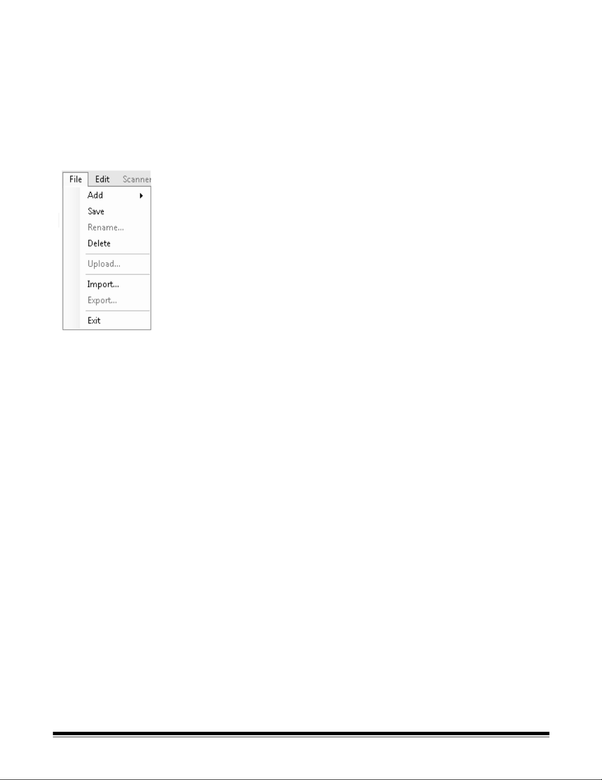
File menu Following is a description of the menu options on the File menu.
Add — allows you to create a new configuration from the default or
from an existing configuration.
• From default configuration: when selected, displays the Device
Settings screen. For more information see Chapter 4, Device
Settings.
• From selected configuration: when selected, displays the
Configuration Name screen which allows you to name a new
configuration which is based on the currently selected configuration.
If you want to base a new configuration on an existing one (not the
default), select the base configuration, then select File>Add>From
the selected configuration. If there are no configurations (other
than the default), this option is grayed out.
Save — saves the selected configuration to the configuration dat abase
located on the PC running the Kodak Scan Station 700/720EX Scanner Administration application.
Rename — displays the Configuration Name screen allowing you to
rename the selected configuration.
Delete — deletes the selected configuration.
Upload — allows you to send the selected configuration to the Scan
Station. This option is grayed out if no Scan Stations are accessible by
the Kodak Scan Station 700/720EX - Scanner Administration
application.
Import — allows you to import a configuration file from any location to
the Kodak Scan Station 700/720EX - Scanner Administration
application.
Export — allows you to export a configuration file from the Kodak Scan
St ation 700/720EX - Scanner Administration application to any locatio n.
Exit — closes the Kodak Scan Station 700/720EX - Scanner
Administration application.
A-61796 December 2013 3-5
Page 22

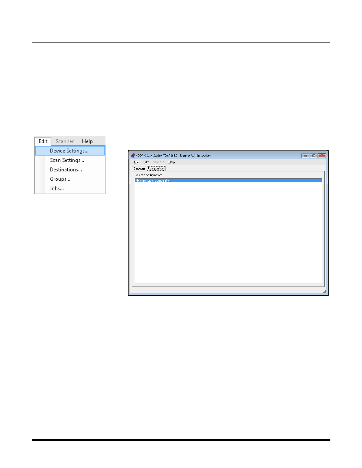
Edit menu Following is a description of the menu options on the Edit menu.
Device Settings — allows you to configure the parameters that the
Scan Station needs to send emails, communicate with an Active
Directory Server for security purposes and set Scan Station defaults.
For more information, see Chapter 4, Device Settings.
Scan Settings — allows you to set basic image processing settings,
such as, color/grayscale/black and white, output file format,
compression, and some advanced options like Hole Fill, Streak Filter,
etc. For more information, see Chapter 5, Scan Settings.
Destinations — allows you to add or modify destinations (e.g., email,
network folder, printer, FTP site, etc.) that define where the scanned
output will be sent. For more information, see Chapter 6, Creating
Destinations.
Groups — allows you to create or modify a group of users from an
Active Directory Server. Other users that are not in an Active Directory
Server group can also be added. For more information, see Chapter 7,
Adding and Managing Groups.
Jobs — allows you to create or modify jobs which are a collection of
scan settings, destinations and groups of users. For more information,
see Chapter 8, Creating Jobs.
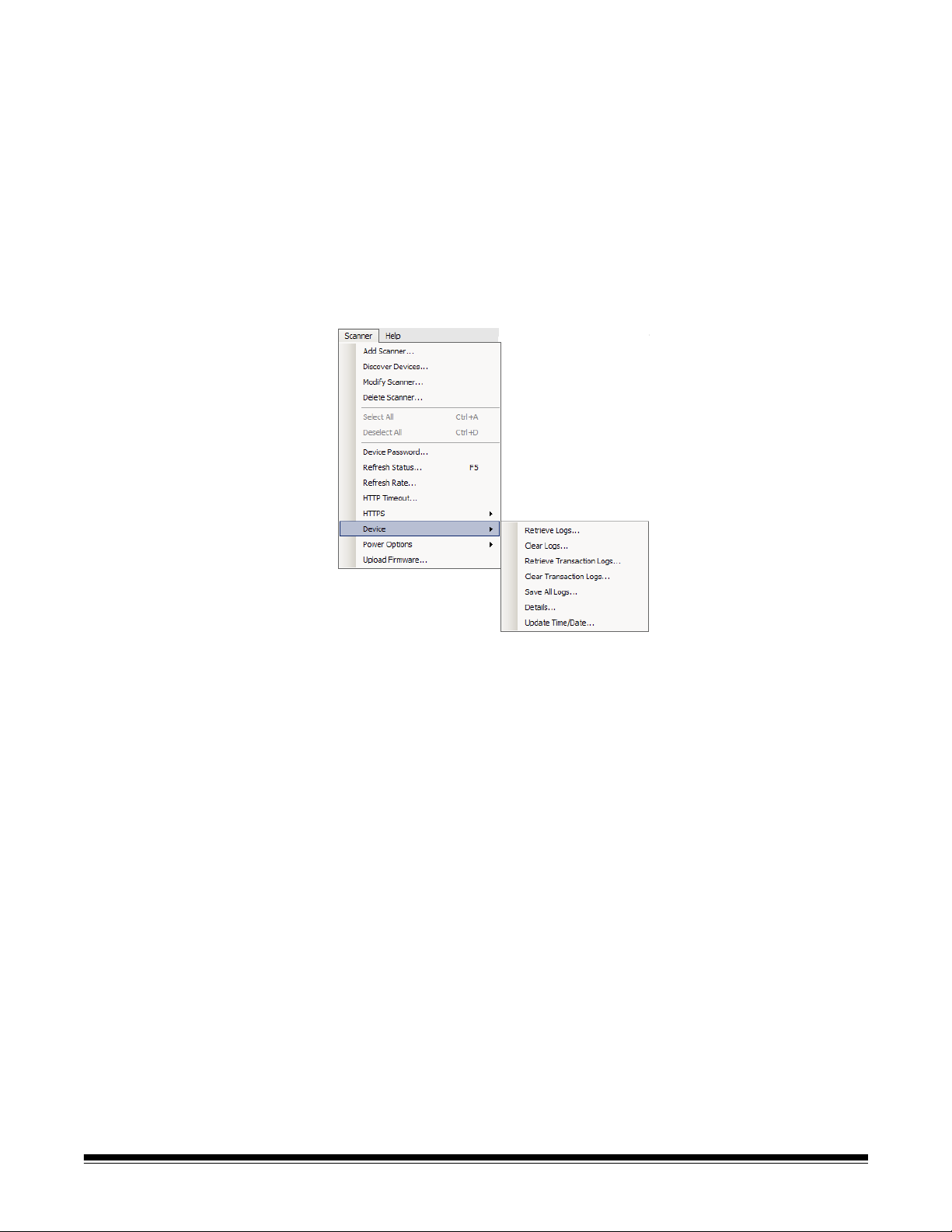
Scanner menu Following is a description of the menu options on the Scanner menu.
Refer to Chapter 9, Monitoring and Managing Your Scan Stations for
more information and procedures regarding these options.
Add Scanner — displays the Add Scanner dialog box, which allows
you to register Scan Stations that you want to manage remotely.
Discover Devices — allows you to scan a range of IP addresses and
automatically register any Scan Station within that range that responds
to the request.
NOTE: Any Scan Station that has previously had its device password
changed will not respond to the discovery request. If this is the
case, you will need to select Scanner>Add Scanner and enter
the Scan Station’s password in the Device Password field.
Modify Scanner — allows you to rename the selected Scan Station
and configure network settings.
Delete Scanner — deletes the selected Scan St ation(s) from the list of
administered Scan Stations.
Select All — allows you to select all the Scan Stations that are
displayed in the list; you can also press Ctrl+A to select all Scan
Stations.
Deselect All — allows you to deselect all the Scan Stations that are
currently selected; you can also press Ctrl+D to deselect all Scan
Stations.
3-6 A-61796 December 2013
Page 23

Device Password — displays the Device Password dialog box which
allows you to change the network connection password to the Scan
Station.
NOTE: This device password is used by the Kodak Scan Station 700/
720EX - Scanner Administration to communicate with the Scan
Station.
Refresh Status — displays the current state of the selected Scan
Station(s):
• Idle — the Scan Station is currently active on the network; but not in
use.
NOTE: Any user interaction using the touch screen will put the
Scan Station into the In Use state (see below).
• Scanning — Scan Station is scanning.
• Processing images — the Scan Station is processing images (e.g.,
converting images to PDF).
• Sending email — the Scan Station is sending an email.
• Saving — images are being saved to a USB drive, network folder,
FTP site, or a SharePoint site.
• Printing — the Scan Station is printing images using a remote
printer.
• Scan Completed — the Scan Station has successfully completed
the scanning session. When Done is selected on the Scan Station,
the Scan Station will go into the Idle state.
• Error — the Scan Station failed to complete the scanning session.
When Done is selected on the Scan Stati on, the Scan Station will go
into the Idle state.
• Cancelled — the scanning session has been cancelled. After the
inactivity time period has been reached, the Scan Station will go into
the Idle state.
• Preview — the Scan Station Preview feature is in use.
• Sending Fax — the Scan Station is sending a fax. This is only
displayed if the Scan Station is not currently scanning.
• Receiving Fax — the Scan Station is receiving a fax. This is only
displayed if the Scan Station is not currently scanning.
• Powering down — the Scan Station is in the process of a powerdown sequence.
• Rebooting — the Scan Station is in the process of being restarted.
• Updating — the configuration file or firmware is currently being
updated.
•In Use — when a USB flash drive is inserted, a user is logging in or is
interacting with the Scan Station, this state is displayed.
• Not found — the Scan St ation cannot be found on the network (e. g.,
power is turned off).
A-61796 December 2013 3-7
Page 24
Refresh Rate — allows you to set the amount of time that the
application will try and communicate with all Scan Stations.
HTTP Timeout — allows you to adjust the amount of time (in seconds)
that the HTTP commands have to complete. If some commands
timeout and do not complete, adjust this to a higher value.
HTTPS — turning HTTPS on will encrypt data as it is communicated
between the Kodak Scan Station 700/720EX - Scanner Administration
application and the Scan Station.
Device — provides the following options. Procedures on how to use
these functions are described in Chapter 9, Monitoring and Managing
Your Scan Stations.
• Retrieve Logs: allows you to save the log files retrieved from the
selected Scan Station.
• Clear Logs: when selected, the following message will be displayed,
Are you sure you want to clear the log files of the selected
scanner? If you click Yes, the log files will be cleared.
• Retrieve Transaction Logs: allows you to save the transaction log
file retrieved from the selected Scan Station.
• Clear Transaction Logs: when selected, the following message will
be displayed, Are you sure you want to clear the transaction log
files of the selected scanner? If you click Yes, the transaction log
files will be cleared.
• Save All Logs: saves all available log files found on the selected
Scan St ations and saves them to the selecte d directory. The logs will
be saved in the selected directory under the Device Name folder of
the Scan Station.
• Details: provides device information about the selected Scan
St ations including network configuration, sof tware versions a nd p age
count.
• Update Time/Date: allows you to set the NTP time server for all
selected Scan Stations.
3-8 A-61796 December 2013
Page 25
Power Options — provides options for restarting and turning off the
selected Scan Stations.
Upload Firmware — displays the Open dialog box which allows you to
upload new firmware updates to the Scan Station.
Help menu Following is a description of the menu options on the Help menu.
Contents — provides the on-line help for the Kodak Scan Station 700/
720EX - Scanner Administration.
Index — provides an alphanumeric listing of keywords associated with
the Kodak Scan Station 700/720EX - Scanner Administration.
About — displays the About screen for Kodak Scan S t ation 700/720EX
- Scanner Administration application, which provides information about
the current version of the software.
Icons The information in Chapters 4-8 outline a step-by-step procedure for
setting up your Scan Stations. Most screens have one or more of the
following icons.
Creates a new entity.
Edits an existing entity.
Deletes the selected entity.
Displays the current state of the Scan Station:
•Idle
• Scanning
• Processing images
• Sending email
•Saving
•Printing
• Scan Completed
•Error
• Cancelled
•Preview
• Sending Fax
• Receiving Fax
• Powering down
• Rebooting
• Updating
•In Use
• Not found
Retrieves, displays and allows the saving of the log file on the
selected Scan Station.
Displays and allows the saving of the transaction log file on the
selected Scan Station.
Displays detailed information about the selected Scan Station
(e.g., software version, IP address, etc.).
A-61796 December 2013 3-9
Page 26
4 Configuring Device Settings
Contents Device Settings...............................................................................4-1
Configuring your device options..................................................4-3
Configuring email settings...........................................................4-8
Configuring Active Directory Server settings ............................4-10
Configuring Fax settings...........................................................4-12
Email address summary........................................................4-15
Device Settings The Device Settings option allow you to configure the Scan Station for
sending emails, communicate with the Active Directory Server for
authentication purposes and set Scan Station defaults.
To set up a configuration:
1. Select the configuration that you want to apply settings to or create
a new configuration (File>Add).
A-61796 December 2013 4-1
Page 27

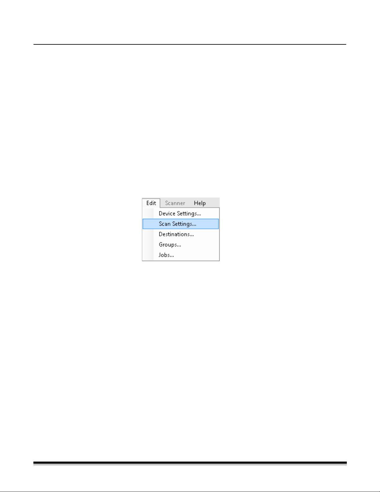
2. Select Edit>Device Settings.
Check all options that you want to configure and click Next. The
software will step you through each option.
• Device Options — allows you to set the following options:
- Language
- Device/Administrator Password
- Network Destination Credentials
- Remote Configuration Settings
- Volume
- Configuration Options
- Date and Time
- Power Saver
• Email Server — for the Scan Station to send documents to email
recipients, you must define how the Scan Station will access your
email server (e.g., SMTP, Return Email Address, etc.).
• Active Directory Server — allows you to configure your connection
to the Active Directory Server which allows the Scan Station to
authenticate credentials and look up specific user information, such
as their home directory on the network.
• Fax — allows you to configure the Scan Station to send and receive
faxes.
4-2 A-61796 December 2013
Page 28
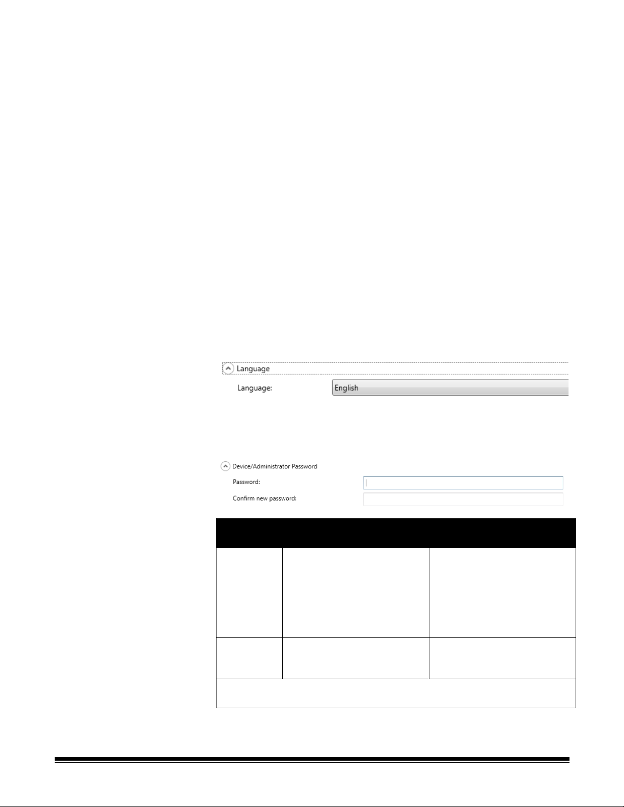
Configuring your device options
This screen allows you to setup the following device options:
Language — click the down arrow to select the language that will be
used on the Scan Station display.
Device/Administrator Password — allows you to set a password that
controls user access to the Scan Station.,
Force User
Login
On The user must login into the
Off Device password is required to
It is recommended that a device password be set to guard against a nonprivileged user from gaining access to administrator functions.
Device Password
Set
Scan Station with their user
name and password. The
device password is required to
update the Scan Station if a
user inserts a USB drive
containing a configuration file.
use the Scan Station and apply
a configuration file.
Device Password Blank
(default)
The user will login into the Scan
Station with their user name
and password. No password is
required to update the Scan
Station if a USB drive
containing a configuration file is
inserted.
No access control.
A-61796 December 2013 4-3
Page 29
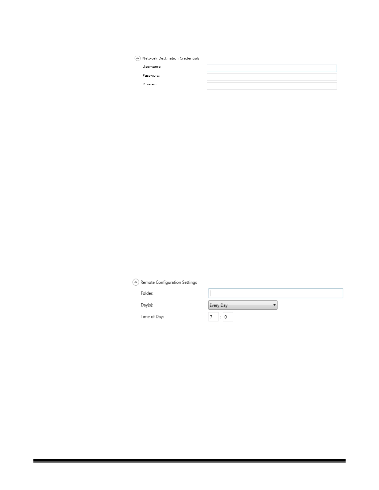
Network Destination Credentials — when selected, define the
Username, Password and Domain required to access network
resources.
1. Enter the network user name assigned to the Scan Station. For
more information see the section entitled, “Network configuration
details” in Chapter 2.
NOTE: If you want the Scan Station to have access to network
printers or network shared folders, the credentials provided
must have sufficient privileges to access these resources.
2. Enter the password for the network user name in the Password
field.
NOTE: This password is only used by the Scan Station and will
never be displayed in readable form. The password is
stored in encrypted format.
3. Enter the Microsoft network domain name which the Scan Station
will be connected to in the Domain field. In a workgroup
environment, this field can be left blank.
Remote Configuration Settings — the Scan Station can be
configured to look for an updated configuration on specific days and
times. Select this option to allow your Scan Station to auto matically look
for an updated configuration.
1. Enter a network folder where the Scan Station will find updated
configuration settings.
2. Select which day(s) of the week this operation will be performed.
3. Select the time of day you want your Scan Station to check for
updates.
NOTE: When updating a configuration using this method, the fields
on the Add Scanner/Modify Scanner dialog box will not be
updated: Device Name, IP Address and Device Password.
4-4 A-61796 December 2013
Page 30
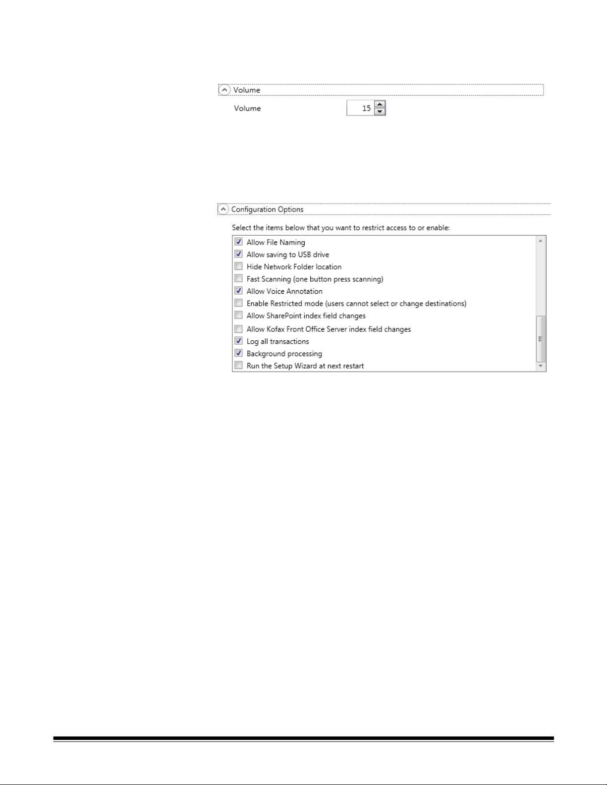
Volume — allows you to adjust the master volume of the Scan St a tion.
This will typically affect the speaker sound from the FAX modem.
NOTE: If you do not hear the fax dial tone after changing the
volume, you may need to restart the Scan Station.
Configuration Options — provides the following options.
• Allow File Naming — allows a user to name both the folder and the
file name prefix used when scanning to either a network folder or a
USB drive. The folder will be appended to the path of the selected
destination and the file name will be used to create the actual file.
The user will optionally be able to turn on or off the date and time
stamp used when creating the file name.
• Allow Saving to USB drive — allows you to enable scanning to a
USB drive. This may be useful in more secure environments where
tighter control is required.
• Hide Network Folder location — enable this option to provide a
more secure environment by partially hiding the location of the
network folder. If this option is enabled, only the end of the network
folder path will be displayed on the Scan Station touchscreen. For
example: \\server\myfolder will be displayed as: ...\myfolder.
• Fast Scanning (one button press scanning) — allows a user to
scan instantly without waiting for the 10-second delay, the Settings
Review screen or the Destination Review screen to be displayed. A
message will only be displayed if the scan session was unsuccessful.
• Allow Voice Annotation — when ena bled, allows a user to record a
voice annotation for each batch of scanned documents. By default,
this option is enabled.
A-61796 December 2013 4-5
Page 31

• Enable Restricted mode (users cannot select or change
destinations) — when enabled, will only allow users to select a predefined job from the Scan St ation touchscreen. These jobs cannot be
changed by the user.
• Allow SharePoint index field changes — when enabled, allows a
user to change existing index fields.
• Allow Kofax Front Office Server index field changes — when
enabled, allows a user to change existing index fields.
• Log all transactions — the Scan S t ation can log all transactions (all
activity related to login, scanning and saving to destinations) to a
separate transaction file. This file is in XML format and can be
downloaded from the Scan Station. This is useful in environments
that are security-minded or where transactions are used for billing. By
default, all transactions are logged (checked). You can disable
transaction logging by unchecking the checkbox.
• Background processing — allows you to select how jobs are
processed. If background processing is selected, all jobs will be
submitted to a queue and, by default, be processed in a first in, first
out (FIFO) manner. This allows a user to start a second scan job
immediately after the first job is scanned, even if the first scan job is
still being processing.
• Run the Setup Wizard at next restart — when selected, the Setup
Wizard will run when the Scan Station restarts, which provides a
step-by-step procedure allowing you to select configuration options
(e.g., time, date, etc.) when the Scan Station is restarted.
NOTE:The Setup Wizard is run from the Scan Station (not the
Kodak Scan Station 700/720EX - Scanner Administration
application).
4-6 A-61796 December 2013
Page 32

Date — allows you to set the date format on the Scan Station.
1. From the Date Separator drop-down list, select a symbol to use as a
separator in the date format.
2. Select how you want the date displayed on the Scan Station
touchscreen by selecting a format (year, month, day) from the Date
Format drop-down list.
Time — allows you to set the time format on the Scan Station.
1. Select the desired Time Zone.
2. If you want the Scan Station to automatically adjust for daylight
savings time, check the Daylight Savings check box.
3. Select either 12 Hour or 24 Hour time format from the Clock drop-
down list.
4. Select the desired separator symbol that will be displayed in the
time format from the Time Separator drop-down list.
5. Select the hours, minutes, seconds of how you want the time format
to be displayed: hh:mm:ss, h:mm:ss, hh:mm or h:mm.
Power Saver (for Scan Station 700 only) — use the up and down
arrows to set the amount of time the Scan Station needs to be inactive
before it goes into power saver mode. The default is 15 minutes.
Depending on the options you selected on the main Device Settings
screen, you will have the option of clicking Next which will display the
next device you want to configure, or Finish which will return you to the
Configuration tab.
A-61796 December 2013 4-7
Page 33

Configuring email settings
For the Scan Station to send documents to email recipients, you must
define how the Scan Station will access your email server.
1. Check Email Server and click Next.
2. Enter an IP address or a fully qualified domain name of your SMTP
server in the Email Server Address field.
3. If your SMTP server requires it, enter a Username, Password and
an optional Domain name for the email server account that the
Scan Station will log into.
4. Most email servers communicate on port 25. If your email server
communicates on a different port, select the desired port number.
5. Select Authentication Scheme to select the specific SMTP
Authentication Scheme used by your email server. Select from the
following options:
• Use Strongest
• None
•Plain
• Login
• MD5 Challenge Response
• NTLM
NOTE: Use Strongest will select the strongest available
authentication scheme reported by the email server. For
more information on authentication schemes, consult your
network administrator.
6. Use the up and down arrows to select the desired Maximum
Attachment Size of an email attachment that can be sent
successfully (1 to 99 MB in 1 MB increments).
4-8 A-61796 December 2013
Page 34

7. Enter the email address where you want a notification to be sent
that an email could not be delivered by the Scan Station in the
Return Email Address field. This email address will also be put in
the email From field.
8. If you do not want the user to have the ability to enter an email
address that is not currently in the address book, uncheck the Allow
custom Email Addresses checkbox.
9. If you do not want the user to have the ability to enter information in
the subject line when scanning to email destinations, uncheck the
Allow custom Email Subject checkbox.
10.Select the security type to setup a secure connection to your email
server. Selections are: None, SSL or Use StartTLS.
• SSL: select this option if your email server requires Secure
Socket Layer (SSL).
• Use StartTLS: select this option if you want to enable a secure
SMTP connection.
NOTE: If selected, make sure your email server is configured to
use St artTLS. If it is not, the Scan Station will fail to send an
email.
11.Click Test Connection if you want to check to be sure your settings
are correct. When finished, a Success or Failure message will be
displayed. If the test connection failed, verify that all of your settings
are correct and make any necessary changes, until a Success
message is displayed.
NOTE: You may need to use the scroll bar to access the Test
Connection button.
Depending on the options you selected on the main Device Settings
screen, you will have the option of clicking Next which will display the
next device you want to configure, or Finish which will return you to the
Configuration tab.
A-61796 December 2013 4-9
Page 35

Configuring Active Directory Server settings
If you selected to configure the Active Directory Server, proceed with
the following steps. If not, go to the section that describes the next
device you want to configure.
The Active Directory Server allows you to setup a central location for
network administration and security.
1. Enter an IP address or a fully qualified domain name in the Active
Directory Server Address field.
2. If your server requires it, enter a Username, Password and an
optional Domain name for the Active Directory Server account that
the Scan Station will log into.
3. Most Active Directory Servers communicate on port 389. If your
Active Directory Server communicates on a different port, select t he
desired port number.
4. The Base DN (Distinguished Name), Search Field Tag, Email
Address Tag, and Full Name Field Tag are strings that define the
search criteria for the Active Directory Server. See your network
administrator for the specific format of these strings. When you have
the correct format, enter the Base DN, Search Field Tag, Email
Address Tag and Full Name Field Tag.
5. In the Home Directory Tag field enter the name of the tag in your
Active Directory Server that defines where the user’s home directory
is located. This requires the home directory to be defined in your
Active Directory Server database.
If Force User Login is checked, when the user logs into the Scan
Station, their home directory will automatically be used as their
destination.
4-10 A-61796 December 2013
Page 36

6. Enter the Active Directory Server Fax Field Tag for the tag to use
when searching the Active Directory Server for fax numbers. For
more information, contact your network administrator for the exact
string to use (e.g., facsimiletelephonenumber).
7. Select the maximum number of records to display when performing
a search from the Search Results To Return field. Select a number
from 1 to 1000.
NOTE: You may need to use the scroll bar to access the Security
Type, Force User Login and the Test Connection options.
8. Select the Security Type to setup a secure connection to your
Active Directory Server. Selections are: None, SSL or TLS.
• If you select SSL or TLS, the Certificate and Certificate
Password fields will be displayed allowing you to select a
certificate file.
• Some certificates require a password. If your certificate requires
a password, enter the password.
9. If you check Force User Login, it requires the user to login before
beginning a scan session. At login, the user will have to enter a user
name, password and domain.
NOTE: A default administrator account is available for logging onto
the Scan Station after enabling Force User Login. Initially
the password will be “blank” and it is up to you to set this
password to prevent user access to administrative
functions. For information on this password, see the section
entitled, “Configuring your device options” earlier in this
chapter.
10.Click Test Connection if you want to check to be sure your settings
are correct. When finished, a Success or Failure message will be
displayed. If the test connection failed, verify that all of your settings
are correct and make any necessary changes, until a Success
message is displayed.
Depending on the options you selected on the main Device Settings
screen, you will have the option of clicking Next which will display the
next option you want to configure, or Finish which will return you to the
Configuration tab.
A-61796 December 2013 4-11
Page 37

Configuring Fax settings If you selected to configure Fax, proceed with the following steps.
NOTE: Dial-up fax settings are for the Scan S t ation 720EX only. Dial-up
configuration settings will be ignored if they are sent to a Scan
Station 700.
Fax settings can be configured to allow the Scan Station to send and
receive faxes.
NOTES:
• Steps 1-8 are for the dial-up modem only (Scan Station 720EX).
• This procedure allows you to configure a number of email addresses.
For a summary of the different email addresses and their use, see
the chart at the end of this section.
1. If desired, enter a fax number in the Sender’s Fax Number field.
This number will be displayed on the banner of outgoing faxes.
2. If your phone system requires a number to get an outside line, enter
the prefix that the user needs to enter to access an outside line
(e.g., 9, is frequently used and a comma “,” may be used to insert a
pause) in the Outside Line Prefix field. Each comma pauses the
dialing sequence for about 3 seconds. You can use multiple
commas to increase the pause time.
3. Select Modem Country Code to display a list of countries and the
associated codes that configure the modem for use in the selected
country.
4-12 A-61796 December 2013
Page 38

4. Enter the number of times the Scan Station will attempt to send a
fax in the Fax Failure Retries field.
5. Enter the number of minutes the Scan Station will wait between
attempting to send a fax in the Delay Between Retries field.
NOTE: If the fax service is not able to send a fax to the recipient,
an email will be sent to the sender’s email address (if
available). Otherwise, the message will be sent to the
administrator’s email address. Included in the message will
be: the fax TIFF image, the sender and recipient’s fax
number and the error response.
6. If you want someone to be notified every time a fax is sent (success
or failure), enter the email address of the person/group who should
be notified in the Fax Notification Email Address field.
7. Check Allow Fax Notification if you want “success” and “failure”
notifications to be sent to an email address, printer or both, every
time a fax is sent. If left unchecked, no notifications will be sent.
NOTE: Fax/Printer notifications can only be configured after
destinations have been defined and at least one printer has
been defined. For information about setting up a printer see
the section entitled, “Setting up a printer destination” in
Chapter 6.
8. If you want the user to be able to change the email address of the
person/group that is notified when a fax is sent, check the Allow
Custom Fax Numbers checkbox.
9. Enter the LAN fax server domain name for customers who use an
email-to-fax service (e.g., Nextiva). This setting configures how LAN
fax destinations will be sent.
NOTE: This only works with an email-to-fax service that only
requires sending to a particular fax number on that domain
where no login is required.
A-61796 December 2013 4-13
Page 39

10.When you have finished entering information on this screen, click
Next. The following screen will be displayed.
11.If you do not want to allow the Scan Station to receive faxes, click
No; otherwise click Yes and enter the required information in the
Incoming Fax Configuration fields.
4-14 A-61796 December 2013
Page 40

If desired, enter one or more of the following:
• a fully qualified path name to the network folder where the
incoming fax will be saved.
• the email address of the person/group where the incoming fax
will be delivered.
• the printer name where the incoming fax will be sent for printing.
• the FTP site where the incoming fax will be saved.
12.Check Save as PDF if the incoming fax will be saved as a PDF file.
NOTES:
• If you configure the Scan Station to receive incoming faxes, you
must define at least one destination; otherwise the faxes will not
be delivered.
• In order for faxes to be routed to either a printer, network folder or
FTP site, these destinations must be created in advance in order
to be selected.
13.Click Finish.
Email address summary Following is a summary of the different email addresses that can be
configured for Fax and Fax to Email.
Email address and description Where it is configured
Administrator
• Fax delivery failure notifications will be sent to this
email address if the fax sender’s email address is
unknown.
• Incoming fax failures will also be sent to this email
address.
Fax Notification
A notification is sent to this email address for every fax
sent - Success and Failure.
Custom or Sender
A notification is sent to an email address entered by the
user on the Scan Station at the time the document(s) is
scanned and faxed - Success and Failure.
LAN fax server
This is the email address of a LAN fax server that
receives faxes at an email address such as 5555555@faxserver.com.
Incoming faxes
The Scan Station can be configured to deliver incoming
faxes to this email address.
• Device Settings screen
• Email Server
• Return Email Address field
• Device Settings screen
• Fax - Step 2 of 3
• Fax Notification Email Address field
• Allow Fax Notification checkbox must be checked
• Device Settings screen
• Fax - Step 2 of 3
• Allow Custom Fax Numbers checkbox must be
checked
• Allow Fax Notification checkbox must be checked
NOTES:
• Customer email address is entered on the Scan
Station by the user when the fax is sent.
• A fax notification will also be sent to the Fax
Notification email address.
• Device Settings screen
• Fax - Step 2 of 3
• LAN Fax Server Domain Name checkbox must be
checked
• Device Settings screen
• Fax - Step 3 of 3
• Incoming fax configuration: Email Address
A-61796 December 2013 4-15
Page 41
5 Defining Scan Settings
Scan Settings..................................................................................5-3
Black and White Settings................................................................5-5
Color Settings .................................................................................5-6
Advanced Settings..........................................................................5-8
PDF Settings.................................................................................5-11
Filename Settings.........................................................................5-12
Scan Settings provide basic image processing settings, such as, color/
grayscale/black and white, output file format, compression, and some
advanced options like Hole Fill, Streak Filter, etc.
1. Select Edit>Scan Settings.
The Setup Scan Settings screen will be displayed.
A-61796 December 2013 5-1
Page 42

2. Click the Add icon. The following screen will be displayed.
3. Make selections from any of the categories (e.g., Black and White
Settings, Advanced Settings, etc.).
NOTE: For a detailed description about the options, see the
sections that follow.
4. When finished making selections, click Next.
5. Enter a name in the Scan Settings Name field that describes this
scan setting.
6. Click Finish.
5-2 A-61796 December 2013
Page 43
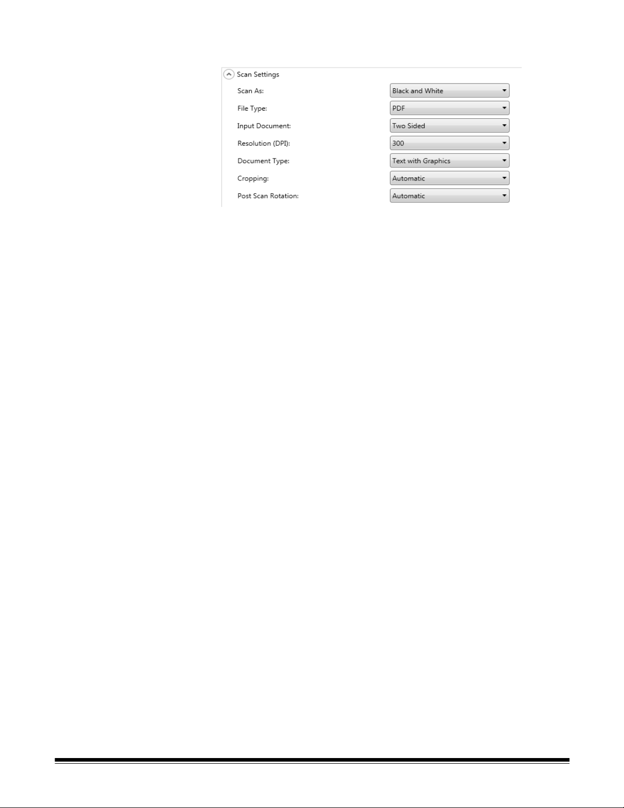
Scan Settings Scan Settings
Scan As — select how you want documents to be scanned. Selections
are: Color, Grayscale, Black and White.
File Type — select one of the following options:
• JPEG: this option is only available for Color or Grayscale. If your
Scan As selection is Black and White and JPEG is selected, your
Scan As selection will automatically change to Color.
• TIFF - Single Pages: creates multiple files, one for each side of a
scanned page. Selections are: None (Uncompressed), Group 4 or
JPEG compression.
• TIFF - Multi Page: creates one file that contains all of the scanned
pages. Selections are: None (Uncompressed), Group 4 or JPEG
compression.
NOTE:The compression setting depends on the Scan As selection.
If the Scan As selection is Black and White, select a
compression setting from the Black and White Settings. If the
Scan As selection is Color or Grayscale, select a
compression setting from the Color Settings.
• PDF: creates a PDF document. See the section entitled, “PDF
Settings” later in this chapter for more information.
• DOC: creates a Microsoft Word document.
• RTF: creates a Rich Text Format file which can be read by a number
of applications.
• XLS: creates a Microsoft Excel spreadsheet.
NOTES:
• When scanning to DOC, RTF and XLS, optical character recognition
is performed on the scanned image. The .doc, .rtf or .xls file produced
is based on the OCR results; therefore, the result may not be
identical to the original.
• When you select DOC, RTF or XLS, the Language option will be
displayed. Select the language you want used to generate the file.
A-61796 December 2013 5-3
Page 44

Input Type — select one of the following options:
• Two Sided: the Scan Station will scan the front and back in a single
pass.
• One-Sided - Face Down: if you select this option, the documents
must be put in the input tray face down (the side you want to scan
facing the input tray).
• One-Sided - Face Up: if you select this option, the documents must
be put in the input tray face up (the side you want to scan facing
toward you).
Resolution (DPI) — select 100, 150, 200, 240, 300, 400 or 600 dpi.
Higher resolutions produce better quality images, but larger file sizes.
Document Type — select one of the following options:
• Text with Graphics: the documents contain a mix of text, business
graphics (bar graphs, pie charts, etc.) and line art.
• Text: the documents contain mostly text.
• Photographs: the documents contain mostly photographs.
Cropping — select one of the following options:
• Automatic: automatically detects the border of an image and
straightens it if necessary.
• Aggressive: automatically detects the border of an image,
straightens it if necessary, and eliminates any residual black border
on any image edges. In order to achieve this, there is a possibility
that a small amount of image data from the edge of the document
may be lost.
Post Scan Rotation — select None or Automatic. If you select
Automatic, the Scan Station will analyze each document to determine
how it was fed and rotate the image to the proper orientation.
5-4 A-61796 December 2013
Page 45

Black and White Settings The Black and White settings will be grayed out, if your Scan As
selection is Color or Grayscale.
Compression — you can select None or Group 4.
Conversion Quality —allows you to select Best (iThresholding) or
Normal (ATP).
• Best (iThresholding) — the Scan Station dynamically evaluates
each document to determine the optimal threshold value to produce
the highest quality image. This allows scanning of mixed document
sets with varying quality (such as faint text, shaded backgrounds, or
color backgrounds) to be scanned using a single setting thus
reducing the need for document sorting. When Best is selected, only
Contrast can be adjusted.
• Normal (ATP) (Adaptive Threshold Processing) — separates the
foreground information in an image (e.g., text, graphics, lines, etc.)
from the background information (i.e., white or non-white paper
background). When Normal is selected, you can adjust both
Threshold and Contrast.
Contrast — adjusts the amount of the image foreground which is kept
or attenuated. Decreasing this setting will reduce the amount of noise at
the expense of possibly losing faint text. Increasing this setting will help
make faint text more visible at the expense of creating more noise.
Threshold — aids in controlling the level at which a pixel is considered
black or white. Decreasing this setting will make the image appear
lighter, and can be used to subdue background noise. Increasing this
setting will make the image appear darker, and can be used to help pick
up light information. This options range from 0 to 255.
Noise Filters — select one of the following options:
• Lone Pixel: reduces random noise by converting a single black pixel
to white when it is completely surrounded by white pixels or by
converting a single white pixel to black when it is completely
surrounded by black pixels.
• Majority Rule: sets each pixel based on its surrounding pixels. The
pixel will become white if the majority of the surrounding pixels are
white and vice versa.
Image Filters — you can select None or Halftone Removal. Halftone
Removal enhances dot matrix text and images with halftone screens
(e.g., newspaper photographs).
A-61796 December 2013 5-5
Page 46

Color Settings
Compression — select JPEG or None. JPEG creates multiple files,
one for the front and back of a page. If JPEG is selected, you can select
a Quality option of: Draft, Good, Better, Best or Superior.
Quality — allows you to select a Draft, Good, Better, Best or
Superior quality option. When saving a file as PDF, predefined
resolution settings will be used when selecting Good (150 dpi), Better
(200 dpi), and Best (300 dpi). The Scan Station dpi settings will not be
used when scanning in PDF mode.
NOTE: The quality settings impact the final size of the file (Draft
producing the smallest file size and Superior producing the
largest file size).
Brightness and Contrast — you can select None, Automatic or
Manual. If you select Automatic, the Scan Station will select the
values to use. If you select Manual, you can set specific values that will
be used for all images:
• Brightness: changes the amount of white in the color or grayscale
image. The values range from 1 to 100.
• Contrast: enhances or diminishes the differences between light and
dark pixels.
NOTE: If you are scanning documents with faint text added for security
and dark text that you want to keep for OCR, decrease this
setting.
5-6 A-61796 December 2013
Page 47

Color Balance — select one of the following options:
• None
• Automatic: adjusts the white background of each document to pure
white. This option compensates for the variations that occur between
different weights and brands of paper. This is not recommended for
use with photographs.
• Automatic - Advanced: for advanced users that want to further
adjust the Automatic option.
- Aggressiveness: allows you to adjust the extent of the variation.
Increasing this value can help with documents that have yellowed
due to age. The values range from -2 to 2.
• Manual: allows you to set specific values that will be used for all
images:
- Red: changes the amount of red in the color image. The values
range from 1 to 100.
- Green: changes the amount of green in the color image. The
values range from 1 to 100.
- Blue: changes the amount of blue in the color image . The values
range from 1 to 100.
NOTE: Color Balance is not available for grayscale images.
Sharpen —controls the enhancement of edges in the document.
Options include: None, Normal, High and Exaggerated.
Background Smoothing — using this option for documents or forms
with a background color will help produce images with a more uniform
background color. This option improves image quality and may reduce
file size.
• None
• Automatic: smooths up to three background colors.
• Automatic - Advanced: for advanced users that want to further
adjust the Automatic option.
- Aggressiveness: allows you to adjust the extent to which the
background(s) are determined. The values range from -10 to 10.
A-61796 December 2013 5-7
Page 48

Advanced Settings
• Hole Fill: allows you to fill in the holes that are around the edges of
your document. The types of holes that are filled include: round,
rectangular, and irregularly shaped (e.g., double-punched or those
having a slight tear that could have occurred when the document was
removed from a binder).
• Blank Image Detection: used to detect blank pages (e.g., the back
side of a document), so these pages can be discarded. If you select
this option, you can select Based on Document Content where you
can select a percentage where document images that fall below the
selected percentage will be discarded.
• Image Edge Fill: fills the edges of the final electronic image by
covering the area with the selected color.
-None
- Automatic: the scanner will automatically fill the edges of the
image using the surrounding color.
- Automatic - include tears: in addition to filling the edges, the
Scan Station will also fill in tears along the edge of document.
- White: allows you to enter values for the Top, Bottom, Left and
Right margins.
- Black: allows you to enter values for the Top, Bottom, Left and
Right margins.
5-8 A-61796 December 2013
Page 49

• Streak Filter: allows you to configure the Scan Station to filter
vertical streaks from your images. Streaks are lines which may
appear on an image and are not part of the original document.
Streaks may be caused by contaminants on your documents (e.g.,
dirt, dust or frayed edges) or by not following the recommended
cleaning procedures for your Scan S t ation. Click S treak Filter to turn
this option on where you can select an Aggressiveness value which
allows you to adjust the extent at which the streaks are filtered. The
values range from -2 to 2.
• Color Dropout — used to eliminate a form's background so that only
the entered data is included in the electronic image (e.g., remove th e
form’s lines and boxes). For black and white images, these settings
affect the grayscale version of the document which the Scan Station
analyzes to produce that electronic image. This option is only
applicable for grayscale and black and white images. Select one of
the following options:
- None
- Multiple: drop s colors other than dark shades (e.g., black or dark
blue ink)
- Predominant: drops the predominant color
-Blue
-Green
-Red
When you select Multiple or Predominant, you can adjust the
Aggressiveness value to the extent at which colors are dropped.
The values range from -2 to 2. The default is 0.
Combine Front and Back Images — typically one image is created for
a document the front side and another image is created for the back
side. Turn this option on if you want one image that contains both the
front side and back side of the document. Select one of the following
options:
• None
• Front on Top: front side will be above the back side within the
image.
• Front on Bottom: back side will be above the front side within the
image.
• Front on Left: front side will be to the left of the back side within the
image.
• Front on Right: back side will be to the left of the front side within the
image.
A-61796 December 2013 5-9
Page 50

Multifeed Ultrasonic Detection — multifeed detection aids in
document processing by detecting documents that may go through the
feeder overlapped. Multifeeds can happen due to stapled documents,
adhesives on documents, or electrostatically charged documents.
Check this option if you want to enable a Multifeed Response when a
multifeed is detected.
• Multifeed Sensitivity — controls how aggressively the scanner will
work to determine if more than one document is fed into the scanner.
Multifeeds are triggered by detecting air gaps between documents.
This allows multifeed detection to be used with job sets containing
documents with mixed thicknesses.
- Low: least aggressive setting and is less likely to detect labels,
poor quality, thick or wrinkled documents as multi-fed documents.
- Medium: use if your job set has varying document thicknesses or
labels attached to the document. Depending on the label material,
most documents with labels should not be detected as a multi-fed
document.
- High: the most aggressive setting. This is a good setting to use if
all documents have a thickness no greater than 20-lb. bond paper.
NOTE:Regardless of the setting, “sticky” notes may still be detected
as multi-fed documents.
• Multifeed Response — select what action you want the Scan
Station to take when a multifeed is detected. With all options, the
condition will be logged in the Scan Station.
- Continue Scanning: the Scan Station will continue to scan.
- Stop Scanning: scanning will stop and you will have to option to
continue scanning or cancel the batch. Verify that the paper path
has been cleared and restart the scan session from the scanning
application.
Maximum Document Length (in.) — allows you to select the
maximum length of the documents in your job. If the Scan Station
detects a document longer than this value, it will determine tha t a paper
jam has occurred. The default is 14 inches. Maximum length is 160
inches; minimum length is 2.5 inches.
Reverse Page Order — if enabled, the Scan Station will reverse the
order of the scanned images from the order in which the documents
were scanned.
Allow Adding Pages To Scan Job — when enabled, the user can
continue to add pages to a scan job. After all pages in the input tray
have been scanned, a message will be displayed asking if they want to
add more pages. If the user selects Yes, the additional pages will be
scanned and the message will be displayed again until the user select s
No, or the 30-second timeout has occurred.
5-10 A-61796 December 2013
Page 51

PDF Settings
Quality — allows you to select a Good, Better or Best quality option.
When saving a file as PDF, predefined resolution settings will be used
when selecting Good (150 dpi), Better (200 dpi), and Best (300 dpi).
The Scan Station dpi settings will not be used when scanning in PDF
mode.
Searchable — creates a single- or multi-page document that contains
both text and image data. OCR (Optical Character Recognition)
technology is used to extract text information from the scanned image
data. When you select this option, the Language option is displayed.
Select the language you want used to generate the PDF file.
NOTE: This option specifically turns on OCR. OCR can also be enabled
by selecting XLS, DOC and RTF output.
Single Pages — creates a PDF file for every page scanned. If
scanning a two-sided document, a separate file will be created for both
the front and back page.
Secure — allows the user to enter a password that will be used to
encrypt the file before the file is delivered. The password will be sent in
a separate email when Email is one of the destination selections.
PDF/A — this option is specialized for the digital preservation of
electronic documents and is used if you want to generate a PDF that
will be used for long term needs.
A-61796 December 2013 5-11
Page 52

Filename Settings
File Name Settings allow you to define values that determine the
locations (directories or subdirectories) and file name used when
creating scanned documents. You can define a folder name where
scanned documents will be placed when scanning to a network folder,
FTP location or USB drive destination. You can also define the file
name prefix that will be applied to every scanned document created.
Scanned documents are created with this prefix and have an optional
date and time stamp appended to the prefix. For example, if you d efine
a prefix of receipts and a folder name of 2012, the scanned document
file name will have the format: receipts_20120117_092219.tif and is
placed in a folder called 2012.
• Device Name — allows you to use the Scan Station name in the file
name or as part of the file path.
• Date — allows you to enter the date in the file name or as part of the
file path.
• Time (hhmmssff) — allows you to add the time (hhmmssff) in the file
name or as part of the file path.
• Sequence Number — allows you to use a sequence number in the
file name or as part of the file path.
• Text — allows you to type in text that will be used in the file name or
as part of the file path. This is limited to the maximum characters
allowed by the target operating system.
• Directory Separator — allows you to use a separator in the file
name or as part of the file path.
NOTES:
• Use the up and down arrows to reorder the items in the boxes.
• When entering values, the sample file name will be displayed in the
text box at the bottom of the screen.
• When you select Text, Date or Sequence Number additional
selections will be displayed on the right.
5-12 A-61796 December 2013
Page 53

6 Creating Destinations
Contents Accessing the Destinations screen.................................................6-1
Destination layout and terminology.................................................6-3
Setting up an email destination.......................................................6-4
Importing an email address book................................................6-6
Setting up a network destination .....................................................6-8
Setting up a printer destination.....................................................6-10
Setting up a FTP site ....................................................................6-14
Setting up a fax or fax to email destination...................................6-18
Adding a SharePoint group ...........................................................6-19
Adding a Kofax Front Office Server group....................................6-21
This chapter provides procedures for adding destinations (e.g., email,
network folder, printer, FTP, etc.).
Accessing the Destinations screen
1. Select Edit>Destinations.
A-61796 December 2013 6-1
Page 54

The Setup Destinations screen will be displayed.
2. Click the Add icon to display the Destinations screen. The
Destinations screen allows you to create destinations for: Email,
Network, Printer, FTP, Fax, Email to Fax, SharePoint and Kofax
Front Office Server.
6-2 A-61796 December 2013
Page 55

3. Select the destination type you want to create. When you select a
Destination type
Destination group
Destination
destination type, a recommended name for the destination will be
displayed in the Destination Name field. You can change this name
by entering a name that is meaningful to you. This is the name that
will be displayed on the Scan Station touchscreen.
4. Click Next. The application will step you through each destination
configuration.
NOTE: For a detailed description about the different destination
types see the sections that follow.
Destination layout and terminology
After setting up a destination, a screen similar to the one below will list
your destination types, destination groups and destinations.
A-61796 December 2013 6-3
Page 56

Setting up a email destination
1. Select Edit>Destinations. The Setup Destinations screen will be
displayed.
2. Click the Add icon to display the Destinations screen.
3. Select Email.
4. Click Next.
5. Enter a name in the Description field and an email address in the
Enter a complete email address field where you want the scanned
documents to be sent.
• Search allows you to search the network address book for email
addresses. Any addresses found while searching can be added
to the currently selected email group.
NOTES:
- The network address book is the one associated with the
SMTP server configured under Device Settings (Email
server).
- If more than 20 addresses are found that match the search
criteria, you may want to refine your search by adding more
information, such as the first name of the person you are
searching; for example, “smith joe” instead of just “smith”.
- Wildcards can be added before and after the search criteria.
- The Search function relies on the Active Directory Server
device settings specified to function correctly . See the se ction
entitled, “Configuring Active Directory Settings” in Chapter 4
for more information.
• Import allows you to import a CSV file. See the next section
entitled, “Importing an email address book” for more information.
6-4 A-61796 December 2013
Page 57

6. Click Finish. The following screen will be displayed showing the
email destinations and groups.
7. If you want to add more email destinations within the same email
destination group, select the Add icon and repeat Steps 5 and 6.
8. T o add ano ther email destination grou p, select the email destination
type and then click the Add icon, otherwise, click Finish.
A-61796 December 2013 6-5
Page 58

Importing an email address book
CSV files are data files that represent database information. Each row
contains data values that are separated by a comma. Each comma
found on a line of text represents a column of data from the original
database. The example below shows typical data exported from
Microsoft’s Outlook Express.
NOTE: The first row may contain the data column header information
and not actual data.
First Row
First Name,Last Name,Email Address
Smith,John,johnsmith@rochester.rr.com
Tom,Brown,Tombrown123@yahoo.com
William,Doe,wdoe@msn.com
Outlook Express allows you to export your email address book to a
comma-separated file. When you export your email address book, you
can select which data columns you want to export.
NOTE: Other email programs may not allow you to select which data
columns to export.
It is recommended that you only export the first name, last name, and
email address.
1. Click Import. The Import Email Addresses dialog box will be
displayed.
2. Enter the file name in the File field that contains the email addresses
you want to import. If necessary, use the Browse button to locate
the file.
6-6 A-61796 December 2013
Page 59

3. Many email client applications automatically export the column
headings as the first row of data. If you do not want to import the
column headings as the first row, check Skip first row of data.
NOTE: Some email applications also export the data with
additional quote characters surrounding the data. The
quote characters will be removed while importing data.
4. Enter the column numbers where the First Name, Last Name and
Email Address appear in the CSV file.
After selecting a CSV file and column locations, a preview will be
displayed showing the results of the file Column Location
selections. If the column selections are changed, the preview will
reflect these changes.
For example, if the three File Column Location values are 1, 2, and
3 the preview would display the following:
First Name Last Name Email Address
The First Name and Last Name are combined to form the email
address display name. The Email Address is used to create the
email address.
If all three File Column Location values were set to 1, then the
preview would look like this:
First Name First Name First Name
5. Click Import. The email addresses will be added to the selected
email group.
A-61796 December 2013 6-7
Page 60

Setting up a network destination
1. Select Edit>Destinations. The Setup Destinations screen will be
displayed.
2. Click the Add icon to display the Destinations screen.
3. Select Network.
4. Click Next.
5. Enter a network destination name that is meaningful to you in the
Description field.
6. Enter a fully qualified folder path in the Enter a complete directory
path field and click Finish.
NOTE: You must use a full network path if you are scanning to a
DFS based network.
6-8 A-61796 December 2013
Page 61

The following screen will be displayed showing the network
destination and group.
7. If you want to add more network destinations within the same
network destination group, select the Add icon and repeat Steps 5
and 6.
8. To add another network destination group, select the network
destination type and then click the Add icon, otherwise, click
Finish.
A-61796 December 2013 6-9
Page 62

Setting up a printer destination
The Scan Station uses the Microsoft “Point and Print” technology for
installing print drivers and connecting to network printers. Typically,
network printers are attached to print servers which manage the
scheduling of print jobs for one or more network printers. These print
servers manage print queues for each connected printer and can also
deliver and install print drivers to other network PCs or devices.
NOTE: Before installing printers, be sure you have a Windows 7
compatible driver on the print server or host PC.
The Scan Station can connect to printers in the following ways:
• Connect to a printer that is connected to a print server on a network
domain.
• Connect to a printer that is shared by another computer on a network
workgroup.
• Connect to a network printer that is directly connected to the network
via an Ethernet cable plugged directly into a router or hub.
In each of these scenarios, Microsoft Windows may also require login
credentials for any device requesting access to a network printer.
1. Select Edit>Destinations. The Setup Destinations screen will be
displayed.
2. Click the Add icon to display the Destinations screen.
3. Select Printer.
4. Click Next.
6-10 A-61796 December 2013
Page 63

5. Enter any text that describes the printer in the Description field.
• If you want to connect to a print server on a network domain or to
a printer that is shared by another computer on a network,
continue with Step 6.
• If you want to connect to a network printer that is directly
connected to the network via an Ethernet cable plugged directly
into a router or hub, click the Printer Driver Settings down arrow
and continue with Step 11.
6. Enter the fully qualified path to the printer server and print queue
(e.g., \\printservername\printqueue) in the Enter a complete
directory path field.
7. If the network domain is configured to require authentication to
install a printer driver, enter the Username, Password, and
Domain names.
NOTE: If proper authentication is not provided, the printer and its
driver may not be installed on the Scan Station.
8. Click Finish.The following screen will be displayed showing the
printer destination and group.
9. If you want to add more printer destinations within the same printer
destination group, select the Add icon and repeat Steps 5 - 8.
10.To add another printer destination group, select the printer
destination type and then click the Add icon, otherwise click Finish.
A-61796 December 2013 6-11
Page 64

If you want to configure a printer that is directly connected to the
network, follow Steps 11 - 18. The printer must first be “shared” from a
computer on the network in order to download the print driver. The
shared printer must also be configured to provide a Windows 7 driver
for the printer. Once shared, you need the driver name and port name
from this computer.
11. In the Enter a complete directory path field, enter the network printer
IP address and print queue (e.g., \\192.168.1.136\printQueue
Name).
On the PC that is sharing the printer:
12.Click Start>Settings>Printers and Faxes and select the installed
printer.
13.Right-click on the installed printer and select Properties. The
Properties window will be displayed.
14.Write down the Driver Name. The location of this information may
be different for each printer.
6-12 A-61796 December 2013
Page 65

15.On the Ports tab, write down the exact text that appears on the
selected Port value.
NOTE: As shown below, this would be “IP_192.168.2.137”.
16.Return to the Kodak Scan Station 700/720EX - Scanner
Administration application and enter the fully qualified address of
the PC sharing the printer including the share name (e.g.,
\\workgrouppc\BrotherH) in the Address field.
17.With the information from Steps 14 and 15, enter the driver name
and the port name in their respective fields.
18.If you want to add more printer destinations within the same printer
destination group, select the Add icon and repeat this procedure
starting with Step 5.
19.To add another printer destination group, select the printer
destination type and then click the Add icon, otherwise click Finish.
The printer driver will be installed from the sharing PC. A connection
will be made between the printer and the Scan Station using the IP
address entered. After the initial installation, the shared printer
connection is no longer required and the Scan S t ation will be able to
communicate directly with the network printer.
NOTE: If a printer fails to install, check the logfile for the error code.
Search for the error code on the Microsoft website.
A-61796 December 2013 6-13
Page 66

Setting up a FTP site 1. Select Edit>Destinations. The Setup Destinations screen will be
displayed.
2. Click the Add icon to display the Destinations screen.
3. Select FTP.
4. Click Next.
5. Make an entry in the Description, Enter a server name and directory
path, Username and Password fields. The Enter server name and
directory path field should contain a complete path to the FTP site
including the subfolder into which scanned documents will be
placed. For example, ftp://ftp.acme.com/documents would connect
to the FTP site ftp.acme.com and place the scanned documents in
the folder documents.
6. Select the desired Protocol option: FTP, FTPS or SFTP.
• If you select FTP the following options are available:
- If the FTP site communicates on a port other than Port 21,
change the value using the up and down arrows.
- You may optionally select Passive if required by the FTP
server. Passive is commonly used if the FTP site is outside
of the firewall.
6-14 A-61796 December 2013
Page 67

Click the Proxy down arrow to configure the proxy settings.
-Select USER after login for the Proxy Type.
- Enter the Proxy Address in the form of a fully qualified
domain name (e.g., FTP.acme.com) or as an IP address.
- Enter the Username and Password required to access the
proxy server.
- If the proxy server is configured to communicate on a port
other than Port 21, change the value using the up and down
arrows.
• If you select FTPS the following options are available:
- Select an Encryption option: Implicit or Explicit.
When set to Explicit, the Scan Station and the server
negotiate on whether or not to encrypt the data and what form
of encryption should be used. Explicit FTPS is on Port 21.
The Scan Station will accommodate this selection if the
server is capable of receiving encrypted data.
When set to Implicit, the Scan Station is expected to always
send encrypted data. The default port is 990.
Consult the FTP server administrator for the appropriate
encryption option.
- Check Passive if you want to enable Passive port
negotiation.
- Check Require verifiable SSL server certificate if your
network environment is more security conscious and you
require your certificates to be up-to-date and signed by a
certificate authority.
Click the Proxy down arrow to configure the proxy settings.
-Select SOCKS as your Proxy Type.
- Enter the Proxy Address in the form of a fully qualified
domain name (e.g., FTP.acme.com) or as an IP address.
- Enter the Username and Password required to access the
proxy server.
- If the proxy server is configured to communicate on a port
other than Port 1080, change the value using the up and
down arrows.
- Select the appropriate Version for the proxy server. If you do
not know if you should use SOCKS4 or SOCKS5, consult
your administrator.
A-61796 December 2013 6-15
Page 68

• If you select SFTP the following options are available:
- If the SFTP site communicates on a port other than Port 22,
change the value using the up and down arrows. When you
select SFTP, the port value will automatically change to the
default value of Port 22.
- A Private Key file is an encrypted key that is used to access
the SFTP server. There are several different types of Private
Key files. Use the Browse button to select the Private Key
file stored on your computer or network. Consult the SFTP
administrator for the appropriate Private Key file to use.
NOTE:Private Key files encrypted with DSA 2048, 4096 bits
and Putty SSH1 RSA are not supported.
- If you entered a Private Key file and the file is password
protected, you must enter a password. The password is used
to decrypt the Private Key file.
Click the Proxy down arrow to configure the proxy settings. SFTP
supports two proxy types: HTTP and SOCKS.
HTTP
- If you select HTTP as your Proxy Type, enter the Proxy
Address in the form of a fully qualified domain name (e.g.,
FTP.acme.com) or as an IP address.
- Enter the Username and Password required to access the
proxy server.
- If the proxy server is configured to communicate on a port
other than Port 81, change the value using the up and down
arrows.
- Select the appropriate Authentication Type for the proxy
server. If you do not know if you should use LOGIN or NTLM,
consult your administrator.
SOCKS
- If you select SOCKS as your Proxy Type, enter the Proxy
Address in the form of a fully qualified domain name (e.g.,
FTP.acme.com) or as an IP address.
- Enter the Username and Password required to access the
proxy server.
- If the proxy server is configured to communicate on a port
other than Port 1080, change the value using the up and
down arrows.
- Select the appropriate Version for the proxy server. If you do
not know if you should use SOCKS4 or SOCKS5, consult
your administrator.
6-16 A-61796 December 2013
Page 69

7. Click Finish.
8. If you want to add more FTP destinations within the same FTP
destination group, select the Add icon and repeat Steps 5 - 8.
9. To add another FTP destination group, select the FTP destination
type and then click the Add icon, otherwise, click Finish.
A-61796 December 2013 6-17
Page 70

Setting up a fax or email to fax destination
You can setup a destination to a fax machine or email to fax. The steps
are the same for either destination.
1. Select Edit>Destinations. The Setup Destinations screen will be
displayed.
2. Click the Add icon to display the Destinations screen.
3. Select Fax or Email to Fax.
4. Click Next.
5. Enter a name in the Description field and a fax number (or email to
fax number) in the Enter a Fax Number (Email to Fax Number) field,
then click Finish.
6. If you want to add more fax destinations within the same fax
destination group, select the Add icon and repeat Step 5.
7. T o add another fax destination gro up, select the fax destination type
and then click the Add icon, otherwise, click Finish.
6-18 A-61796 December 2013
Page 71

Adding a SharePoint group
1. Select Edit>Destinations. The Setup Destinations screen will be
displayed.
2. Click the Add icon to display the Destinations screen.
3. Select SharePoint.
4. Click Next.
5. Make an entry in the Description field that identifies the destination.
6. Enter the address of the SharePoint server in the Enter a complete
SharePoint website field. This field must contain a complete path to
the SharePoint site.
7. Make an entry in the Username and Password fields.
8. If the SharePoint site you want the user to access is secure, you will
need to enter the certificate file and password by clicking the
Certificate arrow. The SharePoint Certificate options will be
displayed.
• Enter the name of the certificate file in the Certificate field. The
following file extensions are allowed: .cer, .crt, .der, .pfx, .p12,
.p76, and p7c.
• Enter the certificate password that the user should enter to open
and decrypt the certificate file.
9. If your company requires the use of a proxy server before
communicating with the SharePoint site, you must define these
proxy settings by clicking the Proxy arrow.
10.Enter the Proxy Address in the form of a fully qualified domain
name (e.g., proxy.mycompany.com) or as an IP address.
11.Enter the Username and Password required to access the proxy
server.
A-61796 December 2013 6-19
Page 72

12.If the proxy server is configured to communicate on a port other
than Port 80, change or enter the value using the up and down
arrows.
13.In the Documents Path field, enter the path to the folder where the
documents will be scanned. If necessary, use the Browse button to
help locate the folder.
14.If there are required index fields for the selected library, select the
Index Fields button. The Index Fields dialog box will be displayed
that shows the required and optional index fields associated with the
selected library.
NOTES:
• A maximum of 5000 characters is allowed in the Index Notes
field. If you enter more than 5000 characters, a warning message
will not be displayed until you click in another area in the input
field. At that point, when you click OK on the message, all of the
data you entered in the Index Notes field will be deleted.
• The first part of the document path is the library; anything after
that, is a subdirectory. The library contains index fields.
• You must have a certificate before entering index fields
(see Step 8).
• If the index field has a down arrow to t he right of th e index value,
click it to display the value options.
The supported types of index fields are:
Single line of text Multiple lines of text
Choice Number
Currency Date and Time
Lookup Yes/No
Person or Group Hyperlink or Picture
15.If you want to add more SharePoint destinations within the same
SharePoint destination group, select the Add icon and repeat S tep s
5 - 14.
16.T o add another SharePoint destination group, select the SharePoint
destination type and then click the Add icon, otherwise click Finish.
6-20 A-61796 December 2013
Page 73

Adding a Kofax Front Office Server group
1. Select Edit>Destinations. The Setup Destinations screen will be
displayed.
2. Click the Add icon to display the Destinations screen.
3. Select Kofax Front Office Server.
4. Click Next.
5. Make an entry in the Description field that identifies the destination.
6. Enter a server address in the Enter a complete Kofax Front Office
Server address field.
7. If the proxy server is configured to communicate on a port other
than Port 80, select the correct value.
8. Enter the Username and Password required to access the Kofax
Front Office Server.
9. In the Client ID field, enter the Scan Station’s MAC address
(address format: xx-xx-xx-xx-xx-xx). This information can be found
on the About screen on the Scan Station.
10.Select Group or Personal from the Shortcut Type list.
11.Click Browse to locate the Shortcut name. The Select Shortcut
dialog box will be displayed. Select the desired shortcut and click
OK.
A-61796 December 2013 6-21
Page 74

12.Click Index Fields. The Index Fields dialog box will be displayed.
Index fields will vary based on each company’s implementation of
the Kofax Front Office Server.
13.If the Kofax Front Office Server is secure, enter (or browse to) the
name of the certificate file in the Certificate field. The following file
extensions are allowed: .cer, .crt, .der, .pfx, .p12, .p76, and p7c.
14.Enter the certificate password that the user will need to enter to
open and decrypt the certificate file.
15.If you want to add more Kofax Front Office Server destinations
within the same Kofax Front Office Server destination group, select
the Add icon and repeat Steps 5 - 14.
16.To add another Kofax Front Office Server destination group, select
the Kofax Front Office Server destination type and click the Add
icon, otherwise click Finish.
6-22 A-61796 December 2013
Page 75

7 Adding and Managing Groups
This chapter provides procedures for adding and maintaining groups.
Groups are a collection of network users whose names can be
extracted from the Active Directory Server . You can create a group from
the contents of an existing Active Directory Server group and you can
add individual users from the Active Directory Server to your group. For
more information see the section entitled, “Configuring Active Directory
Server settings” in Chapter 4.
Assigning groups Setting up groups makes it easier to restrict access to specific jobs to
groups of users.
1. Select Edit>Groups.
The Setup Groups screen will be displayed.
A-61796 December 2013 7-1
Page 76

2. Click the Add icon to display the Group screen.
3. Enter the desired group name and click Next. Group names can be
anything that is meaningful to you that defines a group of users.
• If you do not want to add groups from your Active Directory
Server , cli ck No, then click Next and continue with Step 8.
7-2 A-61796 December 2013
Page 77

• If you select Yes, the search fields will be displayed allowing you
to find a group name from your Active Directory Server (LDAP).
4. In the Enter the Group to search field, enter the name of the group
that you want to add and click Search.
NOTES:
• If you entered search criteria that generated too many hits, a
message will be displayed asking you to refine your search
criteria.
• Wildcards can be added before and after the search criteria.
5. Select the group(s) that you want to add from the list on the right
and click the left arrow. The groups will be added in the List of
groups box.
6. Repeat Steps 4 and 5 to add other groups to the list.
NOTE: If you want to delete a group from the List of groups, select
the group you want to delete and click the Delete icon.
A-61796 December 2013 7-3
Page 78

7. When finished, click Next.
8. To add users from the Active Directory Server, select Yes.
9. Enter the name of the user you want to add to the group and click
Search.
NOTES:
• If too many addresses are found that match the search criteria,
you may want to refine your search by adding more information,
such as the first name of the person you are searching; for
example, “smith joe” instead of just “smith”.
• Wildcards can be added before and after the search criteria.
10.Select the user(s) to add to the group from the displayed list and
click the left arrow.
11.When you are finished adding all users to your group, click Next.
7-4 A-61796 December 2013
Page 79

A listing of the groups and users will be displayed.
12.Click Finish.
A-61796 December 2013 7-5
Page 80
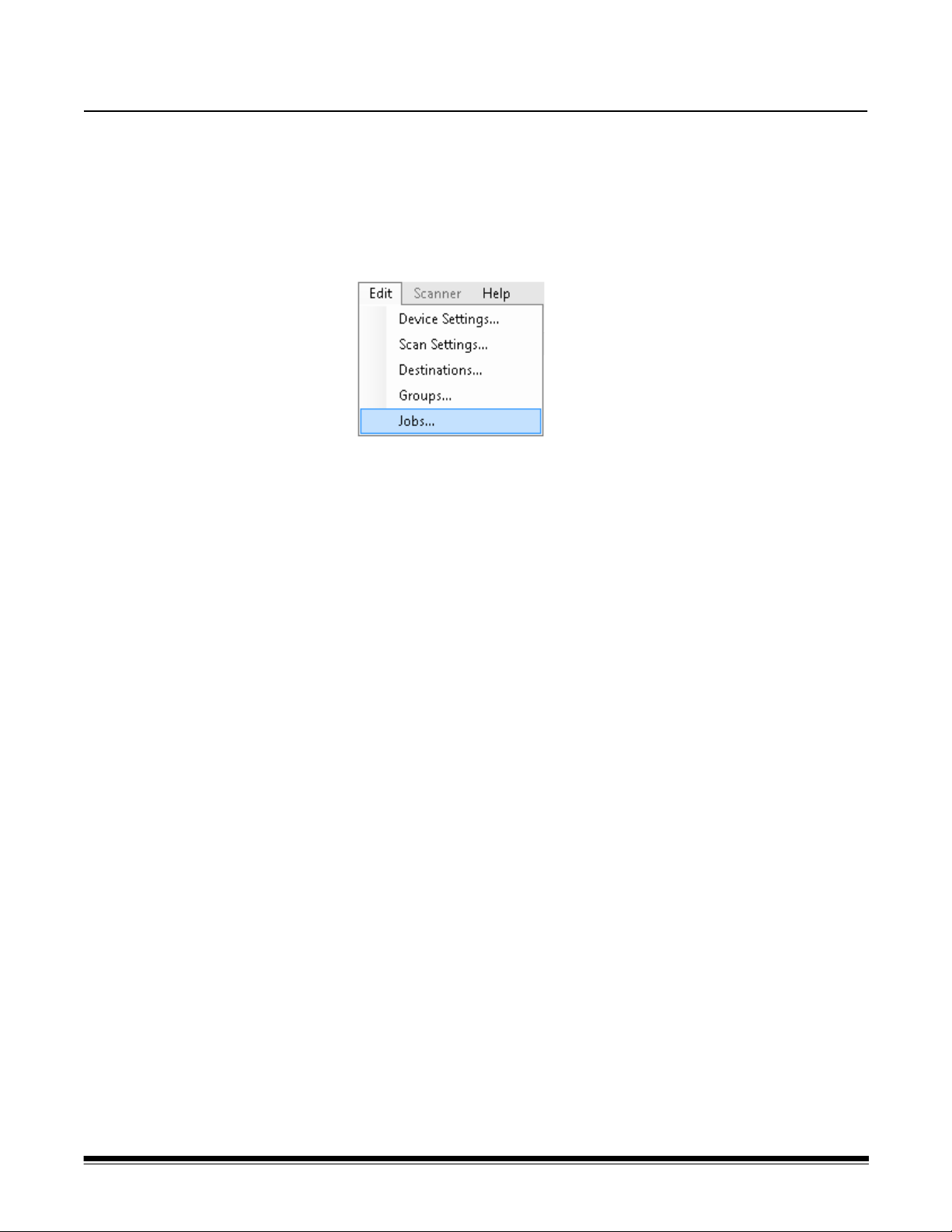
8 Creating Jobs
Because jobs are a collection of scan settings, destinations and groups
of users, it is recommended that you create jobs after you have defined
all of these settings.
1. Select Edit>Jobs.
The Setup Jobs screen will be displayed.
A-61796 December 2013 8-1
Page 81

2. Click the Add icon. The Job screen will be displayed.
3. Enter a job name. As you enter the job name, it will be displayed in
the Job Button Pr eview box. This is how the name will appear on the
Scan Station touchscreen.
4. If desired, you can select an image file that you want to use as a
background to the job name. The maximum image width is 200
pixels; the maximum image height is 130 pixels. Click Browse to
locate the desired image file.
NOTE: If you want an image displayed with the Job name, the
Display Job name together with the image checkbox will be
available. Uncheck this option if you want to display only
the image without the job name.
5. Click Next. The following screen will be displayed.
8-2 A-61796 December 2013
Page 82

6. Select the Scan Settings you want to use for this job and click Next.
The following screen will be displayed.
NOTE: You can also create new scan settings from this screen by
clicking the Add icon.
7. Select the destination(s) where want this job to be sent:
• You can select entire destination groups by clicking the highest
level checkbox for the group.
• You can select individual destinations by clicking on the
destination(s) that is displayed below the group name.
• If you want to create another destination on-the-fly, click the Add
icon. The Destinations screen will be displayed allowing you to
add another destination. For procedures on adding destinations
see Chapter 6, Creating Destinations.
A-61796 December 2013 8-3
Page 83

8. Select Next, then select the group where you want to send this job.
9. When finished, click Next. A summary of your job settings will be
displayed.
10.Click Finish.
8-4 A-61796 December 2013
Page 84

Once a job has been defined and the configuration has been uploaded
to a Scan Station, the Jobs-only screen will be displayed on the Scan
Station touchscreen instead of the normal user interface.
A-61796 December 2013 8-5
Page 85

9 Monitoring and Managing Your Scan Stations
Contents Scanners tab...................................................................................9-2
Toolbar ........................................................................................9-2
Grid view.....................................................................................9-4
Network configuration options.........................................................9-5
Adding a Scan Station.....................................................................9-5
Discovering devices........................................................................9-7
Modifying a Scan Station ................................................................9-8
Deleting a Scan Station...................................................................9-9
Changing a password.....................................................................9-9
Configurations/configuration files..................................................9-10
Updating your Scan Station ..........................................................9-10
Method 1...................................................................................9-11
Method 2...................................................................................9-13
Method 3...................................................................................9-15
Method 4...................................................................................9-16
Method 5...................................................................................9-17
Scan Station Security....................................................................9-18
Password protecting the Scan Station...................................9-19
Retrieving and clearing files..........................................................9-20
Retrieving the Scan Station log file........................................ 9-20
Clearing a log file...................................................................9-22
Retrieving the Scan Station transaction log file .....................9-23
Clearing a transaction log file ................................................9-24
Saving all log files..................................................................9-24
Scan Station details...............................................................9-25
Updating Time/Date remotely.......................................................9-25
Turning off one or more Scan Stations..........................................9-26
Restarting one or more Scan Stations..........................................9-26
Moving one or more Scan Stations...............................................9-27
This chapter provides information for monitoring any Scan S t ations that
have been found on the network and configured.
A-61796 December 2013 9-1
Page 86

Scanners tab The Scanners tab contains the specific data to identify and connect to
Scan Stations on a network.
When the Scanners tab is active, you will have access to the Scanner
menu. The options on the Scanner and Help menus are described in
the section entitled, “Menu options” in Chapter 3.
The toolbar The toolbar provides quick access to commonly used functions. The
toolbar is always displayed. You cannot add, delete or move toolbar
buttons.
Icon Description
Displays the Add Scanner dialog box, which allows you to
choose Scan Stations that will be managed remotely.
Allows you to rename the selected Scan Station and set
network settings.
Allows you to delete the selected Scan Station from the list of
managed Scan Stations.
9-2 A-61796 December 2013
Page 87

Refreshes the grid to display the current state of the Scan
Station:
•Idle
• Scanning
• Processing images
• Sending email
•Saving
•Printing
• Scan completed
•Error
• Cancelled
•Preview
• Sending Fax
• Receiving Fax
• Powering down
• Rebooting
• Updating
•In Use
• Not found
For a description of these states see the section entitled,
“Menu options” in Chapter 3.
Retrieves, displays and allows the saving of the log file on the
selected Scan Station.
Displays and allows the saving of the transaction log file on the
selected Scan Station.
Displays detailed information about the selected Scan Station
(e.g., software version, IP address, etc.).
A-61796 December 2013 9-3
Page 88

Grid view Following is a description of the grid view columns
Scanner Name — displays the name assigned to the Scan Station.
IP Address — displays the IP address that is associated with the Scan
Station.
DHCP — if the Scan Station is configured to retrieve the IP address
using DHCP, this field will be checked. If the Scan Station is configured
to use a statically defined IP address, this field will be blank.
HTTPS — if the Scan Station is configured to communicate using
HTTPS, this field will be checked.
Group — Scan Stations can be associated with a group name. The
column displays the group that the Scan Station is part of. This is set
when adding a Scan Station.
NOTE: This is not the same as the group of users defined when
creating and modifying configurations.
Model — displays the model number of the Scan Station (i.e., 720EX,
700, 5XX).
Status — displays the current status of the Scan Station (e.g., idle,
scanning, updating, rebooting, etc.).
NOTE: When you press F5, the status of the discovered Scan Stations
will be refreshed immediately.
Last Command — displays the last command that was issued by the
administrator including the date, time and the success or failure of the
action performed.
Comment — any comments added by the administrator when a Scan
Station is added will be displayed in this column.
Mac Address — displays the unique identifier of the network adapter.
9-4 A-61796 December 2013
Page 89

Network configuration options
Before you can start adding or discovering Scan Stations you must
know the IP address or the device name; preferably both.
To get the name of your Scan Station:
1. Be sure the Scan Station is on and operational.
2. Click on the Information icon on the Scan Statio n to display the
name and IP address if the Scan Station is connected to a network.
Adding a Scan Station
Before adding a Scan Station to manage remotely, it is suggested that
you obtain the Scan Station name(s) and/or IP addresses and
passwords of the Scan Stations you want to add.
NOTE: The Scan Station will only have an IP address if the Scan
Station is connected to a network and has been configured.
As Scan Stations are added, the main screen will be updated.
1. Select Scanner>Add Scanner . The Add Scanner dialog box will be
displayed.
2. Enter the name of the Scan Station in the Scanner Name field .
NOTE: Acceptable values in this field are: alphanumeric characters
and a dash. No spaces or other symbols are allowed.
3. Enter the IP address. The IP address must be in IPv4 format
xxx.xxx.xxx.xxx.
A-61796 December 2013 9-5
Page 90

4. Enter the device’s password. See the section entitled,
“Configuration your device options” in Chapter 4 for more
information.
NOTE: This field can be left blank. Leave this field blank if the
password has not been changed.
5. If desired, enter a name of the group (or location). This name will be
displayed in the grid view. For example, the Scan Station may be
located in the main branch of a corporation.
6. If desired, enter any additional information that is important to you in
the Comment field. For example, you can enter the name of the
department where the Scan Station is located.
7. Click Add. The Scan St ation name and information will be displayed
on the Kodak Scan Station 700/720EX - Scanner Administration
main screen.
NOTES:
• If the Scan Station is not found or if you are adding a Scan
Station that will be installed on the network at a later time, the
message, There was an error communicating with the device,
would you like to Add it anyway? will be displayed. Click Yes
to add the Scan Station.
• If an incorrect IP address is entered, you may have to delete the
Scan Station information from the Kodak Scan Station 700/
720EX - Scanner Administration main screen and add it again
with the correct information.
8. Follow Steps 1 - 7 to add additional Scan Stations to this group.
9-6 A-61796 December 2013
Page 91

Discovering devices The Discover Devices option allows you to scan a range of IP
addresses to find and automatically register any Scan Station that has
an IP address that falls within the defined range of addresses.
NOTE: The Discover Devices option only works on Scan Stations that
have not had their password changed from the factory default.
This is the password that was set using the Scanner>Add
Scanner menu option from the Scanner tab.
1. Select Scanner>Discover Devices. The Discover Devices dialog
box will be displayed.
2. Enter the first IP address where you want to start the search within a
range of IP addresses in the Start IP Address field.
NOTE: As soon as you click on (or tab to) the End IP Address field,
the end IP address will automatically be filled in with an
address that is 10 greater than the start IP address (e.g.,
Start = 192.168.1.1, End = 192.168.1.10).
3. Enter the last IP address where you want to end the search in the
End IP Address field.
4. Click Search. The search will begin. Depending on the range of the
search, this process may take a few minutes. As IP addresses are
found within the range, they will automatically be registered.
NOTE: If you select an address range that spans the upper two
address segments of the IP address, it may take an
exceedingly long time to discover devices (e.g.,
192.168.1.1 - 192.169.1.1 or 192.168.1.1 - 193.168.1.1).
A-61796 December 2013 9-7
Page 92

Modifying a Scan Station
1. Select Scanner>Modify Scanner. The Modify Scanner dialog box
will be displayed.
2. Make any required changes.
NOTE: If you select Static IP Address, the Static IP Address
dialog box will be displayed allowing you to change IP
address settings.
3. Click OK.
9-8 A-61796 December 2013
Page 93

Deleting a Scan Station
1. Select Scanner>Delete Scanner. The Delete Scanner dialog box
will be displayed.
2. Click Yes.
Changing a device password
1. Select Scanner>Device Password. This device password is used
by the Kodak Scan Station 700/720EX - Scanner Administration to
communicate with the Scan Station.
The Device Password dialog box will be displayed.
2. Enter the Scan Station password in the Current password field.
3. Enter a new password in the New password field.
4. Re-enter the new password in the Confirm new password field.
5. Click OK.
A-61796 December 2013 9-9
Page 94

Configurations/ configuration files
Configurations are a collection of settings that include: Device Settings,
Scan Settings, Destinations, Groups and Jobs. Configurations are
stored in two places: on the PC running the Kodak Scan Station 700/
720EX - Scanner Administration application and on the Scan Station(s)
where the configuration file is uploaded. For more information on the
difference between configurations and configuration files, see Chapter
13, Glossary.
Updating your Scan Station
There are five ways to update your Scan Station:
• Method 1. Uploading configurations and firmware updates using the
Kodak Scan St ation 700/720EX - Scanner Administ ration application.
The Scan Station will automatically recognize the new configuration
or update package and perform an update automatically. See the
section entitled, “Method 1” later in this chapter for more information.
• Method 2. The configuration file and optional firmware update
package is stored on a network drive and the Scan Station is
configured to poll this shared folder at a specific day and time for
updates. See the section entitled, “Method 2” later in this chapter for
more information.
• Method 3. The configuration file is stored on a USB drive inserted
into a Scan St ation. You will be asked if you want to update the Scan
Station’s configuration. If you select Yes, you will be prompted to
update individual items. See the section entitled, “Method 3” later in
this chapter for more information.
• Method 4. The configuration file can be exported to a USB drive for
use in configuring a Scan Station manually. When installing a
configuration file using a USB drive, if the contents of the
configuration file do not match the exact contents of the configuration
file currently stored on the Scan Station, you will be prompted to
update the Scan Station with the configuration on the USB drive. If
you select No, the Scan Station will be placed into local
administrative mode. At this point you can modify most of the Scan
Station’s settings and they will be updated as soon as you remove
the USB drive. See the section entitled, “Method 4” later in this
chapter for more information.
• Method 5. The configuration file is stored on a USB drive with a
firmware update package. Only the firmware will be updated with this
method. See the section entitled, “Method 5” later in this chapter for
more information.
9-10 A-61796 December 2013
Page 95

Method 1 The configuration file and optional update package is uploaded using
the Kodak Scan Station 700/720EX - Scanner Administration
application. The Scan S tation will recognize the new configuration file or
update package and perform an update automatically.
Uploading configuration files
1. From the Configuration tab, select the configuration you want to
upload to the Scan Station.
2. Select File>Upload. The following screen will be displayed
NOTE: If the selected configuration has changed, an asterisk will
appear next to the configuration name. You must select
File>Save before the configuration can be uploaded to the
Scan Station.
3. Check the boxes next to the Scan Stations where you want to
upload the configuration.
NOTE: The Scan S t ation will be rest arted automatica lly after the upload
process.
A-61796 December 2013 9-11
Page 96

Uploading firmware
1. Select the Scan Station(s) where you want to send new firmware.
NOTE: To select more than one Scan Station, use the Ctrl or Shift
key and click the mouse button. The selected Scan Stations
will be highlighted.
2. Select Scanner>Upload Firmware. The Open dialog box will be
displayed.
3. Select the file that you want to upload and click Open.
NOTES:
• Only a KSSUpdate.exe file can be uploaded to the Scan Station.
• The message, Uploading, Please wait will be displayed while
the file is being uploaded.
• If the Scan Station firmware and the KSSUpdate firmware are at
the same revision level, no action will be taken.
• You can “roll-back” to an older version or update to a newer
version of the Scan Station firmware. If an older version of the
KSSUpdate.exe file is uploaded, the Scan Station will be rolled
back to use the older version of the firmware. If a newer version is
uploaded, the Scan Station will be updated with this newer
firmware.
• You can obtain update packages from your Service
Representative. Update packages will always be a file called
KSSUpdate.exe.
9-12 A-61796 December 2013
Page 97

Method 2 The Scan Station can be configured to monitor a network folder where
configurations and firmware updates are installed.
NOTE:If you have a Scan Station 700, it is suggested that you do
not use this method because it will go into Low Power
mode.
1. Select the Configuration tab.
2. Select the configuration that you want to modify.
3. Select Edit>Device Settings.
4. Check Device Options and click Next.
5. Click the Remote Configuration Settings arrow and define the
following values.
• Path to the folder where updates can be found.
• Which day of the week (Every Day, Every Monday, etc.).
• The time of day to check for updates (a 24-hour clock).
For example, you may want to monitor the folder
\\myserver\updates\myscanstationID on Every Monday, at 7:00 a.m.
There are two ways to remotely configure and update your Scan
Station:
• Single file/folder update — create a single folder on the network
where all Scan Stations are configured to monitor for updated
configuration files. This way allows you to send a single configuration
to all of the Scan Stations on a network at one time. This is
recommended when all of your Scan Stations share the same
configuration.
NOTE:When using remote update, some configuration settings
(Device name, IP address and Device Password), are
ignored to avoid creating duplicate devices on your network.
• Multiple files/folder update — if each of your Scan Stations require
a different configuration, it is recommended that a common folder is
created on the network with subfolders underneath to store individual
configuration files for each Scan S tation on your network. Each Scan
Station should then be configured to monitor the appropriate folder
for updates.
A-61796 December 2013 9-13
Page 98

On the defined day of the week and time, the Scan Station checks for
the specified folder on the network, and if found, examines the contents
of the folder looking for a KSS.xml file and an optional KSSUpdate.exe
file. If the KSS.xml file and/or the KSSUpdate.exe file is found, the
modification date and time will be compared to the last time a
configuration was executed on the Scan St ation. If the KSS.xml file and/
or the KSSUpdate.exe file is more current, the configuration settings
and/or new firmware update in the file are applied to the Scan Station.
NOTES:
• You can obtain update packages from the Kodak website or from
your Service Representative. Update packages will always be a
KSSUpdate.exe file.
• To configure your network folder (the folder you specified in the
Remote Configuration Settings: Step 5) for configuration and
firmware updates:
1. Select the Configuration tab.
2. Select a configuration file to write to the network folder.
3. Select File>Export to write the configuration file to a network
folder. The Save As screen will be displayed.
4. Save the file on the network folder with the name KSS.xml and
click Save.
5. Copy KSSUpdate.exe to the network folder.
9-14 A-61796 December 2013
Page 99

Method 3 This method requires a configuration file to be copied to a USB drive.
When the USB drive is inserted into the Scan Station and recognized,
you will be prompted to update the Scan Station configuration.
NOTE: If a device password is set, you will be prompted to enter the
device password.
If you select Yes, you will be prompted to update individual items.
When the configuration update is complete, click OK or remove the
USB drive and the Scan Station will automatically be restarted.
This method must be repeated for each Scan Station.
To configure your USB drive for configuration updates:
1. Select the Configuration tab.
2. Select a configuration file to write to the USB drive.
3. Select File>Export to write the configuration file to a USB drive.
The Save As screen will be displayed.
4. Save the file on the USB drive with the name KSS.xml and click
Save.
A-61796 December 2013 9-15
Page 100

Method 4 This method allows you to interactively select any of the Scan Station
settings that are available in Settings mode on the Scan Station
touchscreen and modify their values. When the USB drive with the
configuration file is inserted into the Scan Station and recognized, you
will be prompted to update the Scan Station configuration.
NOTE: If a device password is set, you will be prompted to enter the
device password.
If you select No, the Scan Station will be placed into local administrative
mode. At this point you can modify most of the Scan Station’s settings
and they will be updated when you remove the USB drive.
To configure your USB drive for configuration updates:
1. Select the Configuration tab.
2. Select a configuration file to write to the USB drive.
3. Select File>Export to write the configuration file to a USB drive.
The Save As screen will be displayed.
4. Save the file on the USB drive with the name KSS.xml and click
Save.
For more information see the document entitled, “Configuring User
Settings”.
9-16 A-61796 December 2013
 Loading...