

Page 1

INSTALLATION INSTRUCTIONS
for the
Publication No. 246626
September 1991
Kodak RP X-OMAT
Processor, Model M6B
H048_0086DA
Page 2

PLEASE NOTE
The information contained herein is based on the experience and knowledge relating to the subject matter gained by
Eastman Kodak Company prior to publication.
No patent license is granted by this information.
Eastman Kodak Company reserves the right to change this information without notice, and makes no warranty, express
or implied, with respect to this information. Kodak shall not be liable for any loss or damage, including consequential or
special damages, resulting from the use of this information, even if loss or damage is caused by Kodak’s negligence or
other fault.
This equipment includes parts and assemblies sensitive to damage from electrostatic discharge. Use
caution to prevent damage during all service procedures.
Table of Contents
Description Page
Introduction............................................................................................................................................................. 5
Related Publications......................................................................................................................................... 5
Special Tools .................................................................................................................................................... 5
Unpacking the Processor...................................................................................................................................... 6
Removing the Packing Material ........................................................................................................................ 6
Installing the Processor......................................................................................................................................12
Removing the Processor from the Skid ......................................................................................................... 12
Setting a Processor for 50 Hz Operation ....................................................................................................... 14
Installing the Light-Tight Gasket ..................................................................................................................... 17
Installing the Feed Shelf ................................................................................................................................. 18
Installing the Grommets and Replenisher Tubes ........................................................................................... 19
Installing the Developer Filter ......................................................................................................................... 20
Adjusting the Height of the Feed Shelf..........................................................................................................20
Aligning the Film Guide .................................................................................................................................. 21
Moving the Processor Into Position................................................................................................................ 22
Leveling the Processor...................................................................................................................................23
Connecting the Replenishment Tanks............................................................................................................ 26
Connecting the Drains....................................................................................................................................27
Connecting the Wiring to Terminal Strip TB1 ................................................................................................ 28
Connecting the Exhaust.................................................................................................................................. 32
Making the Water Connection........................................................................................................................34
Checking the Drain Valves.............................................................................................................................34
User Selectable Modes ........................................................................................................................................ 35
Flooded Replenishment..................................................................................................................................35
Water Conservation ........................................................................................................................................ 35
Selecting the Replenishment Mode ................................................................................................................ 36
Using the Splash Guard and Drip Tray .......................................................................................................... 37
Filling the Tanks.............................................................................................................................................. 37
Setting the Replenishment Rates ................................................................................................................... 41
Adjusting the Replenishment Rate.................................................................................................................42
2 246626
Page 3

Description Page
Installing the Racks and Crossovers .............................................................................................................. 43
Adjusting the Tension of the Dryer Belt.........................................................................................................45
Installing the Panels and Covers.................................................................................................................... 46
Setting the Dryer Temperature ....................................................................................................................... 46
Checking the Developer Temperature............................................................................................................ 47
Checking the Film Transport .......................................................................................................................... 47
246626 3
Page 4

BLANK PAGE
4 246626
Page 5

Introduction
This publication is part of a series of instruction books that provides technical support information on the
KODAK RP X-OMAT Processor, Model M6B. For ease of referencing and reordering the related publications,
the following chart provides part numbers for each of the X-Omat M6B publications.
Related Publications
COMPLETE
BINDER
246630
OPERATOR
MANUAL
SITE SPECS
2B6835
INSTALLATION
INSTRUCTIONS
246626
SERVICE
MANUAL
246628246627
PARTS LIST
246629
M6B Publications for Processors Having a Serial Number of 15,000 or Above.
COMPLETE
BINDER
635881
OPERATOR’S
CHECKLIST
635886 635885
SITE SPECS
635883
INSTALLATION
INSTRUCTIONS
635884
SERVICE
MANUAL
PARTS LIST
635882
H048_9003BC
H048_9013BC
M6B Publications for Processors Having a Serial Number Below 15,000.
It is recommended that these publications be kept in the binder provided. If an individual document gets
misplaced or destroyed, reorder a copy from your Eastman Kodak Representative.
Use qualified personnel to install the processor.
Special Tools
• Carpenter’s Level - approximately 12 in. Available as TL-1434.
246626 5
Page 6

Unpacking the Processor
If you are unpacking the processor anywhere other than in the final destination, it is
recommended that you keep the internal packing material in place until you move the processor to
the actual installation site. If you do unpack the processor somewhere other than the final
destination, make sure to install any removed parts and pack any loose parts carefully with the
processor for transport.
Make sure that the processor is always upright during transport, storage, and installation.
Removing the Packing Material
[1] Cut the METAL BANDS around the outside of the SHIPPING CARTON.
The processor is not attached to the shipping skid. Use care when moving the processor.
[2] Remove the SHIPPING CARTON from the processor.
[3] Remove the CARDBOARD from the top of the processor.
[4] Remove the TOP COVER from the processor.
[5] Remove the CARDBOARD from between the WASH RACK and the WASH TANK.
6 246626
Page 7
[6] Remove:
• DEVELOPER/FIXER CROSSOVER
• FIXER/WASH CROSSOVER
• DETECTOR CROSSOVER
• SQUEEGEE ASSEMBLY.
FILTER
CANISTER
ASSEMBLY
FIXER/WASH
CROSSOVER
DEVELOPER/FIXER
CROSSOVER
DETECTOR
CROSSOVER
FIXER
RACK
SQUEEGEE
ASSEMBLY
WASH
RACK
DEVELOPER
RACK
H048_0092DCA
H048_0092DA
Figure 1 Crossover Identification
246626 7
Page 8
[7] Remove the PACKING MATERIAL covering the RACK HANDLES.
[8] Remove:
• DEVELOPER RACK
• FIXER RACK
• WASH RACK
• CARDBOARD from around each RACK.
DEVELOPER
RACK
WASH
RACK
FIXER
RACK
Figure 2 Rack Identification
H048_0096BCA
H048_0096BA
8 246626
Page 9
[9] Remove the CARDBOARD from inside the bottom of the DEVELOPER, FIXER, and WASH TANKS.
CARDBOARD from
DEVELOPER TANK
CARDBOARD from
FIXER TANK
CARDBOARD from
WASH TANK
H108_0136DCA
H108_0136DA
Figure 3 Removing Cardboard from the Processor Tanks
246626 9
Page 10
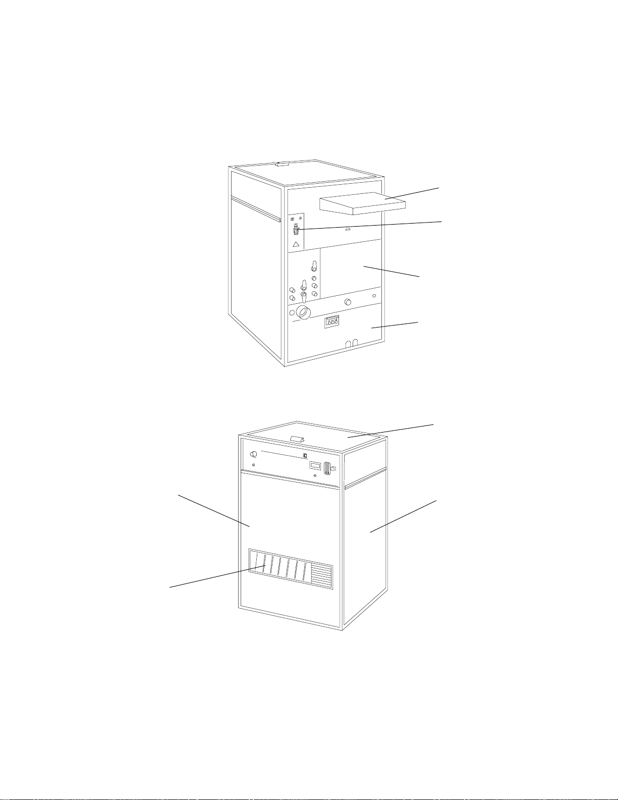
[10] Remove the RECEIVING-END ACCESS PANEL from the processor.
[11] Remove the 3 DRAIN HOSES from the RECEIVING BIN.
[12] Remove and keep the WRAPPED ITEMS from inside the front of the processor.
NOTE
On later models of the processor, some wrapped items may be found on top of the processor.
FEED-END MIDDLE
ACCESS PANEL
FEED-END LOWER
ACCESS PANEL
FEED TRAY
CONTROL
PANEL
RECEIVING-END
ACCESS PANEL
RECEIVING
BIN
Figure 4 Feed-End View of the Processor
TOP COVER
DRIVE SIDE
ACCESS PANEL
H048_0085BCA
H048_0085BA
H108_0003BCA
H048_0086BA
Figure 5 Receiving-End View of the Processor
10 246626
Page 11
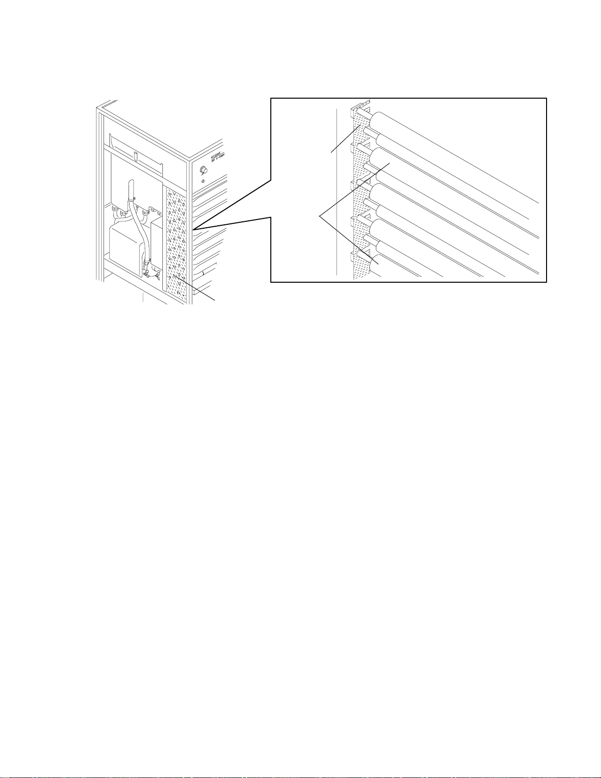
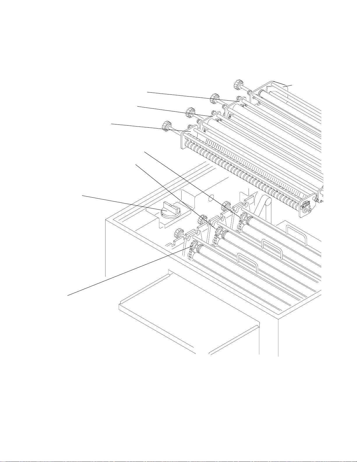
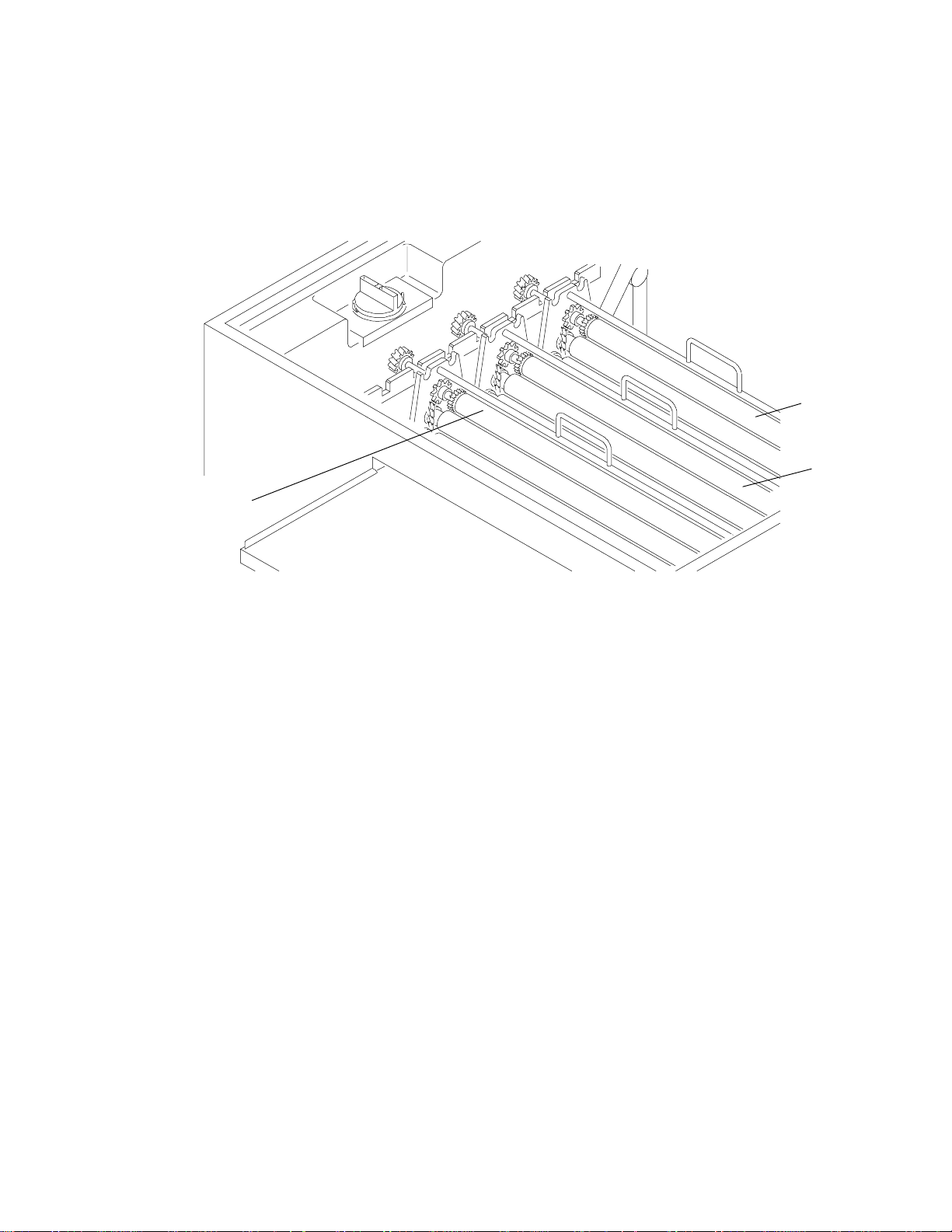
[13] Remove the 10 OUTER AIR TUBES and remove the PACKING MATERIAL around the SHAFTS of the
ROLLERS.
[14] Install the 10 OUTER DRYER AIR TUBES with the AIR SLOTS facing the film path.
PACKING
MATERIAL
DRYER
AIR
TUBES
CARDBOARD
Figure 6 Removing Cardboard from around the Roller Shafts
H048_0113BCA
H048_0113BA
246626 11
Page 12
Installing the Processor
H048_0108CA
PROCESSOR
H048_0108CCA
SKID
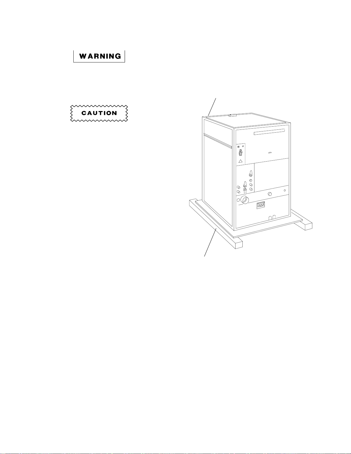
Removing the Processor from the Skid
The processor weighs over 200 kg
(442 lb), therefore use 2 people when
installing the LEVELING SCREWS and
moving the processor into position.
The processor is not attached to the
SKID. Use care when moving the
SKID.
[1] Move the processor, on the SKID, as close as
possible to the processor’s final destination.
Figure 7 Processor Mounted on Skid
12 246626
Page 13
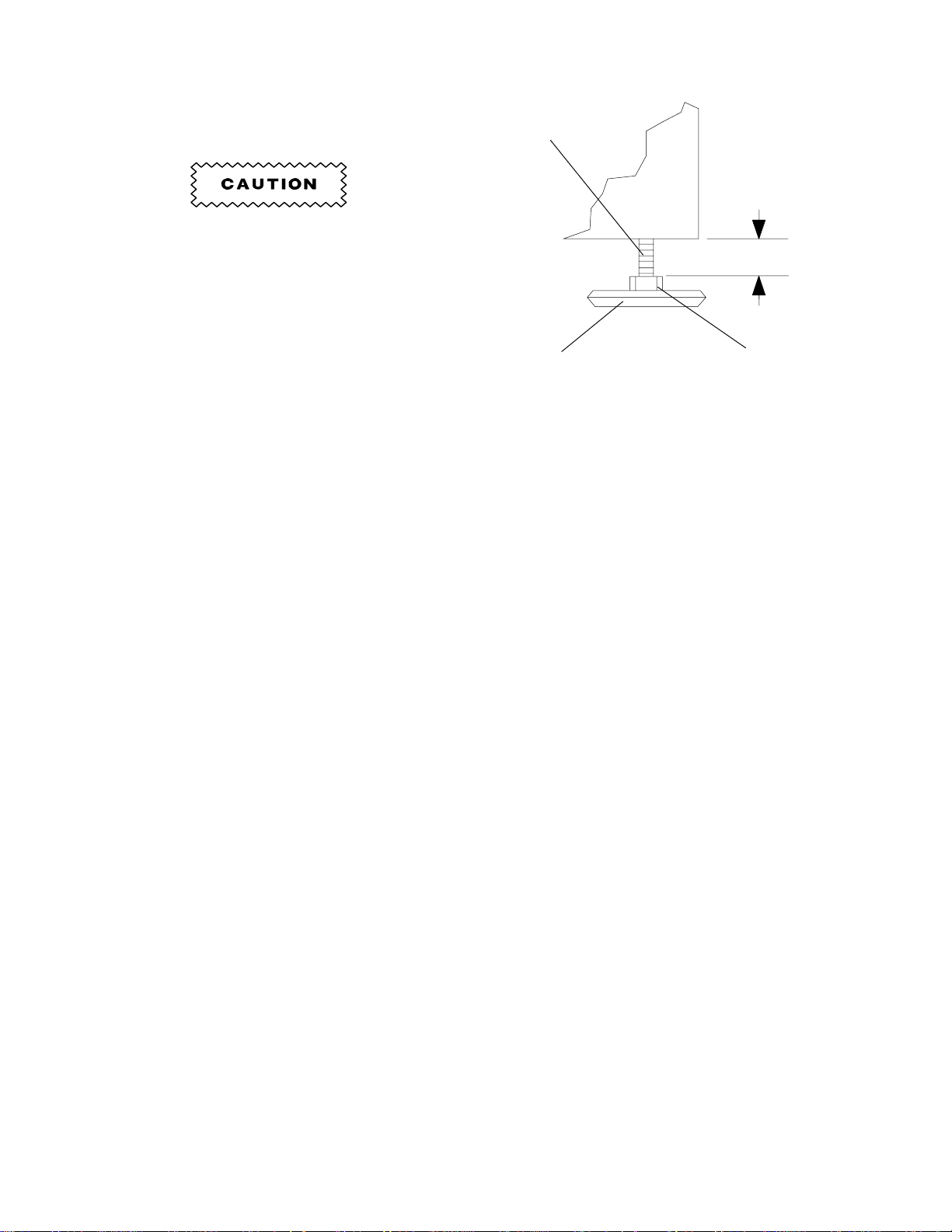
[2] Remove the FEED-END, LOWER ACCESS
H048_0141AC
2.5 cm (1 in.)
LEVELING
SCREW
FLOOR
PLATE
HEAD
H048_0141ACA
PANEL and the 2 SIDE PANELS from the
processor for easier access.
[3] Remove the processor from the SKID.
To prevent damage to the LEVELING
SCREWS and the processor, do not
allow more than a 25 mm (1 in.)
clearance between the bottom of the
processor and the HEAD of the
LEVELING SCREW.
[4] Install the 4 LEVELING SCREWS.
NOTE
For processors being used on 60 HZ
power, skip the next section on 50 Hz
Operation, and continue with the
section, ‘‘Installing the Light-Tight
Gasket’’ on page 17.
Figure 8 Installing the Leveling Screws
246626 13
Page 14
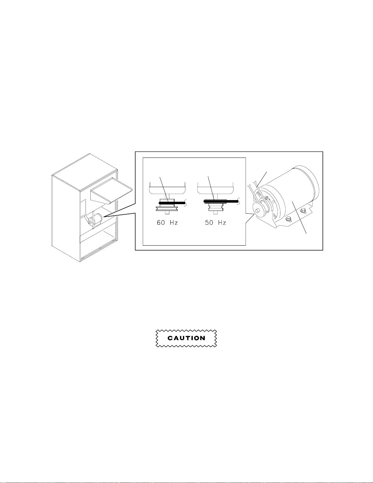
Setting a Processor for 50 Hz Operation
For processors being used on 50 Hz power, do the following:
[1] Remove the BLOWER MOTOR COVER.
[2] Move the BLOWER MOTOR to the inner set of mounting holes, located on the frame of the processor.
[3] Remove the BLOWER MOTOR PULLEY.
[4] Turn the BLOWER MOTOR PULLEY around and install the PULLEY making sure that the larger
diameter end of the PULLEY is mounted toward the BLOWER MOTOR MOUNTING FRAME. See
Figure 9.
[5] Move the DRIVE BELT to the larger diameter part of the BLOWER MOTOR PULLEY.
[6] Adjust the position of the BLOWER MOTOR to obtain the correct tension of the BLOWER DRIVE BELT.
See the Service Manual for the correct procedure.
SMALL
DIAMETER
LARGE
DIAMETER
DRIVE
BELT
BLOWER
MOTOR
H108_0015BCA
H108_0015BA
Figure 9 Positioning the Blower Motor and Drive Belt
[7] Check the alignment of the DRIVE BELT. Adjust the PULLEY as necessary. When the processor is
operating, check that this alignment is correct. See Figure 10 on page 15.
[8] Deenergize the processor by moving the MAIN CIRCUIT BREAKER, CB1, to the ‘‘O’’ position.
Do not place hands or fingers near the moving parts.
[9] Install the BLOWER MOTOR COVER.
14 246626
Page 15
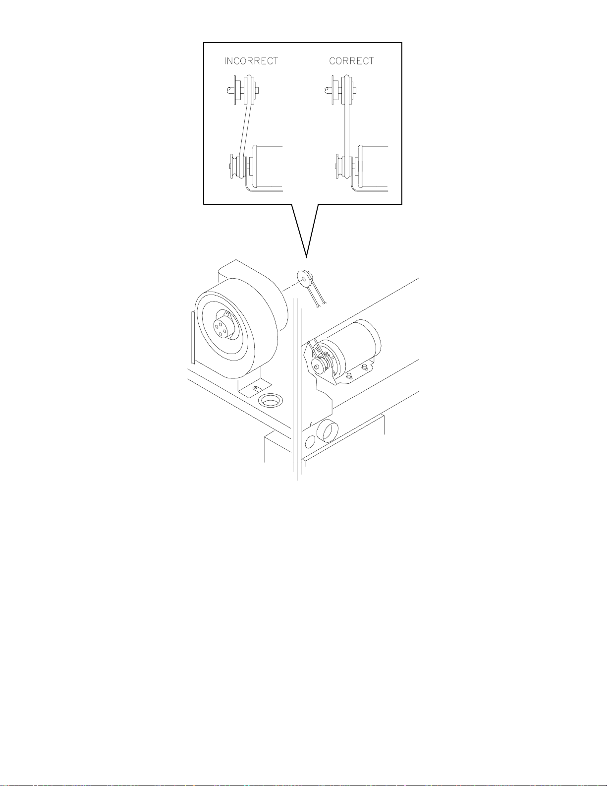
H048_0115CA
Figure 10 Aligning the Blower Motor Pulley
246626 15
Page 16

[10] Remove the SPLASH GUARD and the CHAIN GUARD from the MAIN DRIVE MOTOR.
[11] Loosen the MOTOR-MOUNTING BRACKET.
[12] Remove the CHAIN and the SPROCKET from the MAIN DRIVE MOTOR.
[13] Install from the prepack carton:
• Chain Segment
• 24-Tooth Sprocket
[14] Install the CHAIN.
[15] Move the MOTOR to adjust the CHAIN for the correct tension allowing a deflection of 3.2 to 6.4 mm
(1/8 - 1/4 in.).
CHAIN GUARD
MAIN DRIVE
MOTOR
MOTOR
SPROCKET
CHAIN
MOTOR MOUNT
BRACKET SCREW
H048_0114DCA
H048_0114DA
Figure 11 Exposing the Chain Drive
16 246626
Page 17

Installing the Light-Tight Gasket
H048_0107AA
H048_0107ACA
LIGHT-TIGHT
GASKET
(from Prepack)
LIGHT-TIGHT
GASKET
(INSTALLED)
[1] Install the LIGHT-TIGHT GASKET. See the
figure.
Do not stretch the GASKET.
Figure 12 Installing the Light-Tight Gasket
246626 17
Page 18

Installing the Feed Shelf
[1] Install the FEED SHELF using the 5 SCREWS, 5 WASHERS, and 5 LOCK WASHERS.
NOTE
Do not tighten the SCREWS.
WING NUT (3)
FEED SHELF
SCREW (5)
AUXILIARY
RUN SWITCH
CONNECTOR
RECEPTACLE
WASHER (5)
LOCK WASHER (5)
SCREW (5)
Figure 13 Installing the Feed Shelf
[2] Install the FILM GUIDE onto the FEED SHELF using the 3 WING NUTS and 3 WASHERS.
NOTE
Do not tighten the WING NUTS.
H048_0071BCC
H048_0071BA
[3] Plug the AUXILIARY/RUN SWITCH CONNECTOR into the RECEPTACLE.
18 246626
Page 19

Installing the Grommets and Replenisher Tubes
NOTE
For alternate installation of the
REPLENISHER TUBES, insert them
through the HOLES in the bottom of
the processor, see Figures 14 and 15,
or see the Site Specifications.
[1] Install the 2 GROMMETS. Remove a section
of the GROMMET if necessary.
[2] Install the REPLENISHER TUBES through the
GROMMETS.
SLOTS
SECTION
Figure 14 Alternate Method for
Installing Replenisher Tubes
H048_0006CA
GROMMETS
H108_0016CCA
H048_0109CA
Figure 15 Installing the Replenisher Tubes
Through the Processor Slots
246626 19
Page 20

Installing the Developer Filter
H108_0068AA
FILTER
CAP
DEVELOPER
FILTER
H108_0068ACA
[1] Install the DEVELOPER FILTER.
[2] Moisten the O-RING for the FILTER CAP with
water.
[3] Install the FILTER CAP.
Adjusting the Height of the Feed Shelf
Figure 16 Installing the Developer Filter
[1] Install the DEVELOPER RACK ASSEMBLY and the DETECTOR CROSSOVER ASSEMBLY, and check
that they are positioned correctly.
DEVELOPER/FIXER
CROSSOVER ASSEMBLY
FIXER/WASH
CROSSOVER
ASSEMBLY
SQUEEGEE
ASSEMBLY
ENTRANCE
DETECTOR
ASSEMBLY
H048_0097BCA
H048_0097BA
Figure 17 Installing the Detector Crossover Assembly
20 246626
Page 21

[2] Adjust the position of the FEED SHELF so
H108_0038AA
H108_0038ACB
5 SCREWS
NIP
ROLLERS
ENTRANCE
CROSSOVER
DETECTOR
3 WING NUTS
1 mm (1/16 in.)
Approximately
that it is approximately 1 mm (1/16 in.) lower
than the NIP of the DETECTOR
CROSSOVER ROLLERS.
[3] When the height is adjusted correctly, tighten
the 5 SCREWS.
NOTE
Do not tighten the WING NUTS.
Aligning the Film Guide
[1] Insert a 35 x 43 cm (14 x 17 in.) film.
Figure 18 Installing the Feed Shelf
[2] Use the edges of the film to align the FILM GUIDE with the DETECTOR CROSSOVER ASSEMBLY for
[3] Tighten the 3 WING NUTS.
SCREW (5)
squareness.
WING NUT (3)
FEED SHELF
FILM
GUIDE
Figure 19 Installing the Film Guide Assembly
DETECTOR
CROSSOVER
ASSEMBLY
H108_0034BCA
H108_0034BA
246626 21
Page 22

Moving the Processor Into Position
H108_0030AA
PROCESSOR
WALL
H108_0030ACA
H048_0141AC
2.5 cm (1 in.)
LEVELING
SCREW
FLOOR
PLATE
HEAD
H048_0141ACA
The processor weighs over 200 kg
(442 lb), therefore use 2 people when
installing the LEVELING SCREWS and
moving the processor into position.
[1] Move the processor within approximately
2.5 cm (1 in.) of the wall.
[2] Install the FLOOR PLATES.
[3] Move the processor against the wall.
[4] Check that the LIGHT-TIGHT GASKET is tight
against the wall. Compress the LIGHT-TIGHT
GASKET to approximately 10 mm (3/8 in.).
Figure 20 Positioning the Processor
22 246626
Figure 21 Installing the Floor Plates
Page 23

Leveling the Processor
To prevent damaging the LEVELING SCREWS and the processor, do not allow more than a
25 mm (1 in.) clearance between the bottom of the processor and the HEAD of the LEVELING
SCREW.
[1] Install and seat the DEVELOPER, FIXER, and WASH RACK ASSEMBLIES.
DEVELOPER
RACK
WASH
RACK
FIXER
RACK
H048_0096BCA
H048_0096BA
Figure 22 Installing the Rack Assemblies
[2] Check that the RACKS are in their correct positions and that the GEARS of the RACK ASSEMBLIES
engage with the GEARS of the MAIN DRIVE SHAFT.
RACK
ASSEMBLY
GEAR
MAIN
DRIVE
SHAFT
GEAR
H108_0063BCA
H048_0101BA
Figure 23 Positioning the Racks and Gears
246626 23
Page 24

The edge of the LEVEL could cause damage to the surface of the ROLLER.
[3] Place a LEVEL as shown in the figure. Adjust the LEVELING SCREWS to level the processor from side
to side.
LEVEL
H048_0102BCA
H048_0102BA
Figure 24 Leveling the Processor Side to Side
[4] Place a LEVEL as shown in the figure. Adjust the LEVELING SCREWS to level the processor from front
to back.
LEVEL
ROLLERS
H108_0058BCA
H108_0058BA
Figure 25 Leveling the Processor Front to Back
24 246626
Page 25

[5] Install the Seismic Kit, if required.
LEVELING
SCREW (4)
LEVELING SCREW (4)
WASHER (8)
FLOOR PLATE (4)
SLOT
BRACKET (4)
Figure 26 Installing the Seismic Kit
BOLT (8)
H108_0193DCA
H108_0193DA
246626 25
Page 26

Connecting the Replenishment Tanks
[1] Install the STRAINERS.
[2] Connect the 10 mm (3/8 in.) TUBING (not supplied) from the inlets of the REPLENISHMENT PUMP
ASSEMBLY to the DEVELOPER and FIXER REPLENISHMENT TANKS.
To prevent contamination of the processor solutions, check that the DEVELOPER and FIXER
REPLENISHMENT TUBES are connected to the correct tanks.
REPLENISHMENT
REPLENISHMENT
TANKS
PUMP ASSEMBLY
STRAINERS
Figure 27 Connecting Replenishment Tubing
H048_0110BCA
H048_0110BA
26 246626
Page 27

Connecting the Drains
H048_0112CA
WASH
DRAIN
VALVE
WASH
OVERFLOW/DRAIN
FIXER
OVERFLOW/DRAIN
DEVELOPER
OVERFLOW/DRAIN
WATER
INLET
DEVELOPER
DRAIN
VALVE
DEVELOPER
AUXILIARY
DRAIN
FIXER
AUXILIARY
DRAIN
FIXER
DRAIN
VALVE
H048_0112CCA
The processor is equipped to accommodate the
separation of DEVELOPER, FIXER, and WATER
effluent liquid. The processor is shipped from the
factory with a separate FIXER OVERFLOW/TANK
DRAIN, AUXILIARY FIXER TANK DRAIN,
DEVELOPER OVERFLOW/TANK DRAIN,
AUXILIARY DEVELOPER TANK DRAIN, and a
common WASH WATER OVERFLOW/TANK DRAIN.
To prevent severe corrosion, do not
use brass or copper piping.
[1] Connect the three 1.9 cm ( ⁄
3
in.) tubes
4
provided, on the FEED-END of the processor.
Route the tubing as required. Drain service
must comply with local codes. Do not make a
solid connection at the floor drain.
Figure 28 Connecting the Drains
246626 27
Page 28

Connecting the Wiring to Terminal Strip TB1
[1] Remove the LOWER ACCESS PANEL from the FEED-END of the processor.
[2] Open the TRANSFORMER BOX DOOR.
[3] Determine the supply voltage being applied to the processor.
[4] Connect the main input power wires to TERMINAL STRIP TB1.
[5] Take the appropriate ELECTRIC SERVICE LABEL from the PREPACK CARTON. Install the ELECTRIC
SERVICE LABEL on the DATA PLATE which is located on the REPLENISHER CHECK TUBE
BRACKET.
[6] Connect the JUMPERS from the PREPACK CARTON to TERMINAL STRIP TB2. See the figure.
[7] Dress the JUMPER wires neatly to prevent damage to the wires due to pinching or scraping by the panel
edge.
[8] Close the TRANSFORMER BOX DOOR.
TERMINAL
STRIP TB1
TRANSFORMER
BOX DOOR
TERMINAL
STRIP TB2
H048_0083DCC
H048_0083DA
Figure 29 Accessing Terminal Strip TB1 and Installing the Electric Service Label
28 246626
Page 29

BUILDING
POWER SYSTEM
3 Phase Neutral
120V.L-N/208V.L-L
127V.L-N/220V.L-L
3 WIRE
OR
L1
N
L2
NOMINAL SUPPLY
VOLTAGE
120/208
MEASURED SUPPLY
VOLTAGE
104/180-127/220
FREQUENCY
(Hz)
60
CONNECTION
DIAGRAM
A
L3
1
PROCESSOR
1
PROCESSOR
Single Phase Neutral
100V.L-N/200V.L-L
120V.L-N/240V.L-L
23
TB1
220V.L-L
OR
240V.L-L
L1
32
TB1
3 WIRE
OR
L1
4
2 WIRESingle Phase
L2
4
N
127/220
220
240
120/200
115/199-123/213
124/215-140/242
198-216
217-242
226-254
90-98
99-110
50
50
50/60
50/60
B
C
D
E
F
G
H
L2
1
23
TB1
PROCESSOR
3 Phase Neutral
220V.L-N/380V.L-L
OR
240V.L-N/415V.L-L
L1
L3
1
TB1
PROCESSOR
(LOAD SPLITTING)
4
4 WIRE
120/240
230/380
104/208-127/254
207/357-233/403
60
50
SPLIT LOAD
N
L2
4
32
240/415
225/390-254/440
50
SPLIT LOAD
J
K
L
H108_9020EC
Figure 30 Wiring Diagrams
246626 29
Page 30

TB2
A
TB2
B
TB2
C
N
12
4
3
5
H1
H2
H3
H5
H4
X1
X2
X3
X4
7
30
ADD WIRE JUMPERS: 12 TO 4 ADD WIRE JUMPERS: N TO H1
SOLS., SF.
LT. 120V
DEV. HTR.
DRY
240V
MTRS. ETC.
4 TO H4
5 TO H1
X4 TO 7
240V
HTRS.
T1
NN
12
4
3
5
H1
H2
H3
H5
H4
X1
X2
X3
X4
7
30
REMOVE METAL STRAP H2-H3
SOLS., SF.
LT. 120V
DRY
HTRS.
240V
T1
D
DEV. HTR.
MTRS. ETC.
240V
H1 TO H3
12 TO 4
4 TO H2
H2 TO H4
X3 TO 7
SOLS., SF.
12
4
3
5
H1
H2
H3
H5
H4
X1
X2
X3
X4
T1
7
30
REMOVE METAL STRAP H2-H3
ADD WIRE JUMPERS: N TO H1
E
LT. 120V
DRY
HTRS.
240V
H1 TO H3
12 TO H2
H2 TO H4
4 TO X2
X2 TO 7
DEV. HTR.
MTRS. ETC.
240V
F
TB2
NN
12
4
3
5
H1
H2
H3
H5
H4
X1
X2
X3
X4
T1
7
30
ADD WIRE JUMPERS: N TO 3
SOLS., SF.
LT. 120V
DRY
HTRS.
240V
3 TO H1
12 TO H5
4 TO H4
X3 TO 7
DEV. HTR.
MTRS. ETC.
240V
TB2
SOLS., SF.
12
4
3
5
H1
H2
H3
H5
H4
X1
X2
X3
X4
T1
7
30
ADD WIRE JUMPERS: N TO 3
LT. 120V
DRY
HTRS.
240V
3 TO H1
12 TO H2
4 TO H4
H4 TO 7 X1 TO 7
DEV. HTR.
MTRS. ETC.
240V
TB2
N
12
4
3
5
H1
H2
H3
H5
H4
X1
X2
X3
X4
7
30
ADD WIRE JUMPERS: N TO 3
SOLS., SF.
LT. 120V
DRY
HTRS.
240V
T1
3 TO H1
12 TO H2
4 TO X2
DEV. HTR.
MTRS. ETC.
240V
H108_9021EC
Figure 31 Wiring Diagrams (Cont.)
30 246626
Page 31

TB2
G
TB2
H
J
TB2
N
12
4
3
5
H1
H2
H3
H5
H4
X1
X2
X3
X4
7
30
REMOVE METAL STRAP H2-H3
ADD WIRE JUMPERS: N TO H1
SOLS., SF.
LT. 120V
DRY
HTRS.
240V
T1
DEV. HTR.
MTRS. ETC.
H1 TO H3
12 TO X4
X4 TO 7
4 TO H2
H2 TO H4
240V
NN
12
4
3
5
H1
H2
H3
H5
H4
X1
X2
X3
X4
7
30
REMOVE METAL STRAP H2-H3
ADD WIRE JUMPERS: N TO H1
K
SOLS., SF.
LT. 120V
DEV. HTR.
DRY
240V
MTRS. ETC.
240V
H1 TO H3
12 TO X3
X3 TO 7
4 TO H2
H2 TO H4
HTRS.
T1
12
4
3
5
H1
H2
H3
H5
H4
X1
X2
X3
X4
7
30
ADD WIRE JUMPERS: 12 TO 4
SOLS., SF.
LT. 120V
DEV. HTR.
DRY
240V
4 TO 7
MTRS. ETC.
240V
HTRS.
T1
L
TB2
NN
12
4
3
5
H1
H2
H3
H5
H4
X1
X2
X3
X4
T1
7
30
REMOVE METAL STRAP 3-5 REMOVE METAL STRAP 3-5
ADD WIRE JUMPERS: N TO H1
SOLS., SF.
LT. 120V
DRY
HTRS.
240V
H1 TO 7
12 TO H5
4 TO 3
3 TO 3
3 TO X2
DEV. HTR.
MTRS. ETC.
240V
TB2
SOLS., SF.
12
4
3
5
H1
H2
H3
H5
H4
X1
X2
X3
X4
T1
7
30
ADD WIRE JUMPERS: N TO H1
LT. 120V
DRY
HTRS.
240V
H1 TO 7
12 TO H2
4 TO X2
3 TO H4
DEV. HTR.
MTRS. ETC.
240V
H108_9022EC
Figure 32 Wiring Diagrams (Cont.)
246626 31
Page 32

Connecting the Exhaust
[1] Connect 7.6 cm (3 in.) ELBOWS and rigid DUCT or flexible EXHAUST HOSE between the processor
EXHAUST PORT and the BUILDING EXHAUST DUCT.
NOTE
Do not make a solid connection at the BUILDING END. Do not connect the EXHAUST DUCT to
the processor at this time.
[2] Measure the static pressure in the DUCT using a modified J TUBE (CHECK TUBE 592380) and AIR
METER TL-2431. Make the measurement 30.5 cm (12 in.) from the end of the DUCT to be connected
to the processor.
AIR FLOW
30 cm
(12 in.)
AIR METER
EXHAUST HOSE
Figure 33 Measuring the Static Pressure
RUBBER HOSE or
MODIFIED J TUBE
TAPE (3 places)
HOSE SUPPORT
CENTER CONNECTOR
H048_0118BCA
H048_0118BA
32 246626
Page 33

[3] To obtain the correct static pressure, as shown in Table 1, adjust the clearance at the BUILDING END of
the DUCT as illustrated.
Table 1 Static Pressures
Negative Static Pressure, (Water Head)
Duct Diameter MIN MAX
76 mm (3 in.) 0.76 mm (0.03 in.) 1.02 mm (0.04 in.)
102 mm (4 in.) 0.25 mm (0.01 in.) 0.51 mm (0.02 in.)
[4] Connect the DUCT to the building exhaust.
Adjust clearance to obtain
required static pressure in duct.
Adjust clearance to obtain
Do not make solid connection.
required static pressure in duct.
Duct
from
Processor
Do not make solid connection.
5.1 cm (2.0 in.)
maximum
Figure 34 Connecting the Processor Exhaust to the Building Exhaust
[5] Connect the DUCT to the processor.
H108_0008BAA
H108_0008BA
246626 33
Page 34

Making the Water Connection
Before connecting the water line to the processor, flush the line to remove any debris or rust
particles in the line.
See the Site Specifications, and install the plumbing to the water connection, using an adapter if necessary.
Checking the Drain Valves
Check that the 3 DRAIN VALVES are closed. All VALVE HANDLES should be in the vertical position.
CHECK
VALVE
MIXING
VALVE
SHUTOFF
VALVES
COLD WATER
SUPPLY
CIRCUIT
BREAKER
COLD WATER
SUPPLY
HOT WATER
SUPPLY
H048_0089DCA
H048_0089DA
Figure 35 Connecting the Water Inlet Plumbing
34 246626
Page 35

User Selectable Modes
Flooded Replenishment
Factory set to ‘‘OFF’’ (Left) position.
This feature is designed for low film usage. When in the ‘‘ON’’ (Right) position, it allows for replenishment of
the developer and fixer solutions each time the processor comes out of standby.
Water Conservation
Factory set to ‘‘ON’’ (Right) position.
[1] When water conservation is ‘‘ON’’, and the processor cycles into standby, no water flows to the
processor except when water is needed for developer cooling. As film is processed, water flows into the
wash tank.
NOTE
When the processor is not in use, it will continue to cycle in and out of standby without water
flowing to the wash tank.
[2] When water conservation is ‘‘OFF’’, water continually flows to the wash tank as long as the processor is
out of standby.
246626 35
Page 36

Selecting the Replenishment Mode
[1] To access SWITCH U20 on the 100 CIRCUIT BOARD, open the ELECTRICAL BOX DOOR.
[2] If the customer requires FLOODED REPLENISHMENT, set the SWITCH U20-1 to the right (ON).
[3] If the customer requires no WATER CONSERVATION, set the SWITCH U20-2 to the left (OFF).
[4] U20-3 must be set to the right (ON) position.
[5] U20-4 must be set to the left (OFF) position.
ELECTRICAL
BOX DOOR
100 CIRCUIT BOARD
U20
SWITCHES
Figure 36 Setting Switch U20 on the 100 Circuit Board
H048_0099DCA
H048_0099DA
36 246626
Page 37

Using the Splash Guard and Drip Tray
[1] Install a SPLASH GUARD before removing or installing a RACK ASSEMBLY.
[2] Set the RACK ASSEMBLY into the DRIP TRAY.
SPLASH
GUARD
DRIP
TRAY
H048_0119BCA
H048_0119BA
Figure 37 Installing the Splash Guard
Filling the Tanks
• Before filling the tanks with chemicals, it is recommended that you fill the tanks with water and
check the plumbing system for leakage with the processor energized.
• All adjustable metal band clamps used on tubing connections must be checked for tightness at the
time of the processor installation.
• Although a clamp may be properly tightened at the time of installation, cold-flow (shrinkage) of the
plastic tubing will take place beneath the clamp, thus the clamp may require further tightening within 2
to 4 weeks.
• Always check the tightness of the clamp after installing replacement tubing.
[1] Remove all the RACKS.
[2] Install the SPLASH GUARD. See Figure 37.
NOTE
246626 37
Page 38

[3] Fill the FIXER TANK to the FIXER FILL LINE. See the figure.
DRIVE
SIDE
NON-DRIVE
SIDE
FIXER
FILL LINE
DEVELOPER
FILL LINE
H048_0094BCA
H048_0094BA
Figure 38 Tank Fill Lines
[4] Clean any FIXER spills.
[5] Clean the SPLASH GUARD.
[6] Install the SPLASH GUARD to allow filling of the DEVELOPER TANK.
[7] Fill the DEVELOPER TANK to the DEVELOPER FILL LINE.
[8] Open the WATER SUPPLY VALVE to provide water to the processor. (The tank will not fill until the
processor is energized in a later step.)
38 246626
Page 39

[9] Unlock the DRYER TEMPERATURE CONTROL KNOB by rotating the LOCKING RING
counter-clockwise approximately ⁄
1
turn.
4
[10] Rotate the DRYER TEMPERATURE CONTROL KNOB counter-clockwise as far as it will turn.
[11] Lock the DRYER TEMPERATURE CONTROL KNOB by rotating the LOCKING RING clockwise
approximately ⁄
1
4
turn.
NOTE
This will keep the DRYER at minimum heat to provide the correct temperature for adjusting the
tension of the DRYER BELT.
LOCKING
RING
SETSCREW
DRYER TEMPERATURE
CONTROL KNOB
REPL
SWITCH
H048_0105BCA
H048_0105BA
Figure 39 Adjusting the Dryer Temperature Control Knob
246626 39
Page 40

If the processor is to be operated at
H048_0106CA
CIRCUIT
BREAKER
H048_0106CCA
50 Hz, make sure that the processor is
set for operation at 50 Hz. See the
procedure ‘‘Setting a Processor for
50 Hz Operation’’ on page 14.
[12] Move the CIRCUIT BREAKER to the ‘‘I’’, or
energized position
[13] Check that the RECIRCULATION PUMPS are
operating by observing motion on the surface
of the solution TANKS.
[14] Allow the wash water to overflow for
5 minutes or longer.
[15] Clean the WASH TANK, if necessary.
[16] Check the processor for leaks.
IMPORTANT
After the processor has been in regular
use for one or 2 days, once again
check the processor for leaks.
Figure 40 Control Panel of the Processor
40 246626
Page 41

Setting the Replenishment Rates
NOTE
Refer to the manufacturer’s specifications for the film and chemicals being used, for operating
temperatures and replenishment rates. The KODAK
No. 30 is available from your Kodak Representative or Marketing Technical Group, Health
Sciences Division, Eastman Kodak Company, Rochester, New York 14650.
NOTE
Contact a qualified operator, service personnel, or authorized dealer representative to perform the
following adjustments.
[1] Remove the RECEIVING-END ACCESS PANEL and the DRIVE SIDE ACCESS PANEL from the
processor. Run the REPLENISHMENT PUMP to purge air from the system.
[2] With the 2 GRADUATED CYLINDERS under the REPLENISHMENT CHECK TUBES, turn the VALVES
on and press the ‘‘REPL’’ SWITCH. See Figure 39 on page 39, if necessary. Run the PUMP to purge
air from the system.
[3] With the GRADUATED CYLINDER under the DEVELOPER CHECK TUBE, turn the VALVE on and
press the ‘‘REPL’’ SWITCH for 13 seconds.
NOTE
RP
X-OMAT Processor Service Bulletin
This is the amount of time film, 14 inches in length, causes the replenishment pump to operate.
[4] Compare the average of 2 or more measurements with the film and chemical specifications of the
manufacturer.
[5] If necessary, adjust the developer replenishment rate following the instructions on page 42.
[6] Repeat for FIXER REPLENISHMENT rate.
246626 41
Page 42

Adjusting the Replenishment Rate
Do not adjust the SETSCREW or LOCK NUT.
[1] Remove the outside PUMP COVER by loosening the 2 SCREWS on the top of the PUMP, and lifting the
COVER off.
[2] Rotate the CRANK by hand to gain access to the ADJUSTING SCREW.
[3] Rotate the appropriate fixer or developer ADJUSTING SCREW to provide the correct replenishment
rates.
[4] Install the PUMP COVER.
CRANK
ADJUSTING SCREW
OUTPUT
DECREASE
INCREASE
STROKE INDICATOR
STROKE SCALE
SET SCREW
(DO NOT ADJUST)
SCREW (2)
PUMP
COVER
Figure 41 Setting the Replenishment Rate
H048_0104BCA
H048_0104BA
42 246626
Page 43

Installing the Racks and Crossovers
[1] Carefully, install the RACKS. Use the SPLASH GUARD.
[2] Install the CROSSOVERS.
FILTER
CANISTER
ASSEMBLY
FIXER/WASH
CROSSOVER
DEVELOPER/FIXER
CROSSOVER
DETECTOR
CROSSOVER
FIXER
RACK
SQUEEGEE
ASSEMBLY
WASH
RACK
DEVELOPER
RACK
H048_0092DCA
H048_0092DA
Figure 42 Installing the Racks and Crossovers
246626 43
Page 44

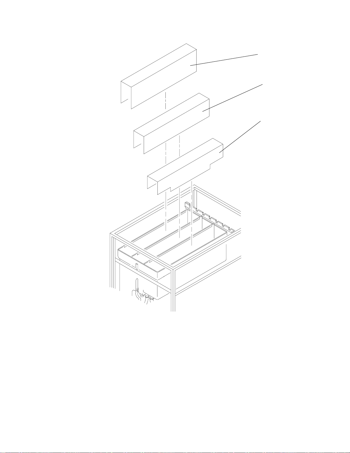
[3] Install the EVAPORATION COVERS.
Figure 43 Installing the Evaporation Cover
EVAPORATION
COVERS
H048_0103BCA
H048_0103BA
44 246626
Page 45

Adjusting the Tension of the Dryer Belt
Parts are moving within the processor. Keep hands and loose clothing out of the processor.
[1] With the processor operating, the DRYER TEMPERATURE CONTROL rotated to the full
counter-clockwise position, and the dryer cool, adjust the tension of the DRYER BELT as follows:
[2] Loosen the LOCKING SCREW.
[3] Rotate the ADJUSTING SCREW KNOB to tighten the BELT until the ROLLERS just begin to rotate.
[4] Rotate the ADJUSTING SCREW KNOB an additional 1 rotation.
[5] Tighten the LOCKING SCREW.
[6] Tighten the ADJUSTING SCREW LOCK NUT.
BELT
AIR
TUBE
LOCKING
SCREW
ADJUSTING
SCREW LOCKNUT
ADJUSTING
ROLLER
SCREW KNOB
ASSEMBLY
Figure 44 Locating the Dryer Belt and Adjuster
H048_0093BCA
H048_0093BA
246626 45
Page 46

Installing the Panels and Covers
Install all PANELS and COVERS.
When required by local code, install panel-locking devices. Parts and instructions are included in
the PREPACK.
Setting the Dryer Temperature
NOTE
[1] Unlock the DRYER TEMPERATURE CONTROL KNOB by rotating the LOCKING RING
counter-clockwise approximately ⁄
1
turn.
4
[2] Set the DRYER TEMPERATURE CONTROL KNOB to the minimum setting required to dry film.
[3] Lock the DRYER TEMPERATURE CONTROL KNOB by rotating the LOCKING RING clockwise
approximately ⁄
1
4
turn.
LOCKING
RING
SETSCREW
DRYER TEMPERATURE
CONTROL KNOB
H048_0105BCA
H048_0105BA
REPL
SWITCH
Figure 45 Adjusting the Dryer Temperature Control Knob
46 246626
Page 47

Checking the Developer Temperature
[1] When the DEVELOPER LAMP begins to flash, remove the TOP COVER.
[2] Insert a THERMOMETER of known accuracy into the DEVELOPER TANK.
[3] Install the TOP COVER.
[4] Operate the processor for 15 minutes to stabilize the temperature.
[5] Check that the temperature on the DEVELOPER TEMPERATURE METER is the same as on the
THERMOMETER (35°C [95°F] set at the factory).
NOTE
See the Service Manual for the adjustment procedure.
THERMOMETER
H048_0098BCA
H048_0098BA
Figure 46 Placing the Thermometer
[6] Check that the following are installed:
• RACKS
• CROSSOVERS
• COVERS
[7] Check that the LIGHT-TIGHT GASKET is tight against the wall.
Checking the Film Transport
[1] Feed three 35 x 43 cm (14 x 17 in.) films into the processor. Check that the RACKS move the film
through the processor correctly.
246626 47
Page 48

3040ii_a.txt
EASTMAN KODAK COMPANY • ROCHESTER, N.Y. 14650Printed in USA
Kodak
and
X-Omat
are trademarks.
Customer Equipment Services Division
 Loading...