

Page 1
Installation and Setup Manual Publication No II 3478
4/99
Supersedes 7/97
KODAK
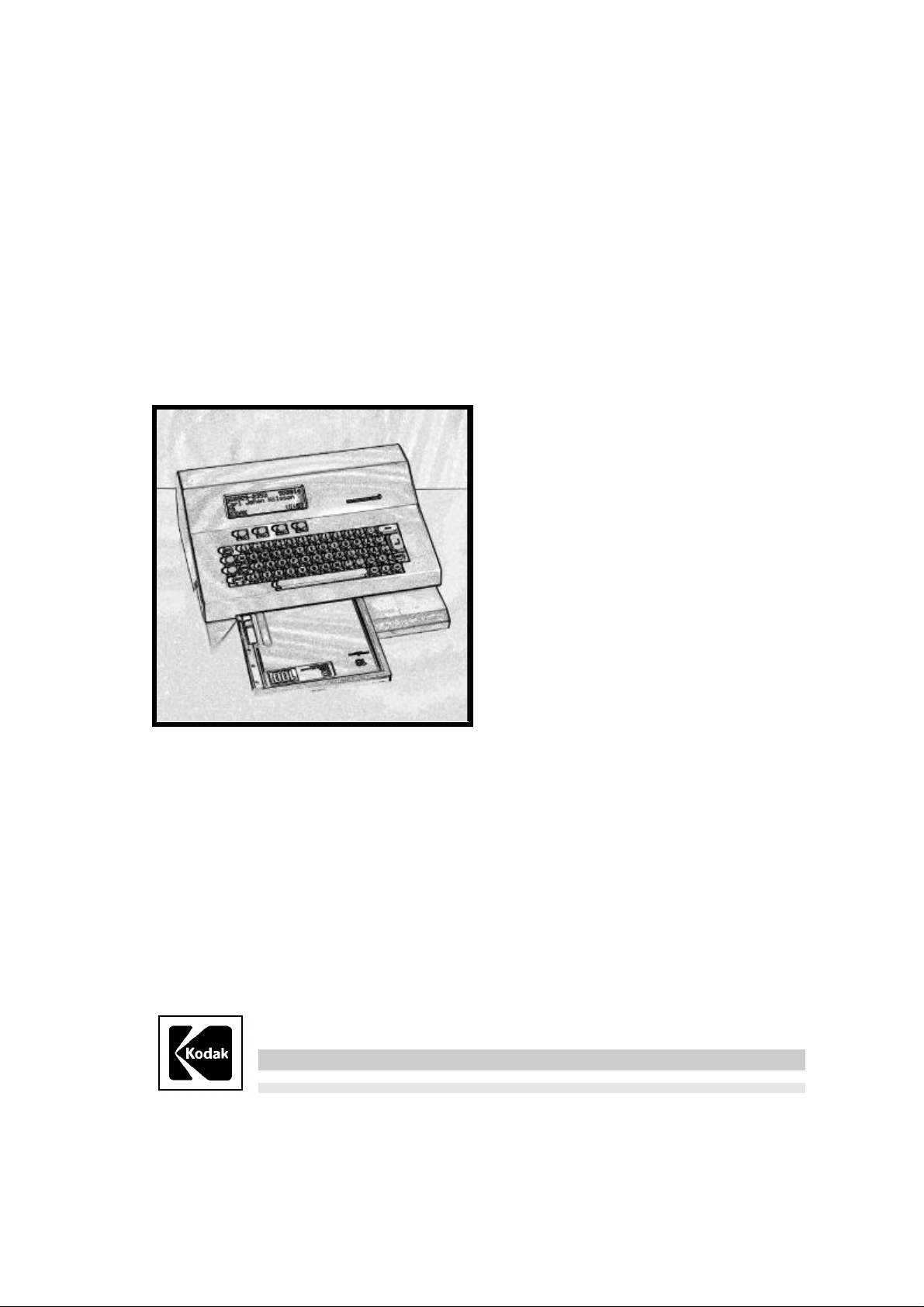
Network ID Camera
Health Imaging
Page 2

Page 3
PLEASE NOTE
The information contained herein is based on the experience and knowledge relating to the
subject matter gained by Kodak prior to publication.
No patent license is granted by this information.
Kodak reserves the right to change this information without notice, and makes no warranty,
expressed or implied, with respect to this information. Kodak shall not be liable for any loss or
damage, including consequential or special damages, resulting from the use of this
information, even if loss or damage is caused by Kodak’s negligence or other fault.
MM CAUTION MM
This manual shall be used only by service personnel
This equipment includes parts and assemblies sensitive to damage from electrostatic
discharge. Use caution to prevent damage during all service procedures.
Page 4

Page 5

II 3478 Installation and Set-up Manual
Table of Contents
Description Page
1 General 1
2 Installation 1
2.1 Unpacking.................................................................................................................................... 1
2.2 Installation Details....................................................................................................................... 1
3 Setup 3
3.1 Getting into setup mode............................................................................................................. 3
3.2 Resetting to factory default........................................................................................................ 3
3.3 Main configuration window........................................................................................................ 4
3.3.1 Picture and settings................................................................................................................ 4
3.3.2 Communication param ........................................................................................................... 4
3.3.3 Settings.................................................................................................................................. 4
3.3.4 Sensor adjustment .................................................................................................................. 5
3.3.5 Test functions......................................................................................................................... 5
3.3.6 Serial analyzer........................................................................................................................ 5
3.3.7 Remote control....................................................................................................................... 5
3.3.8 System logger ........................................................................................................................ 5
3.4 Pictures and settings ................................................................................................................ 5
3.4.1 Picture....................................................................................................................................5
3.4.2 Some frequently used words................................................................................................... 6
3.4.3 Picture Standard, C1/Min-R2, C1N......................................................................................... 6
3.4.4 Editing a field.......................................................................................................................... 7
3.4.5 Settings Standard, C1/Min-R2, C1N........................................................................................ 8
3.4.6 Menues................................................................................................................................... 9
3.5 Communication param.............................................................................................................. 10
3.5.1 Communication parameters Channel: HOST........................................................................ 11
3.5.2 Protocol set-up ..................................................................................................................... 12
3.5.3 Communication parameters Channel: AUX ........................................................................... 12
3.5.4 Protocol set-up SIEMENS Mammomat
3.5.5 Protocol set-up GE Medical System Senographe.................................................................. 15
3.5.6 Protocol set-up GXDP........................................................................................................... 16
®
3000 ....................................................................... 13
3.6 Settings...................................................................................................................................... 18
3.7 Remote control.......................................................................................................................... 19
3.7.1 Save a Set-up....................................................................................................................... 19
3.7.2 Load a Set-up....................................................................................................................... 20
Kodak AG Stuttgart 4/99
i
Page 6

Installation and Set-up Manual II 3478
4 Upgrading the firmware 21
4.1 Download the firmware..............................................................................................................21
5 Error Messages 23
5.1 Illegal value.................................................................................................................................23
5.2 The adjustment may be max 32.................................................................................................23
5.3 Out of storage for FTEXT ..........................................................................................................23
5.4 Length must be between 1 and 8..............................................................................................23
5.5 Communication error.................................................................................................................23
5.6 Programming voltage missing (JP8).........................................................................................24
5.7 Failed to erase set-up memory..................................................................................................24
5.8 Failed to program set-up memory .............................................................................................24
5.9 Unknown programming error....................................................................................................24
4/99 Kodak AG Stuttgart
ii
Page 7

II 3478 Installation and Set-up Manual
1 General
This manual describes how to install and setup the KODAK Network ID Camera herein
called KNIC. This includes anything from installation to setting-up what the picture printed
on the film should look like, which language for the display, to how it should communicate
with a booking system.
This manual is written for software version 2.1 and it is assumed that language is set to
English. Note that you may select language to English which causes all texts to be
displayed in English, but still select country to the country you are in to get countrydependent information, like date format and PID number, correct.
2 Installation
2.1 Unpacking
Check that the cardboard box is undamaged and has no holes or deep scratches. Any
damage must be reported to the transport company or the supplier whenever it can be
suspected that the camera has been damaged during transport.
The box contains the camera, an operator’s manual in local language and the power
cord. The keyboard should be equipped with the country dependent keycaps. If the
power cord and the country dependent keycaps are not packed with the camera, they are
delivered in a separate box.
2.2 Installation Details
After unpacking the camera it should be placed on a steady table or shelf. If the camera
is operated in mobile units like mammography screening buses, or where there is a risk of
the camera falling down, it should be fastened to the surface with two screws mounted
from the inside of the camera through two holes in the bottom plate with suitable screws.
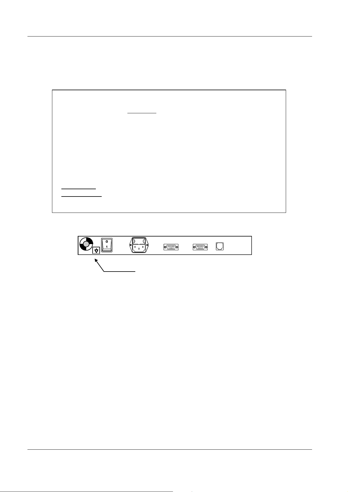
The power cord should be connected to the power receptacle on the backside of the
camera and to wall outlet.
No voltage selection is necessary, the camera can be operated at any nominal
voltage from 220 VAC to 240 VAC.
Power receptacle
Kodak AG Stuttgart 4/99
1
Page 8
Installation and Set-up Manual II 3478
Check with customer that the keyboard has the local used keycaps.
Country keycap sets can be ordered as spare parts if needed.
Caution
The KODAK Network ID Camera is classified as Information Technology
Equipment according to EN 60950.
According to European Safety Regulations for Medical Equipments, the
following conditions must be fullfilled:
- if the camera is operated within a distance of 1.5 m from the patient, it must
be connected to the equipotential equalization device (E2D).
E2D with cable must be provided by the customer.
The purpose of the E2D is to ensure that all medical and other equipments
are connected to the same ground potential.
- if the camera is connected to a Medical Equipment according to
EN 60601-1( e.g. safety ground or data connections) the safety standard
EN 60601-1-1 has to be met and documented.
E2D plug - Connector for the cable
comming from the equipotential bushbar.
4/99 Kodak AG Stuttgart
2
Page 9

II 3478 Installation and Set-up Manual
3 Setup
This section describes how the set-up of the camera is done. It assumes that the operator
is familiar with the camera.
3.1 Getting into setup mode.
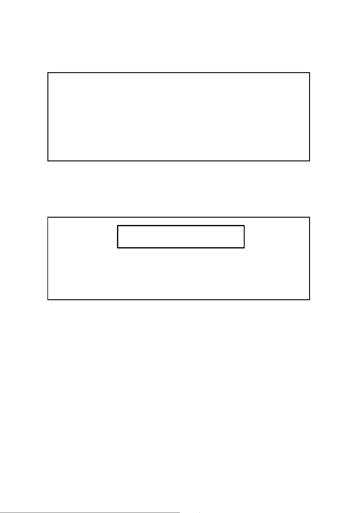
Make sure the camera displays the main window which is the window that comes up after
the initial screen with the Kodak and Triacon logo. The window shows:
Date: 031197 Time:15:45:48
Selected cassette : Standard, C1
Manual Booking Memory Cass type
To get into setup mode now, press Shift F4 (the right soft-key while holding any of the
two shift keys down). A new window will appear asking for a password.
Two passwords are available where one does not give access to all parameters.
The first password LANEX is intended for Kodak personnel. It gives access to all settings.
The other password KELP is intented for Key Operator and will only allow to change the
picture and communication set-up.
Use password LANEX .
Do not give any of these two passwords to the customer.
The KODAK Network ID Camera will remember the password for about 15 minutes and
will not ask you for the password again, if you exit and then enter set-up mode again
within 15 minutes. This is to eliminate the need to re-type the password every time you
leave setup mode to test a configuration.
3.2 Resetting to factory default
Get into configuration mode as described in chapter 3.1. Then press Ctrl-E. This will reset
the memory of the KODAK Network ID Camera and restart the camera just as if you were
switching the power on again. Go to chapter ”Settings” to find out how to change the
language of your preference.
Kodak AG Stuttgart 4/99
3
Page 10

Installation and Set-up Manual II 3478
3.3 Main configuration window
Get into configuration mode as described in chapter 3.1.
Set-up Ver:2.1
Pictures and settings
Communication param
Settings
Sensor adjustment
Test functions
Lock Up Down Exit
This is a menu from where to select what has to be set-up. Some of the selections will
present you yet another selection menu (first selection for example) while other selections
will present a window
where configurations can be changed (settings for example).
The soft-keys are used as follows:
Lock Lock the set-up with a password. Will make the KODAK Network ID Camera
ask for password the next time set-up is entered. An alternative to LOCK is to
wait for the password time-out.
Up An alternative to using the up-arrow. Will move to the selection above the
current.
Down An alternative to using the down-arrow. Will move to the selection below the
current.
Exit Exit set-up mode.
3.3.1 Picture and settings
Here you can set details of how and what will be printed on the film.
3.3.2 Communication param
Here all settings regarding the communication between the KODAK Network ID Camera
and the equipment connected to any of the four communication ports can be changed.
The selections below are only available, if password LANEX is used.
3.3.3 Settings
Here all settings of a more general nature can be changed, e. g. which language the
KODAK Network ID Camera speaks.
4/99 Kodak AG Stuttgart
4
Page 11

II 3478 Installation and Set-up Manual
3.3.4 Sensor adjustment
This selection will show a picture showing the status of the three cassette sensors. For
detailed information, please refer to the Service manual.
3.3.5 Test functions
Here parameters regarding the opening of the cassette window can be set. For detailed
information, please refer to the Service Manual.
NOTE: This should only be done by trained service personnel.
3.3.6 Serial analyzer
Here all data, received on HOST or NET serial communication port, is listed. For detailed
information, please refer to the Network Installation Manual.
3.3.7 Remote control
Here the down-/upload of a set-up is performed.
3.3.8 System logger
Here is listed errors and abnormal situations. For detailed information, please refer to the
Service Manual.
3.4 Pictures and settings
Choosing this selection will present five new alternatives.
Picture Standard, C1
Settings Standard, C1
Picture Min-R2, C1N
Settings Min-R2, C1N
Menues
3.4.1 Picture
Here the layout of the picture printed on the film is defined. Two different pictures can be
defined, ”Standard, C1” and ”Min-R2, C1N”. The C1N window is narrower than the C1
window (6 lines instead of 8 if the small font is used), but this is not reflected by the
configuration alternatives, instead it is the responsibility of the person creating the setup
not to put anything information outside the window.
Kodak AG Stuttgart 4/99
5
Page 12

Installation and Set-up Manual II 3478
This means that it is possible to have two different configurations for a C1 window, one
under the Picture Standard, C1 and another under Picture Min-R2, C1N. The
picture names are editable and can be given any name corresponding to their use.
3.4.2 Some frequently used words
Field This is what a unit of information is called when it is displayed on the picture.
A field contains, for example, the name of a patient or the current date or
current time. A picture is made of a number of fields, and each field can be
placed anywhere within the picture. A field also contains information about
how the information should appear on the picture, for example the size of the
text.
Pixel A pixel is a small dot of which all characters are built on the display. Position
on the display is given in pixels. To be able to calculate how much information
will fit into the window, you must know the following.
The C1 window is 64 pixels high (0 to 63) and 240 pixels wide (0 to 239).
The C1N window is 48 pixels high (16-63) and 240 pixels wide (0 to 239).
A character is 16 pixels high and 12 pixels wide, if the large font is used.
A character is 8 pixels high and 6 pixels wide, if the small font is used.
Font The appearance of the text on the film/display is determined by the font
selected. Currently two fonts are available, the LARGE and the SMALL font.
The large font is twice as high and wide as the small font.
3.4.3 Picture Standard, C1/Min-R2, C1N
If Picture Standard, C1 is selected, the following will be displayed (factory default):
No Field Length Row,Col
01: PID 12 0, 0
02: Date 6 0,168
03: Name 20 16, 0
04: AP/PA 2 32, 0
05: Text 35 32, 30
Place New Remove Save
This display shows all fields that are defined for this picture. The up and down keys can
be used to step through all fields. The window will automatically scroll to display more
items.
To add a new item, place the cursor on the position where you like to add a field and
press the NEW soft-key. This will make the KODAK Network ID Camera duplicate the
field at the cursor and you can then edit one of the copies as you wish. The maximum
numbers of fields are 50 for each window, C1/C1N.
To remove an item, place the cursor on the field you wish to delete, and press the
REMOVE soft-key. This will immediately remove the selected item.
4/99 Kodak AG Stuttgart
6
Page 13

II 3478 Installation and Set-up Manual
To move a field (i.e. give it another position on the picture printed on the film) press the
PLACE soft-key. This will bring up another window where the selected field is displayed
as a white box representing the size of the field, and all other fields are displayed as
other strings of characters selected to represent the type of the field (D for date field N for
name field). The current field can now be moved by the four arrow keys. If shift+arrow
key is pressed the field will step 6 pixels left/right and 8 pixels up/down. When a good
position is found just press the enter key to leave the window. Experience has shown that
this is a good method of finding out where to place the field. It is, however, difficult to find
the exact position, as the fields are often placed one or two pixels off. Therefore, the
optimal procedure is to place all fields using this method, and then to check all positions
manually and correct them by entering their positions by numbers as described below
under ”Editing a field”.
3.4.4 Editing a field
To change a parameter of a field, place the cursor on the field and press the enter key.
This will open a new window:
Fielddefinition Field:05
Type: Text Length: 35
Row: 32 Column: 30
Font: Small
Previous Next Save
Type tells what kind of information is displayed in this field. The following types are
available.
Name - The name of the patient. The user may enter any information. This
field must not be empty.
PID - The PID number of the patient. When entering the PID number, only
the format that is used in the country for which the camera is configured is
allowed. Also the check-digit is checked, and the user is forced to either
correct the PID number or explicitly tell that the number is not valid by
pressing the Shift-F1 key.
Number - An integer. Allows only numeric characters to entered.
Text - Any text in any format.
AP/PA - Anterior or Posterior. This tells, whether the X-ray picture is taken
with the X-ray tube in front or behind the patient. Apart from displaying it in
the film, the information is used by the KODAK Network ID Camera to mirror
the picture when the picture is taken PA.
Menu - A menu allows the user a selection from a number of predefined
text strings. Five different menues can be defined, and each of them can
have 16 alternatives. In this window you only have to chose which of the five
menues you will use. When you leave the type field (press enter) a new field
will appear in the window, called menu. Here the number of the menu to use
can be entered.
Kodak AG Stuttgart 4/99
7
Page 14

Installation and Set-up Manual II 3478
F-Text - Fixed text. This is used to enter text that will always be displayed
like the name of the hospital. When you leave the type field (press enter) a
new field called ”Fixed text” will appear at the bottom of the window, allowing
you to enter the text to display.
H-line - Horizontal line. Will display a horizontal line on the picture. Take
care not to put the line behind any other field because these other fields may
overwrite the line. The font entry is not used.
V-line - Vertical line. Details see H-line.
Date - Print current date. When the type field is left a new entry will appear
called format. Here the date format can be selected. If the format you want is
not available it can still be created by using three different date fields, one
each for year, month, and day with separating characters inserted as F-text
fields. Note that months can be displayed either as a two-digit number (MM)
or three-letter text (MMM).
Time - Prints current time. Functions the same way as the DATE field.
COMM - Communication. This field is used if the KODAK Network ID Camera
is connected to other equipment that sends data to the KODAK Network ID
Camera, for example an X-ray unit that can send information about kV and
mAs. When the type field is left a new entry will appear called Comm. This
item will present a list of the type of information available. The type of
information highly depends on the kind of equipment connected. Please refer
to chapter 3.5.3 and the Network Installation Manual for more information.
Length The length of the field.
Row The pixel row where the upper edge of the characters of the field should be
displayed. The uppermost row is normally placed at row 0 for the C1 window
and row 16 for the C1N window.
Column The pixel column where the left side of the character should be placed.
Font The size of the character. Select between large (h=16, w=12) or small (h=8,
w=6).
Menu This field only appears when the field type is Menu. Enter the number of the
menu to be used. Please refer to chapter 3.4.6 for information on how to
define menues.
F-text Fixed text. This field only appears when the field type is F-text. Enter the text
to be displayed. The maximun numbers of F-texts are 30 divided among the
C1-/C1N windows.
Format This field only appears when the field type is date or time. See Date above for
more information.
Comm Communication item. This field presents a list with the information that is sent
from equipment connected to the KODAK Network ID Camera. The kind of
information highly depends on the kind of equipment connected. Please refer
to chapter 3.5.3 and Network Installation Manual.
4/99 Kodak AG Stuttgart
8
Page 15

II 3478 Installation and Set-up Manual
3.4.5 Settings Standard, C1/Min-R2, C1N
If Settings Standard, C1 is selected, the following will be displayed:
Settings
Status: Used Text: Normal
Exposure: 550 ms Location: Bottom
Intensity: 1 Vert adjust: 0
Name: Standard, C1
Previous Next Save
The cursor is located at ”Status” and can be moved between the different settings by
pressing up- and down-arrow keys. If the softkeys Previous and Next are visible it is two
or more predefined values that can be selected by pressing the corresponding function
keys F2 and F3.
The following settings can be performed:
Status Toggle between Used/Not used (i.e enable/disable the picture). If one
picture is switched to ”Not used” the other one will automaticly be switched
to ”Used”. A ”Not used” picture can not be accessed by the operator.
Factory default is Used.
Exposure Basic exposure time in millisecundes. A value between 10 and 65535 can
be set. A value less than 300 will cause vertical pattern to appear because
of interference with the refresh rate of the exposure time. Factory default is
550.
The actual exposure time is the basic exposure time set in this window
multiplied by a factor determined by the exposure correction set in the
exposure window that is opened from the patient data window. The
correction factor is:
1 2 3 4 5 6 7 8 9
0,5 0,6 0,71 0,84 1 1,19 1,44 1,68 2
Intensity Intensity of the exposure display. Selectable values are 0.4, 1, 1.8, 4.5 and
10. Factory default is 1.
Name The name of this picture. Can be edited to any name with a maximun length
of 15 characters. Factory default is ”Standard, C1” and ”Min-R2, C1N”.
Text Toggle between Normal/Inverted. Determine whether the picture should
show white text on black background or black text on white background.
Factory default is Normal.
Location Toggle between Bottom/Top. Determine whether the picture should be
printed on bottom or top of the film. Factory default is Bottom.
NOTE! If a window is set-up for a MIN-R2 cassette bottom marking and then
is changed to top marking the lower 16 pixel-lines of the image will be
placed outside the cassette window. This means that the whole image must
be moved 16 pixel-lines up, field by field, to fit the MIN-R2 cassette window.
Kodak AG Stuttgart 4/99
9
Page 16

Installation and Set-up Manual II 3478
If a Standard C1 cassette is used, no adjustments is needed when swapping
from bottom to top marking.
Vert Adj Offset between operator- and exposure display. The picture which will be
printed on the film can be adjusted down. Maximum adjustment is 32 pixellines. Factory default is 0.
3.4.6 Menues
Menues can be defined here. A menu is a type of field where the user can select from a
set of predefined texts. Five different menues can be defined. Each of them can have 16
different selections. Any menu can be used any number of times by either the C1, or the
C1N window, or both.
When ”Menues” is selected from the window described in chapter 3.4 the following
window is displayed:
No Len Alternative
1: 4 SIN, DX, MIKT
2:
3:
4:
5:
Here menu 1 is defined. It has a length of 4 and contains the alternatives SIN, DX and
MIKT. To create a new menu, move the cursor to a new menu, for example No. 2, and
press the enter key. A new window will appear asking you for the number of characters of
the longest alternative in the list. This may be a number between 1 and 8. After entering
an appropriate value the following window appears:
Now you can enter the text for the alternatives. Keep in mind that the last alternative
No Proj Alternative
01: ” ”
02: ” ”
03: ” ”
04: ” ”
05: ” ”
entered must not be a blank, because the program cannot see the difference between a
blank alternative and no alternative at all. Instead it is better to put the blank alternative at
the first place, because the first alternative is selected by default. If an alternative is
longer than allowed by the length set, it will simply be cut to the proper length when the
save key is pressed.
A projection can be set for each alternative. It will change the AP/PA setting to the AP/PA
setting set for the menu item. The Proj can be toggled Off/AP/PA by pressing the F1 softkey.
3.5 Communication param
Selecting this item will present a window where the communication channels of the
KODAK Network ID Camera can be configured. This window works slightly different from
the previous windows: instead of presenting a sub-menu where the item to configure is
4/99 Kodak AG Stuttgart
10
Page 17

II 3478 Installation and Set-up Manual
selected, function keys are used to change what has to be configured. This scheme
seemed better suited in this situation where the user often quickly wants to switch
between channels. Apart from that, there is a protocol-dependent configuration window
for each channel, which is opened from each channel configuration window by a function
key. When the Communication parameters window is open the channel selected is
displayed in the upper right corner of the window. To select another channel, press the
Channel (F1) soft-key. To configure a parameter of the selected protocol press the Shift
Protocol (Shift-F1) soft-key. Note that not all protocols have a protocol set-up associated.
This chapter does not cover all details of the KODAK Network ID Camera communication.
For more information please refer to the Network Installation Manual.
3.5.1 Communication parameters Channel: HOST
In this window the communication channel used to download patient data from a host
computer is configured.
Communication parameters Channel: HOST
Speed 9600
Parity NONE Groupname
Databits 8 bits Protocol 2=DIRECT
Connection RS-232 Char.tbl AUTO
Channel Previous Next Save
Move between the different settings by pressing up- and down arrow keys. Use the
Previous (F2) and Next (F3) keys to toggle between the alternatives.
Speed Set the speed of the channel, 300, 600, 1200, 2400, 4800, 9600, 19200 or
38400. Factory default is 9600.
Parity Set the parity used by the channel, NONE, EVEN or ODD. Factory default
is NONE.
Databits Set the number of bits used by the channel, 7 or 8 bits. Factory default is 8
bits.
Connection Selects where the host computer is connected. RS-232 means that the
host computer is connected to the 9pin DB connector labelled HOST, RS422 means that the host channel of the RJ-45 connector should be used.
Factory default is RS-232.
Groupname Sometimes several cameras are connected in parallel which means that all
cameras will receive patent data for all patients. Setting groupname will
give the camera a name, so that the camera will only received data
addressed to this name. For more information, please read the Network
Installation Manual.
Protocol Here the protocol is selected. The following alterntive are available:
0=2010B - Kodak 2010 compatible protocol with STX/ETX as if
connected to the 2010 communication box. B means connected to BOX.
1=2010D - Kodak 2010 compatible protocol without STX/ETX as if
connected to a host computer instead of the 2010 network. D means Direct
to host without box.
Kodak AG Stuttgart 4/99
11
Page 18

Installation and Set-up Manual II 3478
2=DIRECT - KODAK Network ID Camera direct protocol.
3=DOWNLOAD - KODAK Network ID Camera download protocol.
For more information, please read Network Installation Manual.
Char.tbl Only active for the Nordic countries.
Select which character table to use. A UNIX computer or a PC running MSDOS or Windows use different coding for national characters like the
Swedish ÅÄÖ for example.
AUTO - Fortunately, there are mostly no conflicts between the codes used
in the different character sets, which means that the KODAK Network ID
Camera can apply the translation scheme for all character sets at the same
time without any conflicts. This is AUTO.
7bit - In some cases the characters []{}\| are used for national
characters. The 7bit setting will translate these characters. The translation
depends on the country setting.
IBM - This is the PC/MS-DOS codepage 850 character set.
WIN - This is the MS-WINDOWS character set.
3.5.2 Protocol set-up
Select Protocol (Shift-F1) when DIRECT- or DOWNLOAD protocol is selected. This will
bring up the protocol set-up for the protocol.
This window is used to set-up a translation table between a field number used in the
communication protocol and the field number in the C1 and C1N window of the KODAK
Host C1 C1N
00: 0 0
01: 0 0
02: 0 0
03: 0 0
04: 0 0
Network ID Camera. Use the up and down arrows to move to the field above and below
and use the C1 and C1N key to change between the C1 and C1N columns. Note that 15
fields are available. They appear by pressing the down arrow when you are at the bottom
line. For more detailed description please refer to the Network Installation Manual.
3.5.3 Communication parameters Channel: AUX
In this window the auxiliary communication channel is configured. This channel is used
for different purposes.
Communication parameters Channel: AUX
Speed 9600
Parity NONE
Databits 8 bits Protocol NONE
Char.tbl AUTO
Channel Previous Next Save
4/99 Kodak AG Stuttgart
12
Page 19

II 3478 Installation and Set-up Manual
Move between the different settings by pressing up- and down arrow keys. Use the
Previous (F2) and Next (F3) keys to toggle between the alternatives.
Speed Set the speed of the channel, 300, 600, 1200, 2400, 4800, 9600, 19200 or
38400. Factory default is 9600.
Parity Set the parity used by the channel, NONE, EVEN or ODD. Factory default
is NONE.
Databits Set the number of bits used by the channel, 7 or 8 bits. Factory default is 8
bits.
Protocol Here the protocol is selected. Available alternatives are:
NONE - The channel is not used.
MMAT3000 - Selects the protocol used by the Siemens Mammomat® 3000
for sending exposure data.
SENOGRAP - Selects the protocol used by the Senograph for sending
exposure data.
GXDP-P - Selects the General XRAY Data Protocol with poll function for
sending exposure data.
GXDP-NP - Selects the General XRAY Data Protocol without poll function
for sending exposure data.
For more information, please read the Network Installation Manual.
Char.tbl Only active for the Nordic countries.
Select which character table to use. A UNIX computer or a PC running MSDOS or Windows use different coding for none-American characters like
the Swedish ÅÄÖ for example.
AUTO - Fortunately there are, in most cases, no conflicts between the
codes used in the different character sets, which means that the KODAK
Network ID Camera can apply the translation scheme for all character sets
at the same time without any conflicts. This is AUTO.
7bit - In some cases the characters []{}\| are used for national
characters. The 7bit setting will translate these characters. The tranlation
depends on the country setting.
IBM - This is the PC/MS-DOS codepage 850 character set.
WIN - This is the MS-WINDOWS character set..
3.5.4 Protocol set-up SIEMENS Mammomat®® 3000
Pressing Shift Protocol (Shift F1) when the MMAT3000 protocol is selected will bring up
the protocol set-up for the SIEMENS Mammomat® 3000 protocol.
Define text for Mammomat 3000
Focus SF LF
Anode W Mo
Filter Rh Mo
Grid Grid No grid
0 Text 1 Text Save
Kodak AG Stuttgart 4/99
13
Page 20

Installation and Set-up Manual II 3478
This window is used to define a number of text strings. The Mammomat® 3000 sends a
few parameters as 0 and 1, whereas they should be presented as texts instead. This
window is used to define those texts. For more detailed information, please refer to the
Mammomat® 3000 manual.
Each string may be up to 8 characters long. Use the up and down arrows to go to the row
below or above, and use ”0 text”- and ”1 Text” soft-keys to select column.
Creating the picture that will be printed on the film is done in the same way as usual
selecting the COMM field type. NOTE! The communication protocol has to be set before
setting up the picture, otherwise the COMM field will display NONE.
Example
We want to create a COMM field that shall display the FOCUS. Create a new field and
under fielddefinition select Type COMM. The Mammomat® 3000 is sending ether 0 or 1 as
the FOCUS parameter and the Kodak Network ID Camera is translating it to a text
according to the protocol set-up above. In this case the texts are SF for 0 and LF for 1.
With reference to this settings, the length should be set to 2 and Comm to FOCUS. This
means that we have to define the length of this COMM field to two. Select Comm FOCUS
will link the focus data to this field.
Fielddefinition
Type: COMM Length: 2
Row: 56 Column: 108
Comm: FOCUS Font: Small
Previous Next Save
The field data do not include the unit (kV, mAs etc.). To add that, an F-text field with the
appropriate text has to be inserted after the COMM field. Create a new field and under
fielddefinition select Type F-text. Enter values for the row and column to place this field at
a position of your preference. Hint, use the Place function to position fields, see chapter
3.4.3. Enter appropriate text under Fixed text.
Fielddefinition
Type: F-text
Row: 56 Column: 78
Fixed text: Font: Small
Focus
Previous Next Save
These fielddefinitions will give us the text ”Focus” followed by the ”FOCUS”-value at the
center bottom of the patient data window.
4/99 Kodak AG Stuttgart
14
Page 21

II 3478 Installation and Set-up Manual
3.5.5 Protocol set-up GE Medical System Senographe
Select Protocol (Shift-F1) when the SENOGRAP protocol is selected. This will bring up
the protocol set-up for the GE Medical System Senographe.
Define text for GE Senographe
Mode AOP AEC Manual
Sub Mode STD CTS DOSE
Focus SF LF
Track RH MO
Filter RH AL MO
Left Right Save
This window is used to define a number of text strings.The GE Medical System
Senographe sends a few parameters as 0 and 1, whereas they should be presented as
texts instead. This window is used to define those texts. For more detailed information,
please refer to the GE Medical System Senographe manual.
Each string may be up to 8 characters long. Use the up and down arrows to go to the row
below or above, and use Left- and Right soft-keys to select column.
Creating the picture that will be printed on the film is done in the same way as usual
selecting the COMM field type. NOTE! The communication protocol has to be set before
setting up the picture, otherwise the COMM field will display NONE.
Example
We want to create a COMM field that shall display the MODE. Create a new field and
under fielddefinition select Type COMM. The The Senographe is sending 0, 1 or 2 as the
MODE parameter and the Kodak Network ID Camera is translating it to a text according
to the protocol set-up above. In this case the texts are AOP for 0, AEC for 1 and Manual
for 2. With reference to this settings, the length should be set to 6 and Comm to MODE.
This means that we have to define the length of this COMM field to six characters
maximum. Select Comm MODE will link the Mode data to this field.
Fielddefinition
Type: COMM Length: 6
Row: 56 Column: 108
Comm: MODE Font: Small
Previous Next Save
The field data do not include the unit (kV, mAs etc.). To add that, an F-text field with the
appropriate text has to be inserted after the COMM field. Create a new field and under
fielddefinition select Type F-text. Enter values for the row and column to place this field at
a position of your preference. Hint, use the Place function to position fields, see chapter
3.4.3. Enter appropriate text under Fixed text.
Fielddefinition
Type: F-text
Row: 56 Column: 84
Fixed text: Font: Small
Mode
Previous Next Save
Kodak AG Stuttgart 4/99
15
Page 22

Installation and Set-up Manual II 3478
These fielddefinitions will give us the text ”Mode” followed by the ”MODE”-value at the
center bottom of the patient data window.
3.5.6 Protocol set-up GXDP
Select GXDP-P or GXDP-NP protocol depending on whether the polling function is to be
used or not, refer to the Network Installation Manual.
No further set-up is made for this protocol. The data input has the format: ”comm field
comm field number is corresponding to the comm field number
defined in the picture and the value is the value which shall be displayed in the picture,
refer to chapter 3.4.
The manufacturer of the XRAY equipment should present a documentation specifying
which data is representing by which number and maximum length of eath item. Example:
Number Length Description
0 2 kV
1 4 mAs
2 2 Anode (Rh/Mo)
This means that the following data string is sent from the XRAY-unit:
”0:14;1: 2.4;2:Mo”.
The value ”14” will be placed in communication field number zero, the value ”2.4” in field
number one, text ”Mo” in field number two.
Creating the picture that will be printed on the film is done in the same way as usual
selecting the COMM field type. NOTE! The communication protocol has to be set before
setting up the picture, otherwise the COMM field will display NONE. Now, select which
data (i.e. number) this COMM field should display. One COMM field for each exposure
data must be created.
Example
We want to create a COMM field that shall display the ”mAs”. Create a new field and
under fielddefinition select Type COMM. With reference to the table above the length
should be set to 4 and Comm to 1.
Fielddefinition
Type: COMM Length: 4
Row: 56 Column: 108
Comm: 1 Font: Small
Previous Next Save
The field data do not include the unit (kV, mAs etc.). To add that, an F-text field with the
appropriate text has to be inserted after the COMM field. Create a new field and under
fielddefinition select Type F-text. The F-text should be on the same row as the COMM
4/99 Kodak AG Stuttgart
16
Page 23

II 3478 Installation and Set-up Manual
field and it should start at column 132 (The COMM field starts at column 108 and has a
length of 4 character, a small font character is 6 pixels wide, this gives us that the start
position of the F-text field should be 108 + 4 x 6). Hint, use the Place function to position
fields, see chapter 3.4.3.
An appropiate text is entered under Fixed text, in this example ”mAs”.
Fielddefinition
Type: F-text
Row: 56 Column: 132
Fixed text: Font: Small
mAs
Previous Next Save
These fielddefinitions will give us the”mAs”-value followed by its unit at the center bottom
of the patient data window.
Kodak AG Stuttgart 4/99
17
Page 24

Installation and Set-up Manual II 3478
3.6 Settings
Selecting this item will present a window where some configurations that do not fit within
the other items are gathered.
Settings
Language ENGLAND
Country ENGLAND
Cursor LINE FLASHING
Erase bookinglist at power interrupt
Exposure data Optional
Previous Next Exit
Use the up and down arrows to move the cursor between the settings, and use Previous
and Next soft-keys to select option.
Language Selects the language the KODAK Network ID Camera will speak. Factory
default is ENGLAND.
Country will select country-depending settings like date format, PID number format.
Factory default is ENGLAND.
The country and language settings are separated because there are countries where
more than one language is common, but where the date format and PID number are the
same. Finland and Switzerland are two examples.
Available languages/countries are:
England, Iceland, Germany, France, Spain, Portugal, Holland, Italy, Sweden, Denmark,
Norway and Finland.
Cursor Selects how the cursor should appear on the display. The cursor can be
selected as steady or flashing, line or block. Place the cursor at ”LINE”
position to select line or block and place it at ”FLASHING” position to select
flashing or steady. Factory default is LINE FLASHING.
Erase bookinglist at power interrupt
This setting defines, whether the booking list downloaded from a host
computer should be erased or retained when the power is switched off.
Note that the setting will be changed by toggling between the words Erase
and Retain at the beginning of the sentence. Factory default is Erase.
Exposure data optional
This setting defines, whether the film may be exposed when no exposure
data has been received from an X-ray unit. The setting will be changed by
toggling between the words Optional and Mandatory. Factory default is
Optional.
4/99 Kodak AG Stuttgart
18
Page 25

II 3478 Installation and Set-up Manual
3.7 Remote control
Selecting this item will present a window where the up- and download of a set-up is
performed.
Remote control
Connect to: HOST
Speed: 38400
Connect Previous Next Exit
Use the up and down arrows to move the cursor between the settings, and use Previous
and Next soft-keys to select option.
Connect to Selects which communication port to use, HOST or AUX.
Speed Selects the baudrate for the data transmission, 4800,9600,19200 or
38400.
For a transmission session a PC compatibel computer, a pin-to-pin cable with a female 9pin DSUB on one end and a male 9-pin DSUB on the other end and software for the PC
are required. The software, getsetup.exe and putsetup.exe, runs under MS-DOS or in a
MS-DOS box in WINDOWS 3.1, WINDOWS 95 or WINDOWS NT. The communication
cable should be connected to either HOST or AUX on the camera and the other end
either COM1 or COM2 on the PC.
The software kit is available from Kodak with part number T240000.
3.7.1 Save a Set-up
To save a set-up to a PC the following must be performed:
• Connect a PC to the Kodak Network ID Camera.
• Enter ”Remote control” and select which communication port and speed to use.
• Press F1 ”Connect”, a text ”Waiting” appear on the display. The camera is now ready
for a transmission session.
• Type ”getsetup [options] filename” at the DOS-prompt and press ENTER.
Options are -p where port is 1 or 2 for COM1 or COM2
-s where speed is 4800,9600,19200 or 38400.
Filename is any valid filename where the setup will be saved. It is recommended
that the filename ends with ".ksu".
If the command line is given with no options port COM1 will be used and the
speed will be set to 38400.
• When all is done, press F4 to exit remote mode.
Kodak AG Stuttgart 4/99
19
Page 26

Installation and Set-up Manual II 3478
3.7.2 Load a Set-up
The setup is saved in such a way it may be saved from one camera using one version of
the KNIC firmware and later downloaded to another camera with a later version of the
firmware.
To load a set-up from a PC the following must be performed:
• Connect a PC to the Kodak Network ID Camera.
• Enter ”Remote control” and select which communication port and speed to use.
• Press F1 ”Connect”, a text ”Waiting” appear on the display. The camera is now ready
for a transmission session.
• Type ”putsetup [options] filename” at the DOS-prompt and press ENTER.
Options are -p where port is 1 or 2 for COM1 or COM2
-s where speed is 4800,9600,19200 or 38400.
Filename is the name of an existing file.
If the command line is given with no options port COM1 will be used and the speed
will be set to 38400.
Before the setup is re-loaded the previous setup will be erased. If download is
interrupted for some reason a new download must be performed. If there is
problems to download a set-up, even at lower speed, the setup should manually be
erased. This since the partially loaded setup may be inconsistent causing the
camera to behave incorrectly. To manually erase a set-up (i.e resetting to factory
default), please refer to chapter 3.2.
• When all is done, press F4 to exit remote mode. The camera will ask you to press any
key to restart with the new set-up.
4/99 Kodak AG Stuttgart
20
Page 27

II 3478 Installation and Set-up Manual
4 Upgrading the firmware
The controlling firmware is stored in a FLASH memory. To update this firmware the
following equipment are required:
• A PC compatibel computer.
• A pin-to-pin cable with a female 9-pin DSUB on one end and a male 9-pin DSUB on
the other end.
• Software for the PC is required. The software, FWDL.EXE, runs under MS-DOS or in a
MS-DOS box in WINDOWS 3.1, WINDOWS 95 or WINDOWS NT. FWDL.EXE is
included in the ”Software Kit” which is available from Kodak with part number
T240000.
• Firmware for the Kodak Network ID Camera.
4.1 Download the firmware
Before starting the download it can be wise to save the setup to the PC as it may happen
that downloading new firmware causes the setup to be erased. How to save a set-up,
please refer to chapter 3.7.
Connect the PC to the camera. The communication cable should be connected to either
HOST or AUX on the camera and the other end either COM1 or COM2 on the PC.
Preper the camera for a download session by switching it off, press down the P key and
hold it down while switching the camera on again. Now the operator display should look
like this:
Program load
Waiting
Type ”FWDL [option] [filename] at the DOS-prompt and press ENTER.
Option is -1 or -2 corresponding to COM1 and COM2 on the PC. Default is COM1.
Filename is normally ”KNICver.KFW” where ver is the digit version number. If no
filename is given, the filename ”TFM.0” will be used.
Ex. To download firmware version 2.1 using COM2. Type ”FWDL -2 KNIC21.KFW”.
The operator display should now change from "Waiting" to first "Erasing" and then
"Loading on COMn" where n is either 1 or 2 depending on whether HOST or AUX is
used.
On the screen of the PC there is a progress indicator rotating and a figure showning how
far the download has progressed in percent.
Kodak AG Stuttgart 4/99
21
Page 28

Installation and Set-up Manual II 3478
When downloading is finished the camera will restart as if the camera was switched off
and on again.
The final step is to check if the setup is erased and thus needs to be reloaded.
4/99 Kodak AG Stuttgart
22
Page 29

II 3478 Installation and Set-up Manual
5 Error Messages
Although all error messages are plain text and self explaining, some guidelines on how to
react and handle on these will be appropriate. The error message will disappears when
any key is pressed.
The following is a list of all error messages while in set-up mode:
5.1 Illegal value
An errorious value has been entered. The value of the length and position of a field has
an upper limit.
Action: Enter correct value.
5.2 The adjustment may be max 32
The vertical adjustment has a limit of 32 line-pixels.
Action: If there is a need for a greater adjustment than 32 pixel-lines or a negative
adjustment (move the image upwards) the whole picture must be moved
manually, field by field.
5.3 Out of storage for FTEXT
Maximum numbers of F-texts are 30. These can be distributed between the two windows,
C1 and C1N, after one’s own preference.
Action: Use F-texts more efficiently. If there is two F-texts on the same line it is possible
to merge them. The F-text limit is number of F-text not the total number of F-text
characters.
5.4 Length must be between 1 and 8
A Menu-text can be from one up to eight characters long.
Action: Enter correct value. To exit without entering any value, press ESC-key.
5.5 Communication error
An interference of a set-up up-/down-load has occured.
Action: Select a lower speed and restart the communication session.
Kodak AG Stuttgart 4/99
23
Page 30

Installation and Set-up Manual II 3478
5.6 Programming voltage missing (JP8)
Action: Make sure the JP8 jumper is correctly installed. The jumper should be set at 1 - 2
(to the left).
5.7 Failed to erase set-up memory
Action: Make sure the JP8 jumper is correctly installed. The jumper should be set at 1 - 2
(to the left). To exit set-up mode without any changes done, switch the camera
off and on again.
5.8 Failed to program set-up memory
Action: Make sure the JP8 jumper is correctly installed. The jumper should be set at 1 - 2
(to the left). To exit set-up mode without saving, switch the camera off and on
again.
5.9 Unknown programming error
Action: Restart the camera by switching it off and then on again. Note! Changes made in
set-up may not be saved.
4/99 Kodak AG Stuttgart
24
Page 31

Page 32

Kodak AG
Hedelfinger Straße
70327 Stuttgart
Germany
KODAK, MIN-R and X-OMATIC are trademarks
Publication No. II 3478
April 99
 Loading...