

Kodak MULTILOADER 700, MULTILOADER 700 PLUS Service Manual
Kodak
Publication No. SM 3053-3
12/98
supersedes SM 3053 from 4/1990
and SM 3053-2 from 11/1995
SERVICE MANUAL
for the
KO DAK MULTILOADER 700 and
KODAK MULTILOADER 700PLUS
© KODAK AG STUTTGART, 1995, 1998

PLEASE NOTE
The information contained herein is based on the experience and knowledge relating to the subject matter
gained by Kodak prior to publication .No patent license is granted by this information. Kodak reserves the right
to change this information without notice, and makes no warranty, express or implied, with respect to this
information. Kodak shall not be liable for any loss or damage, including consequential or special damages,
resulting from theuse of this information, even if loss or damage is caused by Kodak’s negligence or other fault.

TABLE OF CONTENTS SM 3053-3
TABLE OF CONTENTS
ELECTROSTATIC DISCHARGE .........................................................................................I-V
SAFETY WARNINGS ............................................................................................................I-VI
CHAPTER 1 .............................................................................................................................1-1
DIFFERENCES BETWEEN ML700 PLUS A ND ML700. .............................................1-1
CHAPTER 2 .............................................................................................................................2-1
SPECIAL TOOLS................................................................................................................2-2
REPLACEMENTS....................................................................................................................2-3
REPLACEMENT COMPRESSOR ASSY M9..................................................................2-3
REPLACEMENT COMPRESSOR DIAPHRAGM ...........................................................2-4
REPLACEMENT CASSETTE TRANSPORT MOTOR M1............................................2-5
REPLACEMENT CASSETTE OPENING MOTOR M3..................................................2-7
REPLACEMENT CASSETTE CENTRING MOTOR M2 ...............................................2-8
REPLACEMENT MAGAZINE OPENER MOTOR M6 ................................................ 2-14
REPLACEMENT FILM POCKET MOTOR M7 ............................................................ 2-15
REPLACEMENT VACUUM PUMP CASSETTE M11................................................. 2-17
REPLACEMENT VACUUM PUMP MAGAZINE M10 ................................................. 2-20
REPLACEMENT STEPPER MOTOR M8 .................................................................... 2-23
REPLACEMENT CASSETTE UNLOADING MOTOR M4 .......................................... 2-24
REPLACEMENT FILM TRANSPORT MOTOR M5 .................................................... 2-26
REPLACEMENT FILM POCKET ASSY ....................................................................... 2-27
REPLACEMENT OF FILM POCKET TORSION SPRINGS
for ML700 up to SN 2022 (50 Hz) and 5931 (6 0Hz) if
Modification 19 is not installed..................................................................................... 2-31
REPLACEMENT OF FILM POCKET CLUTCH SPRING for ML700
Plus and for ML700 with Modification 19 installed................................................... 2-33
REPLACEMENT MAGAZINE SUCKERS..................................................................... 2-35
REPLACEMENT MAGAZINE SUCKER BAR.............................................................. 2-37
REPLACEMENT TRANSPORT BELT.......................................................................... 2-40
REPLACEMENT CASSETTE SUCKERS .................................................................... 2-44
REPLACEMENT TRANSPORT SHAFT ASSY ........................................................... 2-45
REPLACEMENT TRANSFORMER T1 ......................................................................... 2-47
REPLACEMENT OF PRINTER ..................................................................................... 2-48
CHAPTER 3 .............................................................................................................................3-1
INFILL PANEL REPAIR KIT 9289936 ............................................................................3-1
KODAK AG, Stuttgart I 12/98

SM 3053-3 TABLE OF CONTENTS
MAGAZINE DOOR SPRING REPAIR KIT 9280706.....................................................3-2
PRINTED CIRCUIT BOARD A0 PN 9189070 ...............................................................3-4
VACUUM PUMP REPAIR KIT FOR ML700 / ML700 Plus
PN 9285706 ........................................................................................................................3-5
TUNNEL SENSOR TSF / TSR REPAIR KIT PN 9194426 .........................................3-6
FILM OUT OF CASSETTE SENSOR FOC
REPAIR KIT 9194416 (Intermediate version) ...............................................................3-8
EXIT DOOR SPRING ML700 Plus ONLY................................................................... 3-11
CHAPTER 4 .............................................................................................................................4-1
LINE VOLTAGE SETTING:...............................................................................................4-1
POWER SUPPLY ...............................................................................................................4-2
MAGAZINE OPENER.........................................................................................................4-3
MAGAZINE OPENER PHOTO SENSORS B21 (MMC), B20 (MMO).......................4-4
CASSETTE ENTRY............................................................................................................4-5
CASSETTE INDUCTIVE SENSORS B28, B29 .............................................................4-6
CASSETTE SUPPORT......................................................................................................4-7
CASSETTE TRANSPORT.................................................................................................4-8
CASSETTE BELT MOTOR M1 ........................................................................................4-9
CASSETTE END SWITCH S13 (CES) ...........................................................................4-9
CASSETTE CENTRING MOTOR M2........................................................................... 4-10
CASSETTE CENTRING BRAKE (ML700 without Mod 26)...................................... 4-12
CASSETTE CENTRING BRAKE (ML700 with Mod 26 and ML700 Plus)............. 4-13
CASSETTE CENTRING BARS ..................................................................................... 4-15
CASSETTE CENTRING STOP SWITCHES S14/15 (CCS) ..................................... 4-16
CASSETTE CENTRING ................................................................................................. 4-17
CASSETTE WIDTH S2 (CW0), S 3 (CW1)
CASSETTE OPEN S1 (CO) ......................................................................................... 4-18
CASSETTE LENGTH DETECTION .............................................................................. 4-20
CASSETTE CENTRING CLUTCH ................................................................................ 4-22
CASSETTE OPENER OPENER LENGTH ADJUSTMENT ....................................... 4-23
ADJUSTMENT OF CASSETTE SUCKER BAR
(ML700 without Mod 28)................................................................................................ 4-37
ADJUSTMENT OF CASSETTE SUCKER BAR
(ML700 with Mod 28 and ML700 Plus) ....................................................................... 4-42
CASSETTE BLOW PIPES ............................................................................................. 4-48
12/98 II KODAK AG, Stuttgart

TABLE OF CONTENTS SM 3053-3
CASSETTE FILM PRESENCE DETECTOR and
CASSETTE TYPE 2 SENSOR...................................................................................... 4-49
FILM OUT OF CASSETTE SENSOR B6 (FOC)
ML700 only (old style version) ..................................................................................... 4-51
FILM OUT OF CASSETTE SENSOR B6 (FOC)
ML700 only (intermediate style version PN 9194416) ............................................. 4-52
FILM OUT OF CASSETTE SENSOR B6 (FOC)
ML700 only (new style version PN 9284356) ............................................................ 4-55
FILM OUT OF CASSETTE SENSOR B6 (FOC)
ML700 Plus only.............................................................................................................. 4-57
FILM POCKET ADJUSTMENT...................................................................................... 4-59
PARALLELISM OF THE FILM POCKET DRIVE SHAFT. ........................................ 4-59
POSITION OF MAGAZINE SUCKER BAR. ................................................................ 4-61
ADJUSTMENT OF FILM POCKET TIMING DISKS................................................... 4-65
FILM REJECTER BRACKET ......................................................................................... 4-68
MAGAZINE EMPTY SENSOR....................................................................................... 4-69
FILM POCKET STEPPER MOTOR M8 ....................................................................... 4-70
FILM POCKET STEPPER MOTOR SPROCKET ....................................................... 4-71
FILM POCKET CHAIN LENGTH................................................................................... 4-72
FILM POCKET REFERENCE POSITION.................................................................... 4-72
DOUBLE FILM SENSOR B14 (DFS) ........................................................................... 4-75
DOUBLE FILM SENSOR B14 (DFS) ML700 Plus..................................................... 4-77
TUNNEL SENSOR REAR B7 (TSR)............................................................................ 4-80
TUNNEL SENSOR FRONT B8 (TSF).......................................................................... 4-81
TUNNEL SENSOR TSF / TSR (ML700 only)
REPAIR KIT 9194426..................................................................................................... 4-82
PNEUMATIC SYSTEM CASSETTE ............................................................................. 4-83
PNEUMATIC SYSTEM FILM POCKET........................................................................ 4-85
ADJUSTING HUMIDIFIER PCB A16. .......................................................................... 4-87
CHAPTER 5 .............................................................................................................................5-1
PREVENTIVE MAINTENANCE ........................................................................................5-1
CHAPTER 6 .............................................................................................................................6-1
COMPONENT LOCATOR .................................................................................................6-1
KODAK AG, Stuttgart III 12/98

SM 3053-3 TABLE OF CONTENTS
12/98 IV KODAK AG, Stuttgart

ESD SM 3053-3
ELECTROSTATIC DISCHARGE
OVERVIEW
ESD—electrostatic discharge—is a primary source of:
· product downtime
· lost productivity
· costly repairs.
While we cannot even feel a static charge of less than 3,500 volts, as few as 30 volts can
damage or destroy essential components in the electronic equipment upon which you rely. As
technology continues to advance, these advanced components will be even more vulnerable
to ESD destruction. The conclusion is clear. To take c harge of prod uctivity and profitability,
you must take care of ESD, now. Effective ES D control require s the following things.
AWARENESS
Everyone in your organ isation needs to be aware of ESD, because partial ESD control is no
ESD control at all. E veryone needs to remember that:
· ESD is a primary source of frustrating equipment failure s and intermittent m alfunctions.
· ESD affects productivity and profitability.
· ESD can be contro lled.
ACTION
To take charge of ESD, you must take action. An d that means everyone from senior
management to the evening security crew.
· If you repair and maintain electronic equipment, it means always wearing grou nding
straps and working at ESD-protected sites.
· If you ever work around electronic equipment, it means keeping static generators like
plastic trash bags away from sensitive comp onents.
· For everyone, taking cha rge of ESD m eans making th e simple ESD co ntrols a way of life.
(See the following sections for special tips).
· EFFECTIVE ESD CONTROL IS EVERYONE’S RESPONSIBILITY.
EVERY DAY
· Put trash in its place. And that place is away from static-sensitive equipment. Plastic
materials, like trashcan liners and plastic foam cups, gen erate the static electricity that
damages or destroy s electronic components.
· Look for the label. Static-sensitive components are marked with bright graphic labels.
Look for these labels. Follow label directions.
· Spray the carpet. E SD that is generated when you walk ov er carpet is a major culprit in
component destruction. In some cases, espec ially in low-humidity environments, you may
need to periodically spray carpets with an anti-s tatic prepa ration, available at local stores.
KODAK AG, Stuttgart V 12/98

SM 3053-3 ESD
DURING MAINTENANCE AND REPAIR
· Wear a grounding strap when you deal with static-sens itive components. Always make
certain that the clip is attached to a properly grounded , unpainted sur face.
· Use a portable grounding mat if you cannot repair components at an ESD-protected
workstation. (Kodak’s Customer Equipment Services Division can assist you in setting up
ESD-protected workstations .)
· Use protective pack aging when you transport components f rom one ar ea to another.
Transparent anti static ba gs, available from a variety of manufactures, shield your
just-repaired components from further damage.
SAFETY WARNINGS
· DISCONNECT THE POWER WHEN TAKING OUT OR INSTALLING THE POWER
SUPPLY. IT IS POSSIBLE TO TOUCH DANGEROUS VOLTAGE .
· IF YOU TAKE OUT SAFETY COVERS OR WIRE TIES TO HAVE EASIER ACCESS TO
PARTS, INSTALL THEM BEFORE YOU MOUNT THE SIDE PANELS WHEN THE
SERVICE CALL OR THE PM IS FINISHED.
· BE CAREFUL WHEN WORKING ON CIRCUIT BOARD A4.. THERE ARE 220 VAC ON
THIS BOARD. AN ELECTRIC SHOCK MAY RESULT.
· After a SERVICE CALL or a PREVENTIVE MAINTENANCE check the electrical safety
of the MULTILOADER. Follow your local and national regulations. Ensure that all
PANELS are mounted properly.
12/98 VI KODAK AG, Stuttgart
INTRODUCTION 3053-3
CHAPTER 1
DIFFERENCES BETWEEN ML700 PLUS AND ML700.
DOUBLE FILM SENSOR
A DOUBLE FILM SENSOR similar to the ML300 is used. It measures the thickness and not
the transparency of the film. This DOUBLE FILM SENS OR cannot be retrofitted into the
ML700.
figure 1-1
KODAK AG, Stuttgart 1-1 12/1998
3053-3 INTRODUCTION
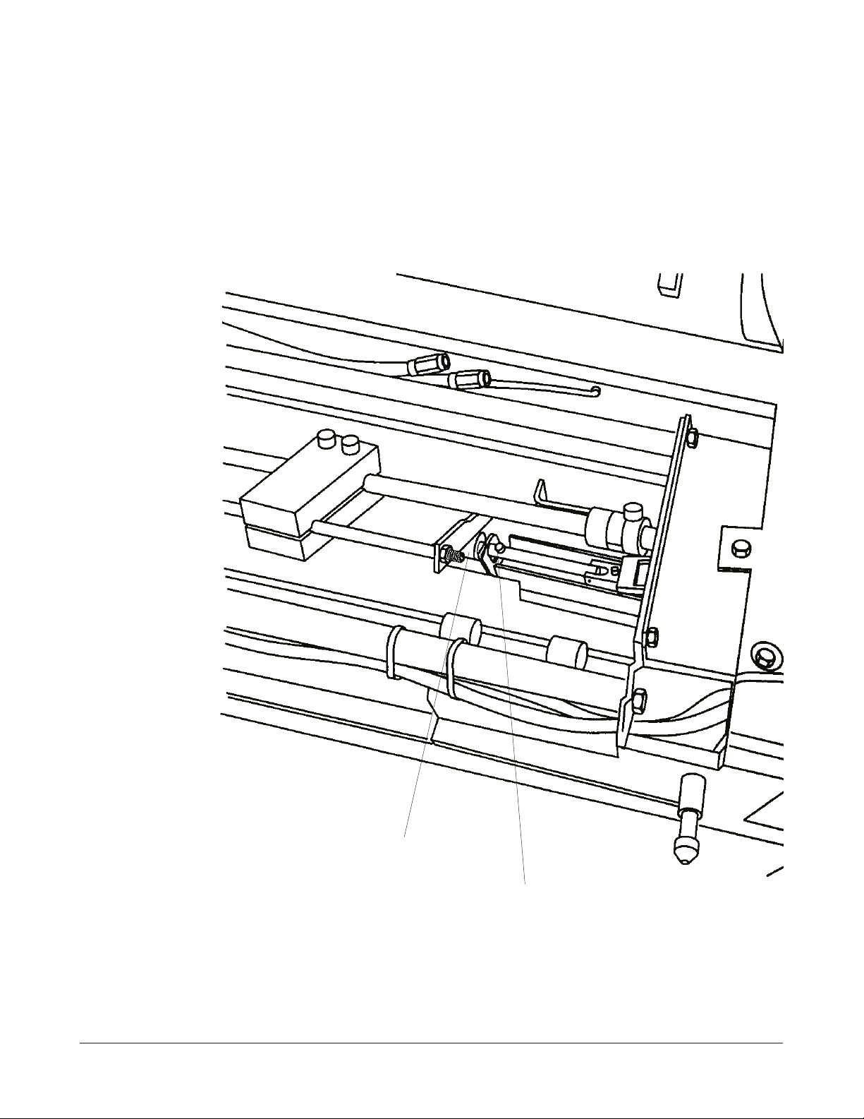
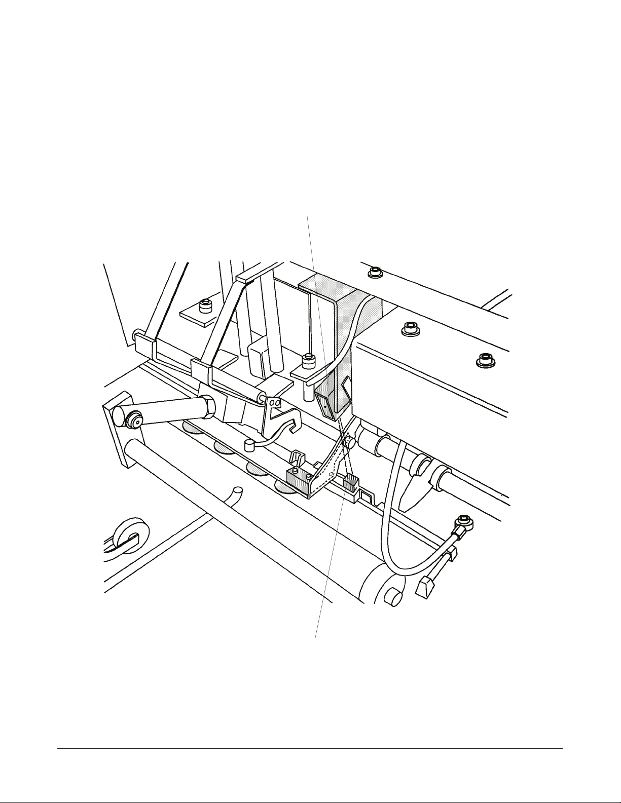
CONVEYER END STOP
A CONVEYER END STOP is installed. This END STOP eases the correct positioning of the
CONVEYER in case that the complete assembly had been removed from the ML700 PLUS.
The END STOP is retrofittable into the ML700. It is part of Modification 28.
CONVEYER END STOP
figure 1-2
12/1998 1-2 KODAK AG, Stuttgart
INTRODUCTION 3053-3
CASSETTE SUCKER BAR GUIDE ROLLER and CASSETTE SUCKER BAR
The position of the CASSETTE SUCKER BAR GUIDE ROLLER can be easily adjusted with
an ADJUSTMENT SCREW.
The new CASSETTE SU CKER BAR can be pivoted to match au tomatically the cur vature of
the CASSETTE. This improves the picking up of the film from the CASSETTE. See the
drawing on the nex t page.
Both alterations are available as Modification 28 for the ML700.
CASSETTE SUCKER BAR
GUIDE ROLLER
ADJUSTMENT SCREW
figure 1-3
KODAK AG, Stuttgart 1-3 12/1998
3053-3 INTRODUCTION
PIVOT
figure 1-4
12/1998 1-4 KODAK AG, Stuttgart
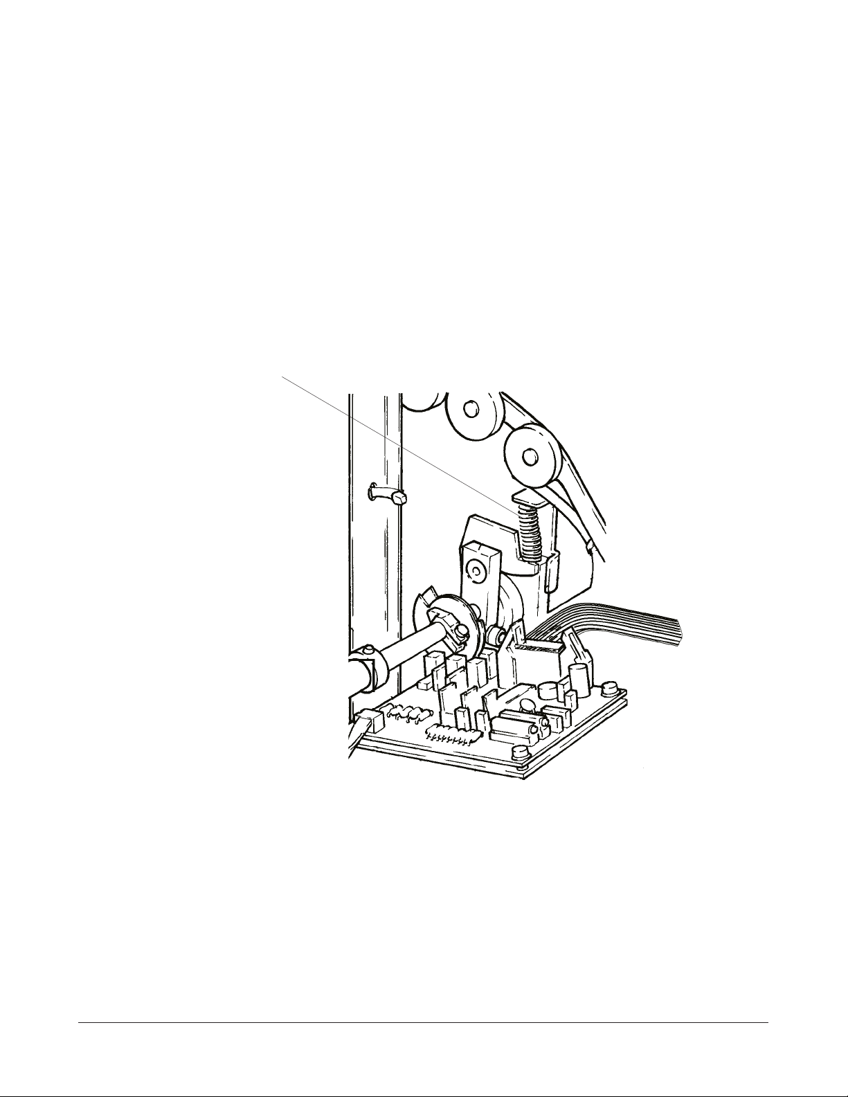
INTRODUCTION 3053-3
FILM POCKET DETENT SPRING
A stronger FILM POCKET DETENT SPRING is used to hold the FILM POCKET in place.
This alteration is available as part of Modification 28 for the ML700.
DETENT SPRING
figure 1-5
KODAK AG, Stuttgart 1-5 12/1998
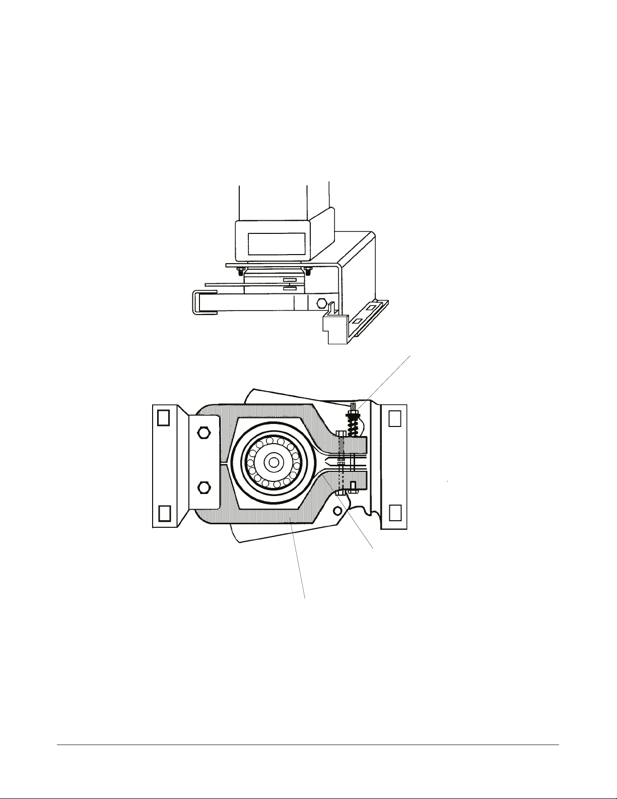
3053-3 INTRODUCTION
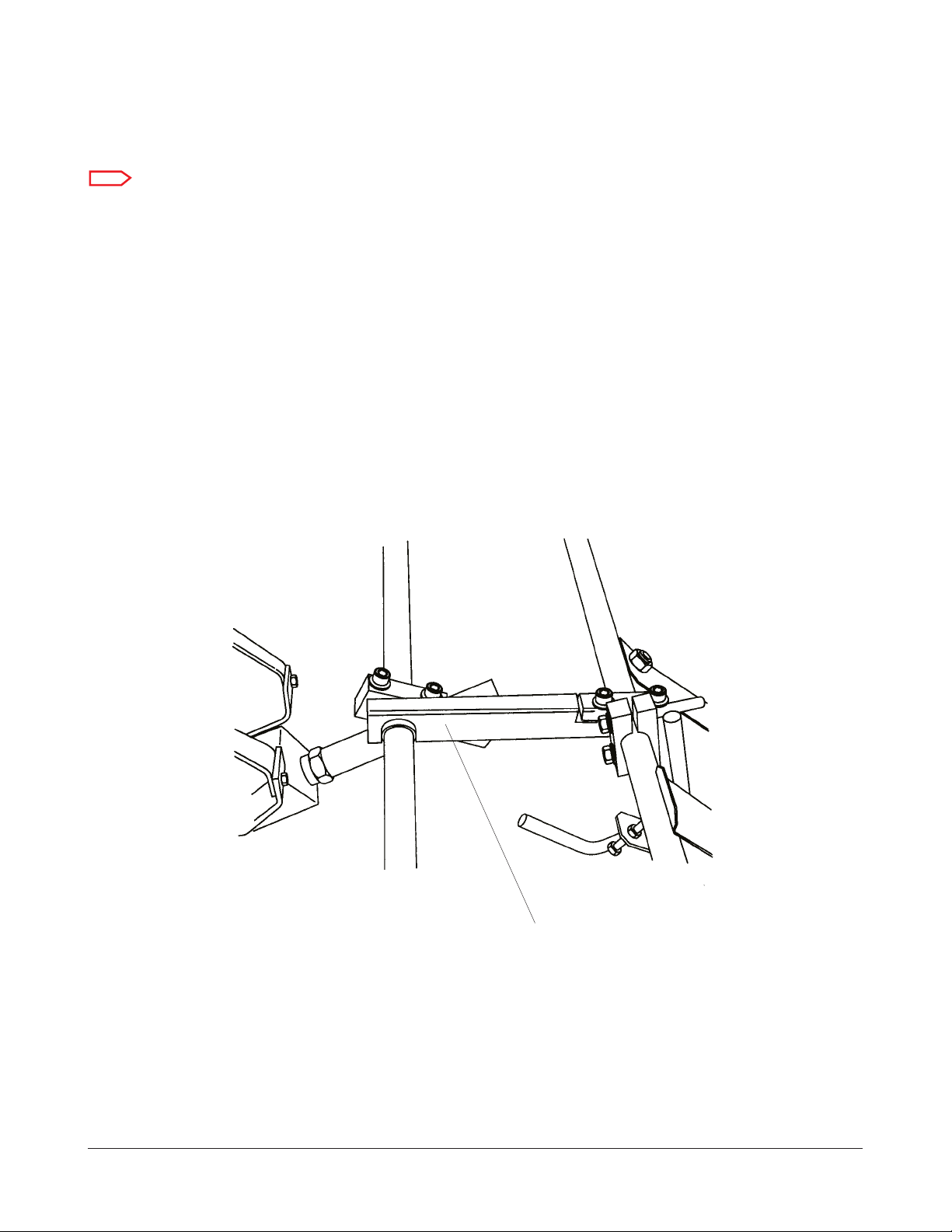
CENTRING BRAKE
BRAKE BELT TENSIONERS are used in addition to the BRAKE BELT. The braking force is
adjustablewithanADJUSTMENTNUT.
This alteration is available as Modification 26 for the ML700.
BRAKE BELT TENSIONER
ADJUSTMENT NUT
BRAKE BELT
figure 1-6
12/1998 1-6 KODAK AG, Stuttgart
INTRODUCTION 3053-3
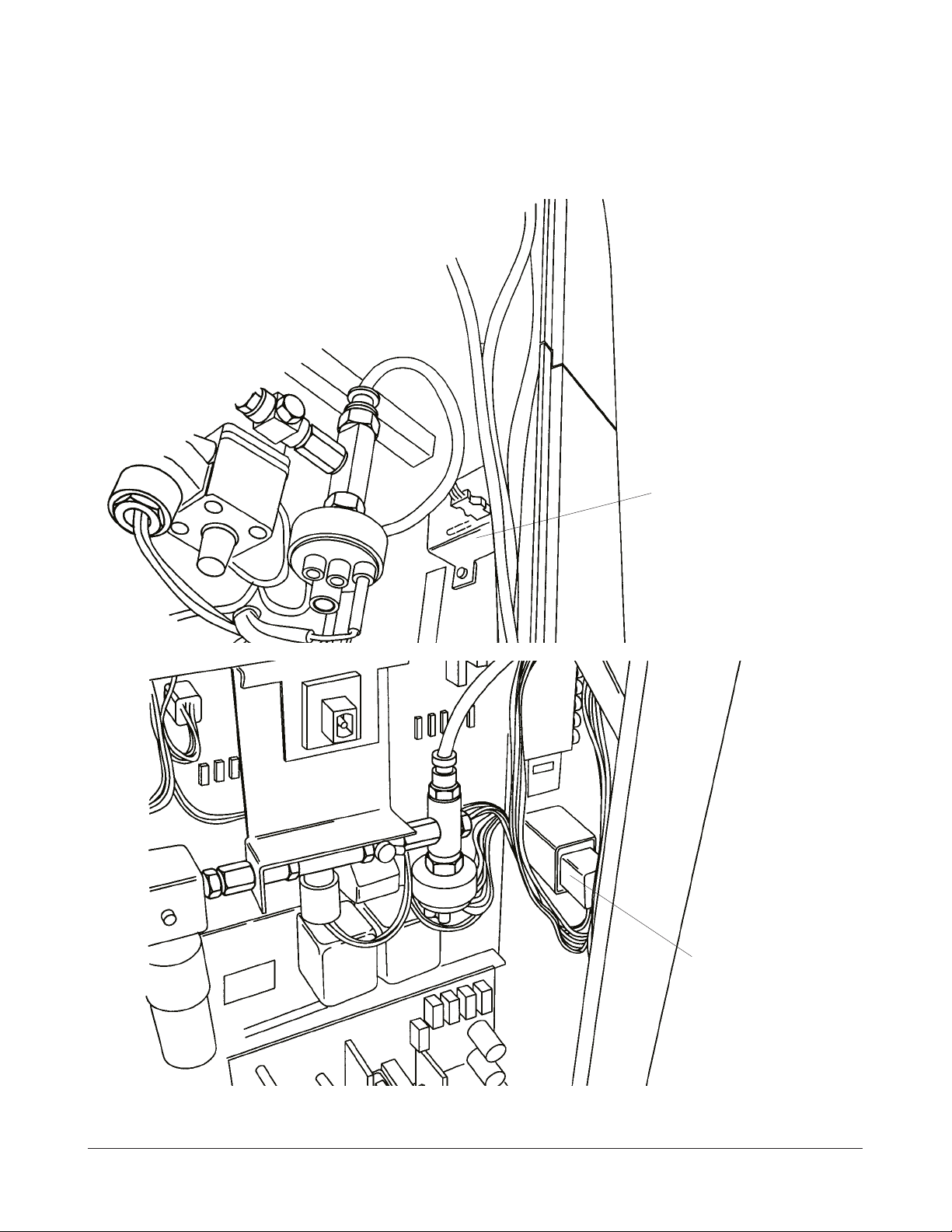
MAGAZINE DOOR SOLENOID / MAGAZINE DOOR INTERLOCK
Instead of 2 DOOR SOLENOIDS just 1 is used at a different position. A new DOOR
INTERLOCK SWITCH is used too.
These alterations are not retrofittable to the ML700 .
MAGAZINE DOOR
SOLENOID
MAGAZINE DOOR
INTERLOCK
figure 1-7
KODAK AG, Stuttgart 1-7 12/1998
3053-3 INTRODUCTION
DISPLAY
Note
This DISPLAY has no SELF TEST FUNCTION.
The PLASMA TUBE DISPLAY is replaced with a LCD DISPLAY.
This alteration is not retr ofittable to the ML7 00.
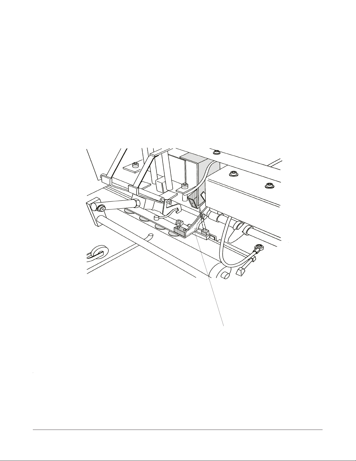
SPACER OPENER SHAFT
A SPACER at the OPENER SHAFT prevents it from excessive vibrations. Due to the strong
vibrations SWITCHES S4, S5, S6 could become actuat ed at the wro ng time.
This alteration is available as MODIFICATION 25 for the ML700
SPACER
figure 1-8
12/1998 1-8 KODAK AG, Stuttgart
INTRODUCTION 3053-3
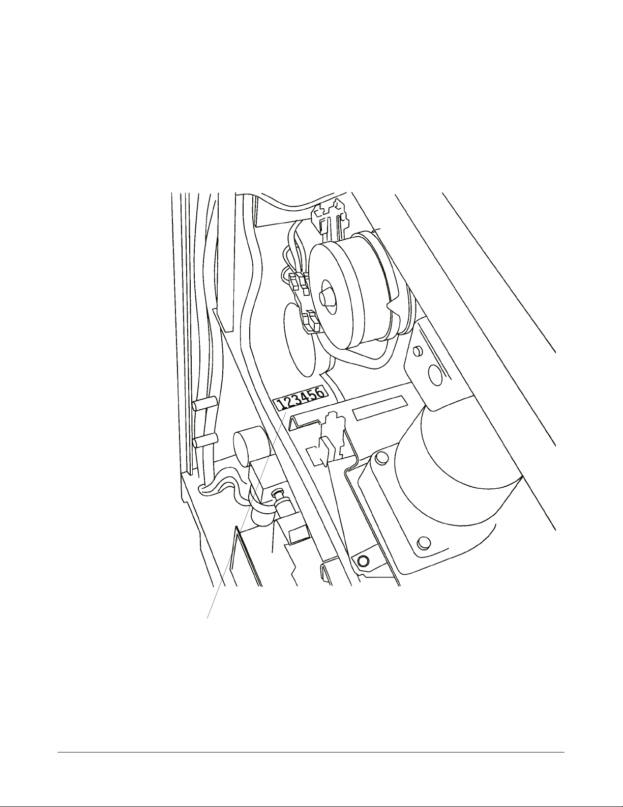
TOTAL CYCLE COUNTER
The TOTAL CYCLE COUNTER is relocated. The COUNTER can be accessed after lifting the
TOP COVER.
TOTAL CYCLE COUNTER
figure 1-9
KODAK AG, Stuttgart 1-9 12/1998
3053-3 INTRODUCTION
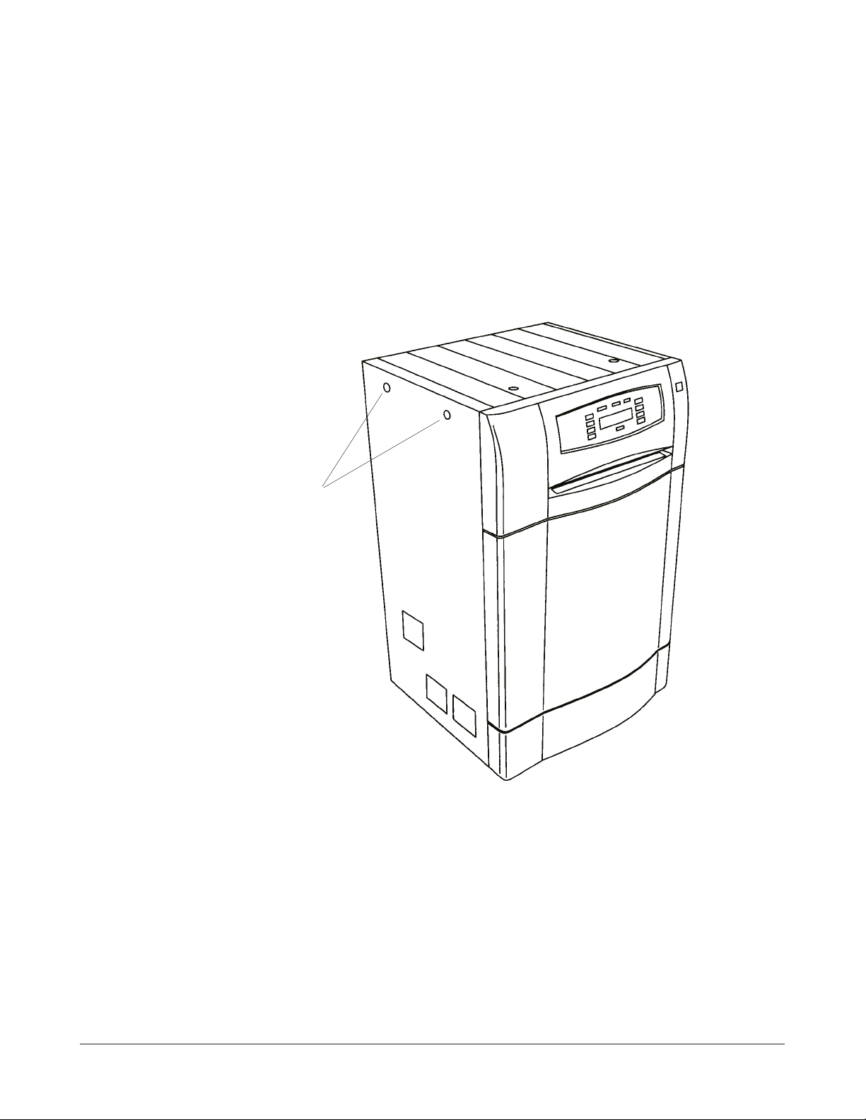
PANELS
The PANELS are ch anged. Material a nd shape is c hanged. The Pane ls are fixed with
QUARTER TURN SCREWS. To release the PANEL turn the SCREWS ¼ turn ccw. To fix the
PANEL turn the SLOT of the SCREW vertical and then jus t press on th e SCREW HEA D.
The Panels are not retrofittable to the ML700.
QUARTER TURN SCREW
figure 1-10
12/1998 1-10 KODAK AG, Stuttgart
INTRODUCTION 3053-3
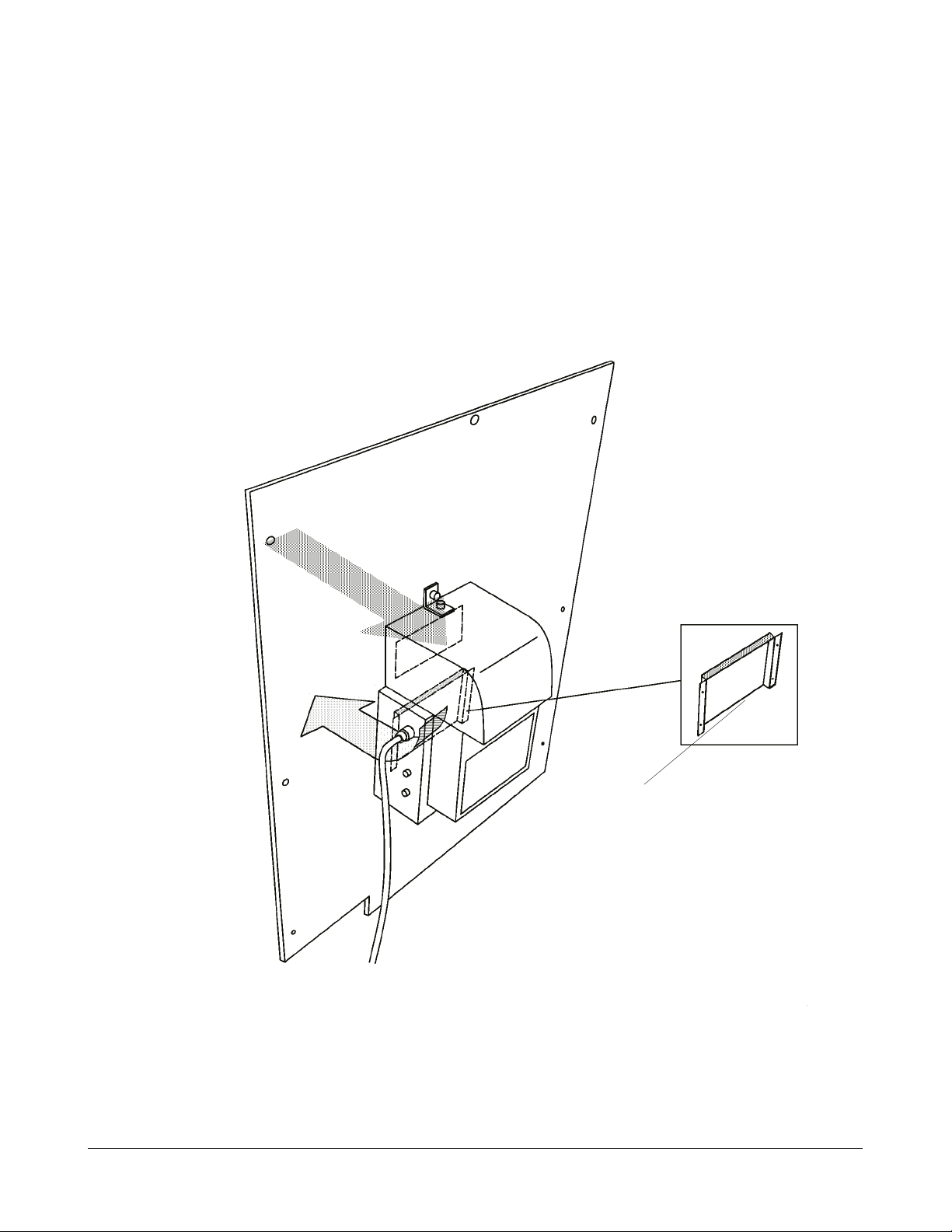
HUMIDIFIER
To increase the efficiency of the HUMIDIFIER the air flow is changed. With the new design,
air is sucked out of the ML700, routed through the HUMIDIFIER and blown back into the
ML700. It is now possible to raise the humidity up t o 40%. The factory setting is 40%.
This alteration is available as Modification 27 for the ML700.
Opening of HUMIDIFIER COVER
PLATE
figure 1-11
KODAK AG, Stuttgart 1-11 12/1 998
3053-3 INTRODUCTION
POWER SUPPLY
An improved POWER S UPPLY is ins talled. This Powe r Supply does not become a
modification for the ML700. If the POWER SUPPLY of the ML700 fails order the new one
from the ML700 PLUS as a spare part.
TEMPLATES
The LCD DISPLAY of the ML700 PLUS differs in size from the PLASMA DISPLAY of the
ML700. Therefore the old templates (used for diagnostics and sensor test) cannot be used for
the ML700 PLUS.
TEMPLATE ML700 PLUS ML700
PART NUMBER TL 5089
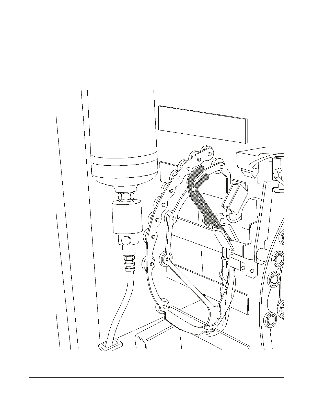
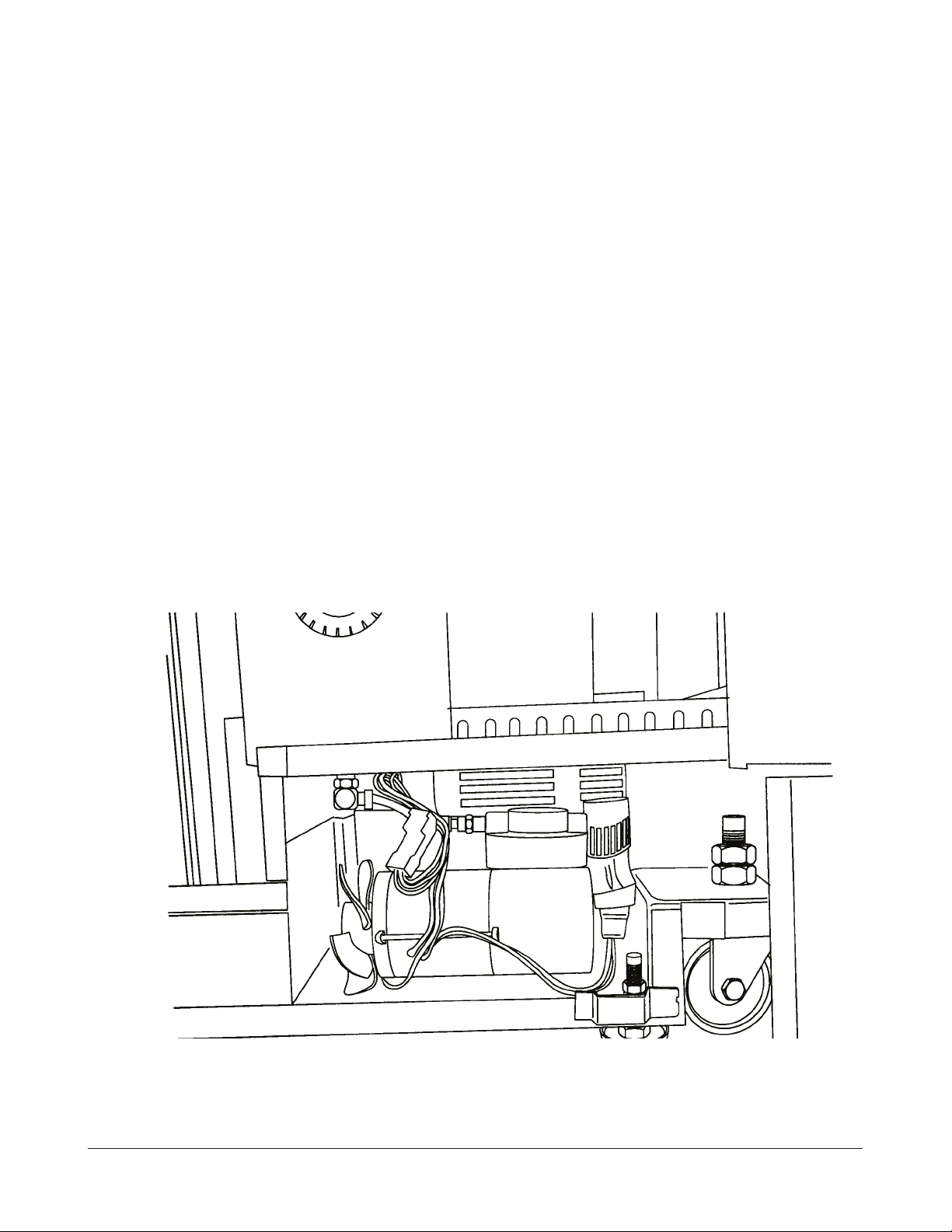
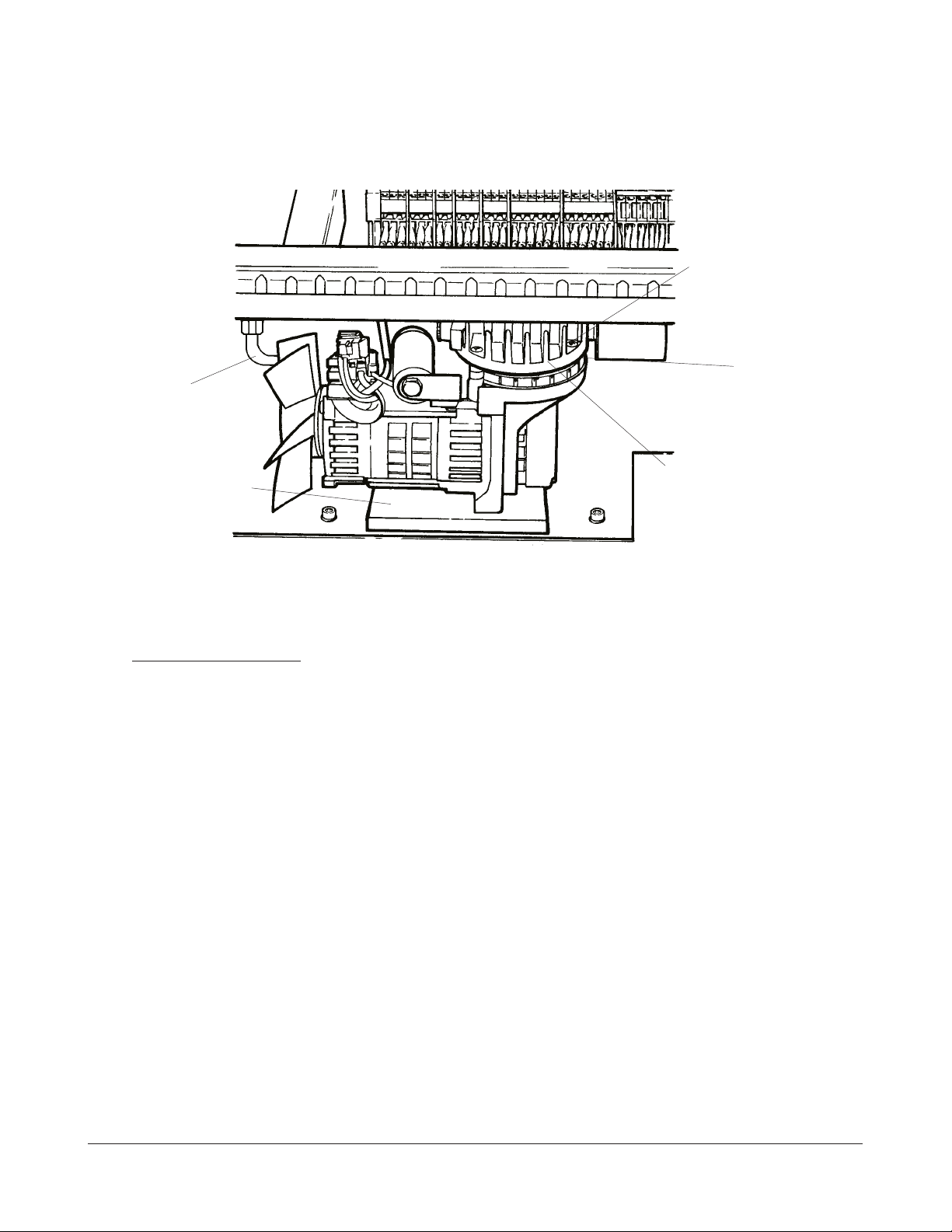
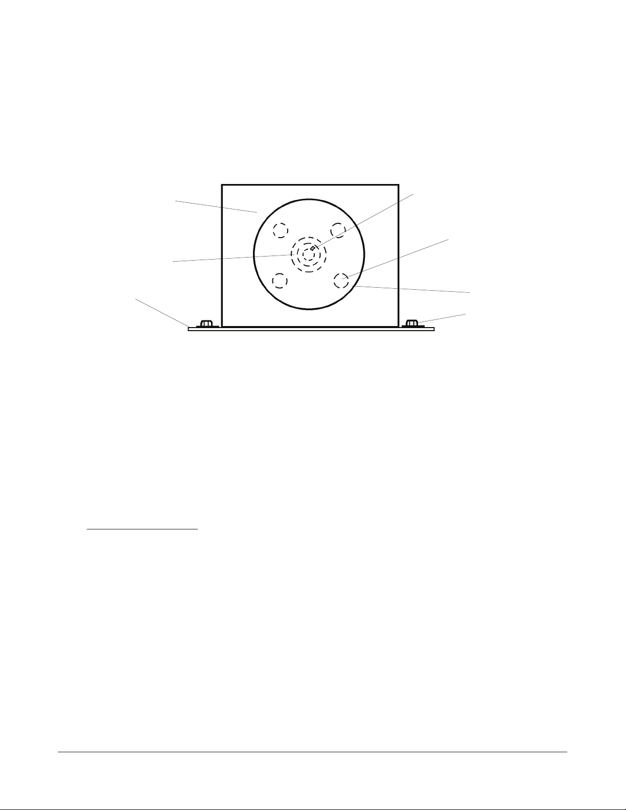
COMPRESSOR
The old COMPRESSOR is replaced with a new one. The new one has an increased life time
and is muchquieter. With the new COMPRESSOR it takes approximately 40 seconds to fill up
the AIR BOTTLE. The new COMPRESSOR can be installed on both the ML700 and ML700
Plus.
figure 1-12
12/1998 1-12 KODAK AG, Stuttgart
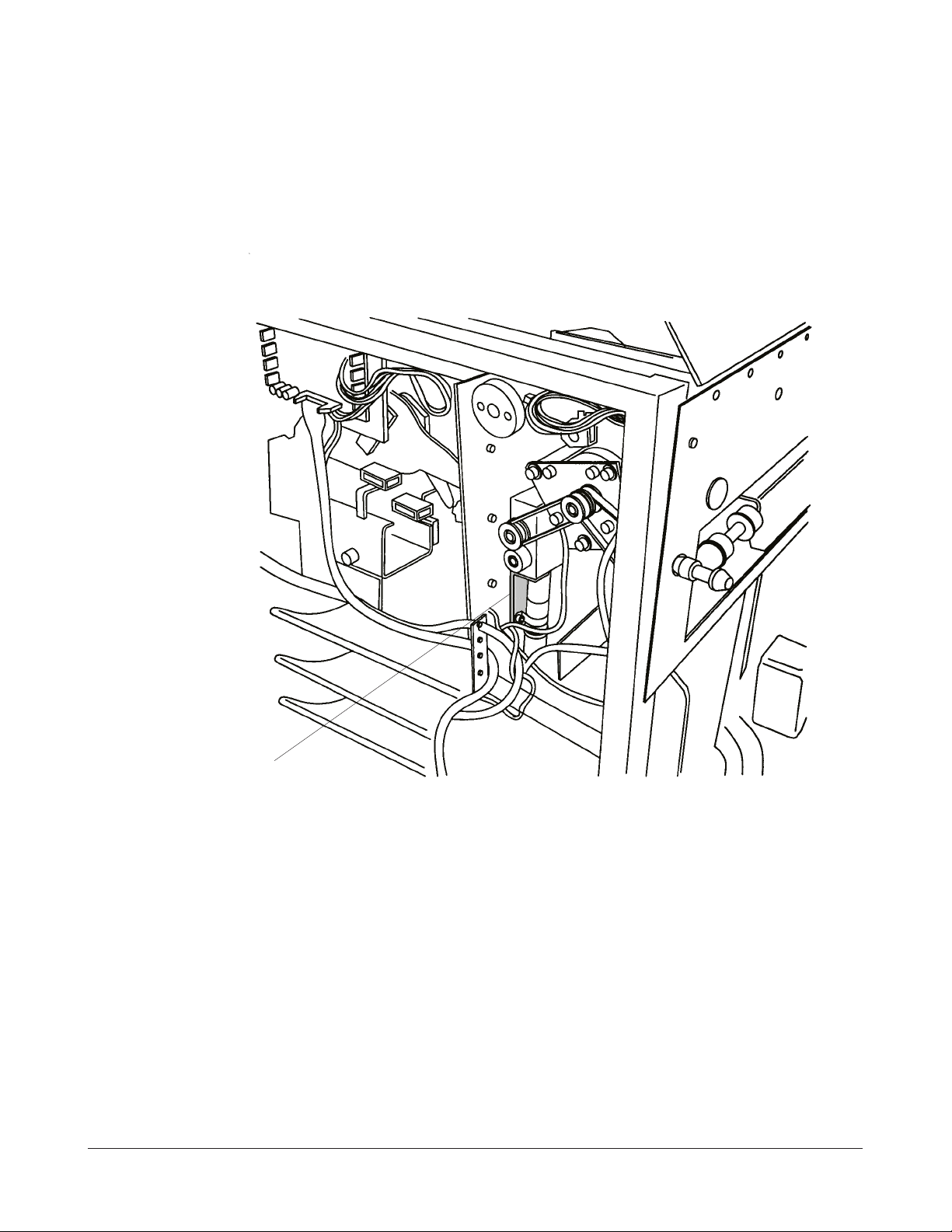
INTRODUCTION 3053-3
SENSOR FOC B6
SENSOR FOC is replaced with the same type of sensors used for FILM PRE SENCE
DETECTION.
SENSOR FOC B6
REFLECTIVE STICKER
figure 1-13
KODAK AG, Stuttgart 1-13 12/1 998

3053-3 INTRODUCTION
TUNNEL
TUNNEL SENSOR FRONT and TUNNEL SENSOR REAR are replaced with a new type. The
new SENSORS detect the reflection from the film surface.
2 GUIDES, 1 left and 1 right are added to guide the FILM S through the TUNNEL CONVEYER
better into the PROCESSOR.
PRINTED CIRCUIT BOARD PCB A4 PLUS
The new PCB A 4 PLUS c an be used in ML700 and in ML700 Plus. If used in a ML70 0 PLUS
Jumper E1 must be in. If used in a ML700 Jumper E1 must be out.
In the ML700 PLUS a different FRONT DOOR SOLENOID is used. This SOLENOID has a
cycle time of 15%. The FRONT DOOR SOLENOID of the ML700 has a cycle time of 100%.
Due to the 15% cycle time the new SOLENOID draws more current than the old one. This
overloads the drivers on PCB A4. For this reason an altered PCB A4 is used for the ML700
PLUS. DO NOT USE PCB A4 FROM THE ML700 IN A ML700 PLUS. PCB A4 W ILL FAIL!
PRINTED CIRCUIT BOARD PCB A7 Plus
!
Caution
PCB A7 Plus mus t not be used in a ML700
Due to the improved DOUBLE FILM DETECTION a new PCB A7 Plus is used.
PRINTED CIRCUIT BOARD PCB A9 Plus
!
Caution
PCB A9 Plus must not be used in a ML700
Due to the replaced SENSORS FOC / TSF and TSR a new PCB A9 Plus is used. The
SENSOR REPLACEMENT and the change of PCB A9 allow the use of INFRARED FILMS.
SOFTWARE
Note
THIS SOFTWARE CANNOT BE USED FOR THE ML700.
A new software, VERSION 5.0, is used for the ML700 PLU S.
1. The software is adapted to the LCD DISPLAY.
2. After pressing BUTTON 4 (open FRONT DOOR) the DOOR SOLENOID is energised
for 3 seconds. If during these 3 seconds the FR ONT DOOR doe s not open (maybe it is
mechanically blocked), the STANDA RD SCREEN is displayed.
12/1998 1-14 KODAK AG, Stuttgart

INTRODUCTION 3053-3
After Start of SERIAL UN LOAD the DOOR SOLENOID is energised for 3 sec onds. If
during these 3 secon ds the FRONT DOOR does not open, the m essage “NO
MAGAZINE SELECTED FOR SERIAL UNLOAD” is displayed. If BUTTON C is pressed
the STANDARD SCREEN will be displayed again.
3. If the INCH FLAG is set to 1, 14x17 in X is displayed and not 35x43 cm X.
4. The size 11x14 in V is eliminated.
5. All languages are in 1 (one) EPROM.
6. After unloading the CASSETTE it is checked once more with the FILM PRESENCE
DETECTOR BOTTOM if there is a FILM on the bottom screen of the CASSETTE. This
is done prior to loading the new FILM. If there is a FILM, the CASSETTE is transported
out and the message PLEASE INSERT CASSETTE AGAIN is displayed.
KODAK AG, Stuttgart 1-15 12/1 998

3053-3 INTRODUCTION
12/1998 1-16 KODAK AG, Stuttgart

REPLACEMENTS 3053-3
CHAPTER 2
Note
DO NOT LOOSEN THE RED MARKED SCREWS OR NUTS. THESE ARE FACTORY
ADJUSTMENTS ONLY.
KODAK AG, Stuttgart 2-1 12/1998

3053-3 REPLACEMENTS
SPECIAL TOOLS
OPENER TOOL ..............................................................................................9193396
OPENER GAUGE...........................................................................................9193386
TEMPLATE, CASSETTE LID C1, C2, C3 ..................................................9194501
TEMPLATE, TUBESIDE SCREEN C1, C2, C3.........................................9194511
TEMPLATE, WINDOW C1 ............................................................................9194521
TEMPLATE, LID SCREEN C-2 ....................................................................9194531
TEMPLATE, WINDOW C-3 ...........................................................................9194541
ALLEN KEY 10mm .........................................................................................9197313
METRIC OPEN END WRENCH, 30mm......................................................9901901
TORX WRENCH SET ....................................................................................TL 3261
VACUUM GAUGE...........................................................................................29010170
PRESSURE GAUGE ......................................................................................9186781
METRIC ALLEN SET .....................................................................................TL 2764
METRIC ALLEN SET BALL ENDED ...........................................................TL 3789
METRIC OPEN END WRENCH SET..........................................................TL 2765
FILTER, for adjusting the DOUBLE FILM SENSOR ................................9191223
SERVICE KEY, INTERLOCK SWITCHES ..................................................9901918
METRIC SOCKET WRENCH SET...............................................................G9901934
ESD KIT ...........................................................................................................TL3346
DENTIST MIRROR.........................................................................................TL 2753
TEMPLATE ML700.........................................................................................TL 5089
TEMPLATE ML700 PLUS .............................................................................TL 5089
SUCKER GAUGE ...........................................................................................9194841
12/1998 2-2 KODAK AG, Stuttgart
REPLACEMENTS 3053-3
REPLACEMENTS
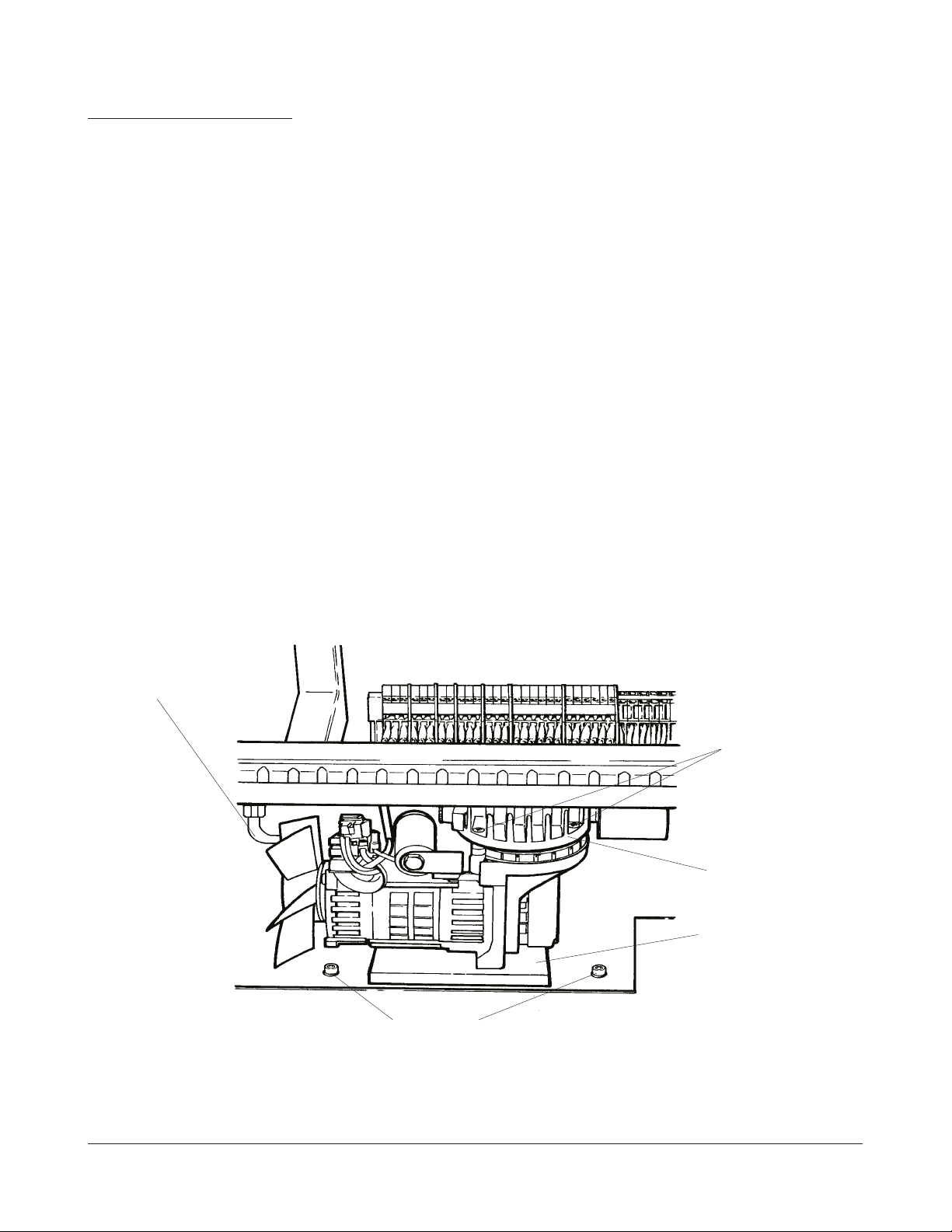
REPLACEMENT COMPRESSOR ASSY M9
1
. Powe r down ML 700.
2. Unplug ML 700.
3.OpenleftSIDEPANEL.
4. Take off PROTECTIVE COVER with FILTER. (No FILTER in ML700 Plus).
5. Unplug COMPRESSOR M9.
6. Unscrew CONNECTOR with PRESSURE TUBING.
7. Take out MOUNTING SCREWS.
8. Lift front of COMPRESSOR BASE.
PRESSURE TUBING
PHILLIPS
SCREWS (4)
COMPRESSOR
COVER
COMPRESSOR
BASE
MOUNTING SCREW
figure 2-1
KODAK AG, Stuttgart 2-3 12/1998
3053-3 REPLACEMENTS
9. Pull out COMPRESSOR ASSY.
10. Install new COMPRESSOR.
11. Connect PLUG and P RESSURE TUBING.
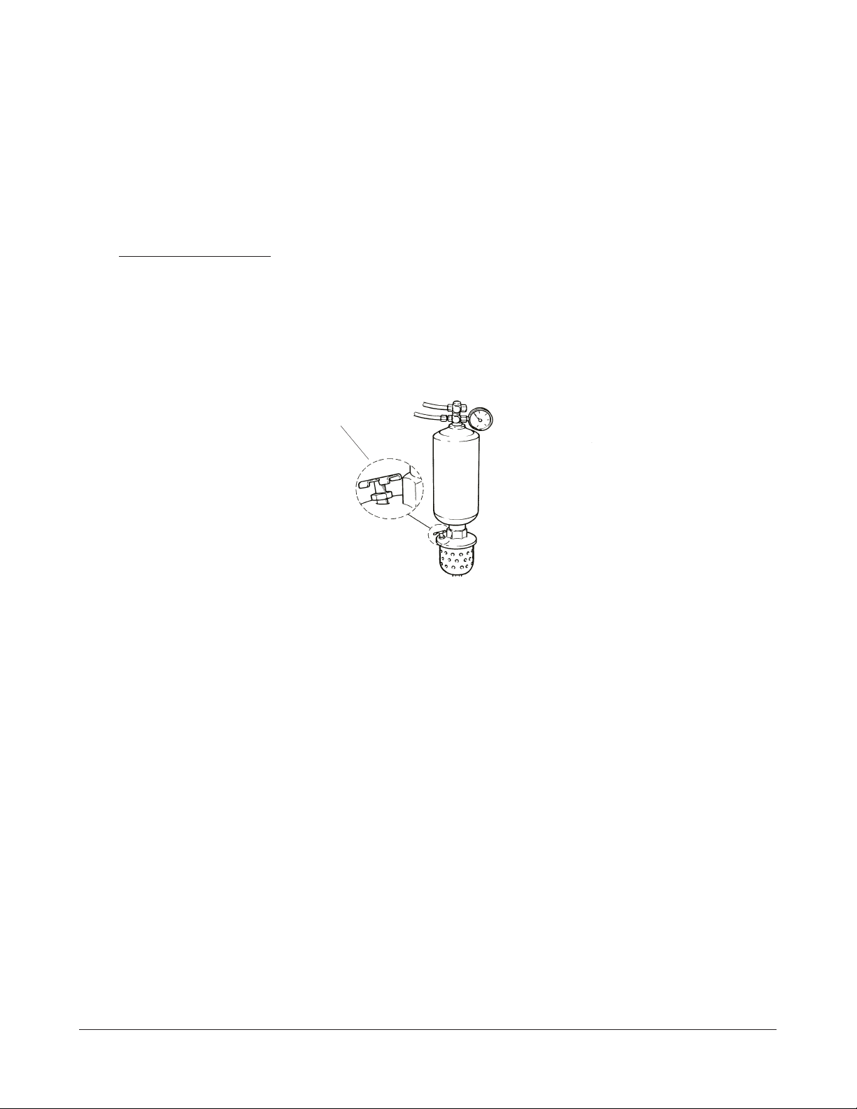
FUNCTION TEST.
1. Power up ML 70 0.
2. Actuate INTERLOCK OVERRIDE.
3. Open the PRESSURE RELEASE VALVE.
PRESSURE RELEASE VALVE
figure 2-2
4. COMPRESSOR starts.
5. Close PRESSURE RELEASE VALVE.
6. COMPRESSOR stops when pressure reaches +4 BA R.
7. Check system f or leakage.
REPLACEMENT COMPRESSOR DIAPHRAGM
1
. Remove COMPRE SSOR ASSY.
2. Mark position of COMPRESSOR COVER.
3. Take out 4 PHILLIPS SCREWS. Observe the 8 SPACERS.
4. Replace COMPRESSOR DIAPHRAGM.
12/1998 2-4 KODAK AG, Stuttgart
REPLACEMENTS 3053-3
5. Mount COMPRESSOR COVER.
6. Install COMPRESSOR ASSY.
PHILLIPS SCREWS (4)
PRESSURE TUB-
ING
COMPRESSOR
BASE
FUNCTION TEST.
1. Power Up ML 700.
2. Actuate INTERLOCK OVERRIDE.
3. Release pressure of AIR RESERVOIR.
SPACERS (8)
not shown
COMPRESSOR COVER
figure 2-3
4. COMPRESSOR starts.
5. COMPRESSOR stops when pressure reaches +4 bar.
6. Check system f or leakage.
REPLACEMENT CASSETTE TRANSPORT MOTOR M1
1
. Powe r down ML 700.
2. Unplug ML 700.
KODAK AG, Stuttgart 2-5 12/1998
3053-3 REPLACEMENTS
3. Unplug MOTOR M1.
4. Mark position of MOUNTING BRACKET on BASE.
5. Remove HEX SCREWS.
6. Take out MOUNTING BRACKET with MOTOR M1.
MOUNTING BRACKET
GEAR
BASE
figure 2-4
7. Mark position of MOTOR M1 on MOUNTING BRACKET.
8. Remove PHILLIPS SCREW S.
9. Loosen Setscrew and take of GEAR.
SET SCREW
PHILLIPS SCREWS (4)
MOTOR M1
HEX SCREWS (4)
10. Install new MOTOR M1.
FUNCTION TEST.
1. Power Up ML 700.
2. Actuate INTERLOCK OVERRIDE.
3. EnterSERVICEMODEFDABDay,Day,9,9.
4. Select Option 7.1 (TEST MODE CASSETTE IN/OUT).
5. Run MOTOR TEST (forward / reverse ).
6. Leave SERVICE MODE.
7. Key in 3585 to bring all MOTORS to HOME POSITION.
12/1998 2-6 KODAK AG, Stuttgart
 Loading...