

Page 1

MODIFICATION INSTRUCTIONS
for the
KODAK MULTILOADER 700
Service Code 3053
Modification No. 9
Type 1 s e lective
Publication No. MA3053-9
4/1990
Purpose:
To remove and prevent corrosion in the ML 700 and the TUNNEL
SER IAL NUMBER S : Up to SN 1245 for 50 Hz units.
Up to SN 5106 for 60 Hz units.
INSTALLAT ION TIME: Approx. 1 2 hour s for sev ere cor r oded units. Down time of unit: approx. 72
hours
SPECIAL TOOLS: OPENER GAUGE 9193386
PARTS R EQUIREMENTS: See parts list.
Page 2

PLEASE NOTE
T he information cont ained he r ein is ba sed on t he e x perience and kn ow ledge rel ating t o t he subject
mat t er gained by Koda k pr ior to publication.
No patent license is granted by this information.
Kodak r eserves the right to change th i s informati on w i th out n otice , and makes no war ranty,
express or implied, with respect to this information. Kodak shall not be liable for any loss or
damage, including consequential or special damages, res ulting from the use of this information,
even if los s or da mage is cause d by Kodak ’ s negligence or oth er fault.
MA3053-9 2 KODAK AG Stuttgart
Page 3

PARTS LIST
PART NO. DESCRIPTION QUANTITY
9192905.................... Mod Kit No. 9 includes:
4281636 .....................SCREW .............................................................................................................1
4281751 ......................SC REW .............................................................................................................4
4281931 ......................THREA D PIN.....................................................................................................1
4282011 ...................... SCREW .............................................................................................................4
4282691 ...................... SCREW .............................................................................................................2
4282692 ...................... SCREW .............................................................................................................8
4282746 ...................... SCREW..............................................................................................................2
4283111 .....................SCREW .............................................................................................................2
4282781 ...................... SCREW..............................................................................................................2
4470106 ..................... WASHER .......................................................................................................... 24
4480091 ..................... WASHER ..........................................................................................................2
4480166 ..................... WASHER ..........................................................................................................14
4480176 ..................... WASHER ..........................................................................................................6
4480271 ..................... WASHER ..........................................................................................................9
4480556 ..................... WASHER ..........................................................................................................4
4480037 ...................... WASHER ..........................................................................................................3
4500456 .....................CIRCLIP ............................................................................................................2
4500526 ...................... CIRCLIP ............................................................................................................32
4780031 ..................... PIN .................................................................................................................... 2
4853036 ..................... NUT ..................................................................................................................8
4853126 ..................... NUT ..................................................................................................................3
4853136 ..................... NUT ..................................................................................................................5
4853141 ..................... NUT ..................................................................................................................2
4853246 ..................... NUT ..................................................................................................................14
4853251 ..................... NUT ..................................................................................................................2
5001329 ..................... GLOVES ...........................................................................................................1
5001522 .....................FOAM R UBBER................................................................................................1
5574816 .....................EMER Y PAPER ................................................................................................2
5578311 .....................PAINT BRUSH ..................................................................................................1
5578316 .....................PAINT BRUSH...................................................................................................1
5578357 .....................PAINT BRUSH...................................................................................................1
5593933 .....................PLASTIC BAG ..................................................................................................1
5631285 .....................COTTON CLOTH .............................................................................................3
5631369 .....................ADHESIVE TAPE .............................................................................................1
6081850 .....................CABLE T IES .....................................................................................................25
9183526 .....................PLUG ................................................................................................................2
9185301 ..................... SHELL ..............................................................................................................1
9185311 ..................... ST OP BRACKET ..............................................................................................2
9185371 .....................BEAR ING ..........................................................................................................2
9185736 ..................... HOSE ...............................................................................................................1
9185561 .....................BEAR ING ..........................................................................................................1
9185611 .....................BEAR ING SHAFT .............................................................................................1
9185776 .....................SHAFT ..............................................................................................................1
9185831 .....................BEARING ..........................................................................................................4
KODAK AG Stuttgart 3 MA3053-9
Page 4

PART NO. DESCRIPTION QUANTITY
9185991 ..................... SPACER PLATE ...............................................................................................1
9187571 ..................... ROD ..................................................................................................................1
9188261 ..................... ROD ..................................................................................................................1
9191591 ..................... SUCKER BAR CAM ..........................................................................................2
4279346 .....................SCREW .............................................................................................................2
4500441 .....................TOOTHED WASHER .......................................................................................2
....................................PLASTIC COVER .............................................................................................1
....................................ESKAPON S115 ...............................................................................................1
....................................ANTICOR IT BW366 ..........................................................................................1
MA3053-9 4 KODAK AG Stuttgart
Page 5
REPLACEMENT OF CO RRODED PARTS
1. Switch off ML 700
2. Disconnect ML 700 from TUNNEL.
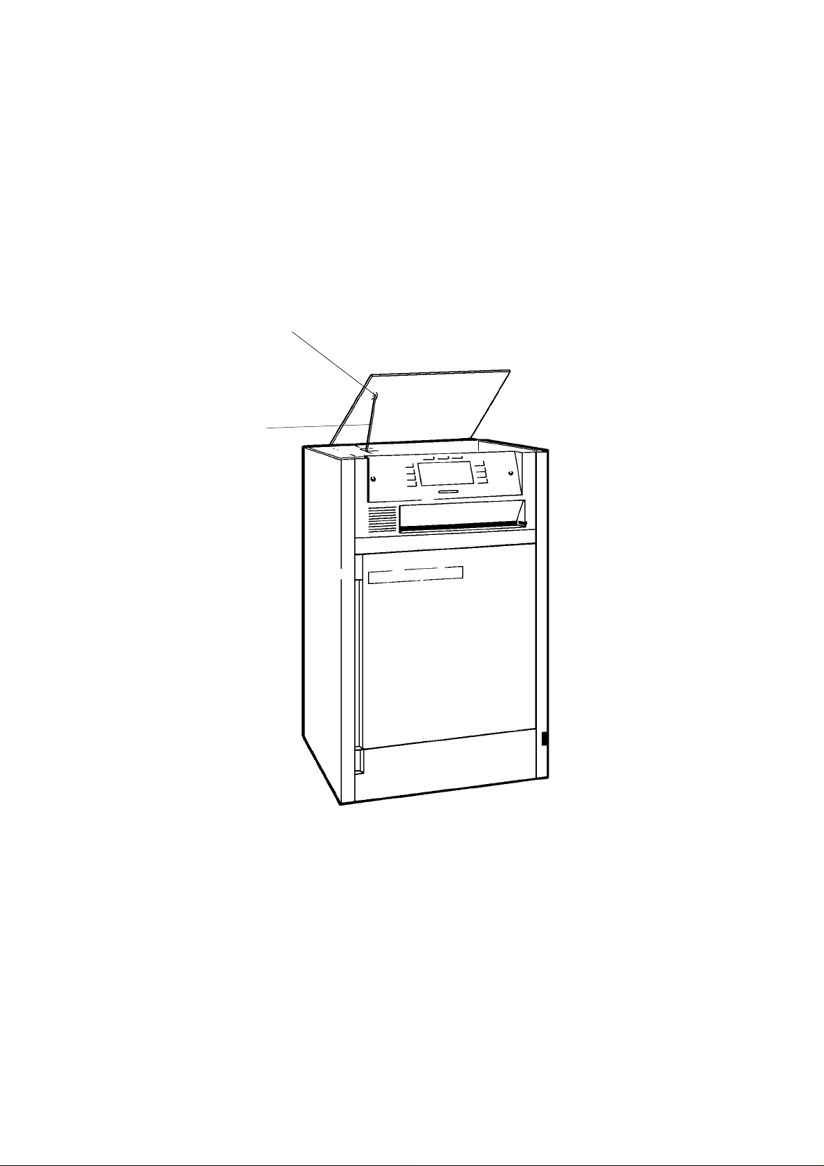
3. Remove TOP COVER
All standard parts in this Mod Kit are made out of stainless steel. Aluminum parts are coated
for protection against corrosion. Only most of the BEARINGS are made out of the same
material as before therefore they should only be replaced if they are corroded.
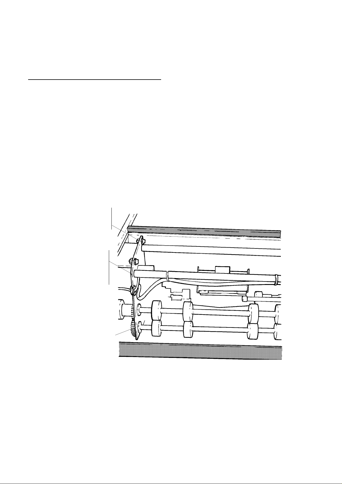
NUT (4) 4853136
SCRE W (4) 4281751
Note:
NUT (2) 4853141
WASHER (2) 4480091
TOOTHED WASHER (2)
BEARING (4) 9185831
4500441
figure 1
4. Remove and discard one SCREW 4281751 with NUT 4853136 and WASHERS 4480271 install new
SCRE W 4281751 with NUT 4853136 and WASHERS 4480271.
KODAK AG Stuttgart 5 MA3053-9
Page 6
Caution:
Do not loosen more than o ne SCREW at one time! It will be impossible
to readjust the CON VEYOR.
5. Repeat step 4 until all 4 SCREWS 4281751, all 4 NUTS 4853136 and all 8 WASHERS 4480271 are
exchanged.
6. Remove BEARINGS and install new BEARINGS 9185831. Do this only if BEARINGS are corroded.
7. Remove NUTS 4853141 with WASHERS 4480091 and TOOTHED WASHERS 4500441.
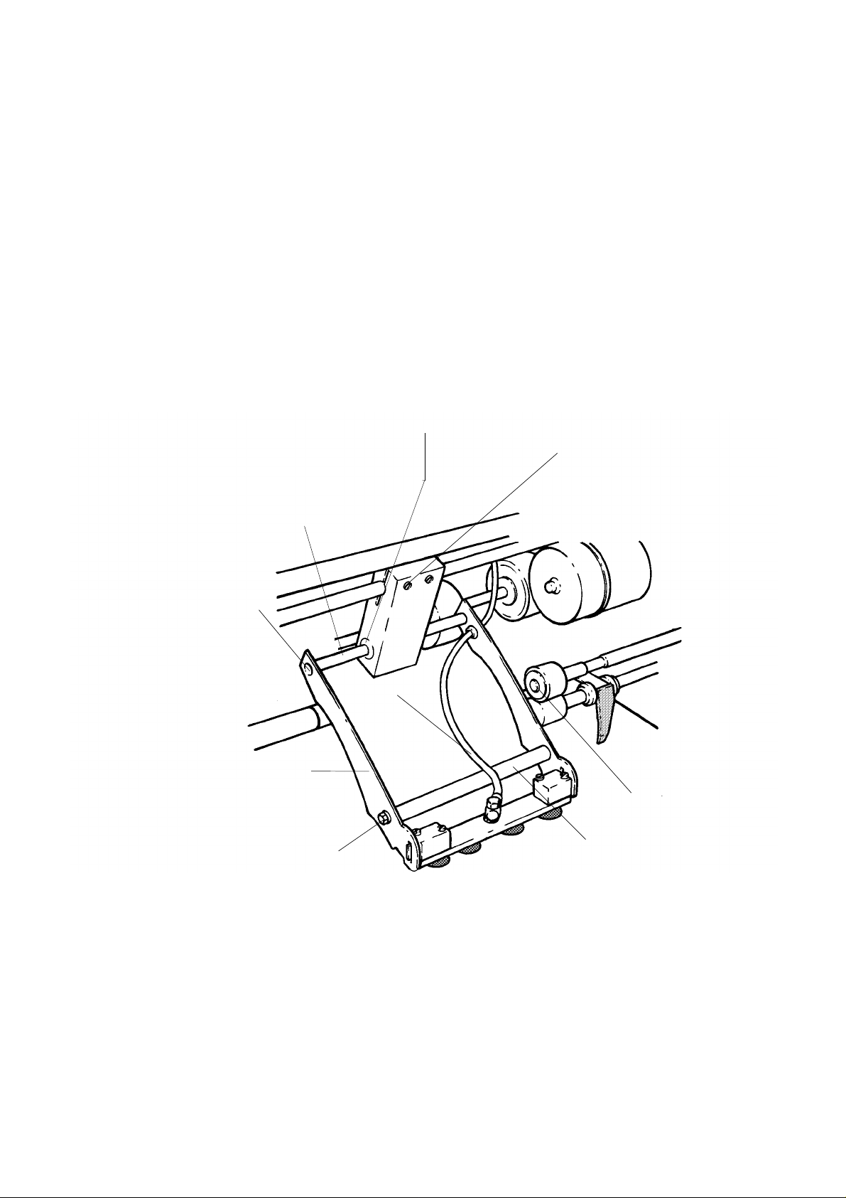
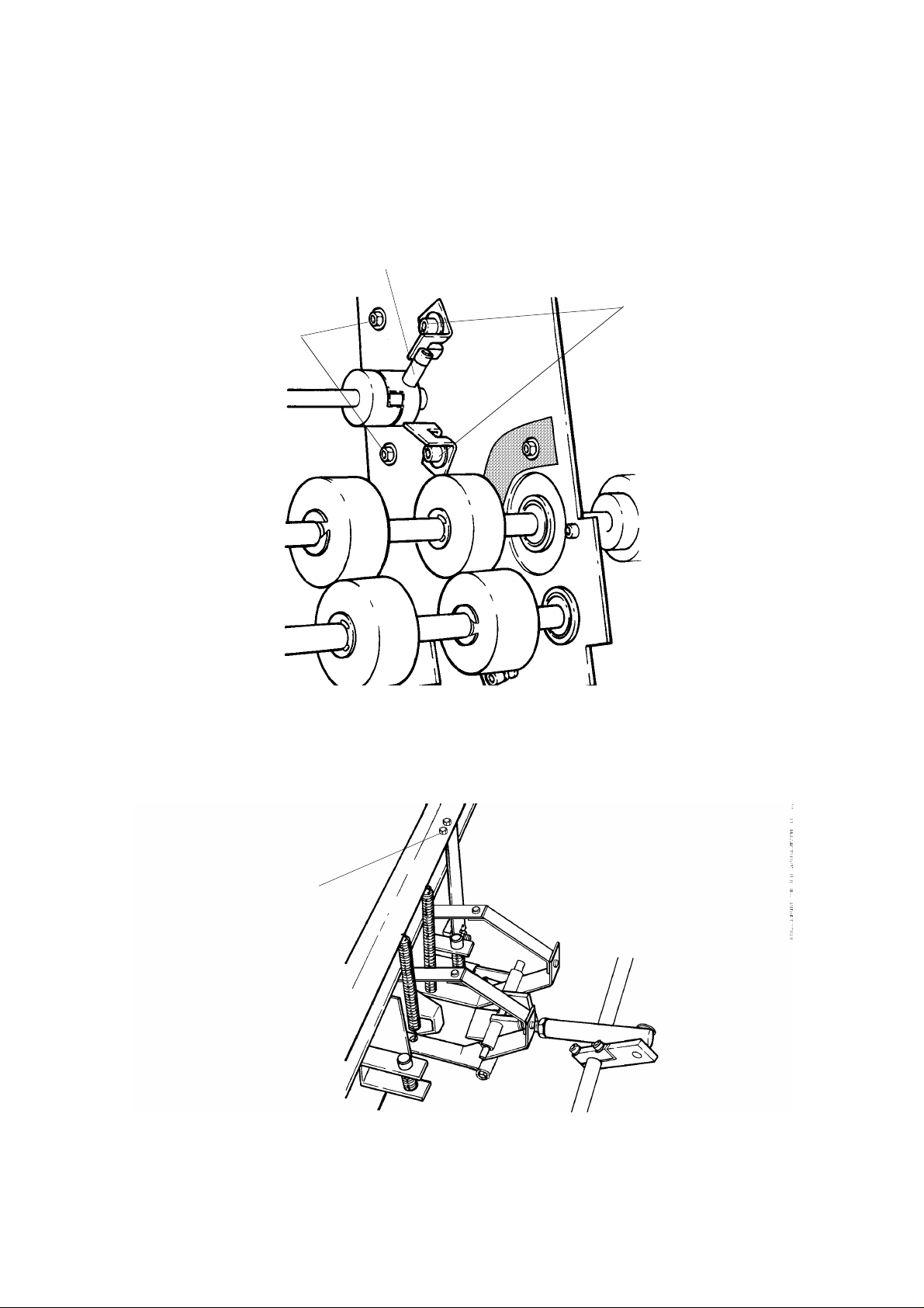
BEARING (2) 9185371
CIRCLIP (2) 4500456
THREA D P IN 4281931
BEARING SHAFT 9185611
SCRE W (2) 4283111
NUT (2) 4853036
WASHER (2) 4480176
HOSE 9185736
SUCKERBAR CAM (2) 9191591
SCRE W (2) 4282746
WASHER (2) 4480176
figure 2
SHAFT 9185776
8. Remove and discard one SCREW 4283111 install and tighten new SCREW 428311.
Note:
SCRE W (2) 4283121
WASHER (2) 4480551
Do not loosen both SCREWS 4283111 at the same time.
MA3053-9 6 KODAK AG Stuttgart
Page 7
9. Remove and discard the other SCREW 4283111 install new SCREW 4283111 .
10. Remove and discard indicated parts on figure 2 . Instal l new parts .
WASHER 4480271
NUT 4853136
WASHER 4480037
NUT 4853126
BEARING 9185561
figure 3
11. Remove and discard indicated parts on figure 3 . Instal l new parts .
PLUG (2) 9183526
figure 4
SPACER PLATE 9185991
KODAK AG Stuttgart 7 MA3053-9
Page 8
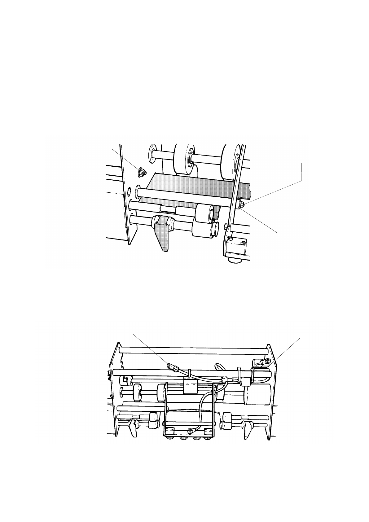
12. Remove indicated parts on figure 4 . Instal l new parts .
13. Re move and discard all CIRCLIPS. (They have no function.). See figure 5.
NUT (2) 4853251
WASHER (2) 4480037
figure 5
14. Remove 2 NUTS and 2 WASHERS and install NUTS 4853251 and WASHERS 4480037.
MA3053-9 8 KODAK AG Stuttgart
Page 9
15. Mark t he pos ition of STOP BRACK ETS. R emove an d discar d indica t ed par t s on fi gure 6. Install new
part s.
SCRE W 4281636
SHELL 9185301
NUT (3) 4853036
WASHER (2) 4480176
STOP BR A CK E T (2) 9185311
SCRE W (2) 4279346
WASHER (2) 4480556
figure 6
16. Remove indicated parts on figure 7 . Instal l new parts . See Not e on pa ge 10!
SCRE W (2) 4282781
NUT (2) 4853246
WASHER (4) 4470106
figure 7
KODAK AG Stuttgart 9 MA3053-9
Page 10
Note:
Do not loosen both SCREWS at the same time to prevent the MOUNTI N G BRACKET for the
SENSOR B6 (FOC) from a ltering.
17. Remove indicated part in fi gure 8. Insta ll new part s.
PIN 4780031
ROD 9187571
figure 8
MA3053-9 10 KODAK AG Stuttgart
Page 11

18. Remove and discard parts indicated in fi gu re 9 . Instal l new parts .
CIRCLIP 4486240
WASHER 4479810
(NOT SHOWN)
HOOK 9189761
figure 9
19. Re move CONVE YOR from TUNNEL. See figure 10.
CONVEYOR
figure 10
KODAK AG Stuttgart 11 MA3053-9
Page 12

20. Remove PIN with ROD. Install new PIN 4780031 and ROD 9188261.
21. Mark position of INTE RLOCK SWITCH S 2 0 . Replace indicated parts on INTE RLOCK S WITCH S2 0 .
Note:
Do not loosen both SCREWS at the same time .
PIN 4780031
ROD 9188261
INTERLOCK SWITCH S20
SCRE W (2) 4282691
NUT (2) 4853246
WASHER (4) 4470106
figure 11
22. Measure and record the adjusted length of SCREWS. Remove and discard SCREWS and NUTS. Install
SCRE WS 4282011 with NUT 4853036 to the recorded length. See figure 12.
SCRE W (4) 4282001
NUT (4) 4853036
figure 12
MA3053-9 12 KODAK AG Stuttgart
Page 13

23. Mark the position of SENSORS. Remove and discard SCREWS, WASHERS and NUTS on SENSORS.
Install new SCREW S 4282692, WASHERS 4470106 and NUTS 4853246 on the SENSORS.
Note:
Do not loosen both SCREWS on SENSOR at the same time for to keep misadjustments to a
minimum.
SENSOR
SCRE W (8) 4282692
NUT (8) 4853246
WASHER (16) 4470106
figure 13
24. Re move both SHAFTS with ROLLERS. See figure 14.
SHAFT WITH ROLLERS (2)
figure 14
KODAK AG Stuttgart 13 MA3053-9
Page 14

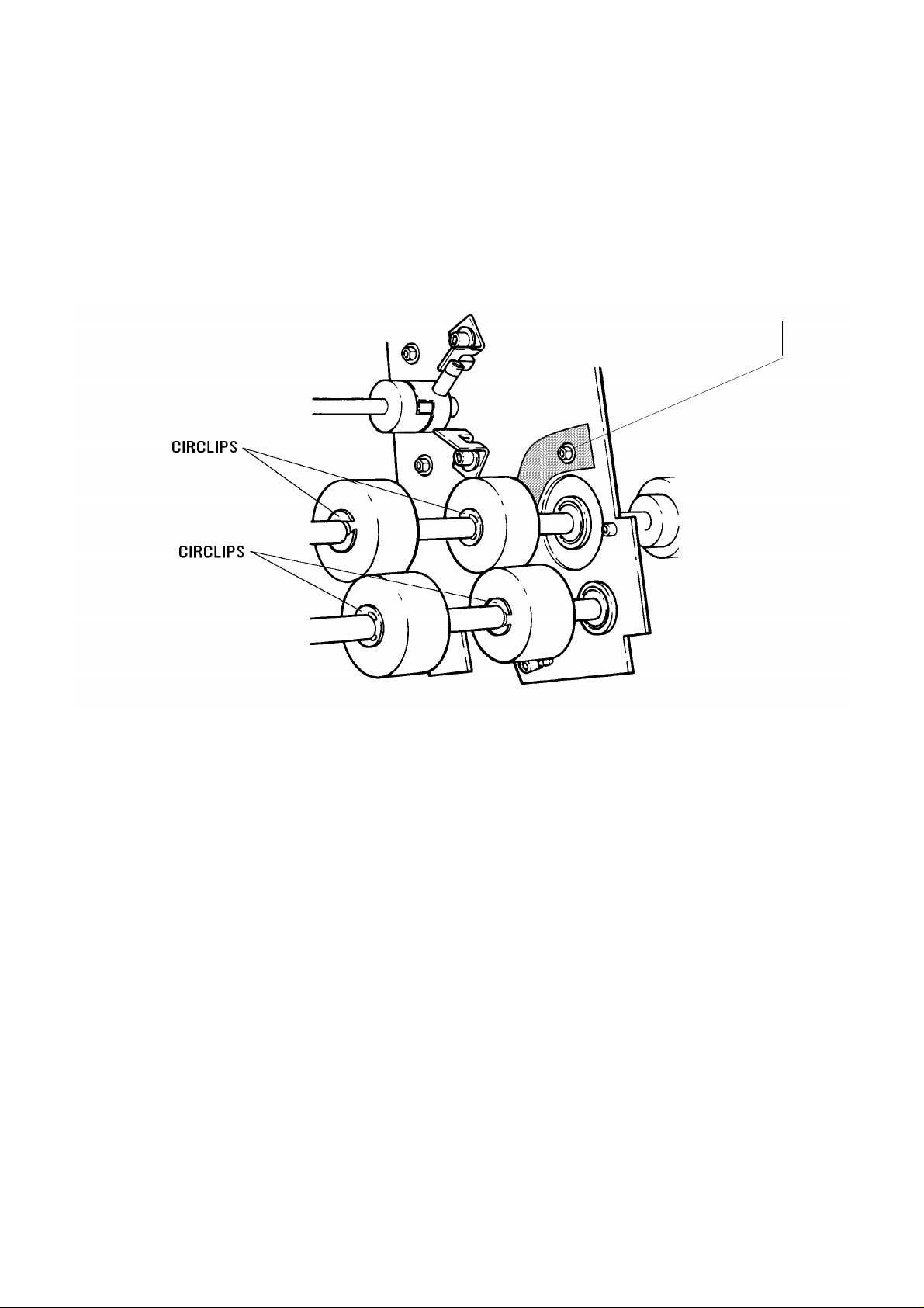
25. Remove and discard part i ndicated in figure 15. Insta ll new par t s.
CIRCLIP (14) 400526
WASHER (7) 4480166
figure 15
26. Install SHAFTS WITH ROLLERS using new HARDWARE. Se e figure 16.
CIRCLIP (4) 4500526
figure 16
MA3053-9 14 KODAK AG Stuttgart
Page 15
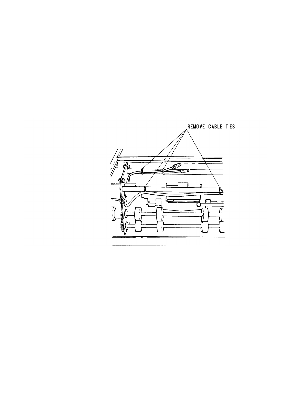
27. Remove CABL E TIES. Look f or corroded parts in the CONV EY OR . Remove corrosion with EME RY
PAPER.
Caution:
Cover SLIDING PLATES, ROLLERS, FILM POCKET and PCB’s to avoid
cont amination with ru st debris when you remove corrosion with EMERY
PAPER. Remove all rust debris from ML 700.
figure 17
28. Look for corroded parts in TUNNEL. Remove corrosion with EMERY PAPER.
KODAK AG Stuttgart 15 MA3053-9
Page 16

Take the followings SAFETY PRECAUTIONS when using CLEANER
ESKAPON S115 and ANTICORIT BW366:
Before starting with the next steps make sure that there is a good
ventilation in the room. Do not sm oke. Do not touch ES KAPON S115
with hands, wear gloves. Do not eat or drink during work. Do not
discard the chemicals into the drain.
figure 18
figure 19
29. Clean the indicated and dashed parts in figure 18 and 19 with a cloth of cotton wetted with ESKAPON
S115.
30. Clean all parts were corrosion is removed with a cloth of cotton wetted with ESKAPON S115. TO
AVOID CONTAMINATION WITH PAINT COVER DASHED PARTS W ITH PLASTIC COVER ENCLOSED
MA3053-9 16 KODAK AG Stuttgart
Page 17

31. Paint the parts cleaned in step 29 and step 30 with ANTICORIT BW366. Cover critical parts.
figure 20
32. Let parts treated with ANTICORIT BW366 dry for 36 hours.
KODAK AG Stuttgart 17 MA3053-9
Page 18

33. Install CONVEYOR in TUNNEL .
CONVEYOR
figure 21
34. Install CABLE TIES.
figure 22
MA3053-9 18 KODAK AG Stuttgart
Page 19

35. Re move plastic COVERS.
figure 23
36. Circle No. 9 on Mod Label of ML 700 and TUNNEL.
37. Install all C OVERS.
38. Connect ML700 to TUNNEL.
KODAK AG Stuttgart 19 MA3053-9
Page 20

2. ADJUSTMENTS
Note:
These adjustments have to be performed only if they were altered during installation of this
Modification.
2.1 Adjustment SENSOR B6 (FILM OUT OF CASSETTE)
1. Loose n NUTS.
NUTS
SENSOR B6
figure 24
2. Connect positive lea d of DVM t o pin 11 of U 1 on PCB A9 . Connect negative lead of DVM t o TP2 on PCB
A9. 3. Adjust mechanical position of SENSOR B6 to a Voltage reading below or equal 0.7 V. Fasten
SCREWS.
MA3053-9 20 KODAK AG Stuttgart
Page 21

2.2 Adjustment of SENSOR B7 (TUNNEL SENSOR REAR)
1. Loosen SCREWS on SENSOR B7.
SCREWS
PCB A9
SENSOR B7
figure 25
2. Connect positive lead of DVM to pin 7 of U1. Connect negative lead of DVM to TP2 on PCB A9. 3 . Adjust
mechanical position of SENSOR B7 until the voltage reading on the DVM is below or equal 0.4 V. Fasten
SCREWS on SENSOR.
KODAK AG Stuttgart 21 MA3053-9
Page 22

2.3 Adjustment of SENSOR B8 (TUNNEL SENSOR FRONT)
1. Loosen SCREWS on SENSOR B8.
SCREW
PCB A9
SENSOR B8
figure 26
2. Connect positive lea d of DVM t o pin 5 of U1 on PCB A 9. Connect negativ e le ad of DV M to
TP2 on PCB A9.
3. Adjust the mechanical position of SENSOR B8 to a voltage reading on the DVM below or equal 0.4 V.
Fasten SCREWS on SENSOR B8.
MA3053-9 22 KODAK AG Stuttgart
Page 23

2.4 Adjustment of CASSETTE SUCKER BAR.
Note:
SUCKER BAR has to be parallel to the CASSETTE TRANSPORT BELT !
1. Open TOP COVER .
2. Enter TEST MODE.
3. Key in 3, 1, 8 (OPEN CASSETTE)
4. Move OPENER GAUGE 9193386 to the CASSETTE STOP.
CASSETTE STOP
OPENER GAUGE 9193386
CASSETTE SUCKER BAR
figure 27
KODAK AG Stuttgart 23 MA3053-9
Page 24

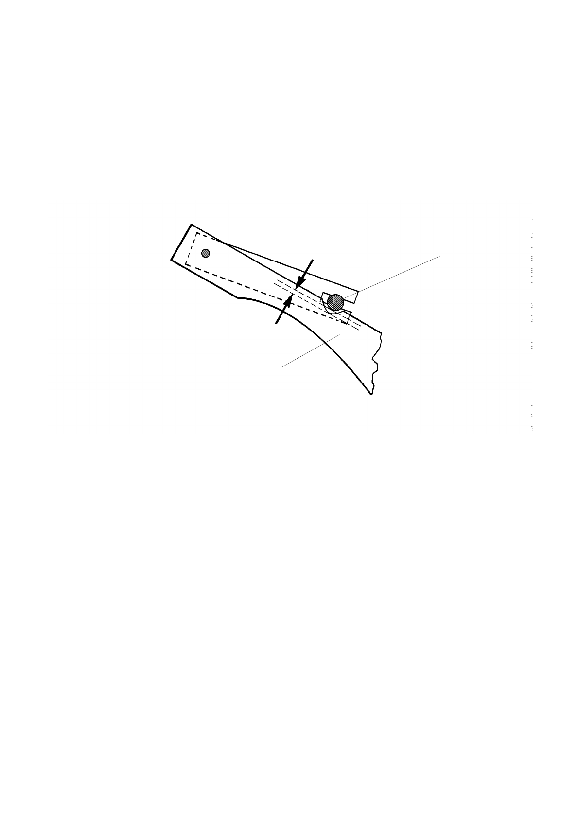
5. Move CASSETTE SUCKER BAR by hand on OPENER GAUGE 9193386 to a clearance of approx. 2.5 mm
between SUCKER BAR MOU NTS and the cutout of the SUCKER BAR CAMS. If necessary loosen STOP 1.
STOP 2
STOP 1
NUT
OPENER GAUGE
BEARING SHAFT
CASSETTE SUCKER BAR CAM
figure 28
6. Check that the SUCKERS are located between the two lines on OPENER GAUGE and that OPENER
GAUGE rests tightly at the CASSETTE STOP. If position of CASSETTE SUCKER BAR is not correct loosen
SCREW on BEARING SHAFT and adjust BEARING SHAFT. Check this adjustment by moving CASSETTE
SUCKER BAR in and out.
Note:
The CASSETTE SUCKER BAR CAMS must not hit OPENER GAUGE or FRAME of ML 700. It
may ride only on BEARING of BEARING SHAFT.
MA3053-9 24 KODAK AG Stuttgart
Page 25
7. Move the CASSETTE SUCKER BAR out by MOTOR: Press keys 8, 4, 2 (Option 7.4 "CASSETTE SUCKER
BAR BACK").
8. The DRIVE SH AF T should be stopped at a clearance of approx. 3 mm be t wee n CASSETTE SUCKER BAR
CAMS and DRIVE SHAFT.
DRIVE SHAFT
CASSETTE SUCKERBAR CAM
figure 29
9. If the BACK position of CASSETTE SUCKER BAR is not correct adjust SWITCH S12 (CSO). See figure 30.
KODAK AG Stuttgart 25 MA3053-9
Page 26
S12 (CSO)
CAM
SCREW
figure 30
MA3053-9 26 KODAK AG Stuttgart
Page 27

STOP 2
figure 31
STOP SCREW
DRIVE SHAFT CASSETTE SUCKER BAR
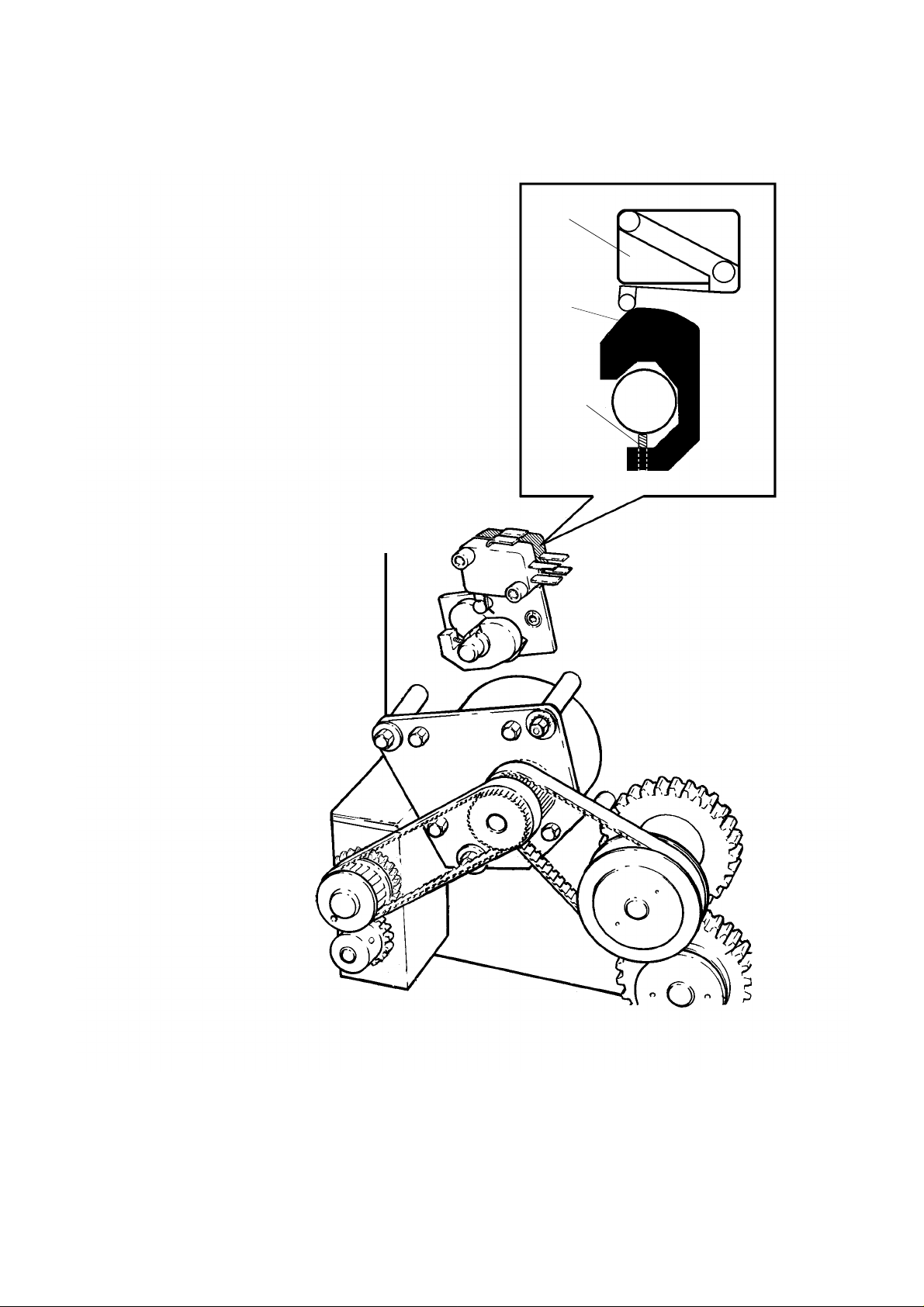
10. When SWITCH S12 (CSO) has actuated there should be a clearance of 1 mm between STOP SCR E W
an STOP 2. If necessary adjust STOP 2 .
11. Move CASSETTE SUCKER BAR in TAKE position: Press key 1.
12. The CASSETTE SUCKER BAR has to be placed on OPENER GAUGE 9193386 as shown on figure 29.
13. If the TAKE position of the CASSETTE SUCKER BAR is not correct perform the adjustments begining
on pa ge 29.
KODAK AG Stuttgart 27 MA3053-9
Page 28

The distance between ACTUATOR
and SWITCH must be always
above or equal 0.3 mm when the
SWITCH is actuated to avoid
damage to the SWITCH!
SWITCH S11 (csi)
a ≥ 0.3 mm
ACTUATOR
SCREW
CAM
figure 32
MA3053-9 28 KODAK AG Stuttgart
Page 29

If SOFTWARE version 2.14 is installed:
13.1. Adjust SWITCH S11 to actuate, when CASSETTE SUCKER BAR is in the correct position. Continue
with step 14.
If SOFTWARE Version 3.1 is installe d:
13.1. Move the CASSETTE SUCKER BAR on OPENER GAUGE 9193386 as shown on figure 28 by turning
the DRIVE SHAF T by hand. If necessary loosen STOP 1.
13.2. Key in 5 (CASSETTE SUCKER BAR BACK 100 MS USW).
13.3. Adjust CAM for SWITCH S11 (CSI) that SWIT CH S11 (CSI) just actuates tighten SCREW.
See figure 32.
Note:
Do not turn the DRIVE SHAFT.
14. Key in 2, 1 (BACK, TAKE) and check if CASSETTE SUCKER BAR is located on OPENER GAUGE as
shown on figure 28. If necessary readjust SWIT CH S 1 1 (CS I).
KODAK AG Stuttgart 29 MA3053-9
Page 30

15. When CASSETTE SUCKER BAR is located on OPENER GAUGE as shown in figure 28 there should be
a clearance of 2 mm between STOP SCREW an STOP 1.
DRIVE SHAFT CASSETTE SUCKERBAR
STOP SCREW
STOP 1
figure 33
2 mm
MA3053-9 30 KODAK AG Stuttgart
Page 31

KODAK AG Stuttgart 31 MA3053-9
Page 32

 Loading...