

Page 1
{Diagnostics}{Production}{He althImaging}
Publication No. 7C8290
28JAN98
HEALTH IMAGING
Kodak X-Omat
in a Kodak X-Omat
DIAGNOSTICS
for the
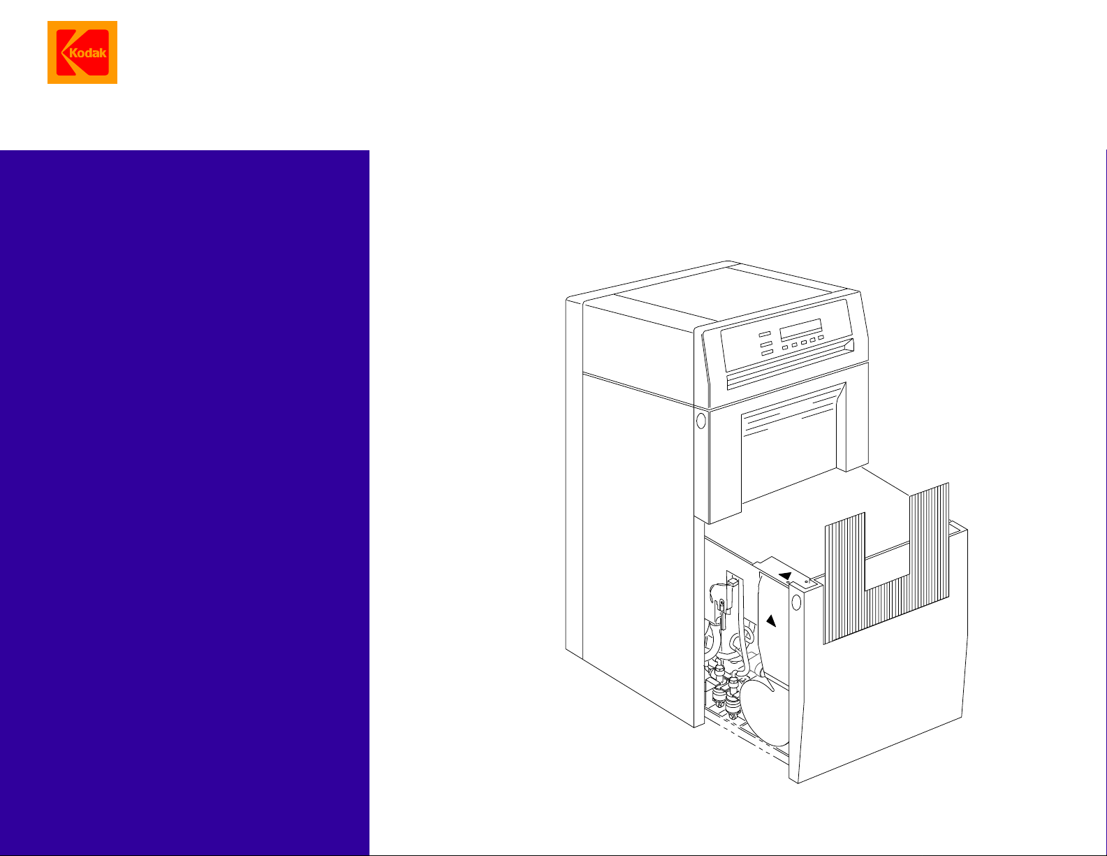
3000 RA INTEGRATED PROCESSOR
MULTILOADER 300 PLUS
© Eastman Kodak Company, 1999
Page 2

PLEASE NOTE The information contained herein is based on the experience and knowledge relating to the
subject matter gained by Eastman Kodak Company prior to publication.
No patent license is granted by this information.
Eastman Kodak Company reserves the right to change this information without notice, and
makes no warranty, express or implied, with respect to this information. Kodak shall not be liable
for any loss or damage, including consequential or special damages, resulting from any use of
this information, even if loss or damage is caused by Kodak’s negligence or other fault.
Table of Contents
Description Page
Error Codes . . . . . . . . . . . . . . . . . . . . . . . . . . . . . . . . . . . . . . . . . . . . . . . . . . . . . . . . . . . . 3
Introduction and Definitions . . . . . . . . . . . . . . . . . . . . . . . . . . . . . . . . . . . . . . . . . . . . 3
All Errors . . . . . . . . . . . . . . . . . . . . . . . . . . . . . . . . . . . . . . . . . . . . . . . . . . . . . . . . . . 3
Fatal Errors . . . . . . . . . . . . . . . . . . . . . . . . . . . . . . . . . . . . . . . . . . . . . . . . . . . . . . . . 4
Non-Fatal Errors. . . . . . . . . . . . . . . . . . . . . . . . . . . . . . . . . . . . . . . . . . . . . . . . . . . . . 5
Warnings . . . . . . . . . . . . . . . . . . . . . . . . . . . . . . . . . . . . . . . . . . . . . . . . . . . . . . . . . . 12
Mechanical Diagnostics . . . . . . . . . . . . . . . . . . . . . . . . . . . . . . . . . . . . . . . . . . . . . . . . . . 13
Transport Malfunction . . . . . . . . . . . . . . . . . . . . . . . . . . . . . . . . . . . . . . . . . . . . . . . . 13
Artifacts and Wrong Film Densities . . . . . . . . . . . . . . . . . . . . . . . . . . . . . . . . . . . . . . 14
Wet Films . . . . . . . . . . . . . . . . . . . . . . . . . . . . . . . . . . . . . . . . . . . . . . . . . . . . . . . . . . 16
Solution Levels. . . . . . . . . . . . . . . . . . . . . . . . . . . . . . . . . . . . . . . . . . . . . . . . . . . . . . 18
2 28JAN98 – 7C8290
Page 3

Error Codes
Section 1: Error Codes
Introduction and Definitions
Introduction • The 500 BOARD monitors the PROCESSOR functions during normal
operations, and continually checksforerrors. When an error occurs,anerror
code is displayed on the DISPLAY PANEL.
• Error codes are displayed by priority.
• The lower the error code number, the higher the priority.
• More than one error code can occur at one time.
• When 2 or more error codes occur, only the error code with the highest
priority will be displayed.
• When a high priority error code is corrected, the next priority error code is
displayed.
• All errors are stored in an error log on the 500 BOARD. Use a PORTABLE
COMPUTER and the correct software for access to the error log. The error
log records the number of times an error occurred.
• There are 3 types of error code: Fatal, Non-Fatal and Warning.
NOTE: When errors occur, the MICROPROCESSOR BOARD might disable
some components.
Use the PORTABLE COMPUTER and the diagnostic tests to analyze the
components.
Fatal Errors A Fatal Error indicates a problem which can cause a dangerous condition if the
PROCESSOR continues to operate. If a sheet of film is being processed when a
fatal error occurs, the film will exit the PROCESSOR. The PROCESSOR will
stop operating and no new films can be inserted into the PROCESSOR. If
additional sheets of film are inserted before the PROCESSOR stops operating,
the film will exit the PROCESSOR, then the PROCESSOR will stop operating
and no films canbe inserted. If aFatalError occurs when thePROCESSOR is in
the standby mode, the PROCESSOR will not operate and no films can be
inserted. The operator cannot correct Fatal Errors. The operator should move
BREAKER CB2, on the PROCESSOR, to the “off” or “O” position and make a
call for service.
Non-Fatal Errors A Non-Fatal Error will not prevent the PROCESSOR from operating. Filmcan be
inserted into the PROCESSOR, but the image quality might decrease. The
operator cannot correct most Non-Fatal errors.The operator should make a call
for service.
Warning Errors A Warning Error indicates a temporary condition or a problem which can be
corrected by the operator. The PROCESSOR will operate and films can be
inserted. Image quality might decrease.
All Errors
Important
When you check an electrical component or BOARD, also check all the:
• connections and CABLES for the component or BOARD
• voltages from the POWER SUPPLY for the component or BOARD
7C8290 – 28JAN98 3
Page 4
DIAGNOSTICS
Fatal Errors
Code Description Possible Malfunction Action
E001 500 BOARD Corrupted software on the 500
BOARD
E002 Dryer over maximum
temperature
Note
Themaximumtemperature
is 79 C (175 F).
Normally, the DRYER DC
OVER-TEMPERATURE
THERMOSTAT opens
beforetheDRYERreaches
this temperature.
E004 Inoperative transport See E041 in the Non-Fatal Errors Table.
E005 Dryer over-temperature
thermostat open
E006 Initialization
communication error
E007 Developer thermistor
failure
E008 Fixer thermistor failure The FIXER HEATER is disabled when this error occurs.
E009 Dryer thermistor failure The DRYER HEATER is disabled when this error occurs.
E010 Analog-to-digital converter
failure
DRYER THERMISTOR Check that the resistance at 25 C
SOLID STATE RELAY U3 that
controls the DRYER HEATER
500 BOARD Install a new BOARD.
When this error occurs, the DRYER HEATER and BLOWER are disabled.
CABLE between PROCESSOR
and MULTILOADER 500 BOARD
The DEVELOPER HEATER is disabled when this error occurs.
DEVELOPER THERMISTOR Install a new THERMISTOR.
FIXER THERMISTOR Install a new THERMISTOR.
DRYER THERMISTOR Install a new THERMISTOR.
All 3 HEATERS are disabled when this error occurs.
500 BOARD Install a new BOARD.
• Load the current software again.
or
• Install new PROMS/EEPROMS:
U17, U19, and U20 on the 500
BOARD.
(77 F) is approximately 10 KW.
Check SSR U3.
Allow THERMOSTAT to reset. If the
THERMOSTAT opens again, determine
the cause of the over-temperature
condition. See E002.
Install a new CABLE. Install a new
BOARD.
4 28JAN98 – 7C8290
Page 5
Non-Fatal Errors
Code Description Possible Malfunction Action
E032 Developer tank fill
error
This error will occur if the:
• DEVELOPER TANK:
– does not fill in 4 minutes in normal operation.
– does not fill in 15 minutes in the Tank Fill Mode.
– is empty and the operator does not select the Tank Fill Mode.
• REPLENISHER TANK is empty.
• REPLENISHMENT HOSE has an obstruction.
• TANKS of the PROCESSOR are filledwithwaterduringthe initial installation.
The following parts will be disabled:
• DEVELOPER REPLENISHMENT PUMP
• RECIRCULATION PUMP
• Temperature control for the fixer and developer
To prevent the error from occurring during the initial installation:
• add 240 mL (8 fl oz) of developer to the DEVELOPER TANK before you fill
the PROCESSOR with water.
• energize the RECIRCULATION PUMP to move the developer and remove
any air bubbles. Use the diagnostics to energize the PUMP.
LEVEL PROBES Clean and check the PROBES.
The solution level in the
REPLENISHER TANK is low.
Solution does not flow through the
HOSES between the
REPLENISHMENT TANK and the
REPLENISHMENT PUMP.
The DEVELOPER DRAIN VALVE
is open.
SOLID STATE RELAY SSR U2
that controls the DEVELOPER
REPLENISHMENT PUMP
POPPET VALVES in the
DEVELOPER REPLENISHMENT
PUMP
DEVELOPER REPLENISHMENT
PUMP
The500BOARDdoesnotenergize
the SOLID STATE RELAY
SSR U2.
Mix new developer solution.
Check:
• HOSE CLAMPS are tight
• HOSES:
– are round and opened
– have no obstructions or air bubbles
Close the VALVE.
Check SSR U2.
Clean and check the VALVES.
Check FUSE F1 and the
REPLENISHMENT PUMP MOTOR B3.
If necessary, install a new BOARD.
Error Codes
7C8290 – 28JAN98 5
Page 6

DIAGNOSTICS
Code Description Possible Malfunction Action
E033 Fixer tank fill error This error will occur if the:
• FIXER TANK
– does not fill in 4 minutes in normal operation.
– does not fill in 15 minutes in the Tank Fill Mode.
– is empty and the operator does not select the Tank Fill Mode.
• REPLENISHMENT TANK is empty.
• REPLENISHMENT HOSE has an obstruction.
• TANKS of the PROCESSORarefilled with water during theinitialinstallation.
The following parts will be disabled:
• FIXER REPLENISHMENT PUMP
• RECIRCULATION PUMP
• Temperature control for the fixer and developer
To prevent the error from occurring during the initial installation:
• add 240 mL (8 fl oz) of fixer to the FIXER TANK before you fill the
PROCESSOR with water.
• energize the RECIRCULATION PUMP tomove the fixer and removeany air
bubbles. Use the diagnostics to energize the PUMP.
LEVEL PROBES Clean and check the PROBES.
The solution level in the
Mix new fixer solution.
REPLENISHER TANK is low.
Solution does not flow through the
HOSES between the
REPLENISHMENT TANK and the
Check:
• HOSE CLAMPS are tight
• HOSES:
REPLENISHMENT PUMP.
– are round and opened
– have no obstructions or air bubbles
The FIXER DRAIN VALVE is open. Close the VALVE.
SOLID STATE RELAY SSR U4
Check SSR U4.
that controls the FIXER
REPLENISHMENT PUMP
POPPET VALVES in the FIXER
Clean and check the VALVES.
REPLENISHMENT PUMP
FIXER REPLENISHMENT PUMP Check FUSE F1 and the
REPLENISHMENT PUMP MOTOR B4.
The500BOARDdoesnotenergize
If necessary, install a new BOARD.
the SOLID STATE RELAY
SSR U4.
6 28JAN98 – 7C8290
Page 7

Code Description Possible Malfunction Action
E034 Unable to determine
developer temperature
The DEVELOPER HEATER and the DEVELOPER COOLING SOLENOID is
disabled when this error occurs.
DEVELOPER THERMISTOR:
• open•circuit or short•circuit
• Resistance not correct
• Check that the resistance at 25 C
(77 F) is approximately 10k ohms.
• If necessary, install a new
DEVELOPER THERMISTOR
500 BOARD:
Install a new 500 BOARD.
• A/D CONVERSION
ELECTRONICS malfunction
• PRECISION RESISTOR test
failure
Ambient temperature is below
15 C (59 F).
Increase the ambient temperature, or deenergize and then energize the
PROCESSOR.
See EO37 for additional actions.
E035 Unable to determine
fixer temperature
The FIXER HEATER is disabled when this error occurs.
FIXER THERMISTOR:
• open•circuit or short•circuit
• Resistance not correct
• Check that the resistance at 25 C
(77 F) is approximately 10k ohms.
• If necessary, install a new FIXER
THERMISTOR.
500 BOARD:
Install a new 500 BOARD.
• A/D CONVERSION
ELECTRONICS malfunction
• PRECISION RESISTOR test
failure
Ambient temperature is below
15 C (59 F).
Increase the ambient temperature, or deenergize and then energize the
PROCESSOR.
See EO39 for additional actions.
Error Codes
Code Description Possible Malfunction Action
E036 Unable to determine
DRYER temperature
The DRYER HEATER is disabled when this error occurs.
DRYER THERMISTOR:
• open•circuit or short•circuit
• Resistance not correct
• Check that the resistance at 25 C
(77 F) is approximately 10k ohms.
• If necessary, install a new DRYER
THERMISTOR
500 BOARD:
Install a new 500 BOARD.
• A/D CONVERSION
ELECTRONICS malfunction
• PRECISION RESISTOR test
failure
See EO40 for additional actions.
7C8290 – 28JAN98 7
Page 8

DIAGNOSTICS
Code Description Possible Malfunction Action
E037 Loss of developer heating
ability
DEVELOPER HEATER HR1 has an internal OVERTEMPATURE
THERMOSTAT. When the HEATER is too hot, the OVERTEMPERATURE
THERMOSTAT opens. Wait for the HEATER to cool and allow the
THERMOSTAT to reset before you measure the resistance.
SOLID STATE RELAY
U1(controls the DEVELOPER
HEATER)
DEVELOPER HEATER HR1:
• open•circuit
• Incorrect resistance
Check for correct operation of SOLID
STATE RELAY U1. If necessary, install a
new RELAY U1.
• Check FUSE F2.
• Check that the resistance at 25 C
(77 F) is approximately 50 ohms.
• Install a new DEVELOPER HEATER
HR1.
500 BOARD does not energize
Install a new 500 BOARD.
the SOLID STATERELAY U1:
Malfunction of RELAY K504A
DEVELOPER COOLING
SOLENOID L2
• Check that DEVELOPER COOLING
SOLENOID L2 stops the developer flow
through the HEAT EXCHANGER.
• If necessary, install anew DEVELOPER
COOLING SOLENOID L2.
RECIRCULATION PUMP • Check FUSE F1.
• Check for the correct operation of
MOTOR B5.
• If necessary, install a new
RECIRCULATION PUMP.
See EO34 for additional actions.
8 28JAN98 – 7C8290
Page 9

Code Description Possible Malfunction Action
E038 Loss of developer
cooling ability
Water does not enter the WASH
TANK.
Check:
• that water is supplied to the
PROCESSOR.
– The water supply is turned on.
– The FILTER is clean.
• WASH WATER SOLENOID L1
– The operation is correct.
– The SCREEN has no obstructions.
• DEVELOPER COOLING SOLENOID
L2
• QUICK DISCONNECT
The temperature of the water
entering the WASH TANK is too
hot.
Decrease the temperature of the water
supply. The wash water must be a
minimum of 5.5 C (10 F) below the
set•point of the developer.
HEAT EXCHANGER in the WASH
TANK
The 500 BOARD does not energize
SOLENOIDS L1 or L2
Remove any obstructions from the
EXCHANGER.
Check for 24 V DC at TERMINALS 1 and 2
on the:
• WASH WATER SOLENOID L1
• DEVELOPER COOLING SOLENOID
L2
If necessary, install a new BOARD.
RECIRCULATION PUMP Check the RECIRCULATION PUMP
MOTOR B5. If necessary, install a new
PUMP.
The WASH TANK CLIP is not fully
seated or is not installed.
Check that the CLIP is fully seated. If
necessary, install the CLIP.
Error Codes
7C8290 – 28JAN98 9
Page 10

DIAGNOSTICS
Code Description Possible Malfunction Action
E039 Loss of fixer heating ability FIXER HEATER HR2 has an internal OVERTEMPATURE THERMOSTAT.
When the HEATER is too hot, the OVERTEMPERATURE THERMOSTAT
opens. Wait for the HEATER to cool and allow the THERMOSTAT to reset
before you measure the resistance.
SOLID STATE RELAY U5
(controls the FIXER HEATER)
Check for correct operation of SOLID
STATE RELAY U5. If necessary, install a
new RELAY U5.
FIXER HEATER HR2:
• open•circuit
• Incorrect resistance
• Check FUSE F2.
• Check that the resistance at 25 C
(77 F) is approximately 50 ohms.
• Install a new FIXER HEATER HR2.
500 BOARD does not energize
Install a new 500 BOARD.
the SOLID STATERELAY U5:
Malfunction of RELAY K504B
RECIRCULATION PUMP • Check FUSE F1.
• Check for the correct operation of
MOTOR B5.
• If necessary, install a new
RECIRCULATION PUMP.
See EO35 for additional actions.
Code Description Possible Malfunction Action
E040 Loss of dryer heating ability A PANEL or DRYER RACK is
Install the part.
not installed.
SOLID STATE RELAYU3 that
Check SSR U3.
controls the DRYER HEATER
RELAY K1 that enables the
Check K1.
DRYER HEATER
No continuity for the DRYER
HEATER
DRYER
OVER-TEMPERATURE
THERMOSTAT
Check that the resistance at 25 C (77 F) is
approximately 16 W.
Allow the THERMOSTAT to reset. If the
THERMOSTAT opens again, determine the
cause of the high temperature. If you cannot
determine the causeof the problem, installa
new THERMOSTAT.
No continuity for the DRYER
HEATER THERMAL CUTOFF
500 BOARD:
Check that the DRYER BLOWER operates
correctly. Install a new CUTOFF.
If necessary, install a new BOARD.
• The 500 BOARD does not
energize the SOLID
STATE RELAY SSR U3.
• The RELAY K501
malfunctions.
10 28JAN98 – 7C8290
Page 11

Code Description Possible Malfunction Action
E041 Loss oftransportspeedcontrol
Note
This error occurs when the
transport speed is set for 10
seconds and the speed is not
within 7.6 cm/min (3 in./min) of
the set•point.
When the PROCESSOR operates normally:
• The supply voltage from the QUAD POWER SUPPLY through the
7000 BOARD to the DRIVE MOTOR CONTROLLER is 24 V DC at
PIN 3 on the DRIVE MOTOR CONTROLLER.
• The control voltage at Test Point 10 on the 500 BOARD is
approximately:
1.0 V DC for the Extended Speed
1.9 V DC for the Standard Speed
2.6 V DC for the Rapid Speed
3.4 V DC for the K/RA Speed
Note
There might be large variations in control voltages between
PROCESSORS.
Feedback pulses from the DRIVE MOTOR CONTROLLER at Test Point
8 on the 500 BOARD indicate the speed of the DRIVE MOTOR.
Error Codes
If the transport operates slower than the set speed, the
MICROPROCESSOR increases the control voltage approximately 25
mV every second at Test Point 8 on the 500 BOARD. When the voltage
reaches 5 V DC, the MICROPROCESSOR stops increasing the voltage.
500 BOARD If the control voltage is not correct at TP 10
on the 500 BOARD, install a new BOARD.
7000 BOARD Install the PROCESSOR in the
MULTILOADER and check for the following
voltages on the 7000 BOARD:
• 24 V DC between PINS 1 and 10 of
PJ7003
• 5 V DC between PINS 4 and 10 of
PJ7003
DC DRIVE MOTOR B6 or
DRIVE MOTOR
CONTROLLER
E042 Loss of accessory data link Loose connections Check all connections between any
500 BOARD Install a new BOARD.
2000 BOARD Install a new BOARD.
E045 Display data link error CABLES between the
3000 and 500 BOARD
If B6 operates, but no pulses occur at Test
Point 8 on the 500 BOARD, check:
• B6
• CONTROLLER
accessory and the PROCESSOR.
Check the CABLES.
7C8290 – 28JAN98 11
Page 12

DIAGNOSTICS
Warnings
Error
Code Error Description Possible Malfunction Action
E128 PROCESSOR is not
engaged in the
MULTILOADER
E129 Tanks currently being
filled
E130 Replenish pumps
disabled
E132 Developer under set
temperature
E133 Developer over set
temperature
E134 Dryer under set
temperature
E141 Low developer tank
level
E142 Low fixer tank level When this error occurs,
When this error occurs,
• the following function is disabled:
– film transport
• the following parts are disabled:
– DRYER HEATER
– BLOWER
PROCESSOR is extended. Engage the PROCESSOR in the MULTOLOADER.
INTERLOCK SWITCH S4 Check S4. If necessary, install a new S4.
7000 BOARD Install a new BOARD.
When this error occurs,
• the following function is disabled:
– film transport
• the following parts are disabled:
– RECIRCULATION PUMP
– 3 HEATERS
– DRYER BLOWER
None None. This message will clear automatically.
None Use the KEYPAD to select either Automatic or
Flooded Replenishment to enable the PUMPS.
None None. This message will clear automatically when
the developer reaches the set•point temperature.
None None. This message will clear automatically when
the developer reaches the set•point temperature.
None None. This message will clear automatically when
the DRYER reaches the set•point temperature.
When this error occurs,
• the RECIRCULATION PUMP is disabled.
• the temperature control for the fixer and developer is disabled.
None This error will clear automatically when the
developer solution reaches the correct level.
• the RECIRCULATION PUMP is disabled.
• the temperature control for the fixer and developer is disabled.
None This error clears automatically when the fixer
solution reaches the correct level.
12 28JAN98 – 7C8290
Page 13

Section 2: Mechanical Diagnostics
Transport Malfunction
Possible Cause Check
RACK and CROSSOVER
ASSEMBLIES
ROLLER ASSEMBLIES ROLLERS
DRYER AIR TUBE BAFFLES
RACK and CROSSOVER ASSEMBLIES:correct positionsseated
correctly
• squareness
– SeeADJUSTMENTSandREPLACEMENTS, Publication
No. 7C8285, RACKS and CROSSOVERS. Adjusting the
Squareness of the CROSSOVERS
Adjusting the Squareness of the RACKS
• cleaned completely
– SeethePREVENTIVEMAINTENANCE, Publication
No. 7C8289.
CROSSOVER TROUGHS
correct positions
WASH RESERVOIR
installed correctly
• correct positions
• rotate freely
• GUDGEONS
– no damage
– If necessary, install new ROLLERS.
GEARS, SPROCKETS, and IDLERS
• engage correctly
• not broken or worn
BEARINGS
no wear
SPRINGS and E-RINGS
not broken or missing
RACK ASSEMBLY
• DRIVE CHAIN
– tension
installed
Temperature setting of the DRYER
lowest possible setting to provide the best image quality
DRYER RACK
seated correctly
LOCKING TABS
correct positions
DRIVE GEAR on the DRYER RACK
no damage
Mechanical Diagnostics
7C8290 – 28JAN98 13
Page 14

DIAGNOSTICS
Artifacts and Wrong Film Densities
Possible Cause Check
Replenishment system Replenishment rates
correct setting
HOSES
• opened and round
• no obstructions
or air bubbles
HOSE CLAMPS
• tight
REPLENISHMENT PUMP
• operation
• calibration
Replenishment chemicals
• Change any chemicals that are:
– not mixed correctly
– exhausted
– contaminated
Note
When you mix chemicals:
• Mix a maximum of a 2-week supply of the DEVELOPER
RELENISHER.
• Follow all directions for mixing chemicals and solutions.
• Use a SPLASH GUARD and DRIP TRAY when you remove the
FIXER RACK from thePROCESSOR to prevent contamination ofthe
developer.
DEVELOPER and FIXER TANKS
• DRAIN VALVES
– completely closed
Recirculation system DEVELOPER and RECIRCULATION HOSES
• ORIFICES
– no obstructions
DEVELOPER FILTER
If necessary, install a new FILTER.
Movement of the solutions at the surface of the PROCESSOR TANKS
when you energize the PROCESSOR and the TANKS are full.
• If the solutions do not move, check:
– HOSES have no obstructions or air bubbles in the recirculation
system.
– RECIRCULATION PUMP operates.
– DEVELOPER FILTER is clean and in the correct position.
14 28JAN98 – 7C8290
Page 15

Possible Cause Check
RACK and CROSSOVER
ASSEMBLIES
RACKS and CROSSOVERS
• correct positions
• seated correctly
• cleaned completely
– SeethePREVENTIVEMAINTENANCE, Publication
No. 7C8289.
CROSSOVER TROUGHS and EVAPORATION COVERS
• correct positions
• TROUGHS
– clean
• TROUGH DRAINS
– no obstructions
WASH RESERVOIR
installed correctly
ROLLERS ROLLERS
• clean and not scratched
• correct positions
• rotate freely
• GUDGEONS
– no damage
– If necessary, install new ROLLERS.
DETECTOR ROLLERS
clean
GEARS, SPROCKETS, and IDLERS
• engage correctly
• no wear
BEARINGS
no wear
SPRINGS and E-RINGS
not broken or missing
DEVELOPER and FIXER RACK ASSEMBLIES
• DRIVE CHAINS
– correct adjustment of the tension
Drying system DRYER AIR TUBES
• clean
– If necessary, use a BOTTLE BRUSH and water to clean the
TUBES and SLOTS in the TUBES.
• BAFFLES
– installed
Temperature setting of the DRYER
• lowest possible setting to provide the best image quality
• exhaust for the PROCESSOR
– meets the specifications
– See the MULTILOADER 300 PLUS SITE SPECIFICATIONS.
Mechanical Diagnostics
7C8290 – 28JAN98 15
Page 16

DIAGNOSTICS
Possible Cause Check
Wrong water temperature Temperature of the water
Should be: 6.7 C (12 F) below the developer set point
Wash water Water flows through the WASH RACK
Holes in the WASH RESERVOIR
• clean
Ventilation system Exhaust for the PROCESSOR
• meets specifications
• See the MULTILOADER 300 PLUS SITE SPECIFICATIONS.
External EXHAUST HOSE
connected to the AIR EXHAUST
Internal EXHAUST HOSE
connected to the AIR EXHAUST
Wet Films
Possible Cause Check
Film and chemicals are not
compatible
Replenishment system Replenishment rates
Film
• compatible with selected system
• correct setting
HOSES
• opened and round
• no obstructions
HOSE CLAMPS
• tight
REPLENISHMENT PUMP
• operation
• calibration
Replenishment chemicals
• Change any chemicals that are:
– not mixed correctly
– exhausted
– contaminated
Note
When you mix chemicals:
• Mix a maximum of a 2-week supply of the DEVELOPER
RELENISHER.
• Follow all directions for mixing chemicals and solutions.
• Use a SPLASH GUARD and DRIP TRAY when you remove the
FIXER RACK from thePROCESSOR to prevent contamination ofthe
developer.
DEVELOPER and FIXER TANKS
• DRAIN VALVES
– completely closed
16 28JAN98 – 7C8290
Page 17

Mechanical Diagnostics
Possible Cause Check
Recirculation system Movement of the solutions at the surface of the PROCESSOR TANKS
when you energize the PROCESSOR and the TANKS are full.
• If the solutions do not move, check:
– HOSES have no obstructions or air bubbles in the recirculation
system
– RECIRCULATION PUMP operates
– DEVELOPER FILTER is clean and in the correct position
Drying system DRYER AIR TUBES
• clean
– If necessary, use a BOTTLE BRUSH and water to clean the
TUBES and SLOTS in the TUBES.
• BAFFLES
– installed
DRYER
• lowest possible setting to provide the best image quality
DRYER AIR EXHAUST
• no obstructions
• installed correctly
– See the Installation Instructions, Publication No. 5B9330.
DRYER HEATER
• operates correctly
DRYER RACK
• seated correctly
Wash water Water flows through the WASH RACK
Holes in the WASH RESERVOIR
• opened
– If necessary, clean theholes to prevent an overflowof water from
the TROUGHS into the DEVELOPER and FIXER TANKS.
7C8290 – 28JAN98 17
Page 18

Solution Levels
Possible Cause Check
Replenishment system Replenishment rates
• correct setting
HOSES
• opened and round
• no obstructions
REPLENISHMENT PUMP
• operation
• calibration
REPLENISHMENT TANKS
• quantity of solution
POPPET VALVES
• clean
• no damage
DEVELOPER and FIXER TANKS
• DRAIN VALVES
– no leakage
CROSSOVER TROUGHS
• correct position
• TROUGHS
– clean
• TROUGH DRAINS
– no obstructions
Mechanical Diagnostics
Publication History
Affected
Print Date Pub No. ECO No.
Jan. 98 7C8290 N/A All dg3488_1_28jan98.fm First Printing.
Pages File Name Notes
Kodak
and
X-Omat
are trademarks.
Printed in U.S.A. • dg3488_1.fm
EASTMAN KODAK COMPANY
Rochester, NY 14650
HEALTH IMAGING
 Loading...