

Page 1
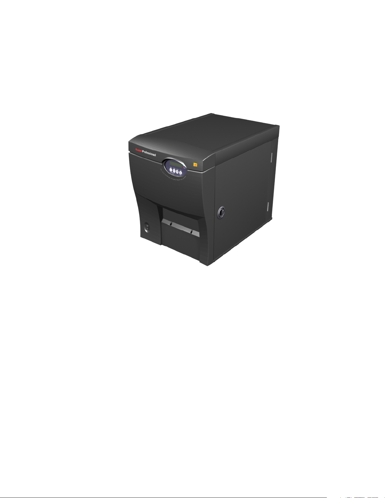
KODAK PROFESSIONAL ML-500
Digital Photo Print System
Operator Guide
Page 2

EASTMAN KODAK COMPANY
Kodak Professional Division
Rochester, New York 14650
© Eastman Kodak Company, 2002.
TM/MC/MR: Kodak, Kodak Professional,
Ektatherm and Xtralife are trademarks
www.kodak.com/go/professional
P/N 2J7852 3/02
Page 3
Safety and Regulatory Information
Mechanical hazard; moving parts. Keep fingers, hands, hair, jewelry, and loose articles of
clothing away from the path of the media through the printer.
April 2002 iii
Page 4
Regulatory Approval Requirements
Requirement Approval
EMISSION 47CFR15 Class A (FCC)
EN55022 Class A
AS/NZS 3548 Class A
ICES-003 Class A
VCCI Class A
BSMI CNS 13438) Class A
IEC 61000-3-2, 3-3
IMMUNITY EN61000-4-2
EN61000-4-3
EN61000-4-4
EN61000-4-5
EN61000-4-6
EN61000-4-11
iv April 2002
Page 5
European Community Statement
This equipment complies with the following European Directives:
EMC Directive 89/336/EEC and amending Directives 92/31/EEC and 93/68/
EEC Low Voltage Directives 73/23/EEC.
Warning Notice:
This is a Class A product. In a domestic environment this product may cause
radio interference in which case the user may be required to take adequate
measures.
FCC Class A Statement
This equipment has been tested and found to comply with the limits for a
Class A digital device, pursuant to part 15 of the FCC rules.
These limits are designed to provide reasonable protection against harmful
interference when the equipment is operated in a commercial environment.
This equipment generates, uses and can radiate radio frequency energy and,
if not installed and used in accordance with the instruction manual, may
cause harmful interference to radio communications.
Operation of this equipment in a residential area is likely to cause harmful
interference in which case the user will be required to correct the
interference at his own expense.
VCCI Statement (Japan)
English translation:
This is a Class A product. A product based on the standard of the Voluntary
Control Council for interference by Information Technology Equipment
(VCCI). If this equipment is used in a domestic environment, radio
disturbance may arise. When such trouble occurs, the user may be required
to take corrective actions.
April 2002 v
Page 6
BSMI Statement (Taiwan)
English translation:
This is a Class A product. In a domestic environment this product may cause
radio interference in which case the user may be required to take adequate
measures.
vi April 2002
Page 7

Table of Contents
1 Product Overview
Introduction..................................................................................................................................................... 1-1
2 Setting up the Printer
Determining a Location....................................................................................................................................2-1
Unpacking the Printer ...................................................................................................................................... 2-2
Lifting and Moving the Printer ....................................................................................................................2-3
Handling and Storing Media ............................................................................................................................. 2-4
Loading the Ribbon ..........................................................................................................................................2-5
Loading the Paper ............................................................................................................................................2-7
Attaching the Print Catcher ..............................................................................................................................2-8
Connecting the Cables ......................................................................................................................................2-9
Turning on the Printer ..................................................................................................................................... 2-9
Making a Test Print ........................................................................................................................................2-10
Installing the Software....................................................................................................................................2-10
3 Operating the Printer
Operator Control Panel Overview .....................................................................................................................3-1
Display Messages .......................................................................................................................................3-2
Status and Error Indicator..........................................................................................................................3-2
Buttons ...................................................................................................................................................... 3-3
Changing Printer Settings .................................................................................................................................3-4
Handling and Storing Prints .............................................................................................................................3-5
4 Troubleshooting
Error Messages ................................................................................................................................................ 4-1
Warnings ................................................................................................................................................... 4-1
User Correctable Errors .............................................................................................................................4-2
Service Error..............................................................................................................................................4-3
Image Quality Problems .............................................................................................................................4-4
Recovering from Power Interruption.......................................................................................................... 4-5
Clearing Paper Jams......................................................................................................................................... 4-6
Clearing Ribbon Jams.......................................................................................................................................4-6
Repairing Damaged Ribbon .............................................................................................................................4-7
Customer Support and Technical Assistance.....................................................................................................4-8
April 2002 vii
Page 8

Table of Contents
5 Maintaining the Printer
Cleaning the Printer .........................................................................................................................................5-1
Replacing the Air Filter.....................................................................................................................................5-1
Appendix A: Site Specifications
Printer Specifications .......................................................................................................................................A-1
Space Requirements.........................................................................................................................................A-2
Operating Environment ....................................................................................................................................A-2
Power Requirements ..................................................................................................................................A-2
Appendix B: Accessories and Supplies
Appendix C: System Requirements
PC Server Requirements ...................................................................................................................................C-1
Client System Requirements .............................................................................................................................C-2
PC Client System .........................................................................................................................................C-2
MACINTOSH Client System..........................................................................................................................C-3
viii April 2002
Page 9
1
Product Overview
Introduction
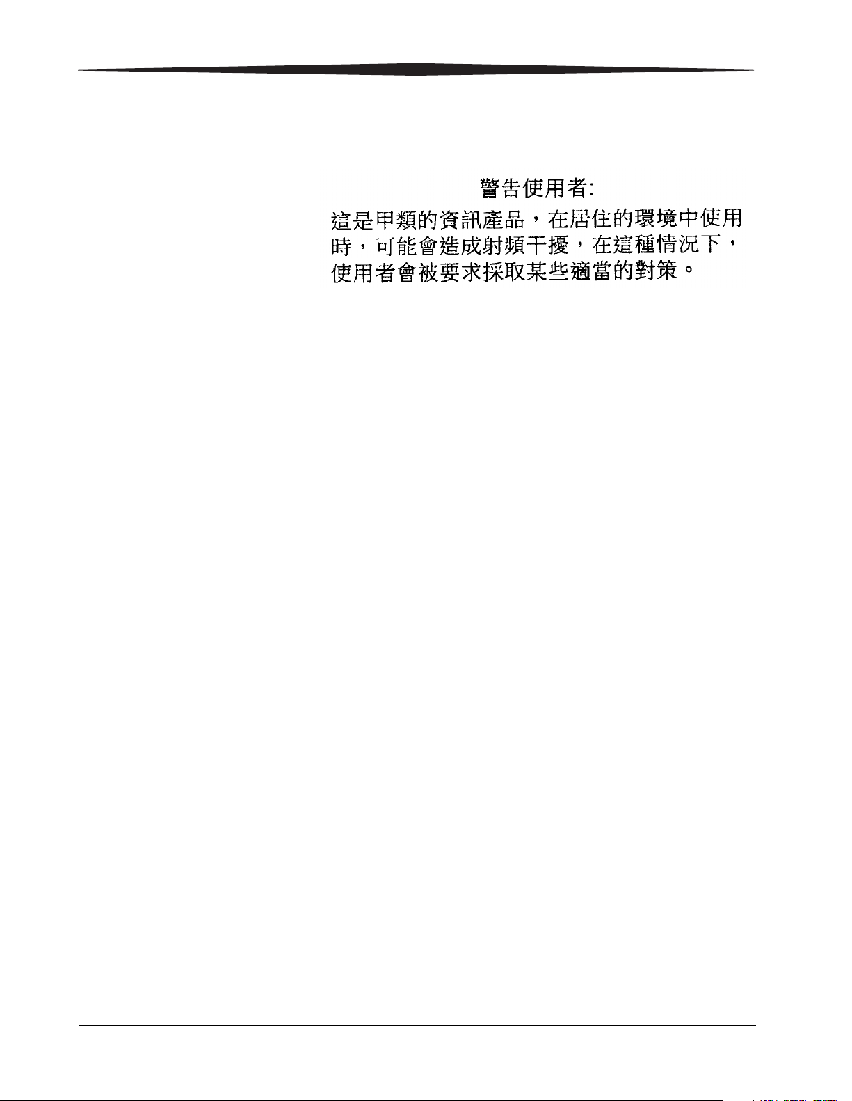
The KODAK PROFESSIONAL ML-500 Digital Photo Print System is a 4-head
continuous-feed, thermal dye diffusion printer designed to produce
professional quality photo images quickly. The system plugs into existing
workflows, whatever the application -- in the studio, lab, or on location. It has
a compact design and its completely dry thermal imaging system makes it
easy to transport.
The ML-500 system includes the ML-500 Printer, PCI compatible IEEE1394A
data interface card and cable, utilities software, and print drivers. In addition,
a CD containing the utilities software, print drivers, and an on-line operators
guide with animation is provided for setup and operation.
3
3
4
5
4
56
Back View
1. Media Loading Instructions
2. Operator Control Panel
3. Filter
4. IEEE 1394A cable connection
5. Power cable connection
6. Power switch
7. Print catcher assembly
7
2
2
6
7
Front View
1
1
April 2002 1-1
Page 10

Page 11

2
Setting up the Printer
Determining a Location
As you look for an appropriate location for your KODAK PROFESSIONAL
ML-500 Digital Photo Print System consider the following:
• The support surface must hold a minimum of 150 lbs (68.0 kg).
• The printer should not extend beyond the edge of the support surface.
• Allow 4 in.(10.2 cm)of unrestricted air flow on all sides of the printer.
NOTE: See Space Requirements, page A-2.
IMPORTANT: Avoid placing the printer where ventilation ducts, open
doors, or frequent passers-by might expose it to debris.
Airborne dirt particles can cause image quality problems.
April 2002 2-1
Page 12
Setting up the Printer
Unpacking the Printer
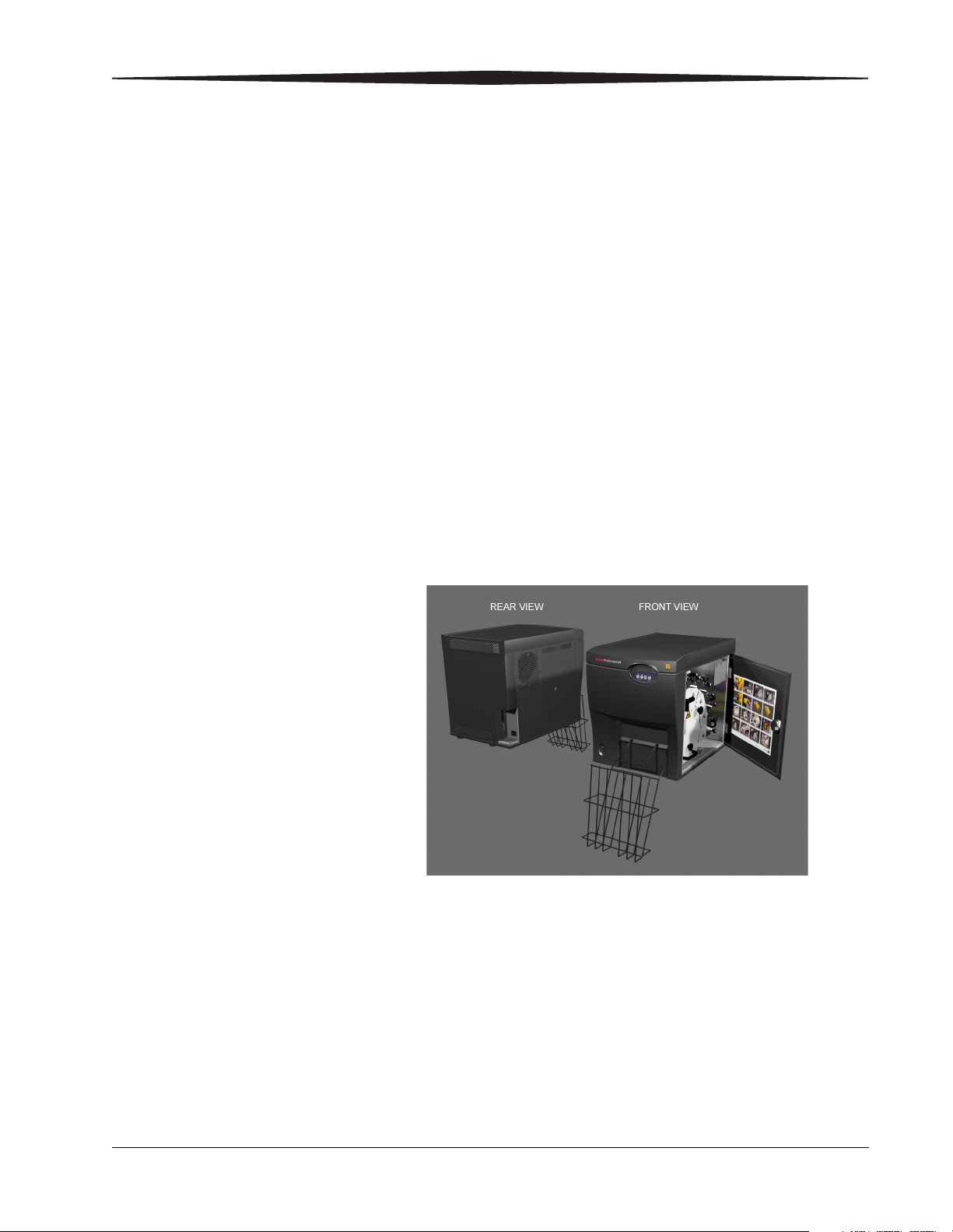
The following items are packaged with the printer.
NOTE: If any of these items are missing, contact your dealer or distributor.
Digital Photo Printer
Print Catcher Assembly
IEEE 1394A Cable
IEEE 1394A PC Interface Card
Power Cables
CD Software and Documentation Kit
Quick Setup Guide
Items
To unpack the printer:
1. Cut and remove the straps.
2. Remove the box.
3. Remove all components, foam caps, and the plastic bag.
2-2 April 2002
Page 13
Lifting and Moving the Printer
Setting up the Printer
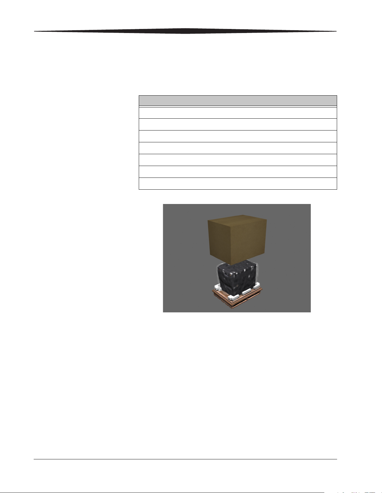
WARNING:
The printer weighs 120 lbs (54.4 kg). Use two people to lift
and carry it. Do not lift the printer from the front or back.
Grasp the printer along both sides, then move it to its location.
April 2002 2-3
Page 14

Setting up the Printer
Handling and Storing Media
• Do not expose the ribbon to direct sunlight, extreme heat, dust, or liquids.
• Do not use wet or damaged paper roll.
• Avoid placing fingerprints on the paper roll.
• Keep partially used ribbons and paper in their original wrappers to protect
them from dust and dirt when they are not loaded in the ML-500 printer.
Dust and dirt specks on the ribbon appear as much larger spots on prints.
• Store the unopened ribbon and paper at temperatures below 77°F (25°C).
• Avoid exposure to temperatures higher than 100°F (38°C).
NOTE: Images remain on the ribbon after printing. If you are working with
confidential documents, you should consider alternate ways of
ribbon disposal to maintain security.
2-4 April 2002
Page 15

Loading the Ribbon
IMPORTANT: For the correct orientation and location of each ribbon
1. Open the printer door.
2. Turn the paper drawer locking knob counterclockwise several times,
NOTE: Use the ribbon holder, when loading the ribbon.
3. Grasp the ring handle on the yellow ribbon module and carefully remove
Setting up the Printer
CAUTION:
Use only ribbon designed for the ML-500 digital photo print
system. Using other materials may cause problems.
module, see Media Loading Instructions on the CD or inside
the printer door.
then pull the drawer outward until it locks into position.
the ribbon module from the printer.
4. Hang the ribbon module on the ribbon holder.
5. Align the notched end of the ribbon supply spool to the pins in the ribbon
module. Make sure the drive pin fits into the notched openings.
6. While holding the yellow ribbon supply spool in place, pull the knob with
the color-coded sticker outward until the end of the ribbon supply spool
can fit over the hub, then release the knob.
7. Grasp the take-up spool, and pull it around the bottom of the ribbon
module.
8. Attach the notched end of the yellow ribbon take-up spool into the
ribbon module. Make sure the drive pin fits into one of the notched
openings.
9. While holding the ribbon take-up spool in place, pull the knob without
the color-coded sticker outward until the end of the ribbon take-up
spool can fit over the hub, then release the knob.
10. Remove the yellow ribbon module from the ribbon holder.
11. Rotate the ribbon take-up coupling clockwise to remove the slack and
tension on the ribbon.
12. Grasp the ring handle located on the front surface of the yellow ribbon
module, then grasp the opposite end of the yellow ribbon module.
Carefully align the recessed channel on the yellow ribbon module to the
extended guide rail on the printer.
13. Slide the ribbon module into the printer.
14. Turn the ribbon take-up spool counterclockwise to tighten the web.
15. Repeat steps 3-14 for the magenta, cyan, and laminate ribbons.
April 2002 2-5
Page 16

Setting up the Printer
16. Release both drawer latches to slide the drawer into the printer about 1
inch (2.54 cm).
17. Turn the paper roll tension knob clockwise until the web is completely
snug, then push the drawer into the printer while holding the knob.
18. Turn the paper drawer locking knob clockwise several times until tight.
19. Close the printer door.
2-6 April 2002
Page 17

Loading the Paper
Setting up the Printer
CAUTION:
Use only paper designed for the ML-500 digital photo print
system. Using other materials may cause problems.
IMPORTANT: For the correct orientation and location of the paper roll,
see Media Loading Instructions on the CD or inside the
printer door.
1. Open the printer door.
2. Turn the paper drawer locking knob counterclockwise several times,
then pull the drawer outward until it locks into position.
3. Grasp the paper roll with the leading edge over the top of the roll facing
away from you.
4. Set the paper roll into the drawer on the guide rails.
5. Turn the pressure roller lever counterclockwise to fit the paper between
the pressure roller and the drive roller.
6. Wrap the leading edge of the paper roll around the four rubber rollers.
Make sure the paper is not under the metal drawer slide.
7. Position the leading edge of the paper between the pressure roller and
the drive roller.
8. Align the sides of the paper with the guide marks on the paper alignment
plates.
9. Turn the pressure roller lever clockwise to clamp the paper into position.
10. Turn the drive roller knob clockwise to position the leading edge of the
paper to the front edge of the alignment plate.
11. Turn the paper roll tension knob clockwise to remove the slack.
12. Turn each ribbon take-up spool counterclockwise on all four ribbon
modules until tight.
13. Release both drawer latches to slide the drawer into the printer about 1
inch (2.54 cm).
14. Turn the paper roll tension knob clockwise until the web is completely
snug, then push the drawer into the printer while holding the knob.
15. Turn the paper drawer locking knob clockwise several times until tight.
16. Close the printer door.
April 2002 2-7
Page 18

Setting up the Printer
Attaching the Print Catcher
1
2
1. Insert the print deflector into the two holes on the front cover.
2. Attach the print catcher to the print deflector.
2-8 April 2002
Page 19

Connecting the Cables
1. Plug the power cable into the printer, then into the outlet. See Power
Requirements, page A-2.
2. Plug one end of the IEEE 1394A cable into the printer, and the other end
into the IEEE 1394A port on your computer.
Turning on the Printer
Turn the power switch to the ON position (I).
The printer starts and performs a self-check for about one minute.
INITIALIZING appears on the display during the self-check. After the selfcheck has completed, READY appears on the display and the STATUS indicator
appears green.
If the system fails to start up, see Troubleshooting, page 4-1.
Setting up the Printer
April 2002 2-9
Page 20

Setting up the Printer
Making a Test Print
You can make a test print when READY appears on the display.
• To use the last test print pattern selected, press PRINT on the Operator
Control Panel.
• To change the test print pattern, press SETUP >Configuration >Test Print >
Pattern. PRINTING appears on the display panel while the image is
printing.
Installing the Software
1. Insert the CD shipped with the printer into the computer CD-ROM drive.
2. Follow the on-screen instructions to install the software and view the
documentation.
2-10 April 2002
Page 21

3
Operating the Printer
Operator Control Panel Overview
3
1. Display
2. Status and Error indicators
3. Buttons
1
2
April 2002 3-1
Page 22

Operating the Printer
Display Messages The panel displays two lines of messages:
• The printer state appears on the top line.
• The warnings or errors appear on the bottom line.
Status and Error Indicator
Indicator Color Status
STATUS Green On, when the printer completes its self check.
ERROR Red On, when service errors occur.
There are two Indicators on the Operator Control Panel:
STATUS and ERROR.
Flashes, when it is operating under caution. See Warnings,
page 4-1.
Flashes when a user correctable error occurs.
If a service error message appears on the display, turn the
Printer off and then back on.
If the message persists, service is required. See Customer
Support and Technical Assistance, page 4-8.
3-2 April 2002
Page 23

Operating the Printer
Buttons The following table describes the Operator Control Panel buttons.
Button Printer State Function
PRINT READY Makes a test print.
SETUP Scrolls up through the submenu.
CANCEL READY Actuates the cutter one time.
PRINTING Cancels all jobs.
SETUP Scrolls down through the submenu.
SELECT READY Push and hold to advance the paper, then release to stop.
SETUP Selects the currently displayed submenu or value when
navigating through the SETUP menu.
SETUP READY Enters the SETUP menu.
SETUP Exits the current submenu, return to the previous submenu,
or exit the SETUP menu.
April 2002 3-3
Page 24

Operating the Printer
Changing Printer Settings
You can view and change printer settings using the printer’s SETUP Mode. For
example, to change the language:
1. Press SETUP when READY appears on the display.
2. Press PRINT to scroll up (or CANCEL to scroll down) until
CONFIGURATION is displayed on the bottom line.
3. Press SELECT to access the configuration submenu.
4. Press PRINT to scroll up (or CANCEL to scroll down) until
CONFIGURATION is displayed on the top line and the languages are
displayed on the bottom line.
5. Press SELECT to access the language options.
6. Press PRINT to scroll up (or CANCEL to scroll down) until the selected
language is displayed on the bottom line.
7. Press SELECT to choose the language.
8. Repeatedly, press SETUP until the READY appears on the top line of the
display.
SETUP Mode Submenu Options Menu
CONFIGURATION Test Print
Language
STATUS Version Logs
User Logs
Service Logs
Pattern, Counts
English, German, French, Spanish, Italian
3-4 April 2002
Page 25

Handling and Storing Prints
Print image stability depends upon temperature, relative humidity, exposure,
light intensity, and biological or chemical contaminants. Using KODAK
PROFESSIONAL EKTATHERM XTRALIFE Ribbon increases the stability and
durability of your prints.
• Remove prints from the exit area ONLY AFTER the ML-500 printer ejects
them.
• Avoid storing prints at temperatures higher than 72°F (22°C) for extended
periods.
• Avoid exposure to sunlight.
Operating the Printer
April 2002 3-5
Page 26

Page 27

4
Troubleshooting
Error Messages
Error messages are displayed on the bottom line of the Operator Control
Panel and indicate that a problem has occurred. Warnings and usercorrectable errors appear as messages, and service errors appear as
numbers.
Warnings The STATUS indicator flashes while the ERROR indicator is off.
Message Cause Solution
PAPER LOW Approaching the end of the paper roll. Printing can continue. Check the paper supply and replace as
needed.
RIBBON LOW One or more of the ribbons are low. When the printer stops printing, determine which ribbons are
low and replace as needed.
YELLOW LOW YELLOW ribbon supply is low. Printing can continue. Check the yellow ribbon and replace as
needed.
MAGENTA LOW MAGENTA ribbon supply is low. Printing can continue. Check the magenta ribbon and replace as
needed.
CYAN LOW CYAN ribbon supply is low. Printing can continue. Check the cyan ribbon and replace as
needed.
XTRALIFE LOW XTRALIFE ribbon supply is low. Printing can continue. Check the XTRALIFE ribbon and replace
as needed.
COOLING The printer is too hot and is cooling
down.
Wait for the printer to cool down, then continue with printing.
April 2002 4-1
Page 28

Troubleshooting
User Correctable
The ERROR indicator flashes.
Errors
Message Cause Solution
PAPER EMPTY Paper is empty. Load a new paper roll.
YELLOW EMPTY Yellow ribbon is empty. Load a new yellow ribbon.
MAGENTA EMPTY Magenta ribbon is empty. Load a new magenta ribbon.
CYAN EMPTY Cyan ribbon is empty. Load a new cyan ribbon.
XTRALIFE EMPTY XTRALIFE ribbon is empty. Load a new XTRALIFE ribbon.
DOOR OPEN The printer door is open. Close the door.
DRAWER REMOVED The printer drawer is pulled out. Insert and lock the paper drawer.
PAPER JAM The paper is jammed inside of the printer. See Clearing Paper Jams, page 4-6 .
4-2 April 2002
Page 29

Troubleshooting
Service Error The STATUS indicator is off while the ERROR indicator is on.
Number Cause Solution
ERROR 700, 800 or 900
series
Service error 700, 800, or 900
has occurred
Turn the printer off for a few seconds, then back on.
If the message persists, service is required.
See Customer Support and Technical Assistance, page 4-8 .
April 2002 4-3
Page 30

Troubleshooting
Image Quality Problems
Problems Cause Solution
White and multi-colored spots Dirt or dust has caused contamination. Handle paper and ribbon carefully. See
Handling and Storing Media, page 2-4 .
Clean the printer and surrounding area.
Make sure the operating environment is
clean and dust free.
Move the printer away from room
ventilation ducts or open doors.
White lines and scratches Dirt or dust has caused contamination. Check that the paper roll is clean and
streak free.
Check that the ribbon is clean.
If the problem persists, service is required.
See Customer Support and Technical
Assistance, page 4-8 .
Smudges, smears, and fingerprints Fingerprints or other oils have caused
contamination.
Image is not centered on paper Paper may not be aligned properly.
Center Image was not selected in the Print
Server.
Black text has color fringe Print head may need adjustment. Refer to the on-line Help in the Printer
Cuts are not centered between prints Paper cutter may need adjustment. Refer to the on-line Help in the Printer
Handle paper and ribbon carefully. See
Handling and Storing Media, page 2-4 .
See Loading the Paper, page 2-7 .
Refer to the on-line Help in the Printer
Utilities > Print Server Application.
Utilities > Configuration Application.
Utilities > Configuration Application.
4-4 April 2002
Page 31

Recovering from Power Interruption
Troubleshooting
CAUTION:
If a power interruption occurs when printing, the printer will
stop with the thermal heads in the printing position.
Attempting to pull out the paper drawer assembly and ribbon
modules can damage the printer.
1. Keep the paper drawer assembly locked and in position.
2. Close the side door.
3. Make sure the power switch is in the on ( I ) position.
4. Let the printer initialize completely.
5. Follow the Media Loading Instructions inside the printer door.
If the paper drawer does not slide out easily, contact Kodak Customer
Support. See page 4-8.
April 2002 4-5
Page 32

Troubleshooting
Clearing Paper Jams
1. Make sure the power switch is in the on ( I ) position and the printer
2. Press the CANCEL button.
3. Let the printer initialize completely.
4. Press CANCEL to operate the cutter, if necessary.
5. Open the printer door.
6. Turn the pressure roller lever counterclockwise to release the paper.
7. Turn the paper roll tension knob clockwise to wind up the paper.
8. Turn the paper drawer knob counterclockwise several times until you
9. Grasp the drawer handle, and pull it outward until it locks into position.
10. Remove and inspect the paper roll. Replace the paper roll if necessary.
door is closed.
can pull the drawer out from the printer.
11. Load the paper roll. See Loading the Paper, page 2-7 .
If the paper jam cannot be cleared, contact Kodak Customer Support. See
page 4-8.
Clearing Ribbon Jams
1. Follow the instruction for Clearing Paper Jams steps 1-9 to access the
ribbon modules.
2. With the drawer open outward in its locked position, remove the ribbon
modules.
3. To load ribbon back into the printer, see Loading the Ribbon, page 2-5 .
4. To load paper back into the printer, see Loading the Paper, page 2-7 .
If the ribbon jam cannot be cleared, contact Kodak Customer Support. See
page 4-8.
4-6 April 2002
Page 33

Repairing Damaged Ribbon
1. Follow the instruction for Clearing Paper Jams steps 1-9 to access the
ribbon modules.
2. Remove the ribbon module.
3. Place the ribbon module onto the ribbon holder.
4. Remove the take-up spool and the supply spool from the ribbon module.
5. Place the take-up and supply spools on a flat surface.
6. Cut away the damaged ribbon edges.
7. Align the ribbon edges.
8. Using tape, connect the separated ends.
9. Load ribbon back into the printer, see Loading the Ribbon, page 2-5 .
NOTE: Make sure to wind the taped portion of the ribbon onto the take-up
spool before making prints.
Troubleshooting
April 2002 4-7
Page 34

Troubleshooting
Customer Support and Technical Assistance
Kodak Support in the U.S. and Canada.
For help in the U.S. and Canada, call 1-800-23KODAK, between 9:00 am and
8:00 pm. Eastern Standard Time on regular business days.
In addition, you may also obtain information from our Web sites:
• Kodak Professional home page: www.kodak.com/go/professional
• Kodak Environmental Services home page: www.kodak.com/go/kes
Kodak Support Centers Outside the U.S. and Canada.
For help outside the U.S. and Canada, see the following Web site:
• International Telephone Support Numbers: www.kodak.com/include/
international.shtml
4-8 April 2002
Page 35

5
Maintaining the Printer
To keep the KODAK PROFESSIONAL ML-500 Digital Photo Print System in
good working condition:
• Keep the surrounding area vacuumed and litter-free.
• Protect the printer from tobacco smoke, dust, sand, and liquid spills.
Cleaning the Printer
To help ensure good performance and high-quality output, make sure the
operating environment is clean and dust free.
Clean the printer as needed.
1. Before you begin, turn off the printer and unplug the power cable.
2. Clean the area around and under the printer.
CAUTION:
Never use abrasives or harsh chemicals to clean any part of the
Printer. Do not use alcohol cleaning pads to clean the cabinet.
3. Dampen a lint-free cloth with distilled or deionized water, and wipe the
cover. This eliminates dust build-up and prevents dirt from getting into
the printer.
Replacing the Air Filter
1. Remove the three thumbscrews on the filter door.
2. Remove the metal plate.
3. Remove two thumbscrews on the filter cover.
4. Remove the filter cover.
5. Remove the filter.
6. Replace the filter; see Accessories and Supplies, page B-1.
7. Replace the filter cover using two thumbscrews.
8. Replace the metal plate.
9. Replace the filter door using three thumbscrews.
April 2002 5-1
Page 36

Page 37

Appendix A: Site
Specifications
Printer Specifications
Printer Dimensions
Width 17 1/2 in. (44.45 cm)
Depth 25 1/2 in. (64.77 cm)
Height 22 in. (55.88 cm)
Weight 120 lbs (54.4 kg)
Acoustic: Maximum level 70dB(A)
April 2002 A-1
Page 38

Site Specifications
Space Requirements
To provide access for media loading, and for service personnel, allow the
following space around the printer.
• 4 in. (10.2 cm) of unrestricted air space is required for both the left and
right sides of the printer for cooling.
• 7 1/4 in.(18.42 cm) for the print catcher assembly.
• 20 in.(50.8 cm) is required on the right side of the printer for media
loading.
• 20 in.(50.8 cm) for the air filter replacement on the left side of the printer.
Operating Environment
• Ambient operating temperature: 59°F to 86°F (15°C to 30°C).
• Relative humidity: 20%RH to 76%RH.
Power Requirements
Voltage Frequency Current Power
100 to 240 VAC 50Hz to 60Hz Dedicated 15 AMP service outlet 1200 watts maximum
A-2 April 2002
Page 39

Appendix B: Accessories and
Supplies
The following accessories and supplies are available and can be purchased
through your dealer or distributor.
Accessory Catalog Number
KODAK PROFESSIONAL EKATATHERM ML-500 Paper 8 1/2 - Inch Width 116 0647
KODAK PROFESSIONAL ML-500 Air Filter 149 2974
KODAK PROFESSIONAL EKTATHERM ML-500 Cyan Ribbon 153 3470
KODAK PROFESSIONAL EKTATHERM ML-500 Magenta Ribbon 127 2871
KODAK PROFESSIONAL EKTATHERM ML-500 Yellow Ribbon 163 3981
KODAK PROFESSIONAL EKTATHERM XTRALIFE ML-500 Glossy Ribbon 873 9245
KODAK PROFESSIONAL EKTATHERM XTRALIFE ML-500 Matte Ribbon 823 1367
KODAK PROFESSIONAL ML-500 Shipping Case 864 8792
KODAK PROFESSIONAL ML-500 Ribbon Module Assembly 861 8001
April 2002 B-1
Page 40

Page 41

Appendix C: System
Requirements
PC Server Requirements
This section describes the minimum system configuration required to run the
ML-500 Digital Photo Print System Utilities software. The Utilities software
includes the Print Server application, the Calibration application, and the
Configuration application. These applications control configuring your
printer system, printing, troubleshooting, and maintaining your printer.
NOTE: A dedicated PC Server is required to operate the ML-500 Digital
Photo Print System Utilities software.
Operating Systems and Minimum Memory
• WINDOWS XP Professional with 256 MB of memory
• WINDOWS XP Home with 256 MB of memory
• WINDOWS 2000 Professional (Service Pack 2) with 256 MB of memory
• WINDOWS 2000 Server (Service Pack 2) with 256 MB of memory
• WINDOWS 2000 Advanced Server (Service Pack 2) with 256 MB of
memory
CPU
• 800 MHz PENTIUM III Processor
Monitor
• Color monitor with a resolution of 800 x 600 pixels
Hard Disk Drive and Hard Disk Drive Controller
• Hard disk drives and hard disk drive controllers with sustained throughput
of 8 MBps
IEEE-1394A Interface
• IEEE-1394A OHCI PCI host adapters with data rate of 400 MBps
(minimum)
• IEEE-1394A cable
April 10, 2002 C-1
Page 42

System Requirements
Client System Requirements
PC Client System This section describes the minimum PC system configuration required to run
the ML-500 Digital Photo Print System Printer Drivers. The printer drivers are
system level drivers that enable printing from various software applications
(e.g. ADOBE PHOTOSHOP) on a PC client system to the ML-500 printer via
the PC server system.
Operating Systems and Minimum Memory
• WINDOWS Millennium with 64 MB of memory
• WINDOWS 98 Second Edition with 64 MB of memory
• WINDOWS XP Professional with 128 MB of memory
• WINDOWS XP Home with 128 MB of memory
• WINDOWS 2000 Professional (Service Pack 2) with 64 MB of memory
• WINDOWS 2000 Server (Service Pack 2) with 256 MB of memory
• WINDOWS 2000 Advanced Server (Service Pack 2) with 256 MB of
memory
• WINDOWS NT 4.0 Workstation (Service Pack 6a) with 64 MB of memory
• WINDOWS NT 4.0 Server (Service Pack 6a) with 64 MB of memory
CPU
• 350 MHz PENTIUM III Processor
Monitor
• Color monitor with a resolution of 800 x 600 pixels
C-2 April 10, 2002
Page 43

System Requirements
MACINTOSH Client System
This section describes the minimum MACINTOSH system configuration
required to run the ML-500 Digital Photo Print System MACINTOSH OS X
printer driver. The printer drivers are system level drivers that enable printing
from various software applications (e.g. ADOBE PHOTOSHOP) on a
MACINTOSH system to the ML-500 printer via the PC Server System.
IMPORTANT: The MACINTOSH OS X printer driver requires the PC Server
System connected to the ML-500 printer to be running
WINDOWS 2000 Server or WINDOWS XP Advanced Server with
services for MACINTOSH installed.
Operating Systems and Minimum Memory
• MACINTOSH OS X (10.1) with 128 MB of memory
NOTE: AppleTalk must be enabled on the system
CPU
• 233 MHz G3 Processor
Monitor
• Color monitor with a resolution of 800 x 600 pixels
April 10, 2002 C-3
Page 44

Page 45

Index
Numerics
1394A cable, connecting, 2-9
800 number for technical support, 4-8
A
accessories and supplies, B-1
acoustic specifications, A-1
advancing media, 3-3
air filter, 5-1, B-1
airflow requirements for printer, A-2
aligning image on paper, 4-4
anti-aliasing, 4-4
assembly, Print Catcher, 2-8
B
basket, attaching, 2-8
BSMI Statement (Taiwan), vi
buttons on Operator Control Panel, 3-3
C
cables, connecting, 2-9
Canada, Kodak Support Centers, 4-8
Cancel button on Operator Control Panel, 3-3
Catcher assembly, Print, 2-8
centering image on paper, 4-4
changing printer settings, 3-4
cleaning the ML-500 printer, 5-1
clearing jams, 4-6
client system requirements, C-2, C-3
configuration, system, 3-4, C-1–C-3
connecting cables, 2-9
contents of package, 2-2
cooling requirements of printer, A-2
Cooling warning, 4-1
counts for prints, changing, 3-4
CPU requirements, C-1, C-2, C-3
customer support, 4-8
cutting media, 3-3, 4-4
Cyan errors, 4-2
Cyan Low warning, 4-1
D
damaged ribbon, repairing, 4-7
depth of printer, A-1
description of ML-500 system, 1-1
dimensions of printer, A-1
disk drive requirements, C-1
display on Operator Control Panel, 3-2
documentation, system, 1-1, 2-2
Door Open error, 4-2
Drawer Removed error, 4-2
drive pin, ribbon, 2-5
E
emission approval requirements, iv
environment, operating, A-2
error indicator on Operator Control Panel, 3-2, 4-1
errors, troubleshooting, 4-1–4-8
European Community Statement, v
Exit button on Operator Control Panel, 3-3
F
FCC Class A Statement, v
filter, replacing, 5-1, B-1
fingerprints, removing, 4-4
flashing lights on Operator Control Panel, 3-2, 4-1
French, selecting, 3-4
G
German, selecting, 3-4
green light on Operator Control Panel, 3-2, 4-1
H
handling
media, 2-4
prints, 3-5
ribbons, 2-4
hard drive requirements, C-1
hardware requirements, C-1–C-3
height of printer, A-1
help, technical, 4-8
April 2002 I-1
Page 46

Index
I
IEEE 1394 interface, C-1
IEEE 1394A cable, connecting, 2-9
image quality, 3-5, 4-4
immunity approval requirements, iv
indicators on Operator Control Panel, 3-2, 4-1
installing
cables, 2-9
Print Catcher assembly, 2-8
printer, 2-3
software, 2-10
international technical support, 4-8
Internet Web sites, 4-8
interruption of power, 4-5
Italian, selecting, 3-4
J
jams, clearing, 4-6
jobs, cancelling, 3-3
K
KODAK PROFESSIONAL ML-500 Digital Photo Print
System. See ML-500 printer
Kodak technical support, 4-8
L
language, changing, 3-4
lifting the printer, 2-3
lights on Operator Control Panel, 3-2, 4-1
loading
media, 2-7
ribbons, 2-5
location for printer, 2-1
logs, changing settings, 3-4
loss of power, recovering from, 4-5
M
MACINTOSH system requirements, C-3
Magenta errors, 4-2
Magenta Low warning, 4-1
maintaining the ML-500 printer, 5-1
media. See also paper
advancing, 3-3
cutting, 3-3
handling and storing, 2-4
jams, clearing, 4-6
loading, 2-7
ordering, B-1
memory requirements, C-1, C-2, C-3
menu, exiting, 3-3
messages on display of Operator Control Panel, 3-2
messages, error, 4-1–4-5
ML-500 printer
accessories and supplies, B-1
cleaning, 5-1
environment requirements, A-2
installing, 2-3
location, determining, 2-1
maintaining, 5-1
operating, 3-1–??
overview, 1-1
settings, changing, 3-4
site specifications, A-1
system requirements, C-1–C-3
test print, 2-10, 3-3
troubleshooting, 4-1–4-8
turning on, 2-9
unpacking, 2-2–2-3
moving the printer, 2-3
N
noise specifications of printer, A-1
O
operating environment, A-2
operating system, C-1, C-2, C-3
Operator Control Panel
buttons and settings, 3-1–3-4
errors and warnings, 4-1–4-3
options, changing, 3-4
ordering supplies, B-1
outage, power, 4-5
overview of ML-500 system, 1-1
P
package contents, 2-2
paper. See also media
errors, 4-2
low paper warning, 4-1
pattern, test-print, 2-10, 3-3, 3-4
PC system requirements, C-1, C-2
phone numbers, technical support, 4-8
pins in ribbon, 2-5
power
cable, connecting, 2-9
interruption, recovering, 4-5
requirements, A-2
preventive maintenance, 5-1
I-2 April 2002
Page 47

Index
previous menu, returning to, 3-3
Print button on Operator Control Panel, 3-3
Print Catcher assembly, attaching, 2-8
printer. See ML-500 printer
prints, handling and storing, 3-5
problems, troubleshooting, 4-1–4-8
Q
quality of images, 3-5, 4-4
R
recovering from power interruption, 4-5
red light on Operator Control Panel, 3-2
regulatory approval requirements, iv
removing prints, 3-5
repairing damaged ribbons, 4-7
replacing the air filter, 5-1
requirements
location of printer, 2-1, A-1, A-2
power, A-2
regulatory approval, iv
storing prints, 3-5
system, C-1–C-3
returning to previous menu, 3-3
Ribbon Low warning, 4-1
ribbons
handling, 2-4
jams, clearing, 4-6
loading, 2-5
ordering, B-1
repairing damaged, 4-7
roll of media
handling and storing, 2-4
loading, 2-7
S
safety information, iii–vi
scratches, removing, 4-4
Scroll button on Operator Control Panel, 3-3
Select button on Operator Control Panel, 3-3
self-check, printer, 2-9
server system requirements, C-1
service error message on Operator Control Panel, 3-2,
4-3
Service logs, 3-4
settings, changing, 3-4
Setup button on Operator Control Panel, 3-3
site specifications, A-1
smudges, removing, 4-4
software
installing, 2-10
requirements, C-1–C-3
space requirements, A-2
Spanish, selecting, 3-4
spools, supply and take-up, 2-5
spots, removing, 4-4
Status indicator on Operator Control Panel, 3-2, 4-1
storing
media, 2-4
prints, 3-5
submenu, exiting, 3-3
supplies and accessories, B-1
supply spool, ribbon, 2-5
support, technical, 4-8
system overview, 1-1
system requirements, C-1–C-3
T
take-up spool, ribbon, 2-5
taping damaged ribbon, 4-7
technical support, 4-8
test print, making, 2-10, 3-3
troubleshooting, 4-1–4-8
turning on the printer, 2-9
U
unpacking the printer, 2-2–2-3
URLs for Kodak Web sites, 4-8
user errors, 4-2
User logs, 3-4
V
VCCI Statement (Japan), v
Version logs, 3-4
W
warning indicator on Operator Control Panel, 4-1
Web sites, 4-8
weight of printer, A-1
wire basket, attaching, 2-8
X
XTRALIFE Low warning, 4-1
XTRALIFE ribbon errors, 4-2
Y
Yellow errors, 4-2
Yellow Low warning, 4-1
April 2002 I-3
Page 48

 Loading...