

Page 1

Modification Index
File Name
ma323401.pdf M01 1 Required MA3234-M01 November 1992 Miniloader 1M
mb323403.pdf M03 2 MB3234-M03 July 1993 Miniloader 1M
mb323405.pdf M05 2 MB3234-M05 November 1994 Miniloader 1M
ma321131.pdf M31 1 Selective MA3211-31 August 1992 Miniloader 1
mb321132.pdf M32 2 MB3211-M32 June 1992 Miniloader 1
mb321133.pdf M33 1 Selective MB3211-M33 November 1992 Miniloader 1
mb321134.pdf M34 1 Selective MB3211-M34 November 1992 Miniloader 1
mb321135.pdf M35 2 MB3211-M35 February 1994 Miniloader 1, 1M
mb321136.pdf M36 2 MB3211-M36 November 1994 Miniloader 1
Mod
No.
Type Pub No. Pub Date Product
Page 2

Publication Number. MA3211-31
MODIFICATION INSTRUCTIONS
for the
KODAK MINILOADER 1
Service Codes 3211, 3212
MODIFICATION No. M31
Type 1 SELECTIVE
Issue number 1
PURPOSE:
The TILT MOTOR SHAFT is replaced with a new shaft which provides an earlier actuation of
MICROSWITCH MS 14 to prevent the TILT MOTOR over-running. If the motor over-runs, film jams can
result in the SUPPLY MAGAZINE or the MULTIPLE FILM LOAD DETECTOR area.
NOTE - Modification M17 added a potentiometer to control the speed of the TILT MOTOR, and in most
cases this will provide all the control needed. However some TILT MOTORS cannot be satisfactorily
adjusted for speed by modification M17. If is possible that the speed has to be set so slow to prevent
over-running, that the TILT MOTOR occasionally stalls.
IMPORTANT: Only qualified service personnel should install this modification!
SERIAL NUMBERS: 1162 - 1269
INSTALLATION TIME: Approximately 1 hour.
SPECIAL TOOLS: None
PARTS REQUIREMENT: See Parts list.
© Kodak Ltd. August 1992 MA 3211-31
1
Page 3

PARTS LIST
PART NO. DESCRIPTION QUANTITY
30090031 MODIFICATION KIT 1
THE KIT CONTAINS:
30012377 SHAFT FOR TILT MOTOR 1
MA3211-31 MODIFICATION INSTRUCTIONS 1
CA UTION
This equipment includes parts and assemblies sensitive to damage from electrostatic
discharge. Use caution to prevent damage during all service procedures.
PLEASE NOTE
The information contained herein is based on the experience and knowledge relating to the subject matter
gained by Kodak Limited prior to publication.
No patent license in granted by this information.
Kodak Limited reserves the right to change this information without notice, and makes no warranty,
express or implied, with respect to this information. Kodak shall not be liable for any loss or damage,
including consequential or special damages, resulting from the use of this information, even if the loss or
damage is caused by Kodak’s negligence or other fault.
MA 3211-31 August 1992
2
© Kodak Ltd.
Page 4
MODIFICATION INSTRUCTIONS
1.
2.
3.
FIGURE 1
SCREW 1
Switch off the MINILOADER, and remove the TOP COVER and the left (looking from the
front) SIDE PANEL.
Disconnect the TILT PUSH ROD by removing the M4 SCREW (SCREW 1 in FIGURE 1) on
the TILT LINKAGE.
Disconnect the CASSETTE SUCKER BAR PUSH ROD by removing the SCREW (SCREW 2
in FIGURE 1) from the LEVER. CAUTION - support the SUCKER BAR as you remove the
SCREW, and gently lower the SUCKER BAR to the CASSETTE CONVEYOR BELT as it
becomes loose. Do not attempt to disconnect the CASSETTE SUCKER BAR PUSH ROD by
unscrewing the PUSH ROD, as you will destroy the adjustment.
CASSETTE SUCKER
BAR PUSHROD
TILT PUSHROD
SCREW 2
4.
5.
LEVER
LIGHT SEAL
Carefully peel back the LIGHT SEAL to gain access to the SCREWS that secure the TILT
MOTOR ASSEMBLY and remove them.
By rotating the complete assembly by 90 degrees it is now possible to withdraw the TILT
MOTOR ASSEMBLY from the MINILOADER. The MICROSWITCH WIRES are still
connected to the WIRING HARNESS so you must keep the assembly alongside the
MINILOADER.
© Kodak Ltd. August 1992 MA 3211-31
3
Page 5
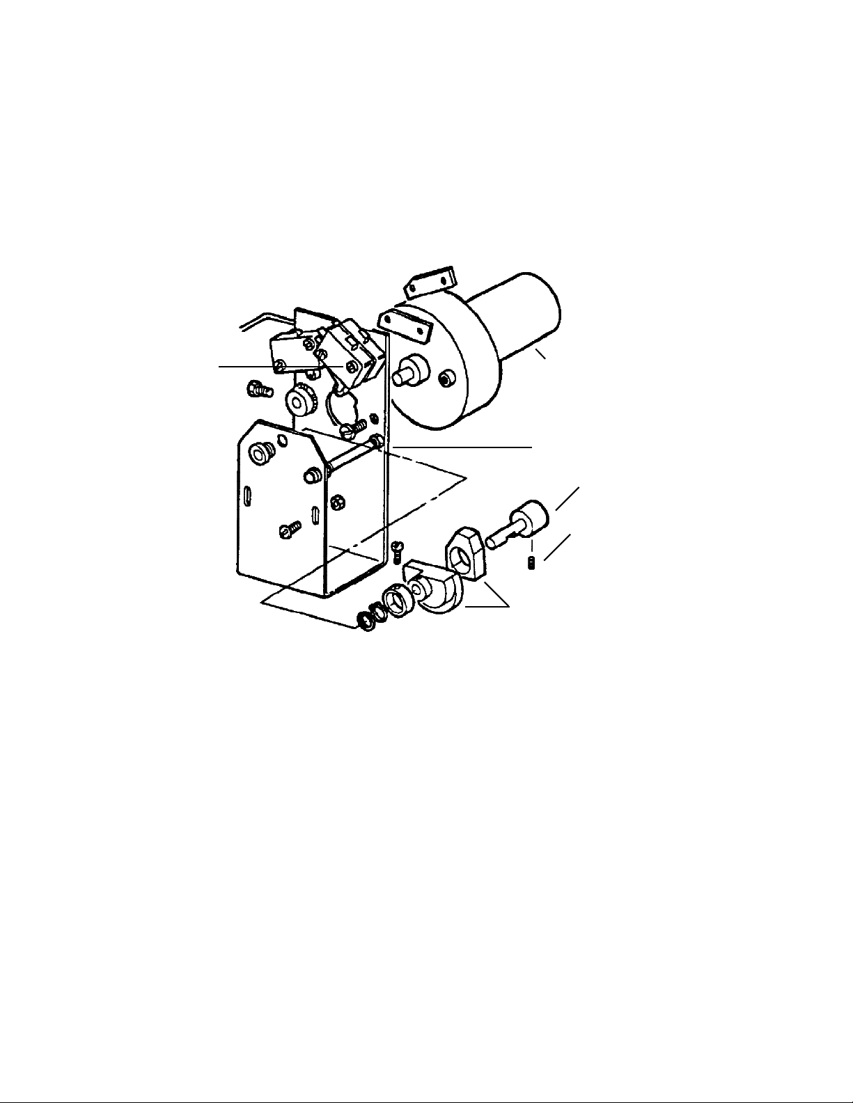
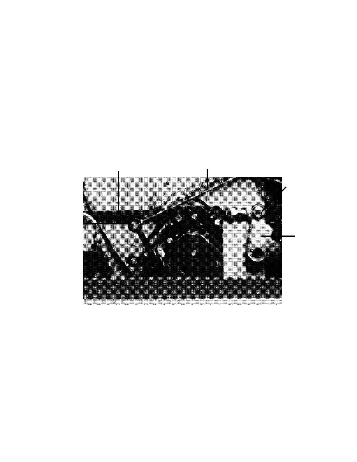
6.
Remove the SCREW (1 in FIGURE 2) that retains the two MICROSWITCHES, and then rotate
the MICROSWITCHES away from the CAM ASSEMBLY.
FIGURE 2
7.
SCREW 1
Remove the three SCREWS that secure the TILT MOTOR to the MOUNTING BRACKET.
Hold the CAM FOLLOWERS away from the CAMS and withdraw the TILT MOTOR. The
hole in the MOUNTING BRACKET is profiled to allow the withdrawal.
TILT MOTOR
MOUNTING BRACKET
SHAFT
GRUB SCREW
CAMS
8.
9.
10.
11.
MA 3211-31 August 1992
Change the existing SHAFT for the new SHAFT, reusing the GRUB SCREW. The new
SHAFT has the FLAT for the MICROSWITCH operating CAM advanced by 15 degrees
compared to the old SHAFT. This ensures the MICROSWITCHES are operated earlier.
Reassemble the TILT MOTOR on the MOUNTING BRACKET.
Replace the MICROSWITCH MOUNTING SCREW, and adjust the MICROSWITCHES so the
SWITCHES are not bottomed as the CAMS rotate.
Refit the TILT MOTOR ASSEMBLY in the MINILOADER and refit the LIGHT SEAL.
Refit the CASSETTE SUCKER BAR PUSH ROD onto the LEVER.
4
© Kodak Ltd.
Page 6

12.
Refit the TILT PUSH ROD.
13.
14.
Load some TEST FILM into the SUPPLY MAGAZINE and run some cycles to check the
operation of the TILT. If necessary adjust the speed of the TILT MOTOR by means of the
POTENTIOMETER P601 on PCB 106A/B. It should be possible to run the TILT MOTOR
faster now that the modification has been carried out.
Circle M31 on the MODIFICATION LABEL and refit the PANELS.
© Kodak Ltd. August 1992 MA 3211-31
5
Page 7

HEALTH SCIENCES DIVISION
MA 3211-31 August 1992
6
© Kodak Ltd.
Page 8

Publication Number. MA3234-M01
Issue number 1
MODIFICATION INSTRUCTIONS
for the
KODAK MINILOADER 1M,
MODELS STAND-ALONE, & PROCESSOR INTERFACE
Service Codes 3234, & 3235
MODIFICATION No. M01
Type 1 Required
PURPOSE:
To change the speed of the cam motor to stop cam system malfunctions, to prevent damage to the
cam motor relays, and lengthen the life of the cam motor. Film handling is also improved.
This modification will also prevent spurious blowing of the cam motor fuse.
IMPORTANT: Only qualified service personnel should install this modification!
SERIAL NUMBERS: 1500 - 1530
1700 - 1718
INSTALLATION TIME: Approximately 30 minutes.
SPECIAL TOOLS: None
PARTS REQUIREMENT: No parts required.
© Kodak Ltd. November 1992 MA 3234-1
1
Page 9

PARTS LIST
PART NO. DESCRIPTION QUANTITY
MA3234-M01 MODIFICATION INSTRUCTIONS 1
CAUTION
This equipment includes parts and assemblies sensitive to damage from electrostatic
discharge. Use caution to prevent damage during all service procedures.
PLEASE NOTE
The information contained herein is based on the experience and knowledge relating to the subject matter
gained by Kodak Limited prior to publication.
No patent license in granted by this information.
Kodak Limited reserves the right to change this information without notice, and makes no warranty,
express or implied, with respect to this information. Kodak shall not be liable for any loss or damage,
including consequential or special damages, resulting from the use of this information, even if the loss or
damage is caused by Kodak’s negligence or other fault.
MA 3234-1 November 1992
2
© Kodak Ltd.
Page 10
MODIFICATION INSTRUCTIONS
Switch off the power to the MINILOADER and remove the TOP COVER and the right hand (from the
1.
front) SIDE PANEL.
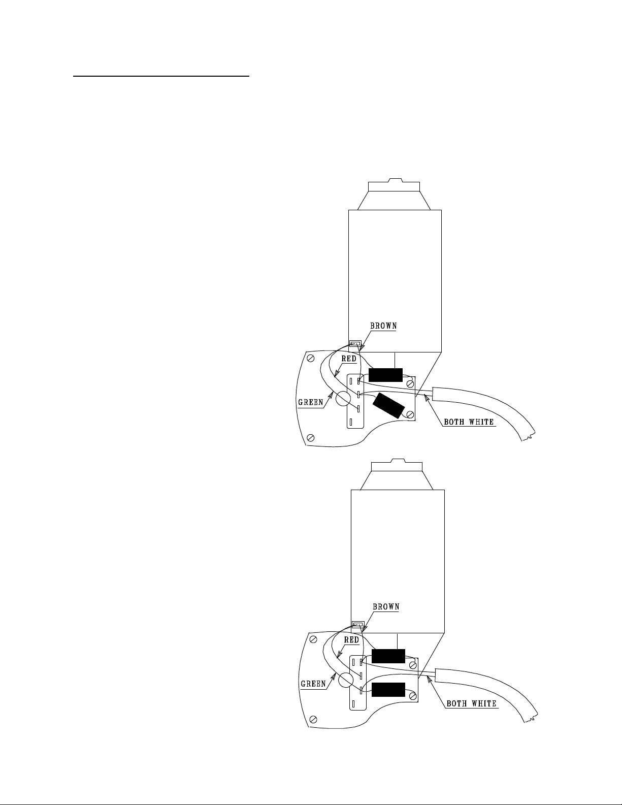
2.
On the CAM MOTOR, identify the CONNECTOR STRIP. Un-solder the WHITE WIRE marked "C"
and the CAPACITOR from the CONNECTION that the RED MOTOR WIRE is connected to, and resolder the WHITE WIRE and the CAPACITOR to the CONNECTION that the GREEN MOTOR
WIRE is connected to. See FIGURES 1 & 2.
FIGURE 1.
Before the modification.
FIGURE 2.
After the modification.
© Kodak Ltd. November 1992 MA 3234-1
3
Page 11

Replace the right hand SIDE PANEL, and turn the power to the MINILOADER on.
3.
Using the SWITCHES on PCB 303 enter the PROGRAMMING MODE. (SWITCH 1 ON) Check that
4.
the DATE & TIME are still correct, reset if necessary.
Check the SERIAL NUMBER is still correct, change if necessary.
Select the required LANGUAGE.
Note that PARAMETER P3, "MULTIPLE FILM DETECTION PAUSE" can now be reduced to 0.5
Seconds (previously 1.0 Second) because as the CAM MOTOR is now moving more slowly, less time
is required for the FILM to stabilise.
On most MINILOADERS, the cycle time after doing this modification does not change. This is
5.
because although the CAM MOTOR is running more slowly, the time for HOME POSITION to be
reached at the end of the cycle is much reduced as, due to the slower speed, the program is able to stop
the CAM MOTOR in HOME POSITION first time, and does not need to "hunt" for HOME
POSITION. However, on PROCESSOR INTERFACE MINILOADERS, it is necessary to check that
PARAMETER P4 "GAP BETWEEN FILMS" is still correctly set. The correct way to do this is to
check the gap between films leaving the PROCESSOR in SERIAL MODE, and alter PARAMETER
P4 if necessary.
Circle MOD M01 on the MODIFICATION LABEL, re-assemble the MINILOADER and test .
6.
HEALTH SCIENCES DIVISION
CUSTOMER EQUIPMENT SERVICES DIVISION, SWALLOWDALE LANE, HEMEL HEMPSTEAD, HERTFORDSHIRE, ENGLAND.
MA 3234-1 November 1992
4
© Kodak Ltd.
Page 12

Publication Number. MB3211-32
MODIFICATION INSTRUCTIONS
for the
KODAK MINILOADER 1
Service Codes 3211, 3212
MODIFICATION No. M32
Type 2
Issue number 1
PURPOSE:
On some MINILOADERS it is not possible to adjust the MAGAZINE SUCKER BAR to prevent FILMS
being pulled back out of the CASSETTE by the SUCKERS as the SUCKER BAR returns from the
CASSETTE.
This modification replaces the old SUCKER BAR with a bar of a new shape.
The new SUCKER BAR can be identified by a white spot on the mounting.
IMPORTANT: Only qualified service personnel should install this modification!
SERIAL NUMBERS: All
INSTALLATION TIME: Approximately 1 hour.
SPECIAL TOOLS: STEP BY STEP SWITCH Part no. 29035052
SPRING BALANCE 0 - 5 kg Part no. 29030707
PARTS REQUIREMENT: See Parts list.
© Kodak Ltd. June 1992 MB 3211-32
1
Page 13
PARTS LIST
PART NO. DESCRIPTION QUANTITY
30092032 MODIFICATION KIT 1
THE KIT CONTAINS:
30012380 MAGAZINE SUCKER BAR 1
MA3211-32 MODIFICATION INSTRUCTIONS 1
CA UTION
This equipment includes parts and assemblies sensitive to damage from electrostatic
discharge. Use caution to prevent damage during all service procedures.
PLEASE NOTE
The information contained herein is based on the experience and knowledge relating to the subject matter
gained by Kodak Limited prior to publication.
No patent license in granted by this information.
Kodak Limited reserves the right to change this information without notice, and makes no warranty,
express or implied, with respect to this information. Kodak shall not be liable for any loss or damage,
including consequential or special damages, resulting from the use of this information, even if the loss or
damage is caused by Kodak’s negligence or other fault.
MB 3211-32 June 1992
2
© Kodak Ltd.
Page 14
MODIFICATION INSTRUCTIONS
1. Remove the MINILOADER COVER and the non-drive SIDE PANEL. Remove the FILM
MAGAZINE(S). Unload the SUPPLY MAGAZINE and place some TEST FILMS in it. Replace the
SUPPLY MAGAZINE in the MINILOADER.
2. Remove the MAGAZINE SUCKER BAR from the MINILOADER, retain the SUCKERS and
discard the old BAR. IMPORTANT - Do not touch the surface of the SUCKER with your hand,
use a GLOVE or a CLEAN CLOTH to handle the SUCKERS.
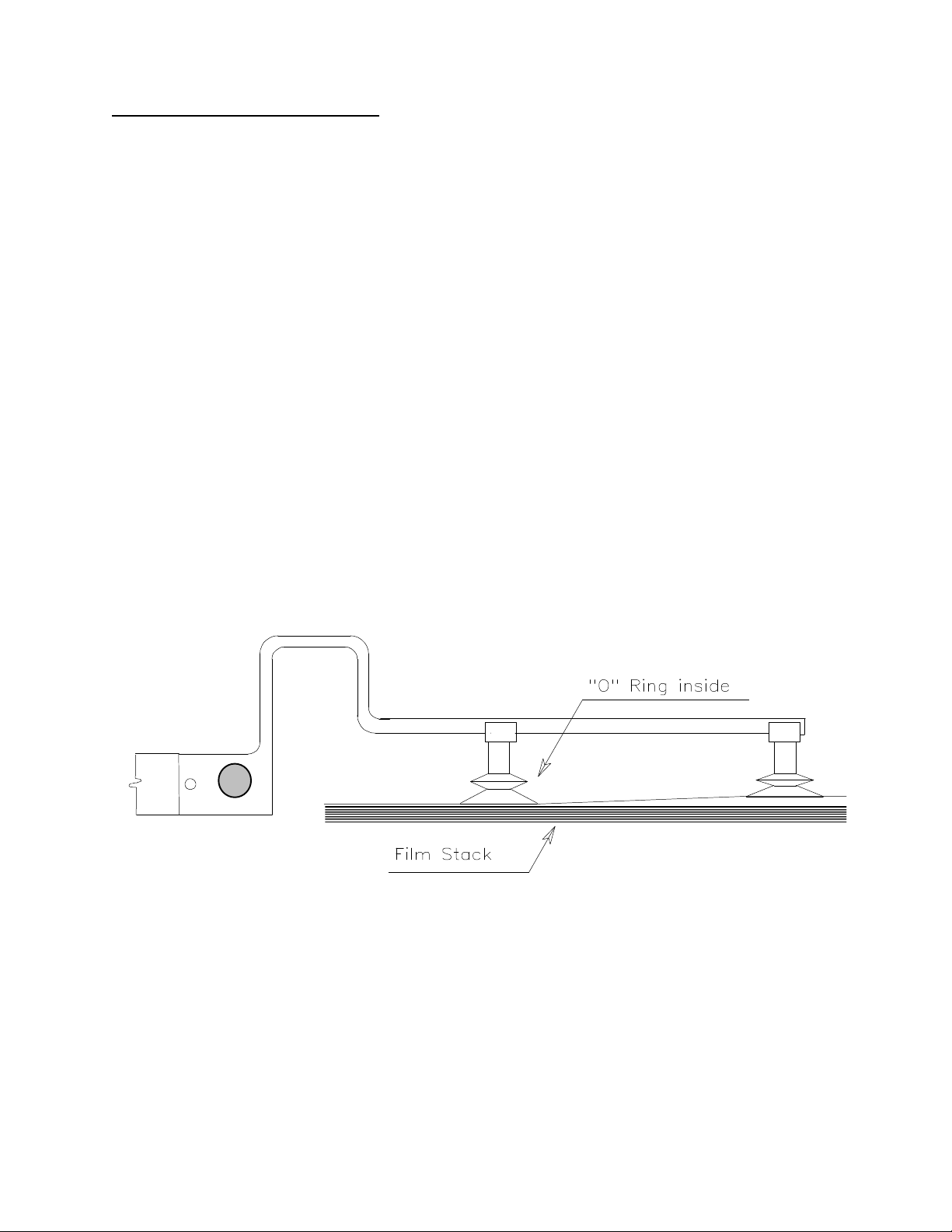
3. Fit the SUCKERS on the new SUCKER BAR IMPORTANT - Make sure the SUCKER with the
“O” RING inside is fitted to the mounting end of the SUCKER BAR.. This ensures correct
separation of FILMS when the vacuum is applied to the SUCKERS. See Figure 1.
F igure 1.
© Kodak Ltd. June 1992 MB 3211-32
3
Page 15
4. Fit the new SUCKER BAR to the MINILOADER taking care not to damage the "O" RING SEAL
inside the SUCKER BAR MOUNTING. Using the JOG SWITCH (on PCB 106) jog the machine
until the MAGAZINE SUCKER BAR is just above the TEST FILM in the SUPPLY MAGAZINE.
See Figure 2. Loosen the two GRUB SCREWS on the SUCKER BAR and adjust the angle of the
BAR, so the SUCKERS are parallel with the FILM. If necessary alter the individual SUCKERS, so
both SUCKERS are parallel..
5. Jog the machine further through the cycle and make sure that the SUCKER BAR does not touch the
CASSETTE SCREEN as the SUCKER BAR enters and leaves the CASSETTE.
F igure 2.
There must be clearance between the sucker
bar and the cassette screen here.
Suckers parallel
to the films
here
MB 3211-32 June 1992
There should be a gap of 1 mm between the sucker
and the film when the vacuum is released.
4
© Kodak Ltd.
Page 16

6. Fit the STEP BY STEP SWITCH to the MINILOADER (see the SERVICE MANUAL for
instructions if necessary). Run some cycles and check that the FILMS enter the CASSETTE
correctly.
The FILM should be “tucked into” the HINGE of the CASSETTE without catching the BASE of the
CASSETTE or the SCREEN. The FILM must not be pulled back out of the CASSETTE when the
SUCKER BAR returns. There should be a gap of a least one millimetre between the FILM and the
SUCKER when the vacuum is released.
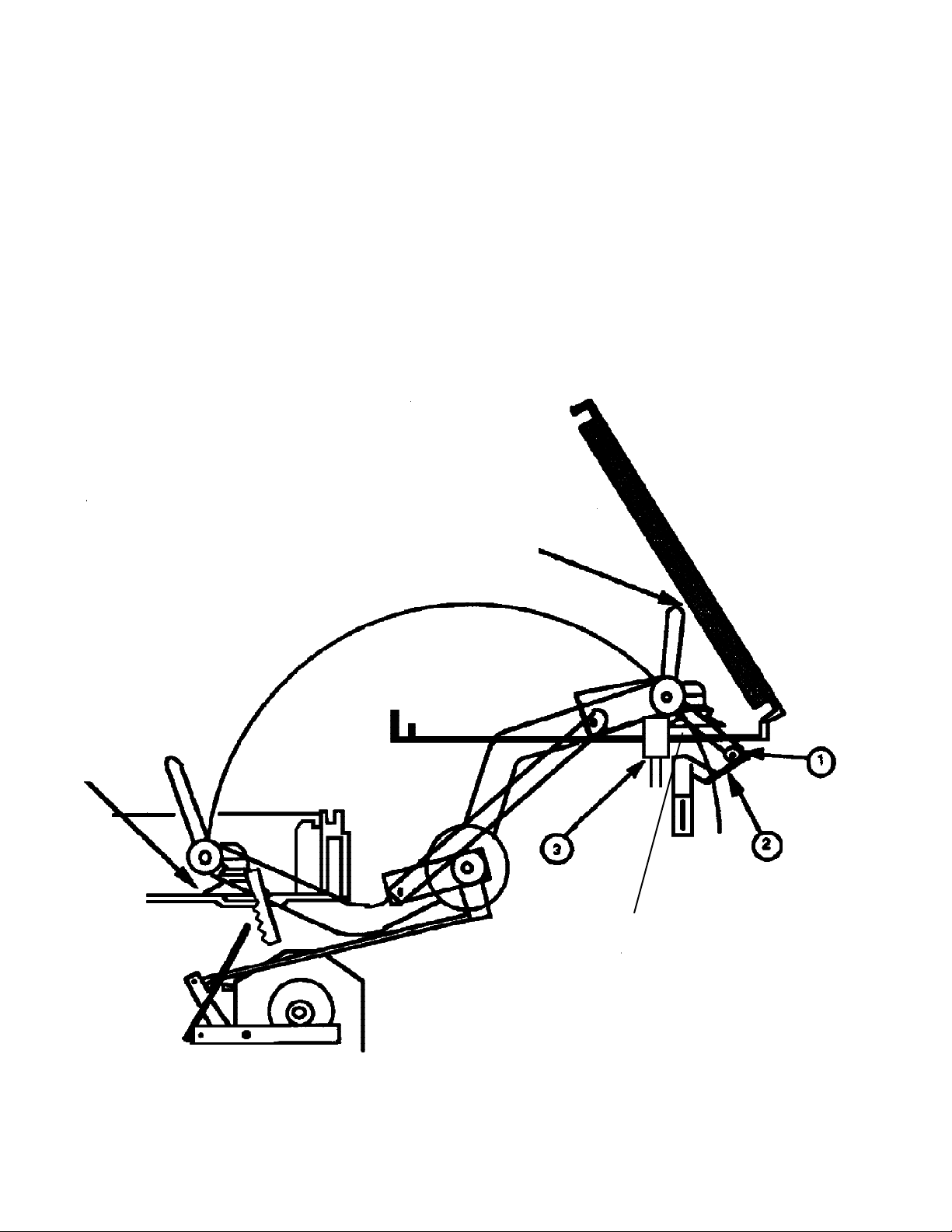
If necessary adjust the angle of the CAM FOLLOWER (1), the height and/or angle of the STATIC
CAM (2) or the height of the STOP (3). It may also be necessary to adjust one of the PUSH RODS
which drive the SUCKER BAR.
7. When the FILM is entering the CASSETTE correctly, check that the SUCKER BAR presses against
the STOP (3) with a force of 0.5 to 1 kg. Adjust the PUSHROD if required.
8. Circle M 32 on the MODIFICATION LABEL, replace the SIDE PANEL and the LID of the
MINILOADER. Reload the MAGAZINE(S) and if possible process some film to check for
ARTIFACTS.
© Kodak Ltd. June 1992 MB 3211-32
5
Page 17

HEALTH SCIENCES DIVISION
CUSTOMER EQUIPMENT SERVICES DIVISION, SWALLOWDALE LANE, HEMEL HEMPSTEAD, HERTFORDSHIRE, ENGLAND.
MB 3211-32 June 1992
6
© Kodak Ltd.
Page 18

Publication Number. MA3211-M33
MODIFICATION INSTRUCTIONS
for the
KODAK MINILOADER 1
Service Codes 3211, 3212
MODIFICATION No. M33
Type 1 SELECTIVE
Issue number 2
PURPOSE:
To replace PCB 101A or PCB 101B with a modified PCB 101C to prevent the CONVEYOR BELT
running in reverse at the end of a cycle. The new PCB has a SOLID STATE RELAY to replace
TIMER T6. This modification replaces Modification M28.
IMPORTANT - The new PCB 101C cannot replace PCB 101, only PCB 101A & PCB 101B.
IMPORTANT: Only qualified service personnel should install this modification!
SERIAL NUMBERS: 1162 - 1412
Plus 1101 - 1161 with a serial number suffix M.
INSTALLATION TIME: Approximately 1 hour.
SPECIAL TOOLS: Test film.
PARTS REQUIREMENT: See Parts list.
PARTS AVAILABILITY: End of September 1992.
© Kodak Ltd. November 1992 MA 3211-33
1
Page 19

PARTS LIST
PART NO. DESCRIPTION QUANTITY
30090033 MODIFICATION KIT 1
THE KIT CONTAINS:
30015981 PCB 101C 1
HTL 1217 STATIC SENSITIVE LABEL 1
MA3211-33 MODIFICATION INSTRUCTIONS 1
CA UTION
This equipment includes parts and assemblies sensitive to damage from electrostatic
discharge. Use caution to prevent damage during all service procedures.
PLEASE NOTE
The information contained herein is based on the experience and knowledge relating to the subject matter
gained by Kodak Limited prior to publication.
No patent license in granted by this information.
Kodak Limited reserves the right to change this information without notice, and makes no warranty,
express or implied, with respect to this information. Kodak shall not be liable for any loss or damage,
including consequential or special damages, resulting from the use of this information, even if the loss or
damage is caused by Kodak’s negligence or other fault.
MA 3211-33 November 1992
2
© Kodak Ltd.
Page 20

MODIFICATION INSTRUCTIONS
1.
2.
3.
4.
Switch off the MINILOADER and remove the SUPPLY MAGAZINE and the ELECTRICAL
COVER.
Remove PCB 101A or PCB 101B (whichever is fitted) and replace it with PCB 101C. Re-pack
the old PCB in the ANTI-STATIC BAG and re-seal the BAG with the STATIC SENSITIVE
LABEL supplied in the MODIFICATION KIT. Tick the "UNFIT FOR STOCK" box and write
the SERIAL NUMBER of the MINILOADER on the LABEL. The old PCB must be returned to
your SPARES SERVICES DEPARTMENT.
Load the SUPPLY MAGAZINE with TEST FILM. Run some cycles to check the operation of
the MINILOADER. Check the settings of the TIMERS on PCB 101C. IMPORTANT, if the
MINILOADER is a PROCESSOR INTERFACE MODEL, do not forget to set TIMER T14 to
suit the processing cycle being used.
Replace all parts and circle M 33 on the MODIFICATION LABEL.
5.
© Kodak Ltd. November 1992 MA 3211-33
Use the normal procedure in your country to send the old PCB back to your SPARES
SERVICES so it can be modified. If the old PCB is not returned, with the SERIAL NUMBER
of the MINILOADER which it was removed from written on it, your country will not receive
credit for it.
3
Page 21

HEALTH SCIENCES DIVISION
CUSTOMER EQUIPMENT SERVICES DIVISION, SWALLOWDALE LANE, HEMEL HEMPSTEAD, HERTFORDSHIRE, ENGLAND.
MA 3211-33 November 1992
4
© Kodak Ltd.
Page 22

Publication Number. MA3211-M34
Issue number 1
MODIFICATION INSTRUCTIONS
for the
KODAK MINILOADER 1
MODELS STAND-ALONE, & PROCESSOR INTERFACE
Service Codes 3211, & 3212
MODIFICATION No. M34
Type 1 Selective
PURPOSE:
To change the speed of the cam motor to stop cam system malfunctions, to prevent damage to the
cam motor relays, and lengthen the life of the cam motor. The cam motor is run at a slower speed, and the
cycle time is maintained by changing the gearing of the cam system.
IMPORTANT: Only qualified service personnel should install this modification!
SERIAL NUMBERS: All.
INSTALLATION TIME: Approximately 1 hour.
SPECIAL TOOLS: CAM CLUTCH TOOL M224 30015677
SPRING BALANCE 0 - 20Kg 29030715
PARTS REQUIREMENT: MODIFICATION KIT 30090034
See Parts List on page 2.
PARTS AVAILABILITY: November 1992.
© Kodak Ltd. November 1992 MA 3211-34
1
Page 23

PARTS LIST
PART NO. DESCRIPTION QUANTITY
30013391 CAM MOTOR SPROCKET 1
MA3211-M34 MODIFICATION INSTRUCTIONS 1
CAUTION
This equipment includes parts and assemblies sensitive to damage from electrostatic
discharge. Use caution to prevent damage during all service procedures.
PLEASE NOTE
The information contained herein is based on the experience and knowledge relating to the subject matter
gained by Kodak Limited prior to publication.
No patent license in granted by this information.
Kodak Limited reserves the right to change this information without notice, and makes no warranty,
express or implied, with respect to this information. Kodak shall not be liable for any loss or damage,
including consequential or special damages, resulting from the use of this information, even if the loss or
damage is caused by Kodak’s negligence or other fault.
MA 3211-34 November 1992
2
© Kodak Ltd.
Page 24

MODIFICATION INSTRUCTIONS
1.
Turn off the power to the MINILOADER and remove the MAGAZINE(S).
2.
Remove the TOP COVER, the right hand (from the front) SIDE PANEL and the REAR PANEL. If
the MINILOADER is a STAND-ALONE machine, go to step 3. If the MINILOADER is connected
to a PROCESSOR, it will be necessary to disconnect the MINILOADER from the PROCESSOR. It
will also be necessary to dismount PHOTOCELL FC7 from the REAR PANEL as the PANEL is
removed.
On the CAM MOTOR, identify the CONNECTOR STRIP. Un-solder the WHITE WIRE marked "C"
3.
from the CONNECTION that the RED MOTOR WIRE is connected to, and re-solder the WHITE
WIRE to the CONNECTION that the GREEN MOTOR WIRE is connected to. See FIGURES 1 & 2.
FIGURE 1.
Before the modification.
FIGURE 2.
After the modification.
© Kodak Ltd. November 1992 MA 3211-34
3
Page 25

Peel back the two LIGHT SEAL STRIPS that cover the heads of the four MOTOR MOUNTING
4.
BRACKET SCREWS. Loosen the SCREWS so the MOTOR can be lowered. Lift the CHAIN off the
MOTOR SPROCKET. It should not be nesessary to split the CHAIN.
Loosen the GRUB SCREW on the MOTOR CLUTCH ADJUSTING NUT, and remove the NUT. See
5.
FIGURE 3. Remove the existing CAM MOTOR SPROCKET. CAUTION - TAKE CARE NOT TO
LOOSE THE THREE BALL BEARINGS FROM THE CLUTCH.
FIGURE 3
Three ball bearings
Two thrust washers
Motor hub
6.
Fit the NEW MOTOR SPROCKET, taking care that the BALL BEARINGS are correctly positioned.
Refit the MOTOR CLUTCH ADJUSTING NUT, and tighten by hand. Refit the CHAIN on the
SPROCKET (if nessesary the CHAIN can be split at the CONNECTING LINK) and move the
MOTOR MOUNTING BRACKET up to tension the CHAIN. Tighten the four fixing SCREWS and
replace the LIGHT SEAL STRIP. The CHAIN tension is correct when there is a free play of 4 mm at
the centre.
Nylon thrust washer
Tension adjustment nut
Locking grub screw
Sprocket assy.
MA 3211-34 November 1992
4
© Kodak Ltd.
Page 26

FIGURE 4
Using tool M224 (PART NUMBER
7.
30015677) reset the CAM SYSTEM to
HOME POSITION (MICROSWITCH MS1
made). Replace the MAGAZINE(S) making
sure that there is no CUSTOMER FILMS in
them. Set the tension of the CAM MOTOR
CLUTCH by using tool M224. See FIGURE
4. The CLUTCH should slip when a pull of
1.5 to 2 Kg is applied (2.0 to 2.5 Kg for a
STAND-ALONE machine). When the correct
tension is set, re-tighten the GRUB SCREW
in the ADJUSTING NUT.
Refit the REAR PANEL, remembering to refit PHOTOCELL FC7 on PROCESSOR INTERFACE
8.
MINILOADERS. Remount the MINILOADER on the PROCESSOR if appropriate.
Load the SUPPLY MAGAZINE with some TEST FILMS, and run some cycles to check that the
9.
CLUTCH does not slip. If necessary, re-adjust the CLUTCH TENSION.
Check the gap between films has not changed. If necessary adjust TIMER T14 on PCB 101B/101C
10.
(TIMER T3 on PCB 102 on MINILOADERS serial 1101 - 1161 without serial number suffix M).
Circle MODIFICATION M34 on the MODIFICATION LABEL and re-assemble the MINILOADER.
11.
© Kodak Ltd. November 1992 MA 3211-34
5
Page 27

HEALTH SCIENCES DIVISION
CUSTOMER EQUIPMENT SERVICES DIVISION, SWALLOWDALE LANE, HEMEL HEMPSTEAD, HERTFORDSHIRE, ENGLAND.
MA 3211-34 November 1992
6
© Kodak Ltd.
Page 28

Publication Number. MB3211-M35
MODIFICATION INSTRUCTIONS
for the
KODAK MINILOADER 1,
MODELS ST AND-ALONE, and PROCESSOR INTERF ACE
Service Codes 3211, & 3212
MODIFICATION No. M35
and for the
KODAK MINILOADER 1M
MODELS ST AND-ALONE, and PROCESSOR INTERF ACE
Service Codes 3234 & 3235
Issue number 1
MODIFICATION No. M04
Type 2
PURPOSE:
To install a HUMIDIFIER to maintain the humidity inside the MINILOADER. This will reduce problems associated
with FILM curl and static artifacts which may occur at low humidity.
IMPORTANT: Only qualified service personnel should install this modification!
SERIAL NUMBERS: Miniloader 1 Stand-Alone (3211) ALL
Miniloader 1 Processor-Interface (3212) ALL
Miniloader 1M Stand-Alone (3234) ALL
Miniloader 1M Processor-Interface (3235) ALL
INSTALLATION TIME: Approximately 1 hour.
SPECIAL TOOLS: HUMIDITY METER 29050132
PARTS REQUIREMENT: Modification kit 30092035
See parts lists on page 2.
PARTS AVAILABILITY: February 1994
© Kodak Ltd. February 1994 MB 3211-35
1
Page 29

PARTS LISTS
P ART NO. DESCRIPTION QUANTITY
30092035 MODIFICATION KIT 1
THE KIT CONTAINS:
30027102 HUMIDIFIER ASSY MINILOADER 1 & 1M 1
30027133 CABLE, HUMIDIFIER SUPPLY 1
CAUTION
This equipment includes parts and assemblies sensitive to damage from electrostatic discharge. Use
caution to prevent damage during all service procedures.
PLEASE NOTE
The information contained herein is based on the experience and knowledge relating to the subject matter
gained by Kodak Limited prior to publication.
No patent license in granted by this information.
Kodak Limited reserves the right to change this information without notice, and makes no warranty,
express or implied, with respect to this information. Kodak shall not be liable for any loss or damage,
including consequential or special damages, resulting from the use of this information, even if the loss or
damage is caused by Kodak’s negligence or other fault.
MB 3211-35 February 1994
2
© Kodak Ltd.
Page 30

INTRODUCTION.
The MODIFICATION replaces the existing right HAND SIDE PANEL of the MINILOADER with a new SIDE PANEL
containing a HUMIDIFIER. The new SIDE PANEL is 55 mm thicker than the original. The drawings below show the
outlines of the machines with the HUMIDIFIER fitted and the position of the plumbing connections. The position of the
WATER INLET and the DRAIN vary according to the model and configuration.
WATER SUPPLY
The incoming water supply specification is:Pressure range 0.3 to 5 Bar
Temperature 4 to 29oC
Volume approx. 1 litre/day
NOTE:- A 50 micron water filter should be provided by the customer.
STAND-ALONE
WATER
INLET
DRAIN
65mm
WATER
INLET
DRAIN
WITH M35 AND VERTAC
WATER
INLET
WATER
INLET
DRAIN
DRAIN
65mm
WITH M6/M6B/460RA/480RA
WATER
INLET
DRAIN
WATER
INLET
DRAIN
65mm
WITH M35 BACK TO BACK
WATER
INLET
DRAIN
WATER
INLET
DRAIN
© Kodak Ltd. February 1994 MB 3211-35
3
Page 31

MODIFICATION INSTRUCTIONS
Check that all the parts are present in the
1.
MODIFICATION KIT.
Remove the SUPPLY MAGAZINES, and turn
2.
off the power to the MINILOADER.
Remove the TOP COVER, FRONT PANEL,
3.
REAR PANEL and right hand SIDE PANEL.
Peel back the FOAM STRIP and remove the FAN
4.
SUPPORT and the FAN, see FIGURE 1.
Cut the wires to the FAN and discard the
5.
ASSEMBLY. Insulate the ends of the WIRES.
For MINILOADER 1M go to STEP 8.
6.
FIGURE 1
For MINILOADER 1, remove FUSE F4 from
7.
PCB 106/106A/106B and discard.
See FIGURE 2. Go to STEP 11.
FIGURE 2
FAN FUSE F4
PCB106/106A/106B
MB 3211-35 February 1994
4
© Kodak Ltd.
Page 32

For MINILOADER 1M, disconnect
8.
the FAN SUPPLY WIRE B4 from
PLUG X107-6 on PCB 301, see
FIGURE 3. Insulate the end of the
WIRE.
Disconnect the FAN SUPPLY WIRE
9.
N4 from TB1-17 on the MAIN TERMINAL BLOCK (inside the ELECTRICAL BOX). Insulate the end of the
WIRE.
Remove FUSE F4 from PCB 301. See
10.
FIGURE 3.
FIGURE 3
FUSE F4
PLUG X107
Connect the new CABLE 30027133 to
11.
the TRANSFORMER.
For MINILOADER 1 use the 11.5 volt
TAPPING of TRANSFORMER T1.
For the MINILOADER 1M use the
10 volt AC terminals of TRANSFORMER T2 - TB3-1 and TB3-2.
Feed the CABLE under the SIDE
PLATE. See FIGURE 4.
Plug the CABLE into the PLUG X1 on
12.
the HUMIDIFIER PCB, and fit the
HUMIDIFIER to the MINILOADER.
FIGURE 4
PLUG X1
CABLE 30027133
11.5 VOLT AC (MINILOADER 1)
10 VOLT AC (MINILOADER 1M)
© Kodak Ltd. February 1994 MB 3211-35
5
Page 33

Connect the WATER SUPPLY using a WASHING MACHINE HOSE and the DRAIN (a HOSE CONNECTOR
12.
is supplied) to the HUMIDIFIER. Note - if using a BOTTLE to supply water to the HUMIDIFIER the
RESTRICTOR 30027126 must be removed See FIGURE 5.
FIGURE 5
FILTER ELEMENT 30027202
AIR FILTER
HUMIDITY SENSOR
WET FAN
DRY FAN
DISPLAY
ADJUST
CALIBRATION
WATER INLET
3/4" BSP
DO NOT TOUCH
RESTRICTOR
30027126
WATER DRAIN 3/4" BSP
13.
If necessary install the HUMIDIFIER FILTER.
Go to PAGE 8.
SAFETY OVERFLOW
WATER RESERVOIR
WATER INLET
VALVE
MB 3211-35 February 1994
6
© Kodak Ltd.
Page 34

THIS PAGE IS INTENTIONALLY LEFT BLANK
© Kodak Ltd. February 1994 MB 3211-35
7
Page 35

Remove the clear plastic COVER and set the SELECTOR SWITCHES to the desired humidity. The recommended
14.
preset is 45%RH. Replace the COVER. See FIGURE 6.
FIGURE 6
DISPLAY
15.
16.
SELECTOR SWITCHES
Replace all the covers and power up the MINILOADER. The HUMIDIFIER should switch on automatically. If
the humidity inside the MINILOADER is greater than the preset value, only the DRY FAN will run. If the humidity
is below the preset value, the INLET WATER VALVE opens, the DRY FAN stops and the WET FAN starts to
increase the humidity inside the MINILOADER.
IMPORTANT :- If the humidity inside the MINILOADER is different (either higher or lower) from the preset value
after 10 minutes, the figures on the DISPLAY will flash. If the humidity is higher than the preset nothing can be
done, but if the humidity is lower, check the water supply, FLOAT VALVE and the FILTER ELEMENT.
The calibration of the HUMIDITY SENSOR is factory set, but if a HUMIDITY METER (29050132) is available
the calibration of the DISPLAY can be adjusted. After the unit has stabilised (after 30 minutes), measure the
humidity inside the MINILOADER by inserting the PROBE of the HUMIDITY METER through the ENTRY
SLOT. Compare the reading on the HUMIDITY METER with the HUMIDIFIER DISPLAY. If necessary the
HUMIDIFIER DISPLAY reading can be adjusted by POTENTIOMETER R11 on the HUMIDIFIER PCB 209.
See FIGURE 7.
COVER
IMPORTANT - DO NOT TOUCH THE VARIABLE CAPACITOR ON YOU WILL UPSET THE
FACTORY SETTING.
The SERVICE DETAILS for the HUMIDIFIER including the PARTS LIST will shortly be released as
PUBLICATION XP3291-1.
MB 3211-35 February 1994
8
© Kodak Ltd.
Page 36

FIGURE 7
HUMIDITY SENSOR
CALIBRATION - DO NOT TOUCH - FACTORY SET
PCB 209
DISPLAY ADJUSTMENT
Circle the appropriate MODIFICATION on the MODIFICATION STICKER inside the MINILOADER.
17.
MODIFICATION M35 for MINILOADER 1. MODIFICATION M04 for MINILOADER 1M.
FOR MINILOADER 1
FOR MINILOADER 1M
© Kodak Ltd. February 1994 MB 3211-35
9
Page 37

HEALTH SCIENCES DIVISION
CUSTOMER EQUIPMENT SERVICES DIVISION, SWALLOWDALE LANE, HEMEL HEMPSTEAD, HERTFORDSHIRE, ENGLAND.
Page 38

Publication Number. MB3211-M36
Issue number 1
MODIFICATION INSTRUCTIONS
for the
KODAK MINILOADER 1,
MODELS STAND-ALONE & PROCESSOR INTERFACE
Service Codes 3211 & 3212
MODIFICATION No. M36
Type 2
PURPOSE:
To fit a new SWF Cam Motor in order to improve the reliability of the MINILOADER.
IMPORTANT: Only qualified service personnel should install this modification!
SERIAL NUMBERS: Model Stand-Alone (3211) All
Model Processor Interface (3212) All
INSTALLATION TIME: Approximately 1 hour.
SPECIAL TOOLS: None
PARTS REQUIREMENT: Modification kit 30092036
See parts list on page 2.
PARTS AVAILABILITY: December 1994
© Kodak Ltd. November 1994 MB 3211-36
1
Page 39

PARTS LIST
P ART NO. DESCRIPTION QUANTITY
30092036 MODIFICATION KIT 1
THE KIT CONTAINS:
30025250 SWF CAM MOTOR (FITTED WITH
SMALL SPROCKET 30026362) 1
30015697 FASTON CONNECTORS 2
30014391 LARGE MOTOR SPROCKET ASSY. 1
MB3211-M36 MODIFICATION INSTRUCTIONS 1
CAUTION
This equipment includes parts and assemblies sensitive to damage from electrostatic discharge. Use
caution to prevent damage during all service procedures.
PLEASE NOTE
The information contained herein is based on the experience and knowledge relating to the subject matter
gained by Kodak Limited prior to publication.
No patent license in granted by this information.
Kodak Limited reserves the right to change this information without notice, and makes no warranty,
express or implied, with respect to this information. Kodak shall not be liable for any loss or damage,
including consequential or special damages, resulting from the use of this information, even if the loss or
damage is caused by Kodak’s negligence or other fault.
MB 3211-36 November 1994
2
© Kodak Ltd.
Page 40

MODIFICATION INSTRUCTIONS
Turn off the power to the MINILOADER.
1.
Remove the TOP COVER and the right hand (from
2.
the front) SIDE PANEL.
Cut the WIRES from the existing CAM
3.
MOTOR, and remove the MOTOR from the
MINILOADER.
If necessary, fit the SPROCKET that is the
4.
same size as the one fitted to the original
MOTOR to the new MOTOR.
Using the original SCREWS mount the new
5.
CAM MOTOR. See FIGURE.
Fit the FASTON CONNECTORS to the
6.
MOTOR LEADS and connect to the MOTOR
TERMINALS.
NEW CAM
MOTOR
Ensure the MOTOR turns in the correct
7.
direction, if necessary reverse the MOTOR
LEADS.
Set the MOTOR CLUTCH to the correct
8.
tension as detailed in the SERVICE MANUAL.
Using TEST FILM check the operation of the
9.
MINILOADER.
If the MINILOADER is PROCESSOR
10.
INTERFACED, check TIMER T14, "FEED
DELAY" (TIMER T3 for serial numbers below
1162) is set correctly as there will be a slight
cycle time difference with the new MOTOR.
Circle M36 on the MODIFICATION LABEL
11.
and replace the PANELS.
EXISTING
SUPPORT
© Kodak Ltd. November 1994 MB 3211-36
3
Page 41

HEALTH SCIENCES DIVISION
CUSTOMER EQUIPMENT SERVICES DIVISION, SWALLOWDALE LANE, HEMEL HEMPSTEAD, HERTFORDSHIRE, ENGLAND.
Page 42

Publication Number. MB3234-M03
Issue number 1
MODIFICATION INSTRUCTIONS
for the
KODAK MINILOADER 1M,
MODELS STAND-ALONE & PROCESSOR INTERFACE
Service Codes 3234 & 3235
MODIFICATION No. M03
Type 2
PURPOSE:
To replace three glass FUSES with auto-resetting devices. This will eliminate service calls that are made purely to
replace blown fuses.
IMPORTANT: Only qualified service personnel should install this modification!
SERIAL NUMBERS: 1500 - 1537
1700 - 1718
INSTALLATION TIME: Approximately 30 minutes.
SPECIAL TOOLS: None
PARTS REQUIREMENT: Modification kit 30092103
See parts list on page 2.
PARTS AVAILABILITY: August 1993
© Kodak Ltd. July 1993 MB 3234-3
1
Page 43

PARTS LIST
P ART NO. DESCRIPTION QUANTITY
30092103 MODIFICATION KIT 1
THE KIT CONTAINS:
30025886 MULTIFUSE R250 2
30025888 MULTIFUSE R050 1
MB3234-M03 MODIFICATION INSTRUCTIONS 1
CAUTION
MB 3234-3 July 1993
2
© Kodak Ltd.
Page 44

INFORMATION ABOUT THE MULTIFUSES.
BOURNS MULTIFUSE protectors act like a FUSE under over-current conditions. Unlike a FUSE they are resettable.
A MULTIFUSE is a solid state device with a positive temperature coefficient. The MULTIFUSE is used in series with
the power source and the circuit or component that have to be protected against damage or fire.
Under normal operating conditions the resistance of the MULTIFUSE is comparable to that of a fuse link, between
milliohms and a few ohms, depending on the specified current carrying capacity.
The MULTIFUSE undergoes an abrupt change in resistance when an over-current heats it up to its "trip" temperature,
about 125oC. This increase limits the current from the power source and the circuit to be protected to a value which normally
does not cause any harm. Switch-off times are similar to those of slow-blow fuse-links. The remaining current keeps the
MULTIFUSE above its trip temperature and latches it in the protective high resistance state.
The MULTIFUSE will reset, which means it will return to its low resistance state, if it is allowed to cool to below its trip
temperature. This can be achieved if power is switched off ,or if the current is substantially reduced. Once the
MULTIFUSE is reset, and the fault condition has been cleared, the normal circuit operation resumes.
A MULTIFUSE always fails safe, which means that it will go towards high resistance.
The TABLE below shows the normal resistance at room temperature of each of the three devices used, the normal holding
current (MULTIFUSE will not trip) and the typical trip current. The actual trip current will depend on ambient conditions.
The typical reset time is less than 20 seconds at 20oC, and the expected life is about 200 reset cycles.
CAUTION :- The maximum surface temperature in the tripped state is 125oC.
DEVICE HOLDING CURRENT
RESISTANCE AT ROOM
TEMPERATURE
TRIP CURRENT
R050 500 m Amp 0.5 - 1.2 OMH 750 m AMP
R250 2.5 AMP 0.02 - 0.08 OHM 4.25 AMP
These devices would
normally be soldered onto the
PCB, but to facilitate the
fitting to existing PCB's, they
are supplied mounted on a
FUSE CARRIER.
NEW FUSE CARRIER WITH
MULTIFUSE FITTED
EXISTING FUSE HOLDER
( SOLDERED TO PCB )
© Kodak Ltd. July 1993 MB 3234-3
3
Page 45

MODIFICATION INSTRUCTIONS
Turn off the power to the MINILOADER.
1.
Remove the TOP COVER and the FRONT PANEL. Make sure you disconnect all CABLES as you remove
2.
the FRONT PANEL.
Pull the PCB 301 forwards and remove the SCREWS which hold the clear plastic PROTECTION COVER in
3.
place. Disconnect the POTENTIOMETER for the TILT MOTOR ( PLUG X111) and remove the COVER.
Taking ESD precautions, remove the FUSE CARRIERS for FUSES F7, F6, and F5. See FIGURE 1.
4.
FIGURE 1
*
*
*
REMOVE THESE
*
FUSE CARRIERS
TILT MOTOR PLUG
MB 3234-3 July 1993
4
© Kodak Ltd.
Page 46

5.
Using the TABLE below, fit the new MULTIFUSES into the existing FUSEHOLDERS.
FUSE POSITION PURPOSE MULTIFUSE PART NUMBER
F7 CAM MOTOR R250 30025886
F6 CASSETTE CONVEYOR MOTOR R250 30025886
F5 TILT MOTOR R050 30025888
6.
Plug the TILT MOTOR POTENTIOMETER back into PLUG X111, and refit the PROTECTION COVER
on PCB 301.
7.
Push the PCB 301 ASSY back into position, and refit the FRONT PANEL. Make sure all the PLUGS are
refitted as you replace the PANEL.
8.
Circle M03 on the MODIFICATION LABEL.
9.
Refit the TOP COVER and test the MINILOADER. Make sure you test all sizes.
10.
Inform the operator that in the event of an ERROR CODE being displayed that cannot be cleared by the
RESET BUTTON, to switch the MINILOADER off for 1 minute and they try again to reset the machine.
© Kodak Ltd. July 1993 MB 3234-3
5
Page 47

HEALTH SCIENCES DIVISION
CUSTOMER EQUIPMENT SERVICES DIVISION, SWALLOWDALE LANE, HEMEL HEMPSTEAD, HERTFORDSHIRE, ENGLAND.
Page 48

Publication Number. MB3234-M05
Issue number 1
MODIFICATION INSTRUCTIONS
for the
KODAK MINILOADER 1M,
MODELS STAND-ALONE & PROCESSOR INTERFACE
Service Codes 3234 & 3235
MODIFICATION No. M05
Type 2
PURPOSE:
To fit a new SWF Cam Motor and a PCB to replace the Cam motor Relays in order to improve the reliability of the
MINILOADER.
IMPORTANT: Only qualified service personnel should install this modification!
SERIAL NUMBERS: Model Stand-Alone (3234) All
Model Processor Interface (3235) All
INSTALLATION TIME: Approximately 1 hour.
SPECIAL TOOLS: None
PARTS REQUIREMENT: Modification kit 30092105
See parts list on page 2.
PARTS AVAILABILITY: December 1994
© Kodak Ltd. November 1994 MB 3234-5
1
Page 49

PARTS LIST
P ART NO. DESCRIPTION QUANTITY
30092105 MODIFICATION KIT 1
THE KIT CONTAINS:
30025250 SWF CAM MOTOR (FITTED WITH
SMALL SPROCKET 30026362) 1
30015697 FASTON CONNECTORS 2
30014391 LARGE MOTOR SPROCKET ASSY. 1
30014392 PCB100 1
MB3234-M05 MODIFICATION INSTRUCTIONS 1
CAUTION
This equipment includes parts and assemblies sensitive to damage from electrostatic discharge. Use
caution to prevent damage during all service procedures.
PLEASE NOTE
The information contained herein is based on the experience and knowledge relating to the subject matter
gained by Kodak Limited prior to publication.
No patent license in granted by this information.
Kodak Limited reserves the right to change this information without notice, and makes no warranty,
express or implied, with respect to this information. Kodak shall not be liable for any loss or damage,
including consequential or special damages, resulting from the use of this information, even if the loss or
damage is caused by Kodak’s negligence or other fault.
MB 3234-5 November 1994
2
© Kodak Ltd.
Page 50

MODIFICATION INSTRUCTIONS
Turn off the power to the MINILOADER.
1.
Remove the TOP COVER, the right hand (from the front) SIDE PANEL and the FRONT PANEL. Ensure all leads
2.
are disconnected when removing the FRONT PANEL.
Pull the PCB 301 forwards and remove the SCREWS which hold the clear plastic PROTECTION COVER in
3.
place. Disconnect the POTENTIOMETER for the TILT MOTOR (PLUG X111) and remove the COVER.
Taking ESD precautions, identify and remove the following RELAYS see the FIGURE on below :-
4.
K7-F CAM MOTOR FORWARD
K7-R CAM MOTOR REVERSE
Plug the new PCB 100 into the vacated RELAY SOCKETS (it will only fit one way round) making sure that the
5.
PINS on the PCB are fully inserted into the SOCKETS.
Plug the TILT MOTOR POTENTIOMETER back into SOCKET X111, and refit the plastic PROTECTION
6.
COVER to PCB 301.
Push PCB 301 back into position, and refit the FRONT PANEL making sure all the PLUGS are re-connected. Do
7.
not forget to reconnect the GROUND LEAD or MICROPROCESSOR malfunctions can result.
REMOVE THESE
RELAYS AND
REPLACE WITH
THE PCB 100.
TILT MOTOR PLUG
© Kodak Ltd. November 1994 MB 3234-5
3
Page 51

Cut the WIRES from the existing CAM MOTOR, and remove the MOTOR from the MINILOADER.
8.
If necessary, fit the SPROCKET that is the same size as the one fitted to the original MOTOR to the new
9.
MOTOR.
See the FIGURE below. Cut or bend the corner of the KEYPAD SUPPORT to allow clearance for the new
10.
MOTOR.
Using the original SCREWS mount the new CAM MOTOR.
11.
Fit the FASTON CONNECTORS to the MOTOR LEADS and connect to the MOTOR TERMINALS.
12.
Ensure the MOTOR turns in the correct direction, if necessary reverse the MOTOR LEADS.
13.
Set the MOTOR CLUTCH to the correct tension as detailed in the SERVICE MANUAL.
14.
KEYPAD SUPPORT
CUT OR BEND KEYPAD
SUPPORT
NEW CAM
MOTOR
EXISTING
SUPPORT
MB 3234-5 November 1994
4
© Kodak Ltd.
Page 52

Using TEST FILM check the operation of the MINILOADER.
15.
If the MINILOADER is PROCESSOR INTERFACED, check the PARAMETER, "GAP BETWEEN
16.
FILMS" is set correctly as there will be a slight cycle time difference with the new MOTOR.
Circle M05 on the MODIFICATION LABEL and replace the PANELS.
17.
© Kodak Ltd. November 1994 MB 3234-5
5
Page 53

HEALTH SCIENCES DIVISION
CUSTOMER EQUIPMENT SERVICES DIVISION, SWALLOWDALE LANE, HEMEL HEMPSTEAD, HERTFORDSHIRE, ENGLAND.
 Loading...