

Page 1
Publication No. XP 3239-2
Issue 2
March 1995
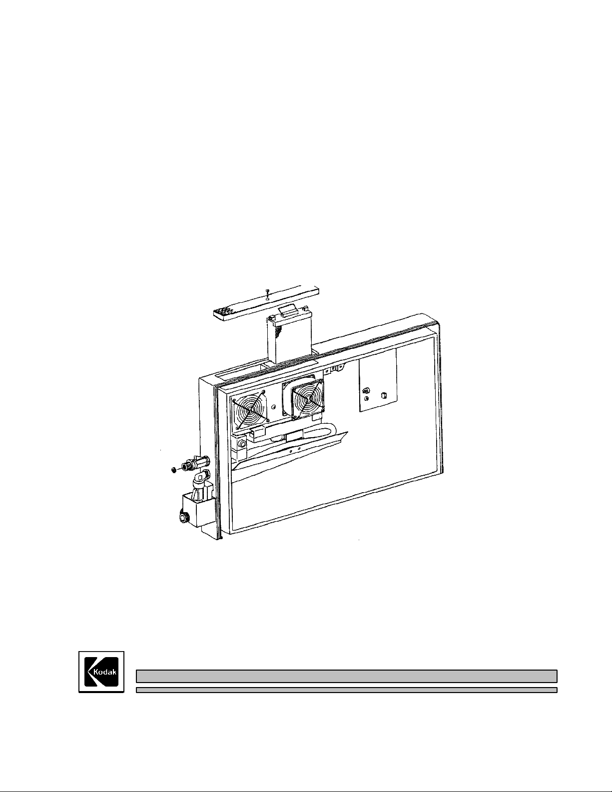
HUMIDIFIER SERVICE MANUAL
for all
Kodak MINILOADER'S
M8_FIG10.TIF
Use this Publication for:All Miniloaders fitted with the Humidifier Kit, and Low Voltage Miniloaders Service Codes 3419, 3420 & 3421
HEALTH SCIENCES DIVISION
© Kodak Ltd. 1995
Page 2

XP 3239-2 HUMIDIFIER ASSEMBLY
CAUTION
This equipment includes parts and assemblies sensitive to damage from electrostatic
discharge. Use caution to prevent damage during all service procedures.
© Kodak Ltd.
PLEASE NOTE
The information contained herein is based on the experience and knowledge
relating to the subject matter gained by Kodak Ltd. prior to publication.
No patent licence is granted by this information.
Kodak reserves the right to change this information without notice, and makes no warranty,
express or implied, with respect to this information. Kodak shall not be liable for any loss or
damage, including consequential or special damages, resulting from the use of this information,
even if loss or damage is caused by Kodak's negligence or other fault.
Page XP/2-2
March 1995
Page 3

HUMIDIFIER ASSEMBLY
THEORY GUIDE 4
INSTALLATION INSTRUCTIONS 6
SERVICE 7
XP 3239-2
CONTENTS
PAGE
PCB 208 CIRCUIT 10
PCB 209 CIRCUIT 12
PCB 208 OVERLAY 13
PCB 209 OVERLAY 14
PARTS LIST 15
March 1995
Page XP/2-3
© Kodak Ltd.
Page 4

XP 3239-2 HUMIDIFIER ASSEMBLY
THEORY GUIDE.
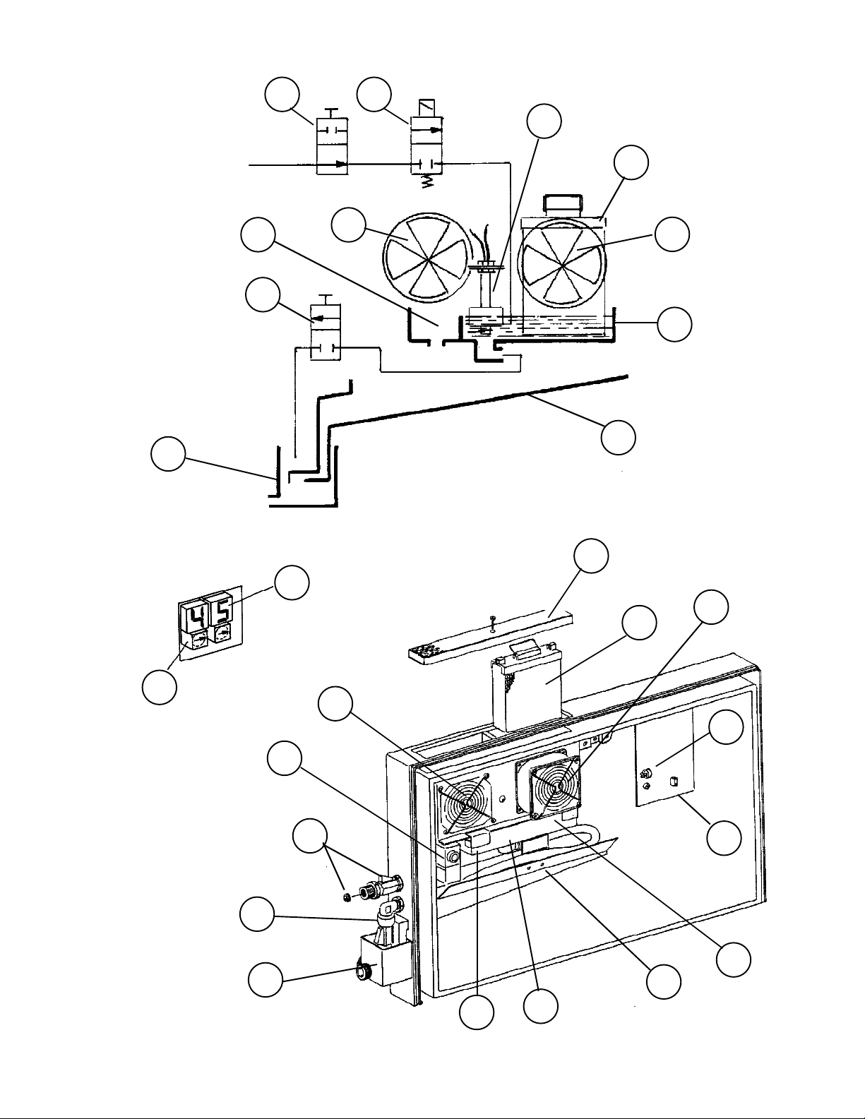
The HUMIDIFIER contains the following parts. See the DIAGRAMS on the opposite page.
1) A water supply MANUAL VALVE - this VALVE incorporates a RESTRICTOR which can be removed
if using a low pressure supply - such as a BOTTLE.
2) A water inlet SOLENOID VALVE which is energised when the HUMIDIFIER requires water.
3) A water level FLOAT SWITCH which controls the water level in the WATER BATH.
4) A WATER BATH to hold water for the PAPER ELEMENT.
5) A PAPER ELEMENT which draws water up in front of the WET FAN.
6) A WET FAN which is switched on when the humidity level inside the MINILOADER is lower than the SET
POINT.
7) A DRY FAN which runs when the WET FAN is switched off to maintain a positive pressure in the
MINILOADER.
8) An OVERFLOW DRAIN which operates if the water level control fails.
9) A SAFETY OVERFLOW CHUTE which prevents water entering the MINILOADER.
10)A MANUAL DRAIN VALVE which allows the drainage of the HUMIDIFIER for service or machine
transport.
11)A DRAIN HEADER which collects all water from the OVERFLOWS and the DRAIN VALVE.
This DRAIN HEADER MUST be connected to a customer drain or a bottle if the water supply is from a
bottle.
12) A HUMIDITY SENSOR which measures the humidity inside the MINILOADER.
13) A MICROPROCESSOR CONTROL PCB which monitors and controls the functions of the
HUMIDIFIER.
14) A two digit DISPLAY which shows the current HUMIDITY inside the MINILOADER.
15) CONTROL SWITCHES which are used to set the desired humidity level.
16) An AIR FILTER to prevent dust entering the HUMIDIFIER.
© Kodak Ltd.
Page XP/2-4
March 1995
Page 5
HUMIDIFIER ASSEMBLY
XP 3239-2
1 2
3
WATER IN
11
DRAIN
8
10
5
7
6
4
WATERFLO.TIF
9
16
15
M8_FIG7.TIF
10
11
14
2
6
5
7
12
1
13
4
9
March 1995
Page XP/2-5
8
3
M8_FIG10.TIF
© Kodak Ltd.
Page 6

XP 3239-2 HUMIDIFIER ASSEMBLY
INSTALLATION INSTRUCTIONS.
WATER SUPPLY
The incoming water supply specification is:-
PRESSURE RANGE 0.3 to 5 Bar. Install a REGULATOR if required.
TEMPERATURE 4 to 29 oC Tempered water required if temperature of incoming water is below 4 oC.
VOLUME APPROX. 1Lite per 24 hours approximately (depending on room humidity).
A 50 micron WATER FILTER should be provided by the customer.
Connect the water supply to the WATER INLET. If a BOTTLE is being used to supply the inlet water, the
RESTRICTOR should be removed. If the water supply is at mains pressure, the RESTRICTOR MUST be fitted,
otherwise water can splash inside the MINILOADER when the SOLENOID VALVE opens.
The drain must be connected. Normally water only flows from the unit when the HUMIDIFIER is drained for service
purposes or if the MINILOADER is to be moved, but in the event of a failure of the SOLENOID VALVE the drain is
required to have a capacity of 1 Litre/minute.If the water supply is at mains, the drain should be connected to a fixed
customer drain.
If the water supply is from a BOTTLE, a larger size collecting BOTTLE than the inlet BOTTLE should be used.
IMPORTANT:- If the MINILOADER is in a mobile unit, or is mounted on a movable STAND, the customer
must be informed that the water must be turned off and the HUMIDIFIER drained using the DRAIN VALVE,
before the MINILOADER is moved. If the MINILOADER is not going to be used for some time, it is advisable
to drain the HUMIDIFIER of water to prevent bacterial growth in the PAPER ELEMENT.
When the MINILOADER is switched on, the HUMIDIFIER is also turned on. The DISPLAY will show the current
humidity inside the MINILOADER. If the humidity inside the MINILOADER is greater than the preset value, only the
DRY FAN will run. If the humidity is below the preset value, the SOLENOID VALVE opens, the DRY FAN stops and
the WET FAN starts to increase the humidity.
If the humidity inside the MINILOADER is different (either higher or lower) from the preset value after 10 minutes, the
figures on the DISPLAY will flash. If the humidity inside is higher than the preset value nothing can be done, but if the
humidity is lower, check the water supply, FLOAT VALVE and the PAPER ELEMENT.
The speed of the WET and DRY FANS (and therefore the noise made by them) can be controlled.
For LOW VOLTAGE machines the speed is contolled by POTENTIOMETERS on PCB 207. The recomended setting
is R730 (for the DRY FAN) turn fully clockwise then back 5 turns anf R728 (for the WET FAN) turn fully clockwise
then back 3 turns.
For KIT HUMIDIFIERS the speed of both FANS are adjusted at the same time by a POTENTIOMETER mounted on
the FAN ASSEMBLY. See the drawing on PAGE XP/2-26.
© Kodak Ltd.
Page XP/2-6
March 1995
Page 7
HUMIDIFIER ASSEMBLY
XP 3239-2
SERVICE
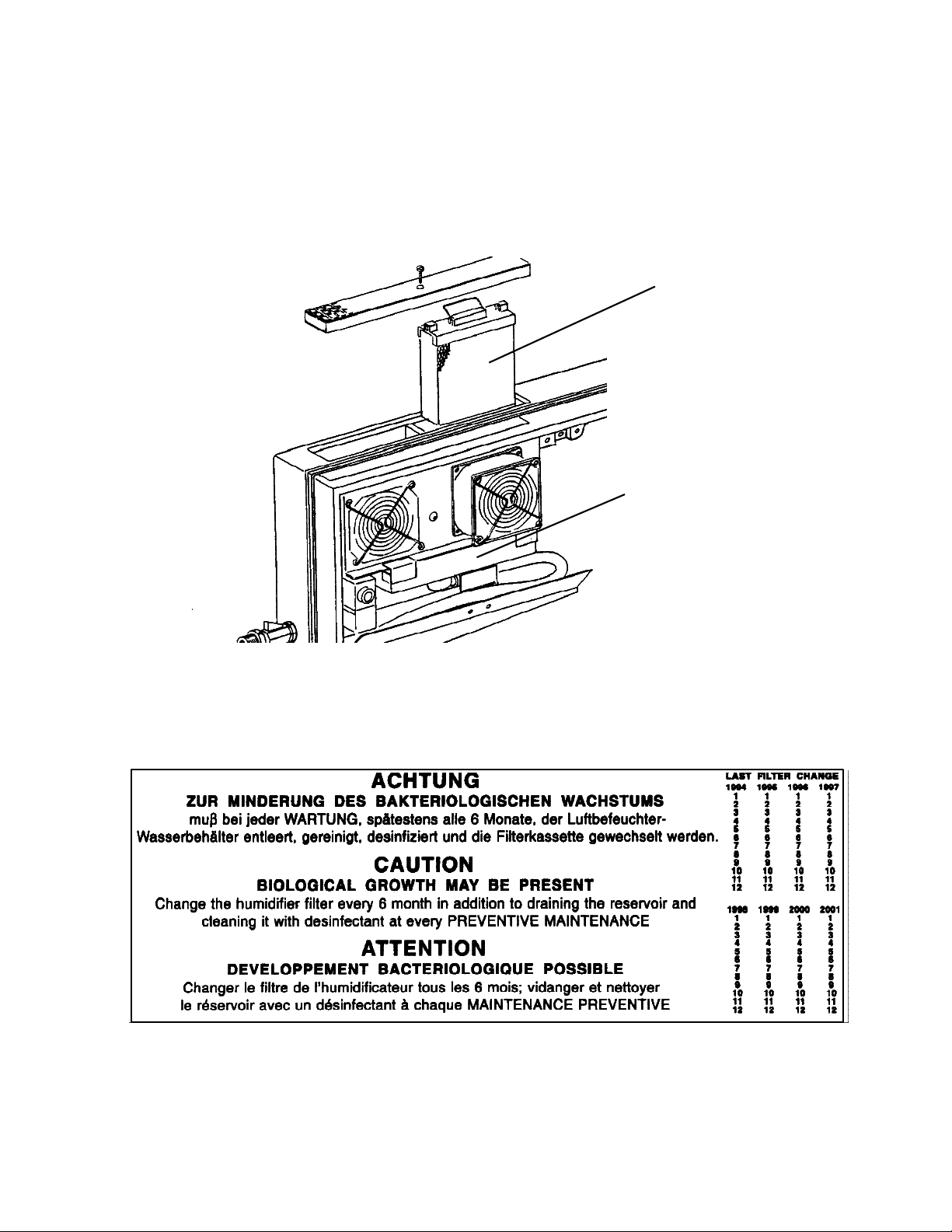
Routine service of the HUMIDIFIER requires that the unit is thoroughly cleaned out when a PM (Preventative
Maintenance) CALL is carried out. Disinfectant or bleach should be used. The PAPER ELEMENT should be changed
if necessary, and must be changed if it is more than six months old. The LABEL inside the HUMIDIFIER should be checked
with the date of the ELEMENT change.
Replace ELEMENT
Clean out WATER BATH
M8_FIG10.TIF
LABEL.TIF
March 1995
Page XP/2-7
© Kodak Ltd.
Page 8
XP 3239-2 HUMIDIFIER ASSEMBLY
IMPORTANT. If the HUMIDIFIER supplied with a new LOW VOLTAGE MINILOADER, the
PCB will be PCB 208. If the HUMIDIFIER was fitted as a modification, the PCB will be PCB 209.
The two PCB's are NOT interchangable.
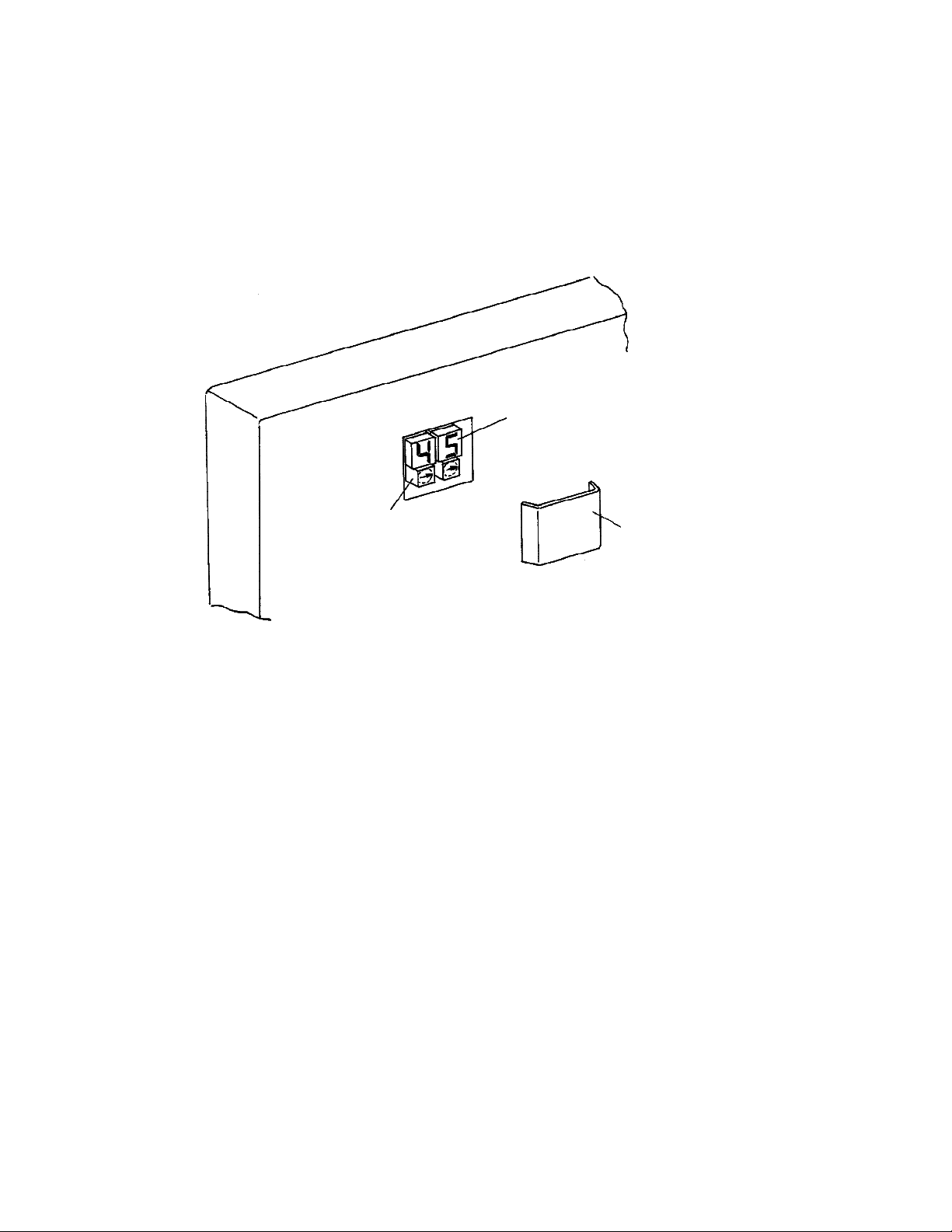
To alter the humidity setting, remove the clear plastic COVER and set the SELECTOR SWITCHES to the desired
humidity. The recommended preset is 45% RH. Replace the COVER.
DISPLAY
SELECTOR SWITCHES
COVER
M8_FIG7.TIF
When the MINILOADER is powered up, the HUMIDIFIER will switch on automatically. If the humidity inside the
MINILOADER is greater than the preset value, only the DRY FAN will run. If the humidity is below the preset value,
the INLET WATER VALVE opens, the DRY FAN stops and the WET FAN starts to increase the humidity inside the
MINILOADER.
IMPORTANT :- If the humidity inside the MINILOADER is different (either higher or lower) from the preset value after
10 minutes, the figures on the DISPLAY will flash. If the humidity is higher than the preset nothing can be done, but if
the humidity is lower, check the water supply, FLOAT VALVE and the FILTER ELEMENT.
The calibration of the HUMIDITY SENSOR is factory set, but if a HUMIDITY METER (29050132) is available the
calibration of the DISPLAY can be adjusted. After the unit has stabilised (after 30 minutes), measure the humidity inside
the MINILOADER by inserting the PROBE of the HUMIDITY METER through the ENTRY SLOT. Compare the
reading on the HUMIDITY METER with the HUMIDIFIER DISPLAY. If necessary the HUMIDIFIER DISPLAY
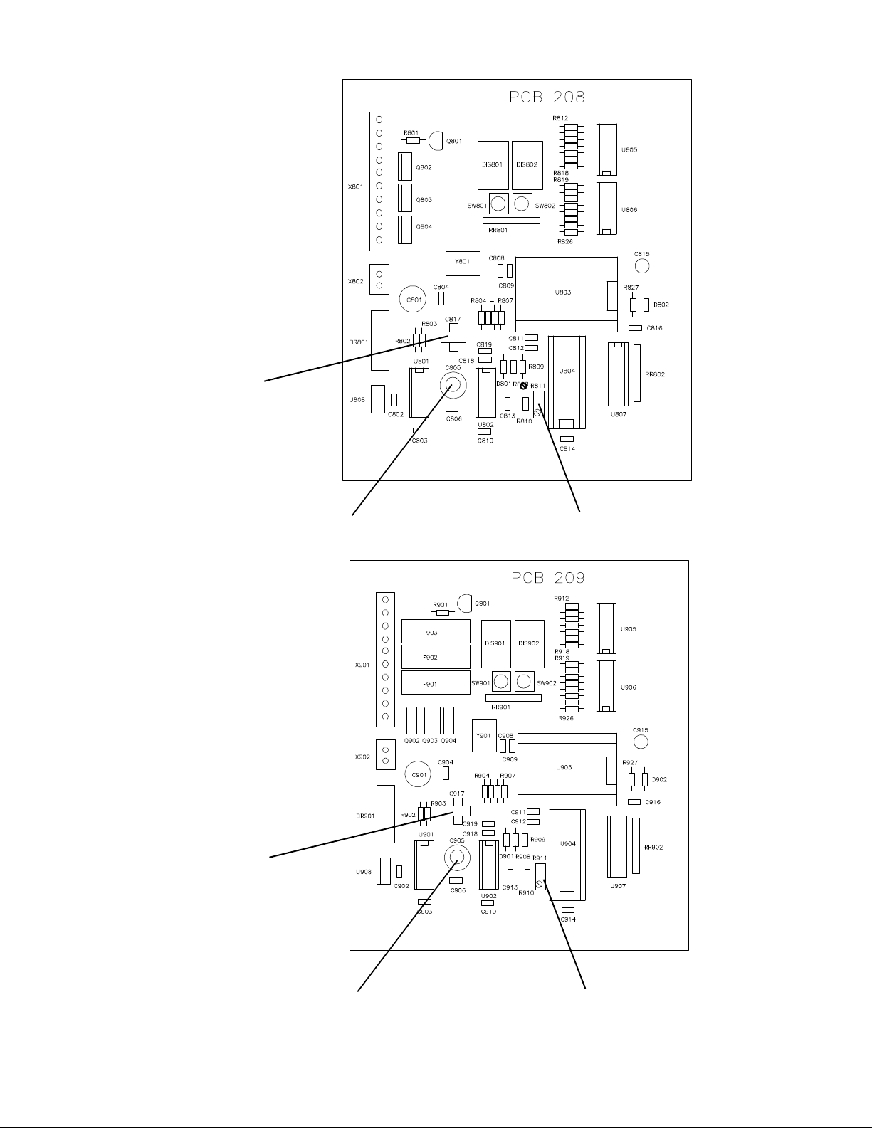
reading can be adjusted by POTENTIOMETER R11 on the HUMIDIFIER PCB 209. See FIGURE 9.
IMPORTANT - DO NOT TOUCH THE VARIABLE CAPACITOR OR YOU WILL ALTER THE FACTORY
SETTING.
© Kodak Ltd.
Page XP/2-8
March 1995
Page 9
HUMIDIFIER ASSEMBLY
PCB 208
LOW VOLTAGE
MACHINES ONLY
HUMIDITY SENSOR
XP 3239-2
PCB208.PIC
CALIBRATION - DO NOT TOUCH - FACTORY SET
PCB 209
KIT HUMIDIFIERS
ONLY
HUMIDITY SENSOR
DISPLAY ADJUSTMENT
PCB209.PIC
March 1995
CALIBRATION - DO NOT TOUCH - FACTORY SET
Page XP/2-9
DISPLAY ADJUSTMENT
© Kodak Ltd.
Page 10
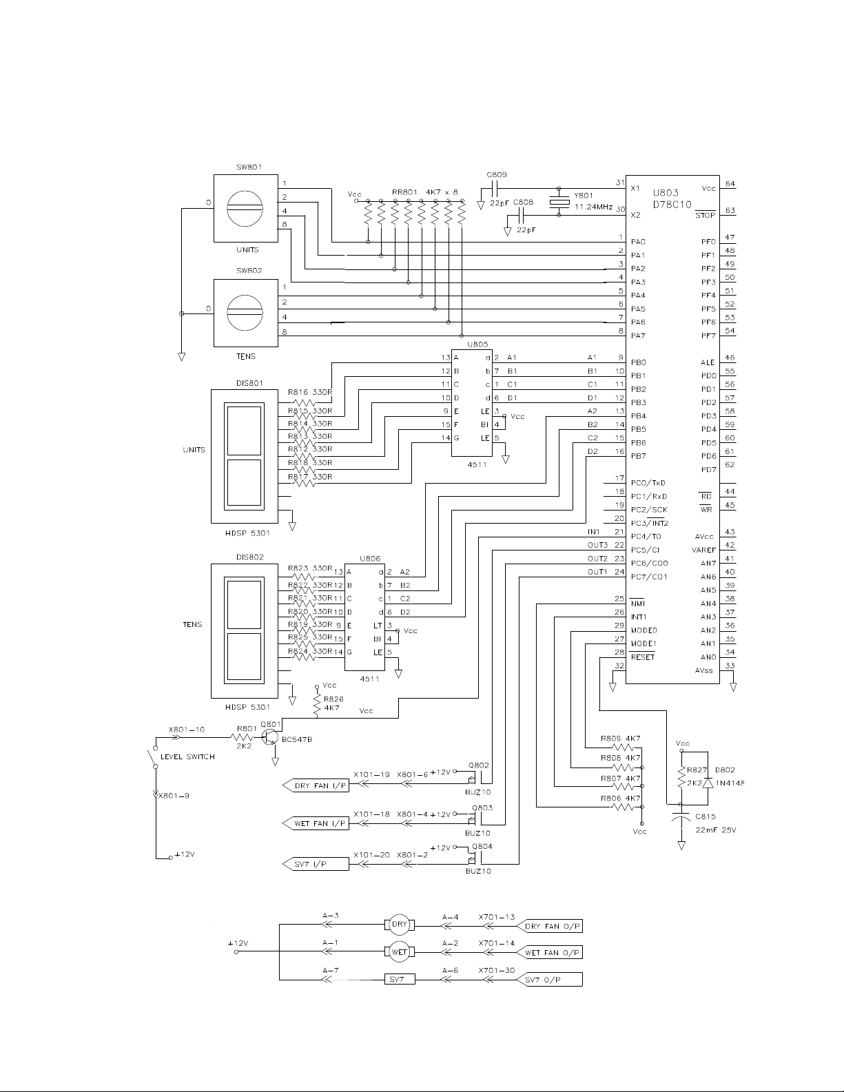
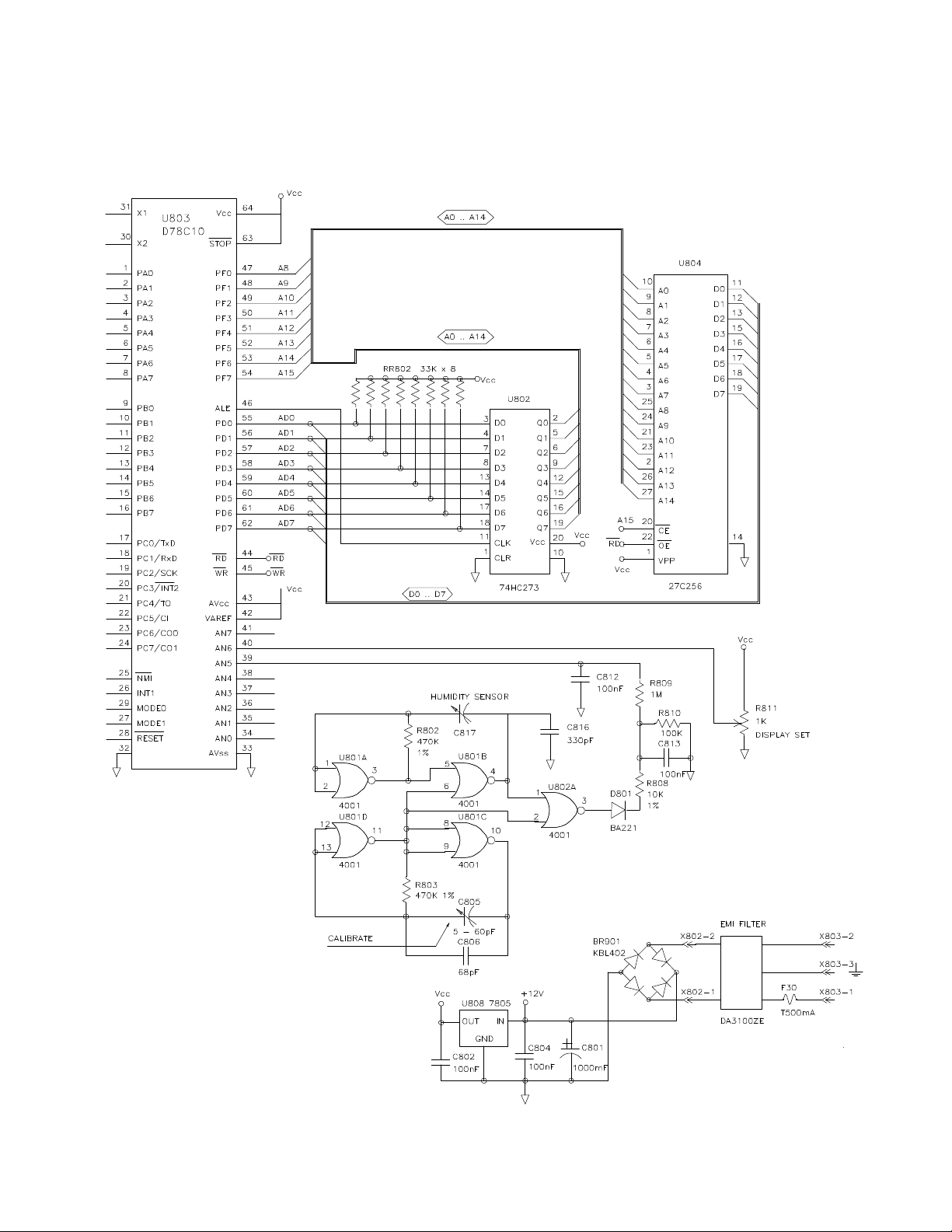
XP 3239-2 HUMIDIFIER ASSEMBLY
PCB 208 (LOW VOLTAGE MACHINE HUMIDIFIERS ONLY)
PCB208L.PIC
© Kodak Ltd.
Page XP/2-10
March 1995
Page 11
HUMIDIFIER ASSEMBLY
XP 3239-2
PCB 208 (LOW VOLTAGE MACHINE HUMIDIFIERS ONLY)
March 1995
Page XP/2-11
PCB208R.PIC
© Kodak Ltd.
Page 12

XP 3239-2 HUMIDIFIER ASSEMBLY
PCB 209 (KIT HUMIDIFIERS ONLY)
© Kodak Ltd.
Page XP/2-12
PCB209L.PIC
March 1995
Page 13

HUMIDIFIER ASSEMBLY
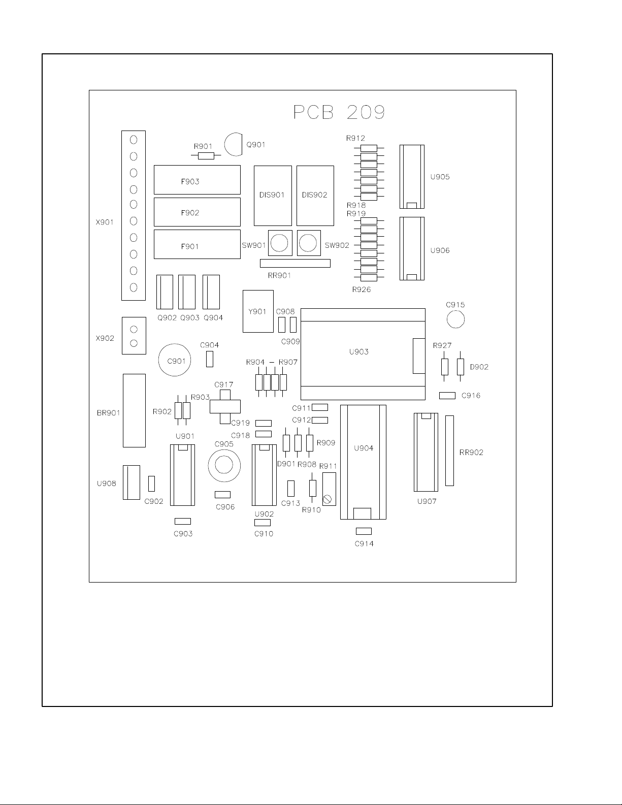
PCB 209 (KIT HUMIDIFIERS ONLY)
XP 3239-2
March 1995
Page XP/2-13
PCB209R.PIC
© Kodak Ltd.
Page 14

XP 3239-2 HUMIDIFIER ASSEMBLY
PCB 208 (LOW VOLTAGE MACHINE HUMIDIFIERS ONLY)
COMPONENT OVERLAY
© Kodak Ltd.
Page XP/2-14
PCB208.PIC
March 1995
Page 15

HUMIDIFIER ASSEMBLY
XP 3239-2
PCB 209 (KIT HUMIDIFIERS ONLY)
COMPONENT OVERLAY
March 1995
Page XP/2-15
PCB209.PIC
© Kodak Ltd.
Page 16

XP 3239-2 HUMIDIFIER ASSEMBLY
1
19
6
7
5
4
2
3
8
9
18
16
17
15
HUMIDIFIER ASSEMBLY
FIG A
© Kodak Ltd.
14
13
Page XP/2-16
10
11
12
PARTS1.TIF
March 1995
Page 17

HUMIDIFIER ASSEMBLY
KEY P AR T NO DESCRIPTION
1 30027208 ELBOW
2 30027129 FITTING, INLET
3 30027213 SEAL, "O" RING
4 30027217 NUT , M20
5 30027200 SOLENOID VAL VE, WA TER INLET, 12 VOL T
6 30015592 ELBOW , 1/8"
7 30015590 TUBE, RIGID, 5 x 3 mm
8 30015563 NUT , M3
XP 3239-2
9 30025818 WASHER, M4 x 12
10 30027130 FITTING, OUTLET
11 30027122 DRAIN HEADER
12 30027221 SCREW, CROSS HEAD, M3 x 25
13 30027215 PLUG, 3/8"
14 30027209 PIPE, 10 x 14 mm
15 30027216 ADAPTOR, 3/4" x 15 mm
16 30027206 VAL VE, DRAIN
17 30027126 RESTRICTOR
18 30027204 REDUCER, 3/4" M x 3/8" F
19 30027205 VAL VE, WATER INLET
March 1995
Page XP/2-17
HUMIDIFIER ASSEMBLY
FIG A
© Kodak Ltd.
Page 18

XP 3239-2 HUMIDIFIER ASSEMBLY
2
1
3
4
5
15
14
13
6
7
8
9
10
11
12
HUMIDIFIER ASSEMBLY
FIG B
© Kodak Ltd.
Page XP/2-18
PARTS2.TIF
March 1995
Page 19

HUMIDIFIER ASSEMBLY
KEY P AR T NO DESCRIPTION
1 30027221 SCREW, CROSS-HEADED, M3 x 25
2 30027112 COVER, FILTER
3 30027113 FIL TER, AIR
4 3002711 1 SUPPOR T , FILTER
5 30025818 WASHER, M4 INTERNAL, M12 EXTERNAL
6 30015611 SCREW , HEX-HEADED, M3 x 6
7 30027128 COVER, DISPLAY
8 30027141 GUARD, PCB 208/209
XP 3239-2
9 30025813 SCREW, HEX-HEADED, M4 x 6
10 30015685 STUD, M4 x 10
11 30015564 NUT, M4
12 30027140 SUPPOR T, PCB, MINI 2 & 2 PLUS ONL Y
30027139 SUPPOR T, PCB, MINI 1 & 1M ONL Y
13 30015682 SCREW, HEX-HEADED, M3 x 8
14 30027103 HOUSING - MODEL M35-M ONLY
30027104 HOUSING - MINI 2 & 2 PLUS MODEL SA & 480RA
30027105 HOUSING - MINILOADER 1 & 1M ONLY
15 30027202 FILTER CARTRIDGE
IMPORTANT - MAKE SURE YOU ORDER THE CORRECT PARTS FOR THE VERSION
OF HUMIDIFIER THAT IS FITTED TO THE MINILOADER
March 1995
Page XP/2-19
HUMIDIFIER ASSEMBLY
FIG B
© Kodak Ltd.
Page 20

XP 3239-2 HUMIDIFIER ASSEMBLY
4
2
3
5
6
1
8
7
12
9
13
4
14
23
15
22
9
21
HUMIDIFIER ASSEMBLY
FIG C
20
19
18
17
16
10
11
PARTS3.TIF
© Kodak Ltd.
Page XP/2-20
March 1995
Page 21

HUMIDIFIER ASSEMBLY
KEY P AR T NO DESCRIPTION
1 30015557 SCREW, CROSS-HEAD, COUNTERSUNK, M3 x 10
2 30027210 CONNECTOR, HOSE
3 30027211 ADAPTOR
4 30015556 SCREW , CROSS-HEAD COUNTERSUNK, M3 x 6
5 30027222 SCREW , SELF-TAPPING, 3.5 x 6.5 mm
6 30025851 SCREW , CROSS-HEAD, SELF-TAPPING, 3.9 x 13 mm
7 30027110 SUPPORT, VERSION M35-M ONL Y
8 30015568 WASHER, FLAT , M3
XP 3239-2
9 30015563 NUT , M3
10 30026615 PCB 208 (LOW VOLTAGE MINILOADER ONL Y)
30027132 PCB 209 (FOR ALL KIT HUMIDIFIERS)
11 30027142 PROTECTION, PCB 208/209
12 30015956 CONNECTOR, FEMALE, 9 PIN
13 30027146 BRACKET , CONNECT OR SUPPORT
14 30015955 CONNECTOR, MALE, 9 PIN
15 30027137 BRACKET , ELEMENT SUPPORT
16 30025818 WASHER, M4 INTERNAL, M12 EXTERNAL
17 30015564 NUT, M4
18 30027107 SUPPOR T
19 30027127 NIPPLE
20 30027201 SENSOR, WA TER LEVEL
21 30027207 NUT, M17
22 30015569 WASHER M4
23 30027147 INLET , WATER
March 1995
Page XP/2-21
HUMIDIFIER ASSEMBLY
FIG C
© Kodak Ltd.
Page 22

XP 3239-2 HUMIDIFIER ASSEMBLY
4
5
3
1
6
2
7
8
8
9
9
8
16
15
3
10
1
11
11
14
13
12
9
10
HUMIDIFIER ASSEMBLY
FIG D
© Kodak Ltd.
Page XP/2-22
PARTS4.TIF
PARTS4A.TIF
March 1995
Page 23

HUMIDIFIER ASSEMBLY
XP 3239-2
KEY P AR T NO DESCRIPTION
1 30027203 F AN, 12 VOLT
2 30015557 SCREW , CROSS-HEADED, COUNTERSUNK, M3 x 10
3 30015556 SCREW , CROSS-HEADED, COUNTERSUNK, M3 x 6
4 30027120 GUIDE, FILTER
5 30027106 SUPPORT, FAN
6 30025851 SCREW , SELF TAPPING, 3.9 x 13
7 30027116 FIXING, TRA Y, RIGHT
8 30015563 NUT , M3
9 30015568 WASHER, FLAT , M3
10 30025106 SCREW, HEX-HEADED, M3 x 14
11 30015523 GRID, F AN
12 30015552 SCREW, CROSS-HEAD, M3 x 16
13 30015682 SCREW, HEX-HEAD, M3 x 8
14 30027218 CONNECTOR BLOCK
15 30027214 GROMMET, 7 mm
16 300271 17 FIXING, TRA Y, LEFT
March 1995
Page XP/2-23
HUMIDIFIER ASSEMBLY
FIG D
© Kodak Ltd.
Page 24

XP 3239-2 HUMIDIFIER ASSEMBLY
20
19
21
4
2
3
5
6
7
8
1
9
10
12
11
10
13
7
18
16
17
HUMIDIFIER ASSEMBLY
FIG E
© Kodak Ltd.
15
11
Page XP/2-24
14
24
22
23
PARTS5.TIF
March 1995
Page 25

HUMIDIFIER ASSEMBLY
KEY P AR T NO DESCRIPTION
1 30027109 TRA Y, WATER
2 30027125 FITTING
3 30027123 FITTING
4 30027148 PROTECTION PLATE
5 30027131 LABEL, HUMIDIFIER
6 30015682 SCREW, HEX-HEADED, M3 x 8
7 30015568 WASHER, FLAT , M3
8 30027115 BRACKET
9 30027119 BRACKET
XP 3239-2
10 30015563 NUT, M3
11 30015537 SCREW, HEX-HEADED, M4 x 10
12 30027108 OVERFLOW TRAY
13 30025812 SCREW, HEX-HEADED, M3 x 20
14 30015564 NUT , M4
15 30027145 STOP, LIGHT PROTECTION (KIT HUMIDIFIER ONLY)
16 30027149 PROTECTION, METAL PANEL HUMIDIFIERS ONL Y
17 30027150 PROTECTION, METAL P ANEL HUMIDIFIERS ONLY
18 30027143 BLOCK, RUBBER (KIT HUMIDIFIER ONLY)
19 30027144 BRACKET (KIT HUMIDIFIER ONLY)
20 30027209 TUBE, 10 x 14
21 30027212 SEAL, "O" RING
22 300271 18 ADAPTOR PLATE, MODEL M35-M ONL Y
23 30015565 NUT , M5
24 30025825 SCREW, CROSS HEADED, COUNTERSUNK, M5 x 10
March 1995
Page XP/2-25
HUMIDIFIER ASSEMBLY
FIG E
© Kodak Ltd.
Page 26

XP 3239-2 HUMIDIFIER ASSEMBLY
HUMIDIFIER
PARTS6A.TIF
11
10
1
12
2
PCB 208
3
4
5
6
9
LOW VOLTAGE MACHINE ONLY
8
7
13
HUMIDIFIER
9
PARTS6B.TIF
HUMIDIFIER ASSEMBLY
FIG F
3
PCB 209
4
5
14
7
8
HUMIDIFIER KITS ONLY
© Kodak Ltd.
Page XP/2-26
March 1995
Page 27

HUMIDIFIER ASSEMBLY
XP 3239-2
KEY P AR T NO DESCRIPTION
1 30027135 CABLE, PCB 208 TO 207 - LOW VOL T AGE MACHINE ONLY
2 30026615 PCB 208 - LOW VOL T AGE MACHINE ONLY
3 30027227 FIL TER, EMI, ARCOTRONICS
4 30027226 FIL TER/FUSE ASSEMBLY COMPLETE
5 30027224 FUSEHOLDER, OMEGA K1010
6 30027225 FUSE, T500 mAMP , 5 x 20 mm
7 30027229 PLUG, MALE, 4 POLE
8 30027228 PLUG, FEMALE, 4 POLE
9 30027133 CABLE, TRANSFORMER TO EMI FILTER
10 30027136 CABLE, PCB 207 TO HUMIDIFIER - LOW VOLT AGE
MACHINE ONLY
11 30027223 POTENTIOMETER 47 R, 5 WA TT - KIT HUMIDIFIER ONLY
12 30027134 CABLE PCB 209 TO HUMIDIFIER - KIT HUMIDIFIER ONLY
13 30027132 PCB 209 - KIT HUMIDIFIER ONLY
14 30025644 FUSE, T2 AMP, 5 x 20 mm
IMPORTANT - MAKE SURE YOU ORDER THE CORRECT PARTS FOR THE VERSION
OF HUMIDIFIER THAT IS FITTED TO THE MINILOADER
March 1995
Page XP/2-27
HUMIDIFIER ASSEMBLY
FIG F
© Kodak Ltd.
Page 28

XP 3239-2 HUMIDIFIER ASSEMBLY
HUMIDIFIER ASSEMBLY
FIG G
© Kodak Ltd.
Page XP/2-28
PCB208.PIC
March 1995
Page 29

HUMIDIFIER ASSEMBLY
KEY P AR T NO DESCRIPTION
PCB 208 30026615 PCB 208 - LOW VOLT AGE MACHINE ONLY
BR801 30026630 DIODE BRIDGE, KBU604
C805 30026649 CAPACITOR, VARIABLE, 3 - 60 pF
C817 30026647 SENSOR, HUMIDITY, PHILLIPS
DIS801, 802 30026656 DISPLAY, COMMON CATHODE
Q801 30025520 TRANSISTOR, NPN, BC547
Q802, 3, 4 30026626 TRANSISTOR. MOSFET, BUZ10
XP 3239-2
U801, 802 30026642 INTEGRATED CIRCUIT , 4001, QUAD 2 INPUT NOR
U803 30025505 INTEGRATED CIRCUIT , MICROPROCESSOR , 78C10
U804 30027220 INTEGRATED CIRCUIT , EPROM, V. HUMIDIFIER 01
U805, 806 30026643 INTEGRATED CIRCUIT , 4511, BCD TO 7 SEG DRIVER
U807 30025508 INTEGRATED CIRCUIT , BUFFER, 74HC373
U808 30025523 INTEGRATED CIRCUIT , 7805, VOLT AGE REG.
IMPORTANT - MAKE SURE YOU ORDER THE CORRECT PARTS FOR THE VERSION
OF HUMIDIFIER THAT IS FITTED TO THE MINILOADER
March 1995
Page XP/2-29
HUMIDIFIER ASSEMBLY
FIG G
© Kodak Ltd.
Page 30
XP 3239-2 HUMIDIFIER ASSEMBLY
HUMIDIFIER ASSEMBLY
FIG H
© Kodak Ltd.
Page XP/2-30
PCB209.PIC
March 1995
Page 31

HUMIDIFIER ASSEMBLY
KEY P AR T NO DESCRIPTION
PCB 209 30027132 PCB 209 - HUMIDIFIER KITS ONLY
BR901 30026630 DIODE BRIDGE, KBU604
C905 30026649 CAPACITOR, VARIABLE, 3 - 60 pF
C917 30026647 SENSOR, HUMIDITY, PHILLIPS
DIS901, 902 30026656 DISPLAY, COMMON CATHODE
F901, 2, 3 30025642 FUSE, 5 x 20 mm, T1A
30025591 FUSEHOLDER, PCB TYPE
Q901 30025520 TRANSISTOR, NPN, BC547
XP 3239-2
Q902, 3, 4 30026626 TRANSISTOR. MOSFET, BUZ10
U901, 902 30026642 INTEGRATED CIRCUIT , 4001, QUAD 2 INPUT NOR
U903 30025505 INTEGRATED CIRCUIT , MICROPROCESSOR , 78C10
U904 30027220 INTEGRATED CIRCUIT , EPROM, V. HUMIDIFIER 01
U905, 906 30026643 INTEGRATED CIRCUIT , 4511, BCD TO 7 SEG DRIVER
U907 30025508 INTEGRATED CIRCUIT , BUFFER, 74HC373
U908 30025523 INTEGRATED CIRCUIT , 7805, VOLT AGE REG.
IMPORTANT - MAKE SURE YOU ORDER THE CORRECT PARTS FOR THE VERSION
OF HUMIDIFIER THAT IS FITTED TO THE MINILOADER
March 1995
Page XP/2-31
HUMIDIFIER ASSEMBLY
FIG H
© Kodak Ltd.
Page 32

XP 3239-2 HUMIDIFIER ASSEMBLY
THIS PAGE IS INTENTIONALY LEFT BLANK
© Kodak Ltd.
Page XP/2-32
March 1995
Page 33

HUMIDIFIER ASSEMBLY
Rev. Date PCN No. Pub.No. Affected Pages Description
XP 3239-2
October 94
November 94
1 300800xx 9, 14,15, 28, &
30
26,27
Corrected drawings of PCB 208 & 209
overlays.
Added POTENTIOMETER to drawing
and text.
March 1995
Page XP/2-33
© Kodak Ltd.
Page 34

HEAL TH SCIENCES DIVISION
© Kodak Ltd., Customer Equipment Services Division, Swallowdale Lane, Hemel Hempstead, Hertfordshire, England.
 Loading...