

Page 1

Document Scanner/
Microimager 990
A-61096
Part No. 1E8015
User’s
Guide
Page 2

1 Introduction
The
Kodak Digital Science
microfilm and electronically scan documents simultaneously. The
scanner/microimager is designed for productive throughput in mediumto high-volume applications accommodating a variety of document
sizes.
Each mode can be configured to film and scan documents
simultaneously or film documents only (no scan). In addition, certain
modes may be configured to scan documents only (no film). Details of
the no film/no scan mode are provided in this manual.
Document Scanner/Microimager 990 can
Scanner features
The Document Scanner/Microimager 990 has the following features:
• A high-speed document transport system.
• Automatic exposure control, which calculates proper microfilm
exposure settings.
• Excellent image quality, with a choice of 24X, 40X, or 50X
reduction ratios.
• A two-line 80-character display for status information and operator
messages.
• Easy-to-reach control panel keys, identified by graphic symbols.
• Full programmability of 18 application modes, with override
capability.
• Linked modes may be used to carry over the image address from
one mode to another.
• Programmable keys to perform commonly-used functions.
• Transport-on functions, which allow some function codes to be
executed while the transport is running.
• Film cassettes with memory capability; one or two cassettes may
be used, according to user requirements.
A-61096 June 1999 1-1
• Custom image mark sizing.
• Audible tones for selected functions, such as the footswitch, patch
reading, etc.
• English or other language message display.
• A large, built-in workshelf.
• An adaptable, modular design for easy addition of accessories.
Page 3

Scanner/microimager
options
The following options are available for use with the scanner/
microimager:
• A choice of feeders, including a semi-automatic feeder or a check
feeder.
• A choice of exit hoppers, including a standard hopper or a check
stacker.
• A Footswitch for document level control.
• An Endorser for stamping information on documents.
• A 600 dpi, 12-character ink-jet printer which supports black and
magenta ink colors.
• A Patch Reader for automatic document level control.
• End-fed patch capability.
• A Bar Code Reader for decoding encoded information.
• A skew/length monitor.
• A film writing module for writing information on film next to
document images.
• A custom-designed chair (ergonomic design).
• A workstation console, left or right position.
1-2 A-61096 June 1999
Page 4
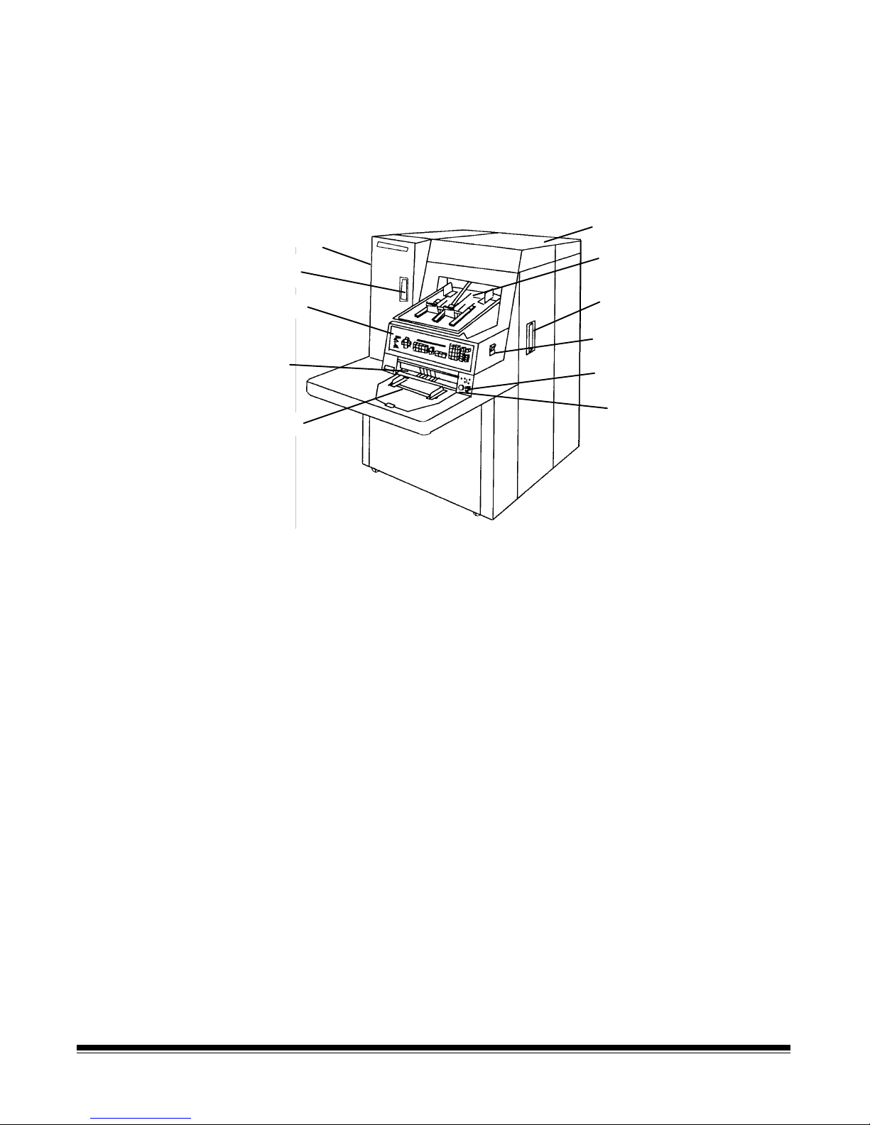
Scanner/microimager
components
The following illustrations and descriptions will help you locate and
become familiar with scanner/microimager components.
NOTE: The illustrations in this manual depict the scanner/microimager
990D, with the feeder/horizontal transport area brought
forward from the control panel.
Left-side access
Door (not shown)
Cassette
access door
Control panel
Feed and
separator
rollers
Feed tray
Left-side access door — provides access to the lens holder
assembly, mirrors, and other components.
Cassette access door — provides access to the film cassette
compartment.
Top cover
Exit hopper
Right-side access door
Side pane l switch
Gap release lever
Gap adjustment knob
Control panel — contains the status display, indicators, and operating
keys used to control the scanner/microimager.
Feed and separator rollers — provides smooth feeding of documents
of various sizes and textures.
Feed tray — holds documents prior to feeding.
Top cover — provides access behind the transport area
.
Exit hopper — collects documents after they have been scanned.
Right-side access door — provides access to the optical system,
transport system components and other components.
Side panel switch — allows you to turn the transport system on and
off.
Gap release lever — allows you to open the feed gap to allow thicker
documents to be fed into the transport.
Gap adjustment knob — allows you to manually adjust the space
between the feed and separator rollers for documents of varying
thicknesses.
A-61096 June 1999 1-3
Page 5
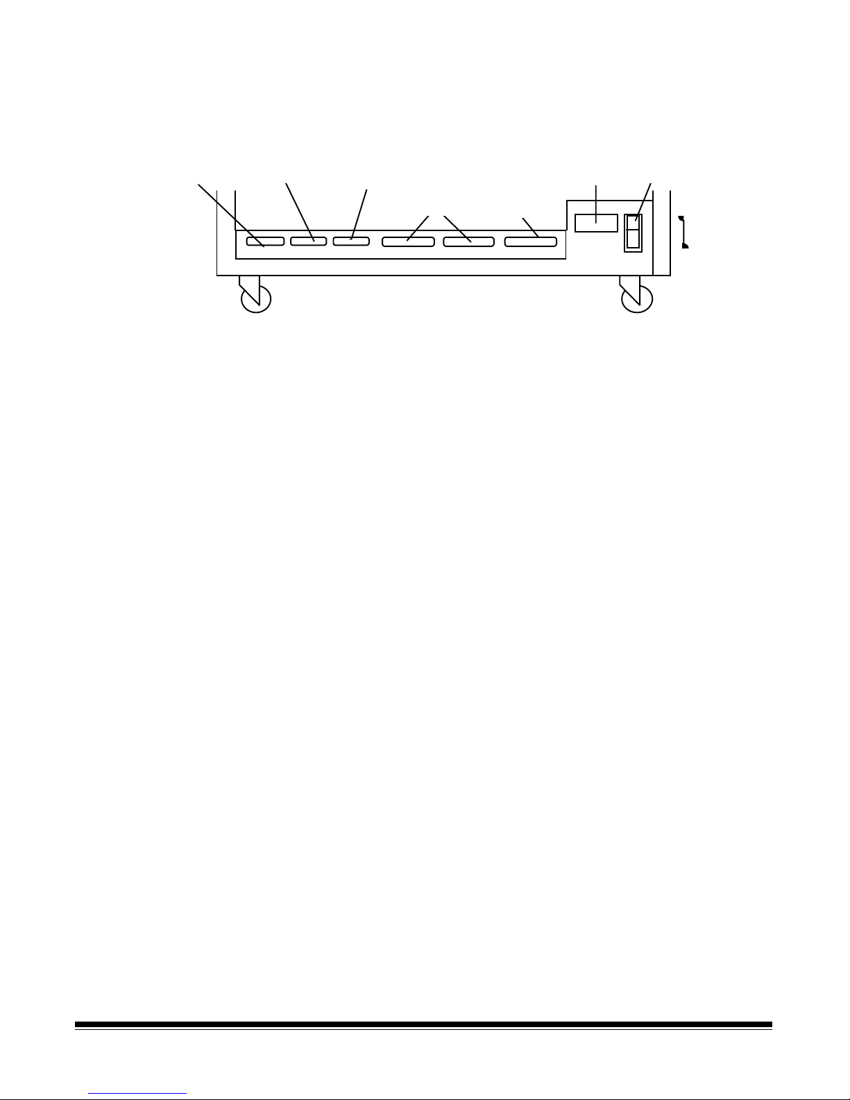
Rear view
Computer
interface 1
(COIN 1)
Computer
interface 2
(COIN 2)
J30 J31 J45 J32 J33 J46
Computer
interface 3
(COIN 3)
SCSI ports
Not Used
Power
cord
Main power switch
ON
OFF
Computer interface 1 (COIN1) — service/diagnostic interface.
Configures the scanner/microimager and runs diagnostics.
Computer interface 2 (COIN2) — OCR command/bar code interface.
Transfers commands between the scanner/microimager and external
devices/subsystems.
Computer interface 3 (COIN3) — SCSI diagnostic port interface.
System debugging and monitoring SCSI-host computer
communications.
SCSI ports — SCSI interface connection for the scanner/microimager.
Power cord — plugs into an appropriate power outlet.
Main power switch — turns main power to the scanner/microimager
on and off .
1-4 A-61096 June 1999
Page 6
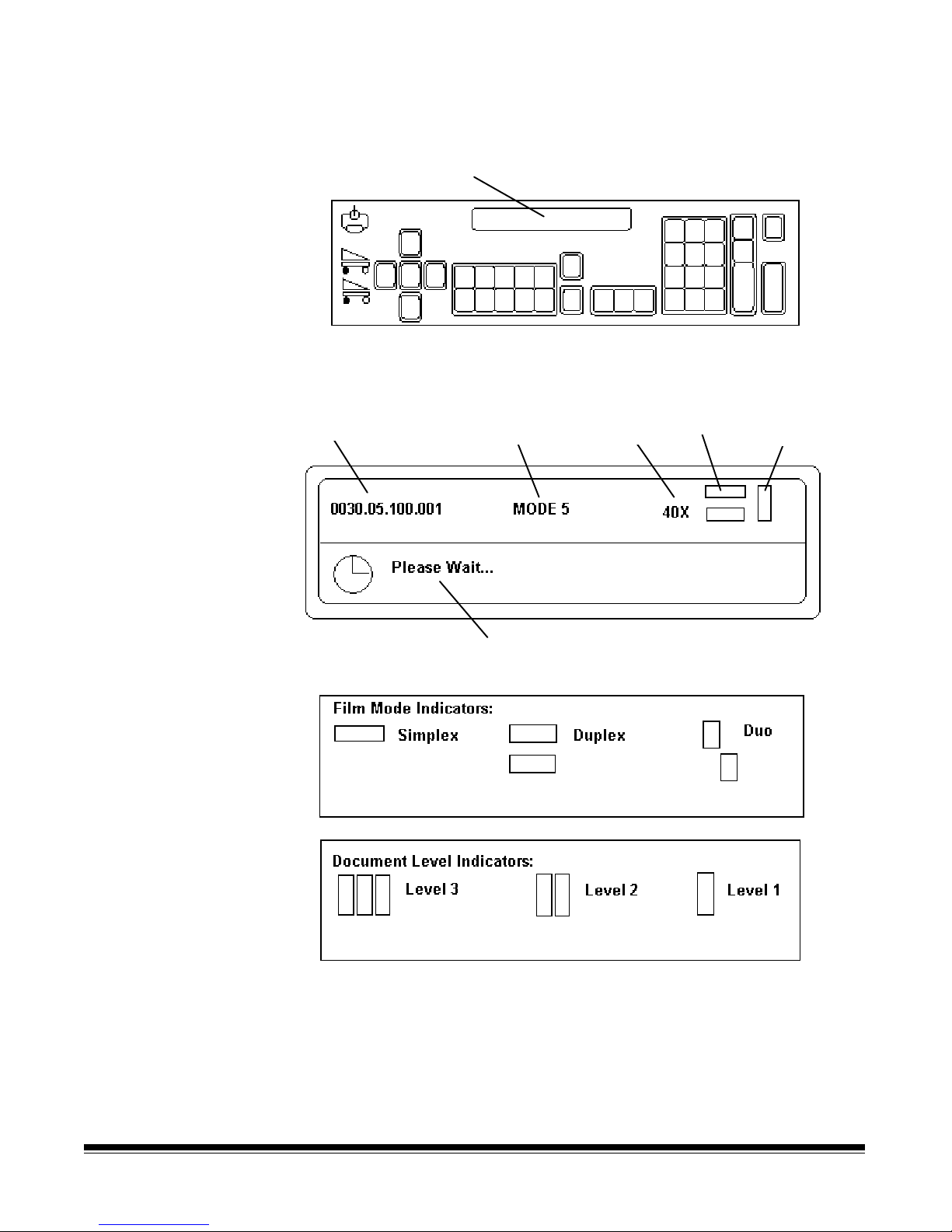
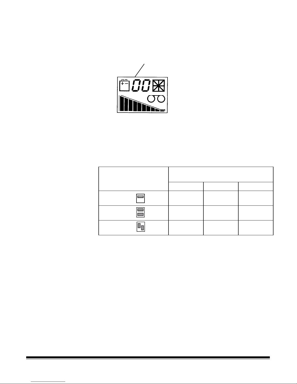
Status display — indicates the image address, scan mode, document
level and operator messages.
Two line status display
Image
address
Mode name/
number
Operator message
Lens
reduction
Film mode
indicator
Document
level
indicator
A-61096 June 1999 1-5
Page 7
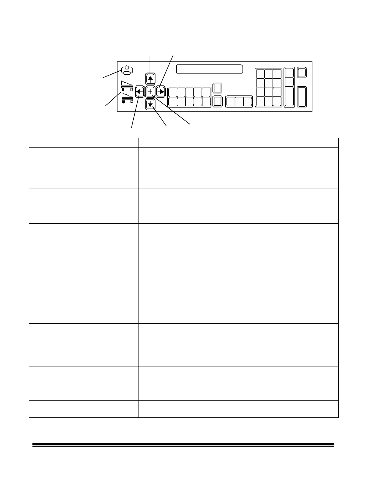
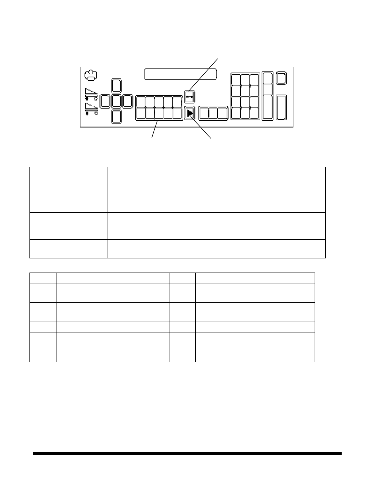
Operating keys and indicators
Right arrow
Plus key
Visual tone
display
Film supply
indicators
Left arrow
Up arrow
Downarrow
Key/Indicator Function
Visual tone display The upper and lower lights a re both illuminated whenever an
audio tone is issued. When using a Footswitch, the lower light is
illuminated and an audio tone is issued whenever the Footswitch
is pressed; while the upper light is illuminated (but no audio tone
is issued) when the Footswitch is released.
Up arrow (↑)
TheUparrowallowsyouto:
• Increment values at a faster rate.
• Increase a data value when used with certain functions.
• Enter an alpha character in the image address fixed field.
Right arrow (→)
The Right arrow allows you to:
• Increment values at a slower rate.
• Display additional messages in the status display. A blinking
cursor over the arrow in the display indicates there are
additional messages. Press the Right arrow key to display
these messages.
• Enter an alphanumeric character in the image address.
Film supply indicators Indicates how much film is available: A full cassette is indicated
by all lights in the display. An empty cassette is indicated by no
lights in the display. The upper indicator represents the film
supply in the upper cassette while the lower indicator represents
the film supply in the lower cassette.
Left arrow (←)
The Left arrow allows you to:
• Decrement values at a slower rate.
• Backspace, delete the last keystroke, or clear messages in
the status display.
• Enter an alphanumeric character in the image address.
Down arrow (↓)
TheDownarrowallowsyouto:
• Decrement values at a faster rate.
• Decrease a data value when used with certain functions.
• Enter an alpha character in the image address fixed field.
Plus key (+) Inputs a value for the image address. When pressed, it allows a
field to remain unchanged.
1-6 A-61096 June 1999
Page 8
Operating keys and indicators
3
5
Film advance
P1 P2
P7 P8
P6
Programmable keys
P
(P keys)
P4
P
P10
Jog key
Keys/Indicators Function
Film advance Advances film without making an exposure. Provides blank film
between images or at the end of a roll of film. Film is advanced as
long as the key is pressed (2.5 inches per second; or 0.5 inches if key
is pressed f or less than one second).
Programmable keys
(P keys)
Perform specific functions. The P keys have default values; any or all
of the defaults may be overridden/reprogrammed at installation. Use
the table below to record the functions performed by the P keys.
Jog Momentarily turns on (jogs) the transport system to help document
jams.
P Key Function (defaults indicated) P Key Function (defaults indicated)
P1
P2
F04, F02 Toggle Count Only
Mode
F45 Print Test
P6
P7
F30 Display Amount of Film
Remaining
F44 Omit Printing on Next
Document Only
P3
P4
F09 Total Document Count
F08 Display Last Image
P8
P9
F46 Print Position
F07 Level 0
Address
P5
F37 Calibrate
P10
A-61096 June 1999 1-7
F98, F38 Stop and End-of-job
Page 9
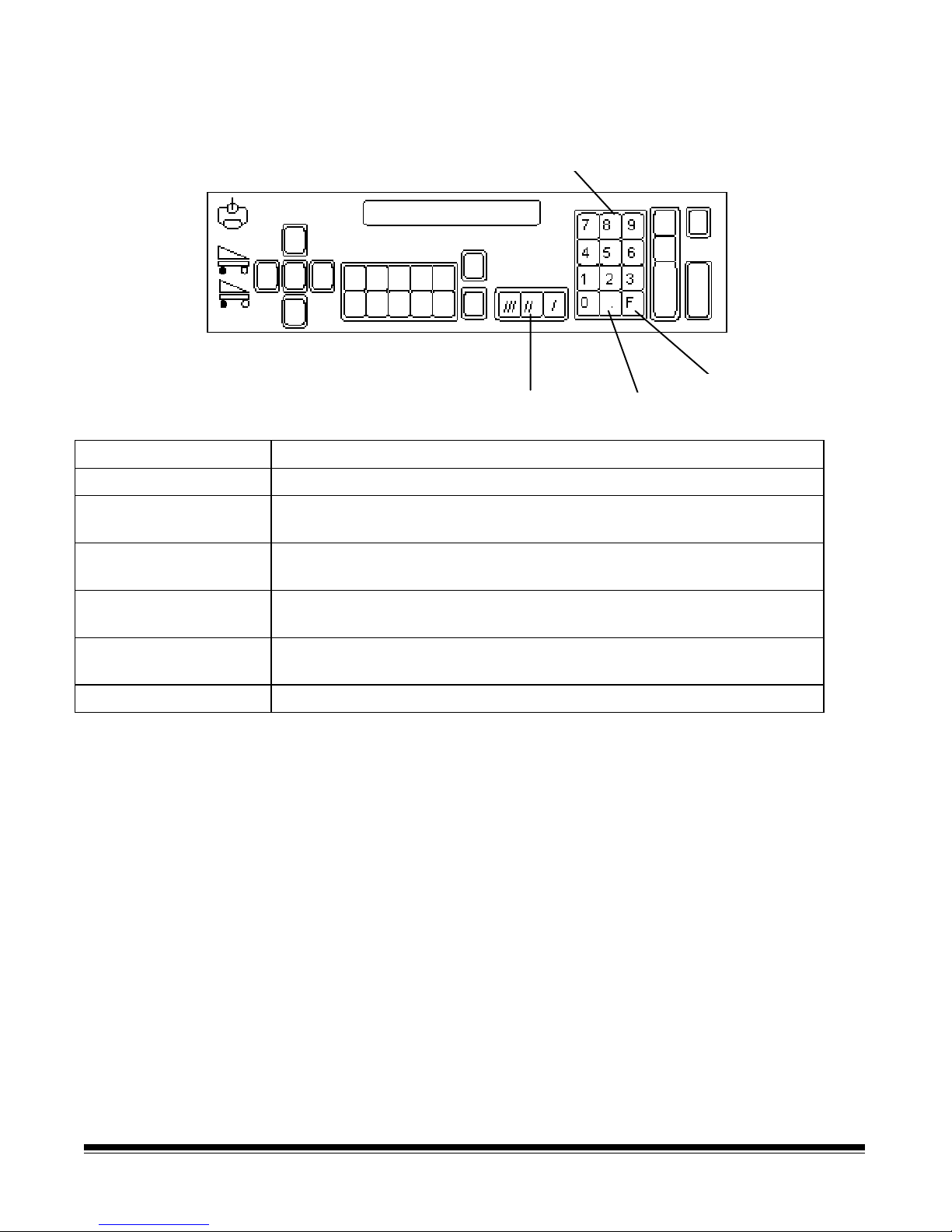
Operating keys and indicators
Numeric keys
Fkey
Level keys Decimal key
Keys/Indicators Function
Numeric keys (0-9) Enter numeric data such as an image address or function code.
F key Selects one of the available functions, when used with the numeric
keys.
Level 3 key Identifies the next document f ed into the scanner/microimager as a
level 3 document.
Level 2 key Identifies the next document f ed into the scanner/microimager as a
level 2 document.
Level 1 key Identifies the next document f ed into the scanner/microimager as a
level 1 document.
Decimal key Inserts a field separator in an image address.
1-8 A-61096 June 1999
Page 10
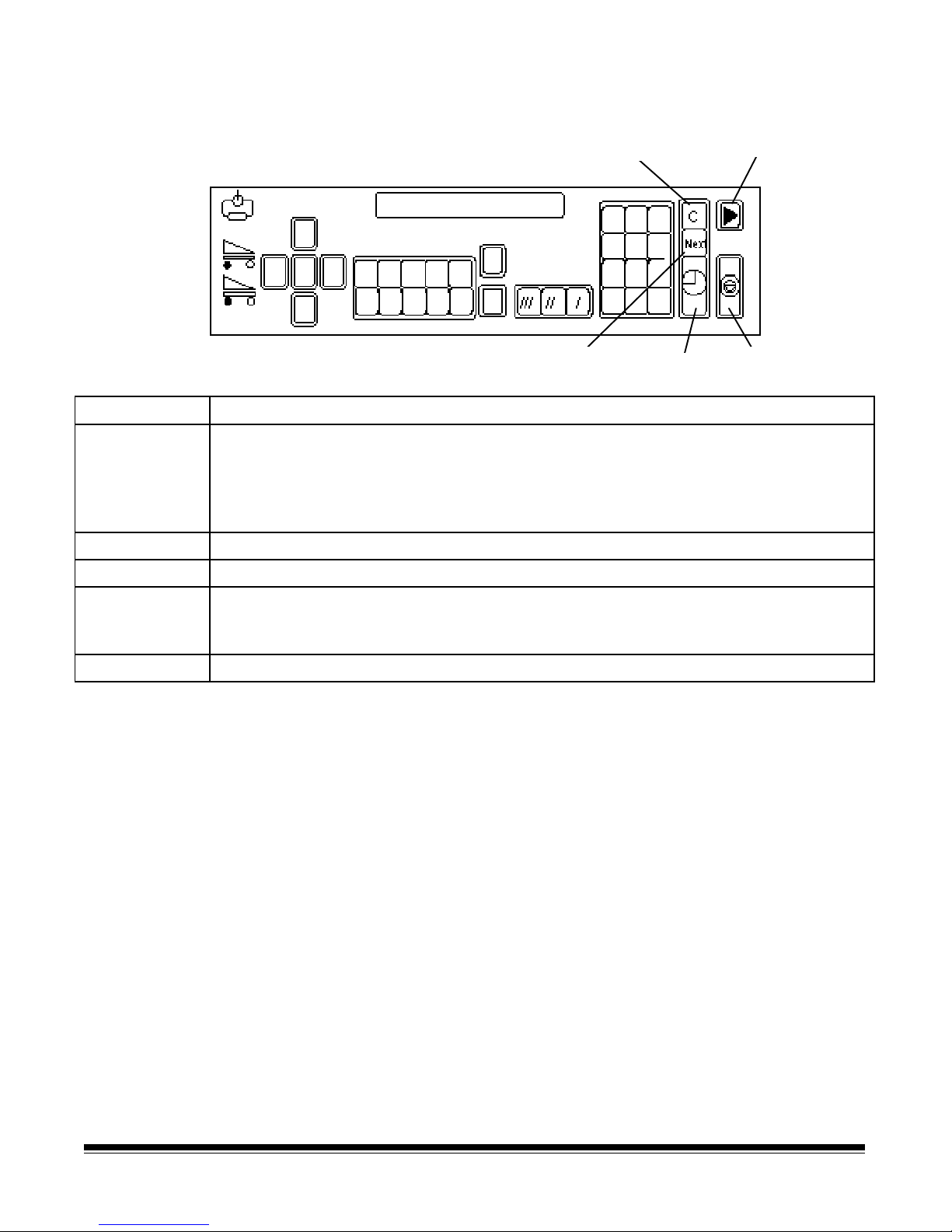
Operating keys and indicators
r
Clear/Cancel
Next
Key/Indicator Function
Clear/Cancel The C key allows you to:
• Cancel a function without changing the preset values.
• Clear the status display after executing specified function codes.
•
• Clear an operator message f rom the status display.
• •
Run Turns on the feeder and transport system.
NEXT Allows you to enter the next document image address.
Ente
Run
Stop
Stop Stops the feeder and transport system. Documents still in the transport system will
be scanned or microfilmed and placed in the exit hopper before the transport system
stops.
Enter Enters data for a f unction code or an image address change.
A-61096 June 1999 1-9
Page 11

2 Getting Started
The following steps are necessary to prepare the scanner/microimager
for operation. Procedures on how to perform these steps are described
in this chapter.
1. Turn on the main power switch.
2. Turn on the side panel switch.
3. Select the language display.
4. Load the f ilm into the cassette(s).
5. Load the cassette(s) into the scanner/microimager.
6. Change the lens holder position.
7. Select the mask.
8. Calibrate the scanner/microimager (if applicable).
9. Adjust the feed and separator roller gap.
10. Adjust the feed shelf position.
11. Adjust the feed shelf side guides.
Turning on the
scanner/microimager
12. Adjust the feed shelf side extension (if applicable).
13. Adjust the exit hopper side guides and end stop.
14. Change the deflector (if required).
15. Run an Exposure Step Test (if required).
16. Prepare the documents for filming/scanning.
Follow the steps below to turn the power on to the scanner/
microimager.
1. Turn on the main power switch (located at the rear of the machine).
NOTE: It is not necessary to turn off the main power switch during
normal daily operations.
2. Turn on the side panel switch.
Wait until the status d isplay indicators are lit and an operating display
appears before continuing.
40X
A-61096 June 1999 2-1
Page 12
Selecting the language
display
The scanner/microimager may have been configured at installation to
allow use of a second language in the status display. The language
used (French, German, Italian, Spanish, or other) is defined during
installation. If available, the alternate language display may be
accessed using function code F19.
Loading film into the
cassette(s)
IMPORTANT:
Always load and unload film in subdued indirect light to
help prevent “fogging”.
The following steps are required to load film into the cassette(s):
1. Select the correct film for your application(s)and appropriate
cassette(s).
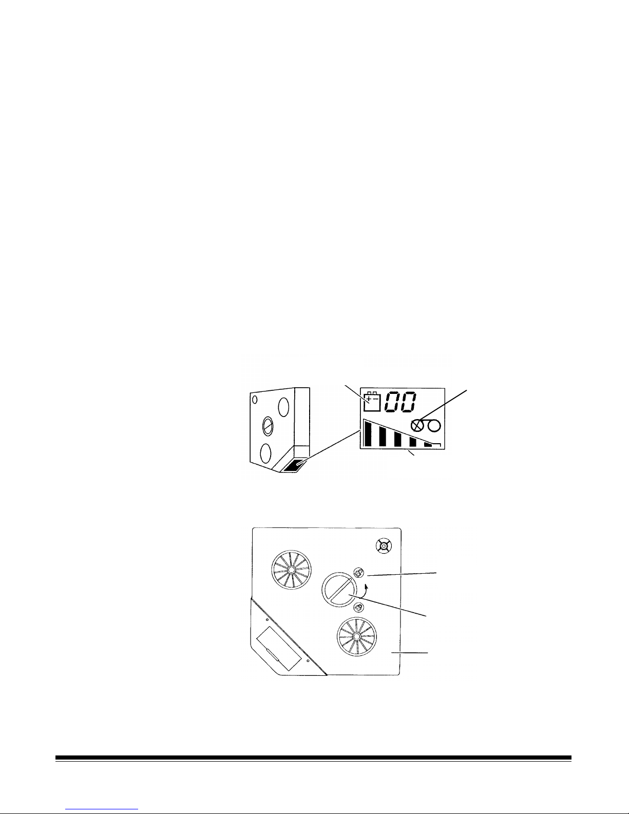
2. Check the cassette display bef ore loading a new roll of film. Verify
that:
• The film supply indicator shows the cassette is empty.
•
• There is not a low battery symbol. If a low battery symbol
• •
appears, or the display is not visible, replace the battery (refer
to Chapter 5,
Maintenance
, “Replacing the film cassette
battery”).
Low battery symbol
appears here
Cassette display
Empty film
supply indicator
Film supply i ndicator
3. Place the cassette on a flat surface, with the top cover side up (as
shown).
Unlocked
symbol
Cover latch
Top cover
4. Press down on the cover latch and turn counterclockwise to unlock
the top cover.
2-2 A-61096 June 1999
Page 13
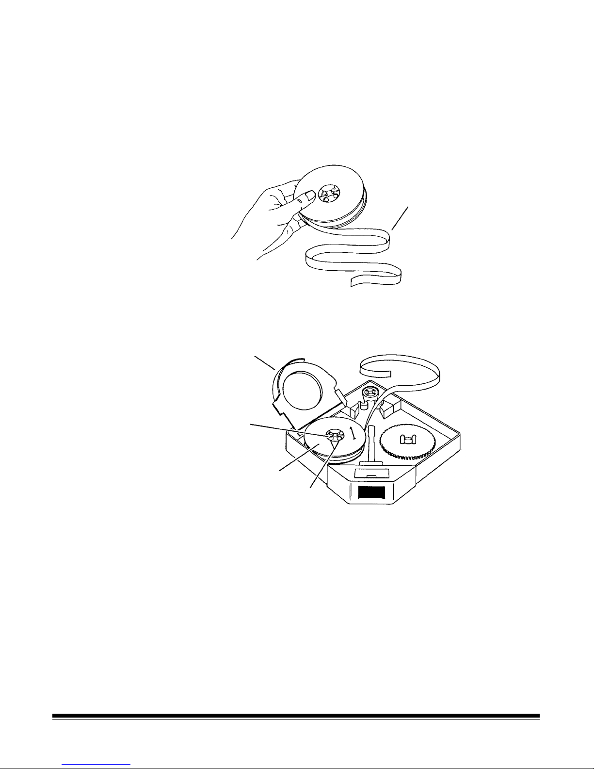
5. Remove the top cover and set it aside.
6. Open a new box of microfilm and remove the spool of film.
NOTE: Save the empty box to store the exposed film prior to
processing and f or storing the f ilm following processing.
7. Peeloff the paper band from around the spool.
8. Unwind approximately 18 in. (46 cm) of film.
18 in. (46 cm)
9. Lift the light guard and place the spool of film on the supply
spindle, with the number 1 side up.
Light guard
Lug
New spool
of film
Holes
10. Slowly rotate the spool until the two round holes on the spool
engage the lugs on the spindle.
11. Lower the light guard.
A-61096 June 1999 2-3
Page 14
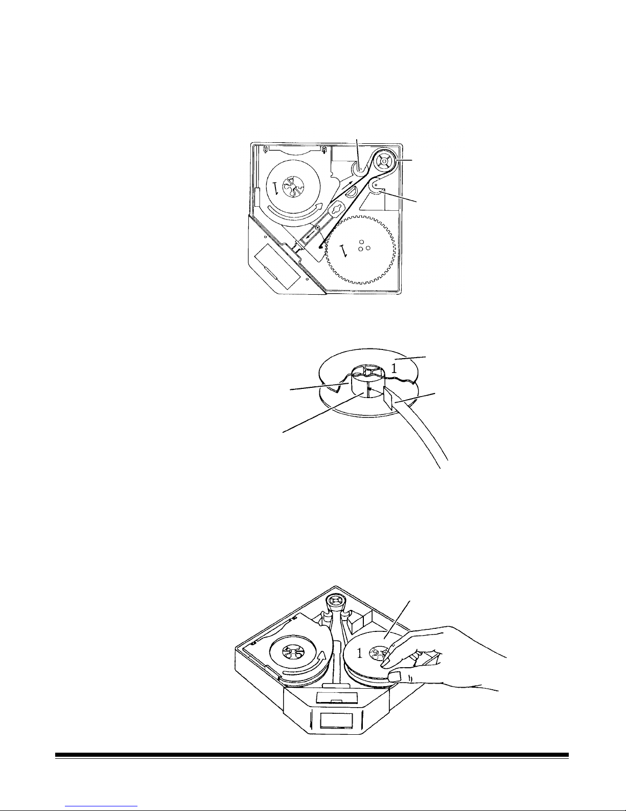
12. Thread the film around the guide roller, drive roller and idler roller,
following the path indicated by the threading arrows inside the film
cassette.
Guideroller
Drive
roller
Idler
roller
13. Fold back approximately ½ in. (1 cm) at the end of the film.
Take-up spool
Spool core
Slot
Fold film back
½-inch (1 cm)
14. Pick up the take-up spool and hold it with the number 1 side up.
15. Insert the folded end of the film into the slot in the take-up spool
core.
16. Rotate the spool counterclockwise to secure the film on the spool.
17. Place the take-up spool over the take-up spindle lugs.
Take-up spool
2-4 A-61096 June 1999
Page 15
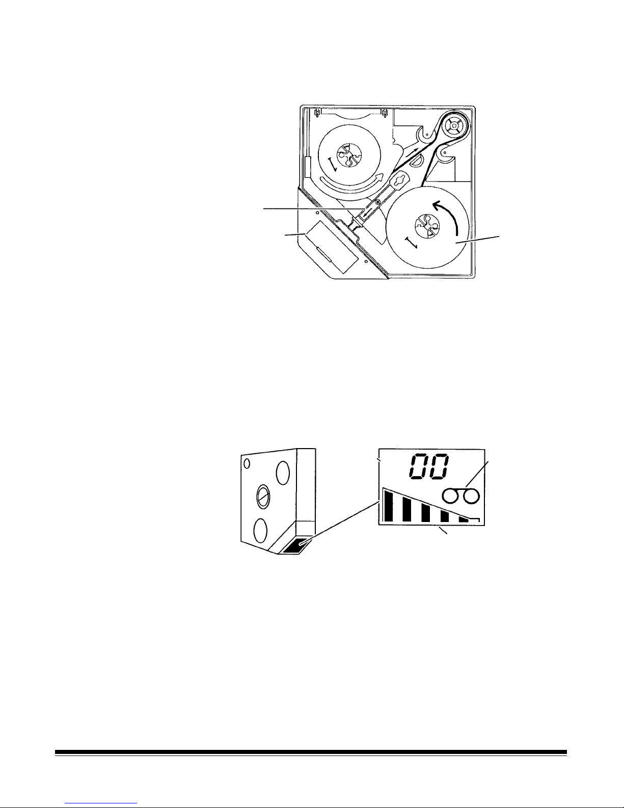
18. Slide the release lever toward the battery compartment and hold it
g
in this position.
Release
lever
Battery
compartment
Take-up
spool
19. Slowly rotate the take-up spool counterclockwise 3 complete turns
to secure the film onto the spool. Allow the release lever to return
to its normal position.
20. Replace the top cover on the cassette. Press down on the cover
latch and turn it clockwise to lock the top cover in place.
NOTE: If the film has been loaded correctly, the film supply
indicator changes to show the cassette is full.
Cassette display
Film spool
loaded
A-61096 June 1999 2-5
Full roll of film / cassette not inserted
into scanner/microima
er
Page 16
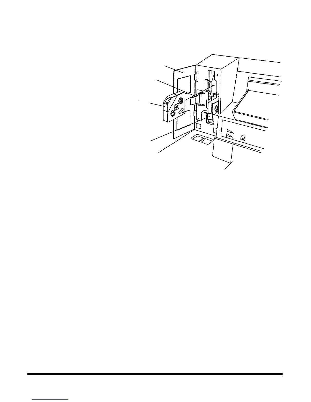
Loading cassette(s) into
r
the scanner/microimager
A film cassette may be loaded into either the upper or lower film slot.
Cassette
access doo
Drive release
lever
Upper cassette
Lower cassette
(in place)
1. Open the cassette access door.
2. Swing the drive release level (green handle) out.
3. Insert the film ca ssette(s).
NOTE: Refer to the label on the inside of the cassette access door
for cassette orientation. The display on the film cassette is
oriented dif f erently depending upon the film slot being
used.
4. Swing the drive release lever back into place.
5. Close the cassette access door.
Whenever a new or partial roll of film is loaded into the scanner/
microimager, a leader is automatically made when the cassette access
door is closed and the side panel switch is turned on.
A
Please Wait…
message appears in the status display while the film
leader is advanced. Once a normal operating display appears,
indicating the leader has been advanced, check the film supply
indicators on the control panel to verify that a f ull roll of film is
indicated.
2-6 A-61096 June 1999
Page 17
Entering a cassette ID
r
number
The cassette ID number that appears in the cassette display may be
entered or changed using function code F36.
Cassette ID numbe
Selecting the lens
reduction
A lens reduction must be selected so the filmed images are exposed
correctly on the film.
The lens reduction selected is based on the film mode used and the
width of the documents to be filmed:
Maximum Document Width using
Lens Reduction
Film Mode 24X 40X 50X
Simplex
Duplex
Duo
12 in
30 cm
not allowed 10.2 in
not allowed 8.9 in
10.2 in
25.5 cm
25.5 cm
22.25 cm
12 in
30 cm
12 in
30 cm
10.2 in
25.5 cm
A-61096 June 1999 2-7
Page 18
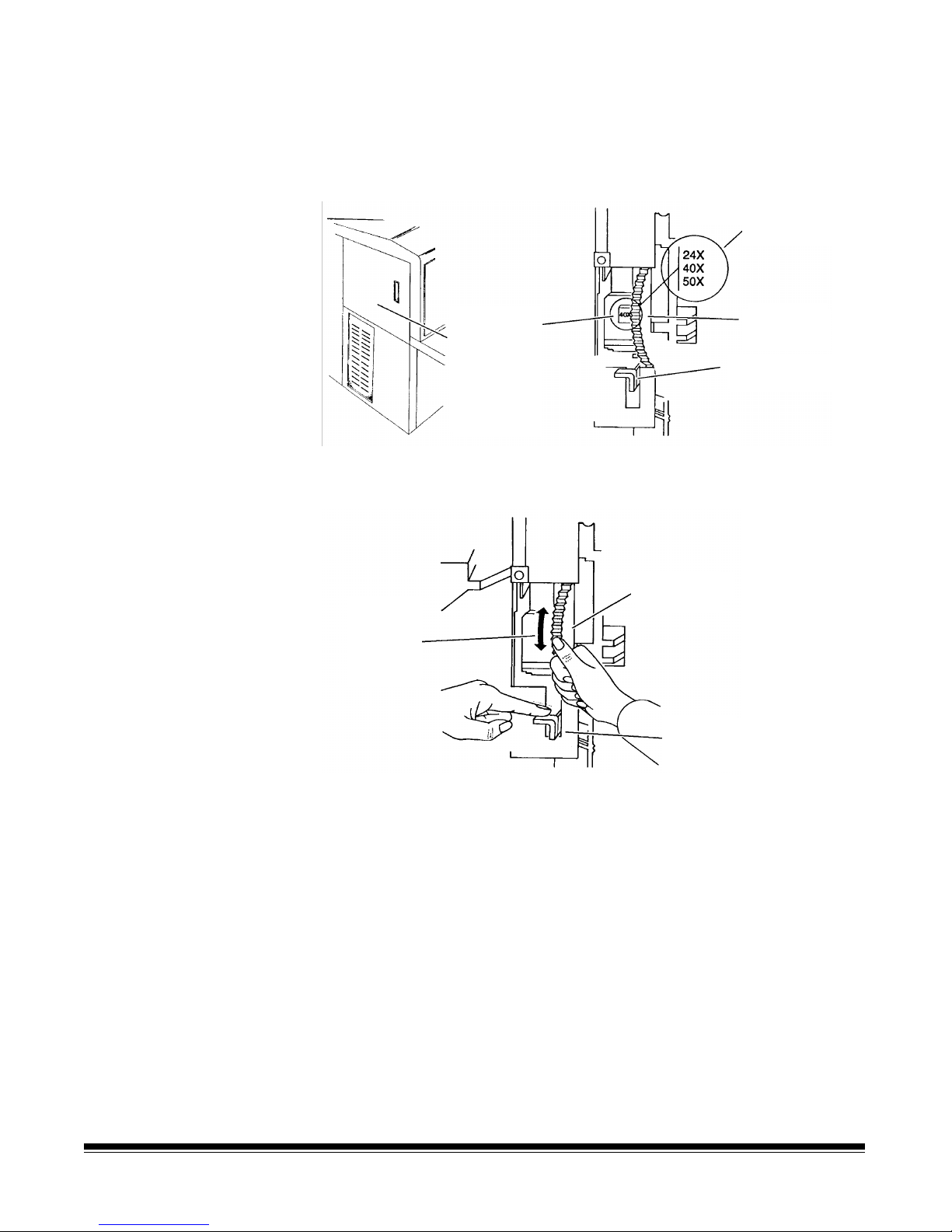
Changing the lens holder
position
Once the proper lens reduction has been selected, change the lens
holder position to reflect the desired lens reduction.
1. Open the left-side access door.
Available lens
reductions
Current lens
reduction
(inside leftside access
door
Press to unlock
2. Press down and hold the lens holder lock as shown.
Lens holder
Lens
reduction
label
location
Lens
holder lock
Lens holder
2-8 A-61096 June 1999
3. Rotate the lens holder up or down until the lens reduction selected
is displayed facing you.
4. Release the lens holder lock. Releasing the lock causes a groove
in the lens holder to be engaged, ensuring that it does not rotate
freely.
5. Close the left-side access door.
NOTE: A double-asterisk (**) appears in the first line of the status
display if the lens holder position is not set properly (i.e., if
the lens holder is positioned between lens reductions).
Page 19
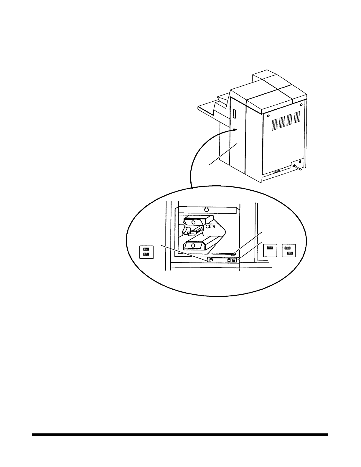
Selecting the mask
r
Select the film mask that corresponds to the film mode used.
1. Open the right-side access door.
Right-side
access door
Film mask leve
Duplex setting
Simplex or Duo
2. Slide the film mask lever to the left when using the duplex film
mode, or to the right when using the simplex or duo film mode.
3. Close the right-side access door.
A-61096 June 1999 2-9
Page 20

Calibrating the
scanner/microimager
NOTE: Disregard this section if the current mode configuration is
filming only.
Calibration sets the intensity of the lamps, which contributes to the
overall quality of the scanned document image.
The scanner/microimager should be calibrated:
• At least once a day when the scanner/microimager is turned on
using the side panel switch — prior to scanning documents.
• Any time the scanner/microimager is turned on using the main
power switch.
• If image quality is poor.
• After changing a Document Scanning Array lamp.
Calibrate the scanner/microimager using a calibration target (sheet of
paper) that is:
• Blank
• Clean
• Matte finish (not glossy)
• White or the same color as the background color of the documents
to be scanned. If you are scanning a variety of colored documents,
use a white calibration target.
• Wider than the documents you are going to scan (i.e., to scan
8 1/2 x 11 inch (215.9 x 279.4 mm) documents, the calibration
target should be wider than 8 1/2 inches (215.9 mm). The
recommended width for the calibration target is 12 inches (300
mm).
2-10 A-61096 June 1999
Page 21
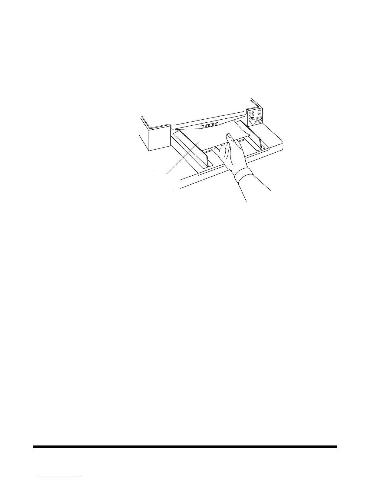
To calibrate the scanner/microimager:
1. Verify the main power and side panel switches are on. A normal
operating status display should appear.
2. Press P5 or enter function code F37 to start the calibration
sequence.
3. Insert the calibration target into the feeder.
Calibration
target
NOTE:When using a Document Scanner/Microimager 990S, you
are prompted to enter the calibration target once. When
using a Document Scanner/Microimager 990D, you are
prompted to enter the calibration target twice.
Unsuccessful calibration
When calibration is successful, the status display returns to a normal
operating display.
If calibration is not successful, a message appears in the status
display.
You may need to:
• Verify you are using a clean, blank sheet of paper as a calibration
target.
• Verify there is not a document already in the document path. (Refer
to the section entitled, “Clearing the document path” in Chapter 7.)
• Clean the Document Scanning Array. (Refer to the section entitled,
“Cleaning the Document Scanning Array” in Chapter 5.)
• Calibrate the scanner/microimager again. If calibration fails again,
change the lamps. (Refer to the section entitled, “Replacing the
exposure lamps” in Chapter 5.)
If you have done all of the above and calibration still fails, contact your
service representative.
A-61096 June 1999 2-11
Page 22

Adjusting t he feed and
separator roller gap
IMPORTANT:
Before adjusting the feed and separator roller gap, be
sure the feed and separator rollers are clean. Cleaning
the feed and separator rollers will frequently resolve
document feeding problems.
The adjustment procedure should only be done when
feeding and separating problems continue after the
feed and separator rollers have been cleaned . For
procedures on cleaning rollers, see Chapter 5,
Maintenance.
The gap adjustment knob on the control panel increases or decreases
the space between the feed and separator rollers. The gap must be
adjusted properly for smooth transportation of documents without
document overlap.
When documents of different thicknesses are fed in a group, adjust the
gap using the thinnest document in the group.
The feed and separator roller gap may have to be adjusted to
compensate for:
• Very thin documents (onion skin, tracing paper, etc.).
• Very thick documents (card stock, punch cards, cover stock).
• Some coated documents (photographic paper, plastic-coated
paper).
If the gap is not adjusted properly:
• More than one document at a time may be drawn into the transport
system at the same time; not all of the documents will be
scanned/filmed.
• Documents may be drawn into the transport too quickly; documents
may overlap or be spaced too closely (causing an error display).
• Documents may become skewed during transport; jamming may
occur.
NOTE:Priorto performing the adjustment procedure, the
scanner/microimager must be calibrated and enabled.
To adjust the feed and separator roller gap:
1. Turn on the side panel switch.
2. Enterfunction code F04 and enable counting-only.
3. Press Enter.
4. Press Run.
IMPORTANT:
Do not make a gap adjustment w hile documents are in
the feeder or transport system; doing so will produce an
inaccurate adjustment
.
2-12 A-61096 June 1999
5. Turn the gap adjustment knob clockwise three complete turns, or
until it stops, to open the gap between the feed and separator
rollers.
Page 23
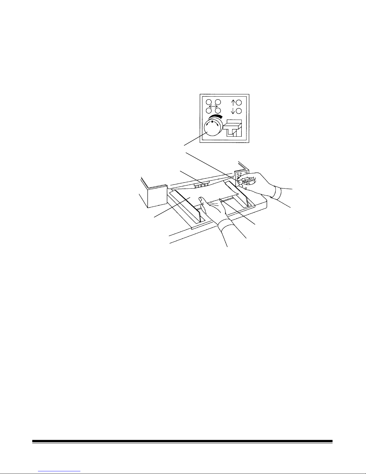
6. Turn the gap adjustment knob counterclockwise 2 1/2 turns.
7. Select two documents of the same size, texture and thickness,
similar to the types of documents you will be processing.
8. Place one document on top of the other. Hold the documents firmly
by their trailing edges. Insert them into the gap approximately 1/8
in. (3 mm).
Gap adjustment knob
Feed rollers
Separated
document
Trailing edge of top
document
If the documents separate, repeat the following steps until the
documents do not separate:
• Turn the gap adjustment knob clockwise 1/2 turn.
• Insert the documents again.
If the documents do not separate, proceed with Step 9.
9. Rotate the gap adjustment knob counterclockwise 1 or 2 clicks.
10. Hold the trailing edges of the documents firmly. Insert them into
the gap.
• If the bottom document is not separating from the top
document, remove the documents and repeat Steps 9 and 10
until the bottom document separates from the top document by
approximately 1 in. (25.4 mm).
• If the bottom document is separating from the top document,
proceed with Step 11.
A-61096 June 1999 2-13
Page 24
11. W hen you have adjusted the gap so the bottom document
separates consistently from the top document, rotate the gap
adjustment knob counterclockwise another 1 or 2 clicks to
complete the adjustment.
12. Feed a stack of 50 to 100 documents twice through the transport
system. Verify the final count reflects the total number of
documents that were fed and that the counter shows the same
amount each time the documents are counted.
If the count is not the same, the gap is not adjusted correctly.
Rotate the gap adjustment knob counterclockwise another 1 or 2
clicks and repeat Step 12. Repeat until corrected.
13. Press Stop.
14. Enter function code F04 and disable Counting-only.
15. Press Enter.
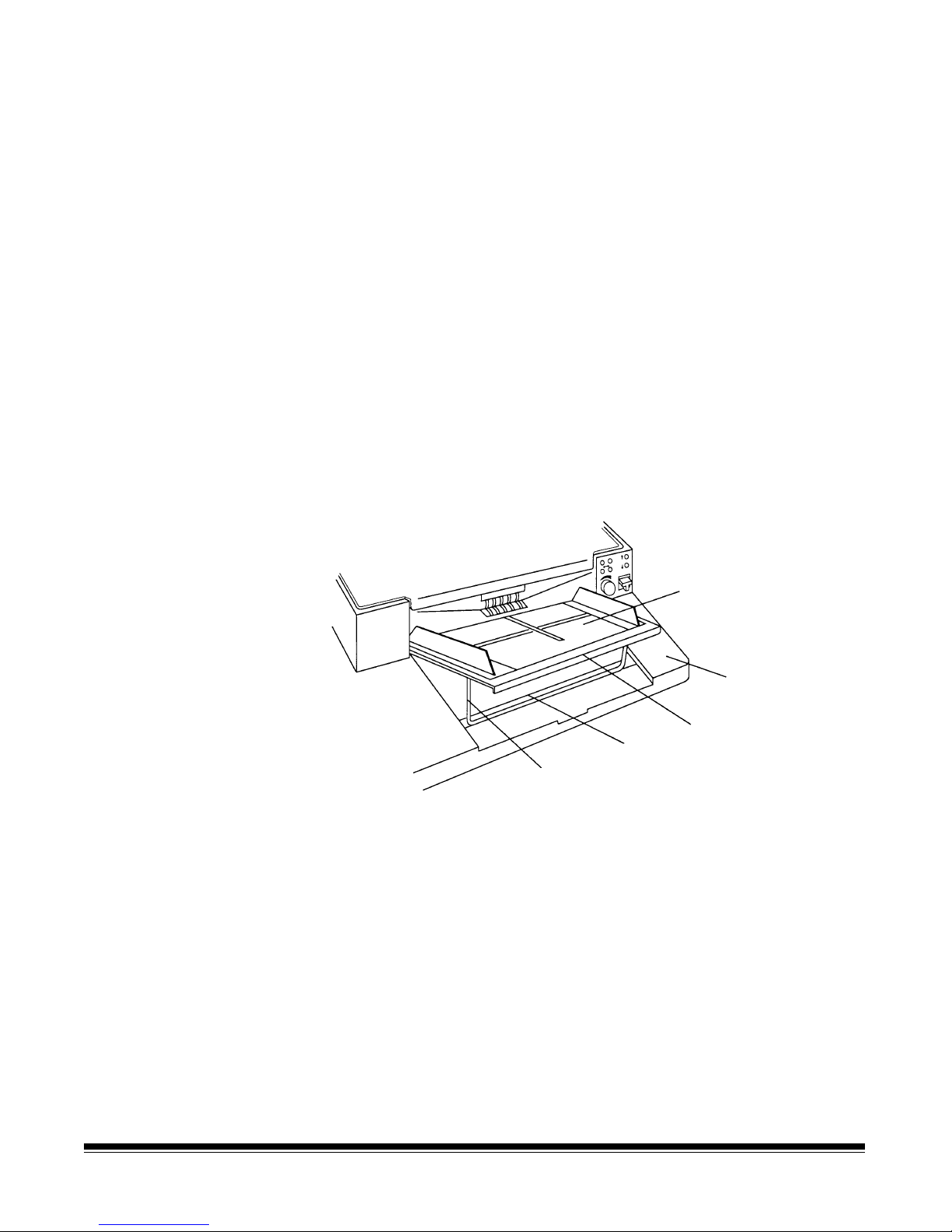
Adjusting t he feed shelf
position
Before you begin feeding documents into the scanner/microimager,
adjust the position of the feed shelf.
Feed shelf
Work shelf
Groove
Height
adjustment arm
Front edge of
feed shelf
To semi-automatically feed multiple documents, the feed shelf should
be in the raised position (as shown above).
To raise the feed shelf:
2-14 A-61096 June 1999
1. Grasp the front of the feed shelf and lift it up.
2. Swing the height adjustment arm out and insert it into the groove
on the work shelf.
To hand-feed documents (one at a time), the feed shelf should be in
the down position (not shown).
Page 25

To lower the feed shelf:
1. Grasp the front of the feed shelf and lift it up until the height
adjustment arm is no longer resting in the groove on the work shelf.
2. Push the height adjustment arm forward and gently lower the feed
shelf into position, level with the work shelf.
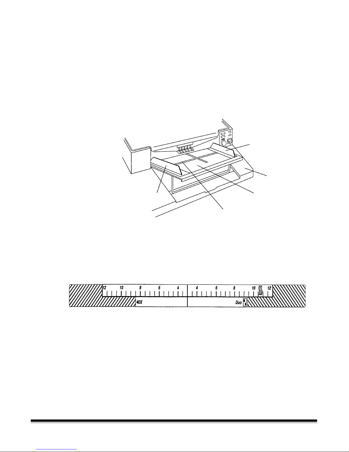
Adjusting t he feed shelf
length
NOTE: This section should be disregarded when using a
scanner/microimager 990S.
The feed shelf length may be adjusted to accommodate non-standard
size documents.
To adjust the feed shelf length:
• Grasp the front edge of the feed shelf and pull the feed shelf
extension toward you.
Feed shelf
Feed shelf
extension
Front edge of
feed shelf
To retract the feed shelf length:
• Push the feed shelf extension gently back into its original position.
A-61096 June 1999 2-15
Page 26
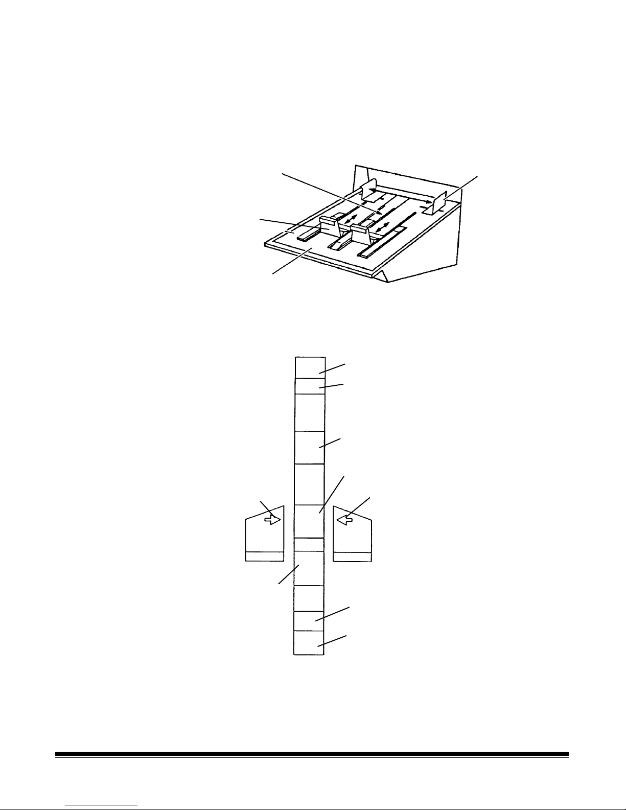
Adjusting t he feed shelf
side guides
Before you begin processing documents, adjust the side guides on the
feed shelf to accommodate the documents being processed.
If you are scanning and filming:
• Slide the feed shelf side guides apart, leaving approximately 1/16
in. (2 mm) clearance on each side of the documents. The
documents are automatically centered across the width of the
transport. You may adjust the side guides to feed documents offcenter by holding one of the side guides in place and then sliding
the second side guide into the desired position.
Side guide
Work shelf
Side guide
Feed shelf label
Front edge of
feed shelf
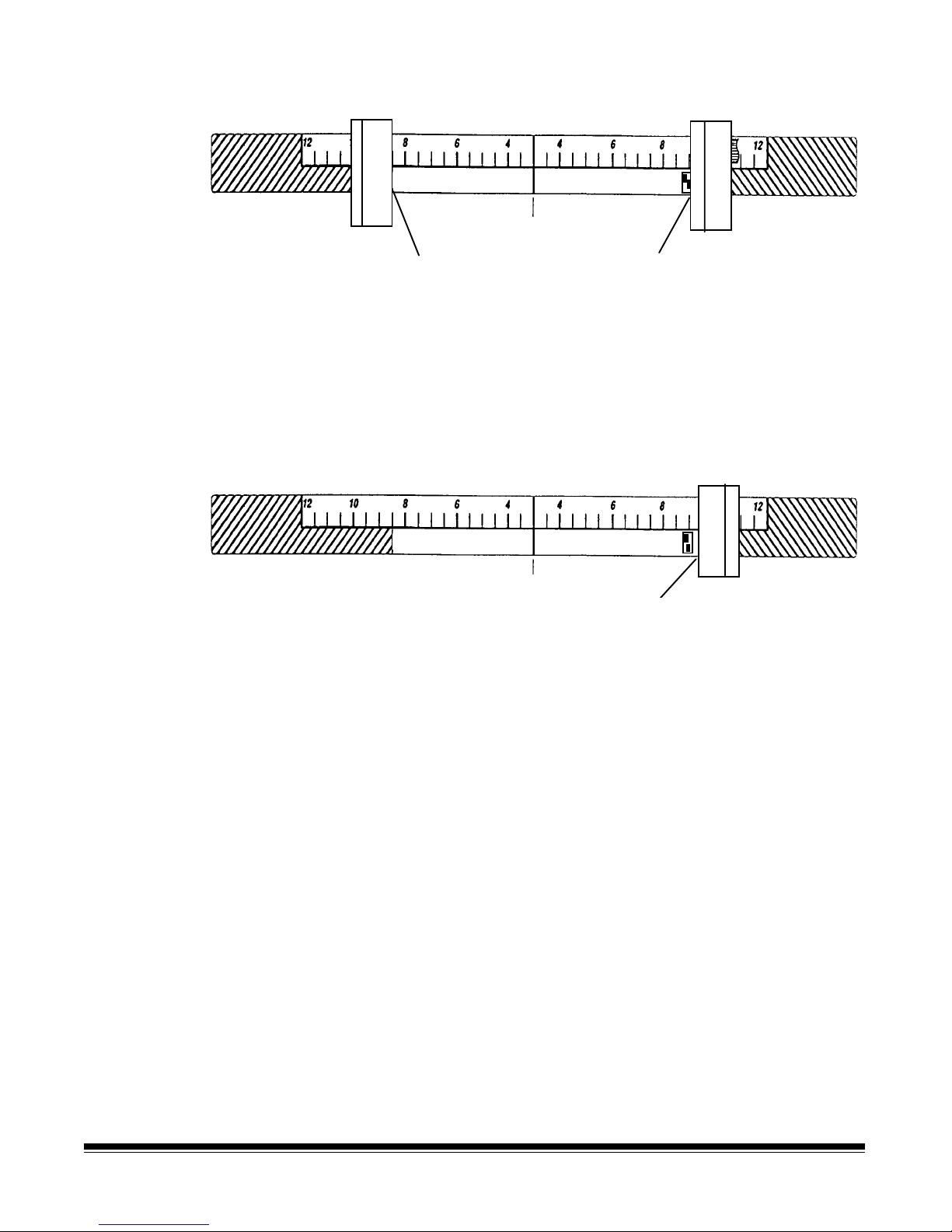
If you are filming only (no scan):
1. Determine the lens reduction and film mode you are using
(simplex, duplex, or duo).
2. Slide apart the side guides on the feed shelf until the feed shelf
label is visible.
3. Use the examples on the following page(s) to determine where to
set the side guides. Leave approximately 1/16 in. (2 mm) clearance
on each side of the documents so they feed properly.
IMPORTANT:
Microfilming documents which exceed the maximum
document size can result in loss of document
information on the microfilm.
2-16 A-61096 June 1999
If the documents are smaller than the area shown on the feed shelf
label, center the documents within the label boundaries on the feed
shelf. Readjust the side guides to fit the documents, allowing 1/16 in.
(2 mm) on either side of the document.
Page 27
If the documents are larger than the area shown on the feed shelf
label, and do not fit between the side guides, rotate and reposition the
documents within the side guides. If the documents still do not fit within
the label boundaries and extend past the side guides, you may have
selected an incorrect lens reduction and/or film mode for the size of
your documents. Refer to the section entitled, “Selecting a lens
reduction” earlier in this chapter. This section lists the maximum
document size allowed by each lens reduction and microfilming mode.
The following examples show the correct placement of the feed shelf
side guides for each possible combination of lens reduction and film
mode:
24X reduction ratio; simplex film mode
50X reduction ratio; simplex film mode
Center Line
Center the documents, allowing approximately 1/16 in. (2 mm)
clearance on each side of the documents so they feed properly.
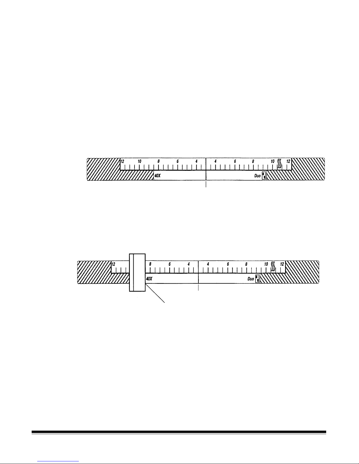
40X reduction ratio; simplex film mode
Center Line
Left feeder side guide should be aligned here
Set the left feed shelf guide side shelf where indicated.
Set the right feed shelf side guide dependent upon the width of the
document, allowing approximately 1/16 in. (2 mm) clearance on each
side of the documents so they feed properly.
A-61096 June 1999 2-17
Page 28

40X reduction ratio; duplex film mode
40X
Center Line
Left feed shelf side guide should be aligned here
Duo
Set the left feed shelf side guide where indicated. Set the right feed
shelf side guide dependent upon the width of the document, allowing
approximately 1/16 in. (2 mm) clearance on each side of the
documents so they feed properly.
50X reduction ratio; duplex film mode
Center Line
Center the documents, allowing approximately 1/16 in. (2 mm)
clearance on each side of the documents so they feed properly.
2-18 A-61096 June 1999
Page 29
40X reduction ratio; duo film mode
40X
Left feed shelf side guide should be aligned here
Set the left and right feed shelf side guides where indicated. Allow
approximately 1/16 in. (2 mm) clearance on each side of the
documents so they feed properly.
50X reduction ratio; duo film mode
40X
Duo
Center Line
Right feeder si de guide should be aligned here
Duo
Center Line
Right feed shelf side guide
should be aligned here
Set the right feed shelf side guide where indicated. Set the left f eed
shelf side guide dependent upon the width of the document, allowing
approximately 1/16 in. (2 mm) clearance on each side of the
documents so they feed properly.
A-61096 June 1999 2-19
Page 30
Adjusting the exit
)
hopper side guides and
end stop
The exit hopper side guides and end stop must be adjusted so
documents are stacked properly after processing.
1. Adjust the side guides on the exit hopper to match the adjustment
of the side guides on the feed shelf.
Exit hopper
label
End
stop
Exit hopper
Side guides
(arrows depict
correct placement
of side guides)
2. Adjust the end stop of the exit hopper by determining the longest
document to be processed. Slide the end stop until the arrows
point to where the length of the longest document is shown on the
exit hopper label.
Checks
IBM cards
5-inch
8½-inch(A5
ArrowArrow
11-inch (A4)
14-inch (B3)
17-inch with
adapter (A3)
2-20 A-61096 June 1999
Page 31

Changing the deflector
The scanner/microimager comes with two deflectors (stored in the
pocket located inside the right-side access door), designed to help
stack the documents as they exit the transport sy stem and enter the
exit hopper.
Use the short deflector for documents less than 5 in. (13 cm) and the
long deflector for documents longer than 5 in. (13 cm) as well as for
mixed sizes.
Short document deflector
Attachment
pins
Long document deflector
Holding clip
Deflector
Front cover
(does not have to
be open to attach
deflectors)
(Swings to right)
1. Grasp the deflector near the attachment pin (as shown).
Lip of exit hopper
Deflector
(black side must be down)
2. Guide the def lector into the exit hopper, just below the lip of the
hopper, to insert the attachment pin in the holding clip.
3. Pull the deflector toward you until it clicks into place.
A-61096 June 1999 2-21
Page 32

Running an exposure
step test
An Exposure Step Test is run to determine the proper AEC illumination
level.
Perform an Exposure Step Test whenever one (or more) of the
following conditions is true:
• After changing exposure lamps.
• Before using a diff erent type of microfilm.
• Before using a different microfilm processing lab.
• After a change in processing lab results are noticed.
Before running an Exposure Step Test, clean all mirrors and imaging
guides. Refer to Chapter 7,
Maintenance
.
The following procedure outlines how to generate a step test filmstrip.
After the test is completed, the film should be unloaded and
processed. It is recommended that no filming take place until the
results of the test are evaluated and the proper AEC illumination level
is determined.
1. Prepare 10 plain white forms numbering them from 0 through 9.
The numbers should be at least 1 in. (25 mm) high.
2. Insert two film cassettes, loaded with the same type of microfilm to
be used during normal operation.
NOTE: If you do not have two f ilm cassettes, insert a single film
cassette in the upper slot, run the Exposure Step Test,
change to the lower slot, and rerun the Exposure Step
Test.
3. Enterfunction code F24. Verify that the AEC is turned on. If it is not
on, press 1 and then Enter to turn it on.
4. Enterfunction code F25.
• Use the left arrow key to change the base illumination level to 0
(the lightest setting). Press Enter and then Run. Select the
plain white form with the number 0 printed on it. Feed the
document into the transport two or three times.
• Use the right arrow key to change the base illumination level to
the next highest setting. Press Enter and then Run. Select the
plain white f orm with the next highest number on it. Feed the
document into the transport two or three times.
• Repeat this process until all 10 forms have been f ilmed.
5. Press the C key.
6. Enterfunction code F24.Press0 and then Enter to turn the AEC
off.
2-22 A-61096 June 1999
Page 33

7. Enterfunction code F26.
• Use the left arrow key to change the base illumination level to 0
(the lightest setting). Press Enter and then Run. Select the
plain white form with the number 0 printed on it. Feed the
document into the transport two or three times.
• Use the right arrow key to change the base illumination level to
the next highest setting. Press Enter and then press Run.
Select the plain white form with the next highest number on it.
Feed the document into the transport two or three times.
• Repeat this process until all 10 forms have been filmed.
8. Press the C key.
9. Enterfunction code F27 to advance the film 2 to 3 f eet.
NOTE: It is recommended that you create a 6-foot leader by
entering function code F28. The advanced film protects the
images f rom exposure to roomlight.
10. Remove the film from the cassettes using the steps outlined in
Chapter 3,
Operating the Scanner/microimager.
11. Place each filmstrip in separate boxes and label each box with the
following information:
Preparing documents for
scanning
• Exposure Step Test
• Date of Test
• Upper or lower cassette used
• Type of microfilm used
• Machine used f or test (if more than one machine is on-site)
12. Send the f ilm for processing. For consistency, use the same
processing lab that processes your regular production work.
13. W hen the film is returned, evaluate it to determine which settings
produced the best images. Use a microfilmreader for the initial
evaluation; in addition, view the images via a reader/printer, or
however the end user see it.
Before you begin processing documents, be sure the documents will
feed through the scanner/microimager easily:
• Remove any staples, rubber bands, loose mending tape, or paper
clips from the documents to be processed.
• Straighten wrinkled edges and tape any torn documents.
• Trim ragged edges.
When using the automatic feeder, make certain all documents are of
similar size, texture, thickness and weight; and that the leading edges
of all documents are aligned.
A-61096 June 1999 2-23
Page 34

Document orientation
Documents appear on film in the same order and orientation in which
they are fed into the scanner/microimager. It is important to place the
documents in the desired order and orientation before feeding them
into the transport.
The documents may be either Cine or Comic orientation.
Cine Comic
2-24 A-61096 June 1999
Page 35

3 Operating the Scanner/Microimager
Overview
The scanning process consists of the following steps:
1. Prepare the scanner/microimager for operation (refer to Chapter 2,
Getting Started
2. Enable the scanner/microimager from the host system.
3. Select a mode for the application. Typically the host computer
performs this step, but it may also be performed by the operator.
4. Select temporary operating values (if required).
5. Check the film supply to verify there is enough film to complete the
job or batch.
6. Press Run.
7. Feed the documents into the transport.
• The scanner/microimager assigns a sequential ID number (for
digital image storage), the document image level and image
address.
• The document is scanned.
• The document is recorded on f ilm, along with the appropriate
image mark.
for more information).
• The document image header is created.
• The host computer initiates transfer of the document image
header and document image to the host system for storage on
magnetic or optical disk media.
• Documents are deposited in the exit hopper, face down, in the
order in which they were fed into the transport.
8. Press Stop.
9. Enterfunction code F38 to indicate end-of-job.
10. Unload the film cassette(s).
11. Turn off the side panel switch.
NOTE: If the scanner/microimager will not be used for 8 hours or
more, turn of f the main power switch.
A-61096 June 1999 3-1
Page 36

Selecting a mode
The scanner/microimager offers 18 modes that may be programmed
for a particular application or group of applications.
The modes are programmed at the time of installation and stored for
easy access and use.
Typically, the mode is selected via the host system, using a scannerunique command. However, you may manually select a mode.
To select a mode, either:
• Enter function code F01 (Select Mode) or F91 (Select Linked
Mode).
or
• Check with yo ur system administrator to see if one or more of the P
keys has been preprogrammed to perform specific functions.
Temporary operating
values
Each of the 18 modes programmed at the time of installation contain
definitions that affect the output of the scanner/microimager. Each
mode is programmed to conform to the output requirements of a
particular application or group of applications.
There may be instances, however, when a particular application
requires some variation of an existing mode. In such instances, mode
definitions may be changed using available function codes. See
Chapter 4,
function codes.
NOTE: Changes to mode def initions remain in effect until another
Example:
If Mode 15 contains definitions that allow you to use the
Imagelink
from the leading edge of the document the endorsement is printed) is
programmed to be ½-inch.
Function Codes,
mode is selected or the side panel switch is turned off . The
original mode definition is only affected by these changes if
the mode overrides are saved (the mode override option may
be selected at installation and if selected, a plus sign (+)
appears in the first line of the status display).
for a listing and description of the available
Kodak
Endorser, the starting print position (which defines how f ar
3-2 A-61096 June 1999
If there is a special application that requires the endorsement be
printed 1 inch from the leading edge of the document, you may use
function code F59 to temporarily change the starting print position.
Page 37

Setting the automatic
exposure control
Automatic Exposure Control (AEC) provides optimal film quality by
helping to ensure that filmed documents are exposed at the proper
level.
Before filming documents, determine whether the AEC should be
turned on or off.
When AEC is turned on, it automatically adjusts for variations in
contrast, color, etc. Typically, AEC is turned on for average or normal
documents.
When AEC is turned off, it is fixed at a particular level f or documents
which have large areas of dense shading, etc.). Typically AEC is
turned off f or filming special documents such as transparencies, onion
skin documents or highly reflective documents.
NOTE: It is assumed that an Exposure Step Test has been
performed to determine the proper illumination level. Refer to
Chapter 2
To verify the mode selected specifies that AEC is on:
• Enter function code F24 (AEC On/Off).
The display shows: Automatic Exposure Control OFF (or ON)
− If the AEC is OFF, enter 1 to turn it on.
− If the AEC is ON, p ress the C key.
• Enter function code F25 (AEC Auto Adjust) to adjust the base
illumination level.
, Getting Started
for more information.
− Use the arrow keys to lighten or darken the base illumination
level (where 0 is the lightest and 9 is the darkest).
− Press Enter when the level has been adjusted correctly.
To verify the mode selected specifies that AEC is off:
• Enter function code F24 (AEC On/Off).
The display shows: Automatic Exposure Control OFF (or ON)
− If the AEC is ON, enter 0 to turn it off.
− If the AEC is OFF, press the C key.
• Enter function code F26 (AEC Fixed Adjust) to adjust the fixed
illumination level.
− Use the arrow keys to lighten or darken the fixed illumination
level (where 0 is the lightest and 9 is the darkest).
− Press Enter when the level has been adjusted correctly.
A-61096 June 1999 3-3
Page 38

Checking the film
r
supply
The film supply indicators, located on the left side of the control panel,
are used to determine whether or not there is enough film to complete
the job. The indicator has 10 vertical bars, each representing 10% of a
full roll of film (i.e., if all 10 bars are displayed, a full roll of film is
available; if 8 bars are displayed 80% of the roll is available, and so
on). A warning message appears when the film supply is down to
10%.
Upper cassette indicator
10%
Lower cassette indicato
10%
NOTE: You can also enter f unction code F30 to determine how much
film remains. The amount of film remaining in both the upper
and lower cassettes is displayed. In addition, the approximate
number of documents which can be filmed on the remainder
of the roll(s) is displayed.
3-4 A-61096 June 1999
Page 39

Feeding documents
After the scanner/microimager has been prepared for operation, and
the desired mode and any temporary operating values have been
defined, you are ready to feed documents into the transport.
1. Verify the side panel switch is on and all proper adjustments have
been made (feeder side guides, exit hopper side guides, etc.).
2. Press Run.
3. Select a stack of documents that is no more than a ½-inch (1 cm)
thick.
4. Fan the stack of documents so the leading edge of the top
document engages the feed/separator rollers as shown:
5. Place the stack of f anned documents into the feeder so the leading
edge of the top document contacts the feed/separator rollers. The
documents are drawn into the transport, with the top document
being fed first. The documents are deposited in the exit hopper
face down, in the order in which they were fed into the transport.
6. Repeat Steps 3 through 5 until all of the application documents
have been fed into the transport.
7. Press Stop after all documents have been deposited in the exit
hopper.
NOTE: When using simplex or duplex mode, the f ully or partially
exposed roll(s) of f ilm can be unloaded when the
application is completed. When using duo mode, refer to
the section “Using duo mode” later in this chapter.
A-61096 June 1999 3-5
Page 40

Feeding thick
documents
The gap release lever is used to feed thick documents such as card
stock or cover stock. The lever is located on the front panel of the
scanner/microimager, next to the gap adjustment knob.
Gap adjustment knob Gap release lever
1. Press down and hold the gap release lever. This opens the gap
between the feed and separator rollers, allowing thick documents
to pass between them. You will be able to see the gap open as the
lever is pushed down.
2. Insert the document past the rollers until it is taken into the
transport.
NOTE: If more than one thick document is to be scanned/filmed,
feed them into the transport one at a time.
Gap release l ever
(hold down)
3. After the thick document(s) have been scanned/filmed, release the
gap release lever. It will return to its original position. The feed and
separator rollers will return to the previously adjusted positions.
3-6 A-61096 June 1999
Page 41

Using duo mode
Duo mode allows you to double the number of single-sided documents
exposed on a single roll of film. This is done by rotating the cassette(s)
after the first side of the film has been fully exposed. Documents are
first exposed down one side of the film (channel A), until the end of the
roll is reached. Then, the cassette(s) are rotated and documents are
exposed down the other side of the film (channel B).
Due to the way in which documents are exposed when using duo
mode, the following recommendations are made:
• Do not mix duo mode microfilming with simplex or duplex mode
microfilming using the same roll of film.
• Do not unload a partially exposed roll of film created using duo
mode.
The following steps illustrate the use of duo mode:
1. Feed documents into the transport as described in the section
entitled, “Feeding documents”.
2. A message appears in the status display when the first side of the
film has been fully exposed:
E212 End of side 1, flip cassette
.
3. Open the cassette access door.
4. Swing the drive release lever (green handle) out.
5. Remove the cassette from the upper f ilm slot.
6. Rotate the cassette so the side two symbol (
) faces the control
panel (as shown). Refer to the labels inside the cassette access
door for proper orientation.
Cassette access door
Side two
symbol
Drive release
lever
Control panel
7. Reinsert the cassette into the upper film slot.
8. Repeat Steps 5 through 7 for the cassette in the lower f ilm slot.
A-61096 June 1999 3-7
9. Continue feeding documents. A message appears in the status
display when the second side of the f ilm has been exposed. Refer
to the section “Unloading a fully exposed roll of film” later in this
chapter.
Page 42

Unloading film
cassette(s)
You may unload a fully or partially exposed roll of film.
IMPORTANT:
Always load and unload film in subdued, indirect light
to help prevent "fogging.”
Unloading a fully
exposed roll of film
Use the following steps to unload a fully exposed roll of film (simplex,
duplex, or duo format).
It is assumed that all documents have been deposited in the exit
hopper and Stop has been pressed.
1. Perform function code F29 (Advance Film to End of Roll).
2. Open the cassette access door.
3. Swing the drive release lever (green handle) out.
4. Remove the film cassette(s).
5. Place the cassette on a flat surface, with the top cover side up.
6. Press down on the cover latch and turn it counterclockwise to
unlock the cover.
7. Remove the top cover and set it aside.
8. Place a finger over the take-up spool flange to prevent the film
from unwinding and lift up to remove the spool of f ilm.
9. Place the spool into the film box. Allow approximately 2 to 3 in.
(5 to 8 cm) of the film to protrude from under the lid of the box (as
shown). Close the top of the box securely.
2to3inches
(5to8cm)
10. W rite identification data (i.e., subject, title, date, job number, etc.)
on the film box label. The film is now ready for processing.
NOTE: Replace the top cover back on the cassette(s), regardless
of whether or not you immediately reload the cassette.
This helps to extend battery life.
3-8 A-61096 June 1999
Page 43

Unloading a partially
exposed roll of film
Follow the steps below to unload a partially exposed roll of film
(simplex or duplex format).
IMPORTANT:
Do not unload a partially exposed roll of film when using
duo mode. Images will be lost if a partial roll is
unloaded.
It is assumed that all documents have been deposited in the exit
hopper and Stop has been pressed.
1. Enterfunction code F28 (Film Advance).
2. Open the cassette access door.
3. Swing the drive release lever (green handle) out.
4. Remove the film cassette(s).
5. Place the cassette on a flat surface, with the top cover side up.
6. Press down on the cover latch and turn it counterclockwise to
unlock the cover.
7. Remove the top cover and set it aside.
Guideroller
Drive roller
Idlerroller
Release
lever
Battery compartment Take-up
spool
8. Slide the release lever toward the battery compartment and hold it
in this position.
A-61096 June 1999 3-9
Page 44

9. Place a finger over the take-up spool flange to prevent the film
10. Cut the film with a pair of scissors as indicated in the illustration
Supply spool
from unwinding.
(between the idler roller and the take-up spool).
Cut here
Take-up spool
flange
Place finger here
to prevent film from
unwinding
11. Lift the take-up spool out of the cassette.
12. Place the spool into the film box. Allow approximately 2 to 3 in.
(5 to 8 cm) of the film to protrude from under the lid of the box.
13. Close the top of the box securely.
14. W rite identification data (i.e., subject, title, date, job number, etc.)
on the film box label. The film is now ready for processing.
To continue filming using the unexposed portion of the roll of film:
1. Obtain an empty take-up spool.
2. Unwind approximately 18 in. (46 cm) of film.
3. Fold back approximately 1/2 in. (1 cm) at the end of the film.
4. Pick up the take-up spool and hold it with the Number 1 side up.
5. Insert the folded end of the f ilm into the slot in the take-up spool
core.
Take-up spool
Spool core
Fold film back
½-inch (1 cm)
3-10 A-61096 June 1999
Slot
Page 45

6. Rotate the spool counterclockwise to secure the film on the spool.
7. Place the take-up spool over the take-up spindle lugs.
8. Slide the release lever toward the battery compartment and hold it
in this position.
9. Slowly rotate the take-up spool counterclockwise 3 full turns to
secure the film on the spool. Allow the release lever to return to its
normal position.
Release
lever
Battery
compartment
Take-up
spool
10. Replace the top cover on the cassette. Press down on the cover
latch and turn it clockwise to lock the cover in place.
NOTE: The cassette may now be inserted into the
scanner/microimager and filming may continue.
A-61096 June 1999 3-11
Page 46

4 Function Codes
Using function
codes
There are a variety of functions available which may be used to
temporarily change operating conditions and values, and to obtain
system and accessory status information.
These functions are listed in the Function Code Summary later in this
chapter. Following are the procedures for using f unction codes:
1. Press the F key.
2. Press the numeric keys which correspond to the desired function
code.
3. Press Enter.
If the function is used to enable or disable an operation (turn an option
on or off):
1. Press 1 to turn the option On, or 0 to turn the option Off.
2. Press Enter.
If the function requires numeric input:
1. Press the numeric key(s) required.
2. Press Enter.
If the function is used to increment or decrement a measurement:
• Press the arrow keys to increment or decrement as follows:
− Press the Up arrow to increment the measurement by
1 inch (25 mm) or 1 value adjustment, or
− Press the Down arrow to decrement the measurement by
1 inch (25 mm) or 1 value adjustment, or
− Press the Right arrow to increment the measurement by
1/8-inch (3 mm), or
− Press the Left arrow to decrement the measurement by
1/8-inch (3 mm).
• Press Enter.
To cancel a function (before pressing Enter) or clear the status display
after executing a function code:
• Press C (Clear/Cancel).
A-61096 June 1999 4-1
Page 47

Function code
summary
Following is a summary of the functions and their corresponding
function code:
Status
Accessory Status*..............................................................F05
Date and Time Display* .....................................................F23
Elapsed Time*....................................................................F17
Counters
Level 0 Count* ...................................................................F10
Level 1 Count* ...................................................................F11
Level 2 Count* ...................................................................F12
Level 3 Count* ...................................................................F13
Total Document Count*......................................................F09
Reset Level Counts ............................................................F14
Setup
Action/Confirmation Tone ..................................................F93
Alarm Tone ........................................................................F16
Alarm Volume..................................................................... F15
Change Date .....................................................................F22
Change Time .....................................................................F21
Display Contrast.................................................................F18
Display Language ..............................................................F19
Measurement System ........................................................F20
Cassette ID Number...........................................................F35
Operator ID........................................................................F34
Calibration..........................................................................F37
Mode
Select Mode.......................................................................F01
Select Linked Mode............................................................F91
Counting Only....................................................................F04
Filming Only Mode .............................................................F03
Restore Mode.....................................................................F02
Index/Image Address
Last Image Address*..........................................................F08
Level 0*..............................................................................F07
Level 1*..............................................................................F94
Level 2*..............................................................................F95
Level 3*..............................................................................F96
Fixed Field..........................................................................F92
Next Image Address...........................................................F97
* May be executed while transport is running.
4-2 A-61096 June 1999
Page 48

Scanning†
Scanner/Microimager Calibration.......................................F37
Latched Scanning Flag*.....................................................F73
Momentary Scanning Flag*................................................F74
Scanner/Microimager End-of-Job.......................................F38
Filming
Filming Only.......................................................................F03
Cassette ID Number...........................................................F35
Roll Number.......................................................................F33
AEC On/Off........................................................................F24
AEC Auto Adjust ................................................................F25
AEC Fixed Adjust...............................................................F26
Display Film Remaining*....................................................F30
Film Advance*....................................................................F27
Film Leader*.......................................................................F28
Lead End Code..................................................................F31
Trail End Code...................................................................F32
Advance Film to End of Roll...............................................F29
Operation
Run ....................................................................................F99
Terminate Batch* ...............................................................F06
Stop*..................................................................................F98
Endorser
Endorser On/Off.................................................................F57
Endorser Mode...................................................................F58
Endorser Print Position ......................................................F59
Footswitch
Footswitch Confirmation Tone ...........................................F75
Bar Code
Bar Code Reading On/Off..................................................F60
Partial Bar Code Reading On/Off.......................................F66
Bar Code Reading Confirmation Tone...............................F63
Bar Code/Patch Reading Confirmation Tone.....................F62
Bar Code Test....................................................................F65
Omit Bar Code Reading on Next Document*.....................F64
* May be executed while transport is running.
† Will result in an E104 error if you attempt to use this function when the current mode
configuration is Film Only (no scan).
A-61096 June 1999 4-3
Page 49

Document Controller
Length Checking On/Off ....................................................F70
Omit Length Checking on Next Document Only*...............F71
Skew Detection..................................................................F72
Document Printers
All Document Printers On/Off.............................................F40
Primary Document Printer 1 On/Off ...................................F41
Secondary Document Printer 1 On/Off .............................F42
Document Printer 12 On/Off ...............................................F43
Omit Printing on Next Document........................................F44
Print Position......................................................................F46
Print Test............................................................................F45
Printer Character Shift........................................................F39
Printer Open Jet Test.........................................................F56
Purge Frequency................................................................F49
Purge Print Head*..............................................................F48
Super12 Document Printer
Print Contrast.....................................................................F39
Print Head Position............................................................F40
Print Test............................................................................F45
Automatic Purge Print Head...............................................F48
Align Print Image................................................................F49
Print Cartridge Status.........................................................F56
NOTE: Function codes F43, F44 and F46 work the same on a
Super12 Document Printer.
Document Sorter‡
Document Sorter On/Off ....................................................F80
Sort Next Document Only into Specified Bin* ....................F81
Sort All Documents into Specified Bin................................F82
Patch Reader
Patch Reader 1 On/Off ......................................................F50
End-fed Patch Reading On/Of f ..........................................F52
Patch Reading Confirmation Tone.....................................F53
Omit Patch Reading on Next Document*...........................F54
* May be executed while transport is running.
‡ This functionality is scheduled for future available and will be available only on a
limited basis as an alteration.
4-4 A-61096 June 1999
Page 50

Function code listing
Following is a listing of the function codes and descriptions.
Code Function Code Name Description
F01 Select Mode Allows you to select one of the predefined application
modes. Enter a value from 1 to 18 and press Enter.
F02 Restore Mode Allows you to restore the current application mode to its
default status, provided mode overrides are not saved.
F03 Filming Only
Allows you to film documents, with no level counting,
endorsing, patch reading, etc. Enter 1 to turn Filming
Only on or 0 to turn Filming Only off and press Enter.
F04 Counting Only
Allows you to count the number of documents entering
the scanner/microimager without scanning. Enter 1 to
turn Counting Only o n or 0 to turn Counting Only of f and
press Enter.
F05 Accessory Status Displays the current status of each accessory installed.
Press the Down arrow to view the status of the next
accessory, or press the Up arrow to view the status of the
previous accessory.
F06 Terminate Batch Allows you to prematurely end a batch.
F07 Level 0 Allows you to def ine the next document scanned as a
Level 0 document.
F08 Last Image Address Allows you to display the image address of the last
document scanned.
F09 Total Document Count
Allows you to display the total number of documents that
entered the feeder (Level 3, Level 2, Level 1 or Level 0).
Press 0 to reset the counter and then press Enter.
F10 Level 0 Count Allows you to display the total number of documents that
have entered the feeder as Level 0 documents. Press 0
to reset the counter and then press Enter.
F11 Level 1 Count Allows you to display the total number of documents that
have entered the feeder as Level 1 documents. Press 0
to reset the counter and then press Enter.
F12 Level 2 Count Allows you to display the total number of documents that
have entered the feeder as Level 2 documents. Press 0
to reset the counter and then press Enter.
F13 Level 3 Count Allows you to display the total number of documents that
have entered the feeder as Level 3 documents. Press 0
to reset the counter and then press Enter.
F14 Reset Level Counts
Allows you to reset all the level counters (Level 0, Level
1, Level 2, and Level 3) to 0.
A-61096 June 1999 4-5
Page 51

Code Function Code Name Description
F15 Alarm Volume Allows you to adjust the volume of the alarm. Press the
Up arrow to increase the volume or press the Down
arrow to decrease the volume, then press Enter.
F16 Alarm Tone Allows you to adjust the pitch of the alarm tone. Press the
Up arrow to increase the pitch or press the Down arrow
to decrease the pitch, then press Enter.
F17 Elapsed Time Allows you to display the number of hours the motor,
transport and main power have been running, in addition
to the non-resettable document count. Press the Right
arrow to view the meters.
Meter A — displays motor-on hours
Meter B — displays transport-on hours
Meter C — displays main power-on hours
Meter D — displays document count
F18 Display Contrast Allows you to adjust the contrast of the status display.
Press the Up arrow to increase the contrast or press the
Down arrow to decrease the contrast, then press Enter.
F19 Display Language Allows you to choose your preferred language. Press the
arrow key to toggle between two available options.
F20 Measurement System Allows you to choose your preferred measurement
system. Press the arrow key to toggle between two
available options.
F21 Change Time Allows you to change the time. Enter the new time in the
format illustrated and press Enter.
F22 Change Date Allows you to change the date. Enter the new date in the
format illustrated and press Enter.
F23 Time and Date Display Allows you to view the current time and date.
F24 AEC On/Off Allows you to turn the Automatic Exposure Control on or
off. Turning AEC on places the AEC in Auto mode;
turning AEC off places the AEC in Fixed mode. Enter 1 to
turn AEC on, or 0 to turn AEC off and press Enter.
F25 AEC Auto Adjust Allows you to adjust the AEC setting when the AEC is in
Auto mode. Press the Left arrow to decrease the
exposure level (to a minimum level of 0) or press the
Right arrow to increase the exposure level (to a
maximum level of 9), then press Enter.
F26 AEC Fixed Adjust Allows you to adjust the AEC setting when the AEC is in
Fixed mode. Press the Left arrow to decrease the
exposure level (to a minimum level of 0) or press the
Right arrow to increase the exposure level (to a
maximum level of 9), then press Enter.
F27 Film Advance Allows you to advance the film in 6-inch (150 mm)
4-6 A-61096 June 1999
increments or by entering a specific amount. Enter the
amount of inches to advance the f ilm then press Enter.
Page 52

Code Function Code Name Description
F28 Film Leader Allows you to create a film leader which is 6 feet (1.8
meters) of blank film.
F29 Advance Film to End of
Roll
Allows you to advance the film to the end of the roll. Use
F29 prior to unloading a film cassette. A low film warning
will be displayed after the film has been advanced.
F30 Display Film Remaining Allows you to display the amount of film remaining (in
inches or meters) in each film cassette. It also displays
the approximate number of documents which can be
filmed using the remaining amount of film. Press C to
return to a normal operating display.
F31 Lead End Code Allows you to create a lead end code for retrieval
purposes. Enter the following values.
• Roll number
• Operator ID
• Next Image Address
Press Enter af ter each value is entered.
F32 Trail End Code Allows you to create a trail end code for retrieval
purposes. Trail end code is only used when using Duo
mode.
F33 Roll Number Allows you to display the current roll number or change to
a new roll number. To enter a new roll number, enter the
desired roll number and press Enter.
F34 Operator ID Number Allows you to display the operator ID number or change
to a new operator ID number. Enter a new operator ID
(up to 3 digits) and press Enter.
F35 Cassette ID Number Allows you to display or change the cassette ID number.
Enter a new cassette ID number (up to 2 digits) and
press Enter.
F37 Calibration Allows you to initiate the calibration process required
before scanning documents. To do this, feed a calibration
target into the scanner/microimager.
F38 End-of-Job Allows you to signal the host computer that the last
document of the job has been fed into the transport.
F39 Printer Character Shift
(for Document Printers)
Allows you to select which set of ink jets will be used to
print each character. Enter 1 to select the left set of ink
jets, enter 2 to select the center set of ink jets, or enter 3
to select the right set of ink jets, then press Enter.
F39 Print Contrast
(for Super12 Document
Printer)
Allows you to increase or decrease the amount of ink put
on the document. Press the Up arrow for more ink and
press the Down arrow for less ink. Incremental values
are: 12, 25, 37, 50, 62, 75, 87 and 100%.
A-61096 June 1999 4-7
Page 53

Code Function Code Name Description
F40 All Document Printers
On/Off
(for Document Printers)
F40 Print Head Position
(for Super12 Document
Printer)
Allows you to turn all Document Printers (primary DP1,
secondary DP1 and DP12) on or off. Enter 1 to turn on or
0 to turn of f, then press Enter.
Allows you to change the print heads or clean the printer.
This function can only be performed when the transport is
off. Enter 1 to Change Heads or 2 to Clean Printer, then
press Enter.
F41 Primary DP1 On/Off Allows you to turn the primary Document Printer 1 on or
off. Enter 1 to turn on or 0 to turn off, then press Enter.
NOTE:If the Super12 Document Printer is installed, a
message indicating “Unassigned Function” will be
displayed.
F42 Secondary DP1 On/Off Allows you to turn the secondary Document Printer 1 on
or off. Enter 1 to turn on or 0 to turn off, then press
Enter.
NOTE:If the Super12 Document Printer is installed, a
message indicating “Unassigned Function” will be
displayed.
F43 Document Printer 12/
Super12 On/Off
Allows you to turn the Document Printer 12 or Super12
Document Printer on or off. Enter 1 to turn on or 0 to turn
off, then press Enter.
F44 Omit Printing on the Next
Document Only
Allows you to specify no information be printed on the
next document scanned. Printing will resume on
subsequent documents. Enter 1 to omit printing on the
next document, or 0 to print on the next document then
press Enter.
NOTE: If you enter F44 and then F45, the Omit Printing
Status on Next Document will be cleared.
F45 Print Test
(for Document Printers)
Allows you to test the position and print quality of all
Document Printers installed. Enter the number of the print
test you want to perform.
1=Print IA test 3=Shift test
2=Prime test 4=Standard test
This function can be done when the transport is off.
F45 Print Test
(for Super12 Document
Printer)
Allows you to test the position and print quality of the
Super12 Document Printer. Enter the number of the print
test you want to perform.
1=Mode Image — will print the current image for the level
and mode you are in.
2=Test Pattern — will print a preloaded test image.
This function can be done when the transport is off.
4-8 A-61096 June 1999
Page 54

Code Function Code Name Description
F46 Print Position Allows you to specify how far from the leading edge of
the document printed information will appear. Press the
Up arrow to increment the starting print position by 1 inch
(25 mm), press the Down arrow to decrement the starting
print position by 1 inch (25 mm). Press the Right arrow to
increment the starting print position by 0.125-inch (3 mm),
or press the Left arrow to decrement the starting print
position by 0.125-inch (3 mm), then press Enter.
F48 Purge Print Head
Allows you to initiate an immediate priming ink spurt.
(for Document Printers)
F48 Print Purge Pattern
(for Super12 Document
Printer)
F49 Purge Frequency
(for Document Printers)
Allows you to initiate an automatic purging of the print
heads.
This function can be done when the transport is off.
Allows you to specify how often, in terms of the number
of documents fed into the transport, a priming ink spurt is
initiated. Enter the number of documents, up to 50,000
and press Enter.
F49 Align Print Image
(for Super12 Document
Printer)
Allows you to specify how far to move the left half of an
image up or down (in increments of one line) on the
document so it will align with the right half of the image.
F50 Patch Reader 1 On/Off Allows you to turn the primary Patch Reader on or of f.
Enter 1 to turn on or 0 to turn of f, then press Enter.
F51 Patch Reader 2 On/Off Allows you to turn the secondary Patch Reader on or off.
Enter 1 to turn on or 0 to turn of f, then press Enter.
F52 End-fed Patch Reading
On/Off
Turn End-fed Patch Reading on if you expect the patch
to be located in the vertical (vs. horizontal) position on the
document. Enter 1 to turn on or 0 to turn off, then press
Enter.
F53 Patch Reading
Confirmation Tone On/Off
Allows you to turn the confirmation tone on or off which
informs you when the Patch Reader has successfully
read a patch document. Enter 1 to turn on or 0 to turn off,
then press Enter.
F54 Omit Patch Reading on
Next Document
Allows you to omit patch reading on the next document
only. Press 1 and then Enter to omit patch reading on
the next document only.
F56 Printer Open Jet Test
(for Document Printers)
Allows you to determine whether or not there a re
nonfunctional ink jets in the Super12 Document Printer
ink cartridge. Press C to return to a normal operating
display.
F56 Printer Cartridge Status
(for Super12 Document
Printer)
Allows you to determine whether or not there a re
nonfunctional ink jets in the Super12 Document Printer.
Also checks the print head(s) connection to the flex cable
to assure the print heads(s) are installed properly. Press
C to return to a normal operating display.
A-61096 June 1999 4-9
Page 55

Code Function Code Name Description
F57 Endorser On/Of f
Allows you to turn the Endorser on or off . Enter 1 to turn
on or 0 to turn off, then press Enter.
F58 Endorser Mode Allows you to display the current Endorser mode and/or
change the Endorser mode. To change to Endorser
mode, press any arrow key to toggle between the two
available options and then press Enter.
F59 Endorser Print Position Allows you to specify how far from the leading edge of
the document the endorsement will appear. Press the Up
arrow to increment the starting print position by 1 inch (25
mm), press the Down arrow to decrement the starting
print position by 1 inch (25 mm). Press the Right arrow to
increment the starting print position by 0.125-inch (3 mm),
or press the Left arrow to decrement the starting print
position by 0.125-inch (3 mm), then press Enter.
F60 Bar Code Reading 1
On/Off
F62 Bar Code/Patch Reading
Confirmation Tone
Allows you to turn bar code reading on or off. Enter 1 to
turn on or 0 to turn off and then press Enter.
Allows you to turn the bar code/patch reading
confirmation tone on or off. Enter 1 to turn on or 0 to turn
off and then press Enter.
F63 Bar Code Reader
Confirmation Tone
Allows you to turn the confirmation tone on or off which
informs you when the Bar Code Reader has successfully
read a bar code document. Enter 1 to turn on or 0 to turn
off and then press Enter.
F64 Omit Bar Code Reading
on the Next Document
Only
Allows you to omit bar code reading on the next
document scanned. Bar Code Reading will resume on
subsequent documents. Enter 1 to turn on or 0 to turn off ,
then press Enter.
F65 Bar Code Test
Allows you to perform a test to verify the operation of the
Bar Code Reader. Enter the number of the bar code test
you want to perform: 1=Evaluate; 2=Display; 3=%Kodak;
or 4=%Norm, then press Enter.
F66 Partial Bar Code Reading
On/Off
Allows you to turn partial bar code reading on or off.
Enter 1 if you want the scanner/microimager to read bar
n
codes with a start character (and
characters beyond the
start character that can be read) even if no end character
is encountered. Enter 0 to turn of f partial bar code
reading off, then press Enter.
F70 Length Checking On/Off Allows you to turn length checking on or off which
monitors the length o f the document(s) scanned using
predefined minimum/maximum allowable lengths. Enter 1
to turn on or 0 to turn off and then press Enter.
4-10 A-61096 June 1999
Page 56

Code Function Code Name Description
F71 Omit Length Checking on
the Next Document Only
Allows you to omit length checking on the next document
scanned. Length monitoring will resume on subsequent
documents. Enter 1 to turn on or 0 to turn of f, then press
Enter.
F72 Skew Detection Allows you to turn skew detection on or off which
monitors the amount of skew using predefined skew
angle(s). Enter 1 to turn on or 0 to turn off, then press
Enter.
F73 Latched Scanning Flag Allows you to set a flag in the image headers which alerts
the host system that this document, a nd those which
follow, are of special interest. The flag will remain
activated for every document until it is turned of f. Enter 1
to turn on or 0 to turn off, then press Enter.
F74 Momentary Scanning Flag Allows you to set a flag in the image header which alerts
the host system that this document is of special interest.
This flag is set only for that one document. Enter 1 to turn
the momentary scanning flag on, then press Enter.
F75 Footswitch Confirmation
Tone
Allows you to turn the confirmation tone on or off which
informs you when the Footswitch is pressed and/or
released. Enter 1 to turn on or 0 to turn off, then press
Enter.
F80 Document Sorter On/Off
F81 Sort Next Document only
to Specified Bin
F82 Sort All Documents to
Specified Bin
Allows you to turn the Document Sorter on or of f. Enter 1
to turn on or 0 to turn off, then press Enter.
Allows you to sort the next document only into the
specified bin (lower, upper or next). Press the Up arrow
to scroll through the bins in an upward order, or press the
Down arrow to scroll through the bins in a downward
order. Af ter the selection is made, press Enter.
Allows you to sort all documents into the specified bin
Iower, upper, next or remove override). Press the Up
arrow to scroll through the bins in an upward order, or
press the Down arrow to scroll through the bins in a
downward order. After the selection is made, press
Enter.
A-61096 June 1999 4-11
Page 57

Code Function Code Name Description
F91 Select Linked Mode Allows you to switch from one application mode to
another, keeping the last image address. Enter the
number of the application mode you wish to select, then
press Enter.
F91 in NO Film mode: WhenyouuseF91inNoFilm
mode, you can:
• Link two filming modes as long as the index format,
image address fields (number of fields and field
lengths) and Film modes match. When the modes
link, a message is not displayed because two modes
of the same type are being linked. If they do not
match, the link cannot be made and a message is
displayed.
• Link a scanning mode to a filming mode and vice
versa as long as the index format and image address
fields (number of fields and field lengths) match.
When the modes link, an E200 message is displayed
because two different modes are being linked. If the
index formats and image address fields do not match,
the link cannot be made and a message is displayed.
When linking a scanning mode with a f ilming mode,
you must make sure the link was made.
• Link two scanning modes as long as the index format
and image address fields (number of fields and field
lengths) match. When the modes link, a message will
not be displayed because two modes of the same
type are being linked.
F92 Fixed Field Allows you to enter a new fixed field value containing
alphanumeric characters.
F93 Action/Confirmation Tone Allows you to hear the pitch of the alarm tone.
F94 Level 1 Allows you to assign Level 1 to the next document fed
into the transport.
F95 Level 2 Allows you to assign Level 2 to the next document fed
into the transport.
F96 Level 3 Allows you to assign Level 3 to the next document fed
into the transport.
F97 Next Image Address Allows you to input the next image address. Enter the
next image address, then press Enter.
F98 Stop Allows you to stop the transport.
F99 Run Allows you to turn on the transport.
4-12 A-61096 June 1999
Page 58

5 Maintenance
Cleaning tasks
Cleaning materials
To keep your scanner/microimager in good operating condition, the
following tasks should be performed:
• Cleaning the imaging guides (daily)
• Cleaning the Document Scanning Array (daily)
• Cleaning the feed and separator rollers (daily)
• Cleaning the paper path (daily)
• Vacuuming inside the scanner/microimager (daily)
• Cleaning the exposure lamp housings (weekly)
• Cleaning the mirrors (weekly)
• Cleaning the cabinet (weekly)
• Cleaning the film cassette(s) (monthly)
• Cleaning the air filter (monthly)
For additional maintenance and f eeder adjustment information, see
Kodak publication A-61604. This publication is part of the
Maintenance and Feeder Adjustment procedure video, catalog number
828 5306.
Materials needed to perform all maintenance procedures are:
Replacement parts
• A mild cleaning agent
• A quality lens cleaner
• A soft, clean, lint-free cloth
• A soft-bristled cleaning brush
• A vacuum cleaner
• Staticide Wipes
• Roller Cleaning Pads
• Paper Path Cleaner
IMPORTANT:
Do not use any unauthorized commercial cleaning
solvent in any of the cleaning procedures.
Consumable parts that can be replaced by the customer include:
• Air filter
• Film cassette battery
• DSA lamps
• Exposure lamps
• Imaging guides
A-61096 June 1999 5-1
Instructions on how to replace these parts are included later in this
chapter.
Page 59

Daily maintenance
procedures
Maintenance procedures that should be performed daily include
cleaning the imaging guides, the Document Scanning Array, the feed
and separator rollers, the paper path and vacuuming inside the
scanner/microimager.
Cleaning the imaging
guides
To clean the imaging guides, follow the steps below:
IMPORTANT:
Do not use any abrasive materials w hen cleaning the
imaging guides. This includes abrasive cleansers,
commercial solvents, paper towels, or coarse cloths.
1. Open the right-side access door.
View from Rear
Upper lamp
housing
assembly
Upper imaging
guide
Lower imaging
guide
Lower lamp housing
assembly
Upper
imaging
guide
Lower
imaging
guide
IMPORTANT:
Imaging guide orientation
Use care when handling the imaging guides. Hold
the imaging guides by the green handles only
Right-side
access door
.
2. Locate and grasp the end of the upper imaging guide. Carefully
slide the imaging guide out of its track.
5-2 A-61096 June 1999
Page 60

3. Locate and grasp the end of the lower imaging guide. Carefully
slide the imaging guide out of its track.
4. Remove any dust from the imaging guides using a soft bristle
brush.
5. Remove fingerprints or smudges from the imaging guides, wiping
both sides of each imaging guide with a clean, soft, lint-free cloth
slightly moistened with water or lens cleaner. Lightly wipe both
sides of each imaging guide with a dry cloth or an antistatic wipe.
IMPORTANT:
Do not use cleaning pads on the imaging guides.
6. Remove the upper lamp housing assembly.
7. Remove any dust from the upper lamp housing assembly using a
soft bristle brush.
8. Reinstall the upper lamp housing assembly.
9. Repeat Steps 6 through 8 for the lower lamp housing assembly.
10. Grasp and hold the lower imaging guide by the green handle and
carefully slide it back into place. Make sure the grooves fully
engage the track.
11. Grasp and hold the upper imaging guide by the green handle and
carefully slide it back into place. Make sure the grooves fully
engage the track.
NOTE: The imaging guides are not interchangeable. They can
only be inserted one way. Use the illustration on the
previous page to assist you in properly positioning the
imaging guides.
12. Close the right-side access door.
A-61096 June 1999 5-3
Page 61

Cleaning the front
Document Scanning
Array
The front Document Scanning Array (DSA) should be cleaned daily.
Follow the procedures below.
1. Turn the side panel switch off.
2. Open the f ront cover.
3. Locate the Document Scanning Array.
4. Push down and rotate the release handles outward to release the
DSA assembly.
Release handles
Document
Scanning Array
5. Lift the DSA assembly straight up from the transport area.
Mounting brackets
DSA assembly
Transport area
6. Rotate the DSA assembly away from you. The mounting brackets
should be pointing straight down.
5-4 A-61096 June 1999
Page 62

7. Set the DSA assembly down, using the mounting brackets for
support.
DSA assembly
DSA w indow
Lens
Transport window
Mounting bracket
Wipe all exposed surfaces of the DSA assembly, including the
DSA window, lens, and transport window. Use a clean, dry, lint-free
cloth.
8. Lift the DSA assembly straight up from the transport area.
9. Rotate the DSA assembly toward you. The mounting brackets
should be pointing toward the back of the machine.
10. Replace the DSA assembly in its original position.
11. Push down and rotate the release handles inward so they both
point toward the center of the transport to lock the DSA assembly
in place.
• If you are using a Document Scanner/Microimager 990D,
proceed to the section entitled, “Cleaning the rear Document
Scanning Array”.
• If you are using a Document Scanner/Microimager 990S,
continue with Step 13.
13. Close the front cover.
14. Turn the side panel switch on.
A-61096 June 1999 5-5
Page 63

Cleaning the rear
Document Scanning
Array
The rear Document Scanning Array should be cleaned daily. Follow
the procedures below.
1. Locate the roller plate.
2. Grasp the roller plate handle.
Document Scanning Array
Roller
Feeder top cover
Roller plate handle
3. Tilt the roller plate toward the back of the machine.
4. Remove the roller plate by carefully guiding it between the feeder
top cover and the roller which is located in front of the Document
Scanning Array.
5. Wipe all exposed roller plate surfaces, including both the top and
underside surfaces.
Roller plate
6. Locate the rear document guide.
5-6 A-61096 June 1999
Page 64

7. Grasp the rear document guide tabs.
Document Scanning Array
Rear document
guide tab
Feeder top cover
Roller
Reardocument
guide tab
8. Remove the rear document guide by carefully guiding it between
the feeder top cover and the roller which is located in front of the
Document Scanning Array.
9. Wipe all exposed rear document guide surfaces, including both the
top and underside surfaces.
Rear document guide
A-61096 June 1999 5-7
10. W ipe all inside surfaces exposed by removing the roller plate and
the rear document guide.
Page 65

11. Replace the rear document guide, holding it by the tabs and gently
guiding it between the feeder cover and roller which is located in
front of the Document Scanning Array.
12. Replace the roller plate, holding it by the handle and gently guiding
it between the feeder cover and the roller which is located in front
of the Document Scanning Array.
13. Close the front cover.
14. Turn the side panel switch on.
5-8 A-61096 June 1999
Page 66

Cleaning the feed and
separator rollers
Clean the feed and separator rollers daily to prevent ink, toner, and
dust from collecting on the rollers and prevent documents from
separating.
1. Open the f ront cover of the scanner/microimager.
2. Push the f eeder cover release lever toward the back of the
machine to release the feeder cover.
Feeder cover
3. Grasp and rotate the roller cover toward the back of the machine,
exposing the feed and separator rollers.
Feeder cover
(in raised position)
Roller cover
Roller cover
release lever
NFR roller
Gap release lever
A-61096 June 1999 5-9
Page 67

4. Hold the feed and separator rollers and scrub them with a roller
cleaning pad until all residue is removed from the roller ribs. Clean
the five small NFR rollers (below the f eed roller — not shown in this
illustration) in the same manner.
Feed roller
Separator roller
5. Wipe the feed and separator rollers and the five NFR rollers with a
clean, dry, lint-free cloth to dry the rollers.
6. Rotate the roller assembly back into position.
7. Close the front cover.
5-10 A-61096 June 1999
Page 68

Cleaning the paper path
NOTE: Before doing the following procedure, clean the machine
thoroughly and use the roller cleaning pads to clean the feed,
separator and NFR rollers — start with a clean machine.
Use the Paper Path Cleaner to clean the paper path rollers.
Periodically feed a cleaning sheet with the gum side up through the
machine in both the portrait and landscape orientation.
The paper path should be cleaned twice a day. Before you clean the
paper path, be sure the feed and separator rollers and imaging guides
have been cleaned.
1. To ensure complete coverage of the transport and NFR rollers,
feed a cleaning sheet in the center, and to the left and right of the
feeder document guides.
2. Repeat the procedure until no further residue is picked up by the
cleaning sheet.
3. Using a clean Paper Path Cleaner sheet, repeat Step 1 to verify
that the rollers are clean.
4. Turn the gum side down, and repeat Steps 1 through 3.
NOTE: When the gum side is down, it may be necessary to hold
down the gap release lever to allow the Paper Path
Cleaner sheet to feed past the separator roller.
Regular use of Paper Path Cleaner sheets may result in f ewer major
cleanings with the roller cleaning pads.
NOTE: If there are feeder errors after cleaning the feed and
separator rollers, refer to the section entitled, “Adjusting the
feed and separator roller gap” in Chapter 2.
A-61096 June 1999 5-11
Page 69

Vacuuming inside the
scanner/microimager
The sensors located under the horizontal plate in the feeder/horizontal
transport area and in the upper section of the lower roller housing
assembly, the exposure lamp housings, and the air filter should be
vacuumed or wiped down thoroughly with a clean, dry, soft, lint-free
cloth at least once a week.
Refer to the instructions and illustrations provided in the Chapter 7,
Troubleshooting,
to assist in accessing the sensor locations.
Cleaning the feeder/
horizontal transport area
The sensors in the feeder/horizontal transport area are located under
the Document Scanning Array, behind the feed and separator rollers,
near the reflector strips.
1. Open the f ront cover.
2. Grasp the Document Scanning Array by the release handles and
tilt it back as shown.
Release handles
Document
Scanning Array
3. Vacuum the area underneath the Document Scanning Array.
4. Lower the Document Scanning Array back into place.
5. Close the front cover.
5-12 A-61096 June 1999
Page 70

Cleaning the lower roller
housing assembly area
To clean the lower roller housing assembly area, follow the steps
below:
1. Open the top cover.
2. Open the right-side access door.
Vertical baffle handle
Baffle plate
Lower roller
housing assembly
Lower roller
housing
assembly
Screen
3. Grasp the vertical baf fle handle, push it in and turn it
counterclockwise until the baffle plate unlatches. Pull the baffle
plate down until it stops, this unlocks the lower roller assembly.
4. Slide the lower roller housing assembly out of its housing and
vacuum inside the housing.
IMPORTANT:
Do not slide the lower roller housing assembly back
into place without first removing the imaging guides.
Failure to remove them first can cause misalignment
and/or damage to the machine.
5. Remove the imaging guides (not shown in this illustration).
A-61096 June 1999 5-13
IMPORTANT:
Use care when handling the imaging guides. Hold
the imaging guides by the green handles only
.
6. Slide the lower roller housing assembly back into its original
position.
7. Replace the imaging guides.
8. Vacuum the screen located at the base of the tran sport system.
IMPORTANT:
Do not insert the vacuum cleaner nozzle under the
lower roller housing assembly. The lamp sensor
may be damaged or dislodged.
9. Raise the baffle plate and push it into its original position. Turn the
vertical baff le handle and latch it into place.
10. Close the right-side access door and top cover.
Page 71

Weekly maintenance
procedures
Maintenance procedures that should be performed weekly include
cleaning the exposure lamp housings, the mirrors and cleaning the
cabinet.
Cleaning the exposure
lamp housings
The upper and lower exposure lamp housings should be cleaned
weekly.
1. Open the right-side access door.
2. Remove the upper and lower imaging guides (between the upper
and lower exposure lamp housings — not shown in this illustration).
IMPORTANT:
Use care when handling the imaging guides. Hold
the imaging guides by the green handles only
Upper exposure lamp
housing
Area to
vacuum
Lower exposure lamp
housing
.
3. Remove the lower exposure lamp housing.
4. Vacuum the housing.
5. Replace the lower exposure lamp housing.
6. Remove the upper exposure lamp housing.
7. Vacuum the housing.
8. Replace the upper exposure lamp housing.
9. Replace the upper and lower imaging guides.
10. Close the right-side access door.
5-14 A-61096 June 1999
Page 72

Cleaning the mirrors
Inspect the mirrors at least once a week for dust and smudges. Use a
soft bristle brush to remove any dust. Use a soft, lint-free cloth slightly
dampened with water to wipe off any smudges.
IMPORTANT:
Do not remove or reposition any of the mirrors. Do not
rub the mirrors with a dry cloth. Use light pressure to
avoid damaging the mirrors.
Mirrors 1, 2, 3, and 4 are accessible via the left-side access door.
Illustration shows the approximate location of the mirrors.
Mirror 1
Left-side
access door
Mirror 2
Mirror 3
Mirror 4
Cleaning the cabinet
Mirrors 5, 6, and 7 are accessible via the right-side access door.
Illustration shows the approximate location of the mirrors.
Mirror 5
Handle
Mirror 6
Mirror 7
Clean the exterior of the scanner/microimager, the feed shelf, and the
hopper area with a soft cloth. Remove any fingerprints, stains, or
stubborn dirt with a cloth dampened with water or a mild cleaning
agent.
A-61096 June 1999 5-15
Page 73

Monthly maintenance
procedures
Maintenance procedures that should be performed monthly include
cleaning the film cassette(s) and air filter.
Cleaning the film
cassette(s)
Follow the procedures below to clean the film cassette(s):
1. Remove the film cassette top cover.
Guideroller
Film drive
roller
Idler roller
2. Examine the inside of the empty film cassette(s) and remove any
dust or foreign particles using a soft bristle brush or vacuum
cleaner.
3. Carefully wipe the guide roller, film drive roller and idler roller with a
clean, dry, lint-free cloth.
4. Replace the film cassette top cover.
5-16 A-61096 June 1999
Page 74

Cleaning the air filter
The air filter should be checked and cleaned at least once a month and
changed as needed.
1. Remove the air filter cover by pressing in on the top of the cover to
release the catch.
Airfiltercover
Catch
Air filter
2. Examine the filter for dust accumulation. If dust has accumulated,
lightly vacuum the outside of the air filter and the air filter cover.
3. Replace the air filter cover by f irst inserting the bottom edge and
then pushing in the top edge in place.
A-61096 June 1999 5-17
Page 75

Replacement
procedures
Replacement procedures should be performed on an as-needed basis.
Components that need periodic replacement include the air filter , film
cassette battery, DSA lamps, exposure lamps and imaging guides.
Replacing the air filter
The air filter should be replaced at least once a year, more often if
needed.
IMPORTANT:
Never operate the scanner/microimager without an air
filter installed. The imaging apparatus will quickly
become contaminated with dust and dirt, impairing
image quality.
1. Remove the air filter cover by pressing in on the top of the cover to
release the catch.
Airfiltercover
Catch
Air filter
2. Carefully remove the old air filter. Note the orientation of the filter
as it is removed from the machine.
3. Orient a new air filter the same as the old air f ilter, and insert it into
the space left open by the old air filter.
4. Replace the air filter cover by f irst inserting the bottom edge and
then pushing in the top edge in place.
5-18 A-61096 June 1999
Page 76

Replacing the film
cassette battery
The film cassette battery should be replaced whenever a low battery
symbol appears in the film cassette display or when no film cassette
display appears.
NOTE: For maximum battery life, keep the top cover on the cassette
at all times.
1. Place the film cassette on a flat surface with the battery
compartment cover facing up.
Battery compartment cover
Cassette display
Use
coin to
open
Slot
2. Insert the edge of a coin into the slot and carefully pry the battery
compartment cover off by pressing down on the coin.
3. Remove the battery compartment cover and set it aside.
4. Lift the battery out and remove the battery contacts from the
battery connector. Be careful not to damage the flexible or wire
cable.
Battery
contacts
Flexible cable/
wire cable
A-61096 June 1999 5-19
Battery
connector
5. Insert the battery contacts of a new battery into the battery
connector and lower the battery into the compartment.
6. Replace the battery compartment cover.
Page 77

Replacing the front
Document Scanning
Array lamp
The front Document Scanning Array lamp should be replaced
whenever a message appears in the status display indicating that the
lamp needs to be replaced. Follow the procedures below.
1. Turn the side panel switch off.
2. Open the f ront cover.
3. Locate the Document Scanning Array.
4. Push down and rotate the release handles outward to release the
DSA assembly.
Release handles
Document
Scanning Array
5. Lift the DSA assembly straight up from the transport area.
Mounting brackets
DSA assembly
Transport area
6. Rotate the DSA assembly away from you. The mounting brackets
should be pointing straight down toward the transport area.
5-20 A-61096 June 1999
Page 78

7. Set the DSA assembly down, using the mounting brackets for
support.
Quarter-turnscrews
Document Scanning Array
DSA window panel
Lens
Transport window
Mounting bracket
8. Grasp the quarter-turn screws and turn each counterclockwise onequarter turn to loosen the DSA window panel.
9. Remove the DSA window panel by pulling it gently toward you. The
DSA lamp will be exposed.
CAUTION: Allow the DSA lamp to cool before attempting to
remove it for replacement.
10. Grasp the lamp by both ends.
11. Rotate the lamp toward you until it becomes loose. Gently remove
the lamp from its housing.
A-61096 June 1999 5-21
Page 79

12. Grasp the replacement lamp by both ends with the clear stripe
pointing toward you.
13. Insert the lamp gently into the housing.
14. Rotate the lamp toward you until it snaps into place. The clear
stripe should disappear just below the lower edge of the DSA
assembly.
15. Replace the DSA window panel, turning the quarter-turn screws
clockwise ¼-turn to secure the panel.
16. Lift the DSA assembly straight up from the transport area.
17. Rotate the DSA assembly toward you. The mounting brackets
should be pointing toward the back of the machine.
18. Replace the DSA assembly in its original position.
19. Push down and rotate the release handles inward so they both
point toward the center of the transport to lock the DSA assembly
in place.
20. Close the front cover.
21. Turn the side panel switch on.
5-22 A-61096 June 1999
Page 80

Replacing the rear
Document Scanning
Array lamp
The rear Document Scanning Array lamp should be replaced whenever
a message appears in the status display indicating that the lamp needs
to be replaced.
NOTE: If the replacement lamp is a different color than the one being
replaced, contact your service representative to perform
required power supply adjustments.
1. Turn the side panel switch off.
2. Open the f ront cover.
3. Locate the roller plate.
4. Grasp the roller plate handle.
Document Scanning Array
Roller
Feeder top c over
Roller plate handle
5. Tilt the roller plate toward the back of the machine.
6. Remove the roller plate by carefully guiding it between the feeder
top cover and the roller which is located in front of the Document
Scanning Array.
A-61096 June 1999 5-23
Page 81

7. Grasp the rear document guide tabs.
Document Scanning Array
Rear document
guide tab
Feeder top cover
Roller
Reardocument
guide tab
8. Remove the rear document guide by carefully guiding it between
the feeder top cover and the roller which is located in front of the
Document Scanning Array.
The rear Document Scanning Array lamp will be exposed.
Lamp
Lamp release l ever
and latch
5-24 A-61096 June 1999
Lamp bracket
10. Press down on the lamp release catch to free the lamp release
lever.
11. Press down on the lamp release lever to raise the lamp bracket.
CAUTION: Allow the DSA lamp to cool before attempting to
remove it for replacement.
Page 82

12. Gently pull the right end of the lamp loose from the lamp bracket
fingers.
Lamp
Lamp bracket
fingers
Lamp
housing
Lamp bracket
13. Gently pull the lamp from its housing.
14. Position the replacement lamp with the clear stripe which runs the
length of the lamp pointing up.
15. Insert the replacement lamp gently into the housing.
16. Press the right end of the lamp gently into the lamp bracket fingers.
17. Lower the right end of the lamp and bracket into the housing.
NOTE: When the lamp is properly positioned to f it into the
housing, the clear stripe should be pointing toward the
back of the machine.
18. Pull up on the lamp release catch to secure the lamp release lever.
19. Replace the rear document guide, holding it by the tabs and gently
guiding it between the feeder cover and the roller which is located
in front of the Document Scanning Array.
20. Replace the roller plate, holding it by the handle and gently guiding
it between the feeder cover and the roller which is located in front
of the Document Scanning Array.
21. Close the front cover.
22. Turn the side panel switch on.
A-61096 June 1999 5-25
Page 83

Replacing the exposure
lamps
The exposure system consists of four long-life fluorescent lamps.
There are two lamp housings; one upper and one lower. Each lamp
housing contains two lamps.
Change the lamps every 500 hours, when image quality appears to be
degrading (and standard maintenance procedures do not improve the
image quality), or when requested to do so by an operator message.
Always replace both lamps in a housing at the same time, or
exposures may appear inconsistent. Always use the recommended
lamps, or image quality may be unacceptable.
NOTE: If the replacement lamp is a different color than the lamp
being replaced, contact your service representative to
perform required power supply adjustments.
1. Turn the side panel switch off.
2. Open the right-side access door.
3. Remove the imaging guides. (Refer to the section entitled,
“Replacing the imaging guides”.)
IMPORTANT:
Use care when handling the imaging guides. Hold
the imaging guides by the green handles only
.
4. Grasp the tab at the end of the upper lamp housing and slide the
housing out of the track.
Tab
Upper lamp housing
WARNING: Make sure the lamps are cool before attempting
to remove them from the lamp housing.
5-26 A-61096 June 1999
Page 84

5. Carefully grasp the end of the lamp that is nearest the tab and lift it
out of the lamp housing socket. Free the other end of the lamp
and lift it out of the lamp housing. Remove the second lamp in the
same manner.
6. Discard the used lamps.
7. Install each lamp using the f ollowing sequence of steps:
• Face the clear, horizontal line of the new lamp toward the slot in
the bottom of the lamp housing.
• Insert one end of the lamp into the socket at the tab end of the
lamp housing. Insert the opposite end of the lamp into the
other socket.
WARNING: The exposure lamps are fragile. Never apply
pressure to the center of the lamp; press down
only on the ends of the lamp.
• Gently push down on each end of the lamp. Do not force the
lamp into place. The lamp should f it securely into the housing
and click into place.
NOTE: Improperly installed lamps (i.e., not securely seated in
the lamp housing) will result in repeated low lamp
warnings.
8. Place the upper lamp housing in the track and slide it back into
place.
Repeat Steps 4 through 8 to replace the lamps in the lower lamp
housing.
9. Reinstall the imaging guides.
A-61096 June 1999 5-27
10. Close the right-side access door.
11. Turn the side panel switch on.
Page 85

Replacing the imaging
guides
To replace the imaging guides, follow the steps below:
1. Open the right-side access door.
IMPORTANT:
Use care when handling the imaging guides. Hold
the imaging guides by the green handles only.
2. Locate and grasp the end of the upper imaging guide. Carefully
slide the imaging guide out of its track.
3. Locate and grasp the end of the lower imaging guide. Carefully
slide the imaging guide out of its track.
4. Grasp and hold the new lower imaging guide by the green handle
and carefully slide it into place. Make sure the grooves fully
engage the track.
5. Grasp and hold the new upper imaging guide by the green handle
and carefully slide it into place. Make sure the grooves fully
engage the track.
IMPORTANT:
The imaging guides are not interchangeable. They
can only be inserted one way
.
6. Close the right-side access door.
5-28 A-61096 June 1999
Page 86

6 Operator Messages
This chapter outlines the actions that should be taken by the user and
system administrator when an operator message appears in the status
display.
If a message appears in the status display that is within the ranges
E000-E299 or E500-E599, you should take the action indicated in the
table(s) in this chapter.
IMPORTANT:
Never power down the machine without first contacting
your system administrator.
If a message appears in the status display that is within the ranges
E300-E499 or E600-E999, contact your system administrator.
The following action(s) should be taken:
• Determine whether or not the error can be addressed from the host
system.
• If the error cannot be addressed f rom the host system, attempt to
clear the error by taking the action indicated in the table(s) in this
chapter.
• If the prescribed action(s) do not clear the error, initiate a controlled
power-down sequence:
− Wait for all information currently held in the buffer to be
transferred to the host system.
− Turn off the scanner/microimager transport using the side panel
switch.
− Turn off the scanner/microimagerpower using the main power
switch.
− Wait 10 to 30 seconds.
− Turn on the scanner/microimager power using the main power
switch.
− Turn on the scanner/microimager transport using the side panel
switch.
A-61096 June 1999 6-1
• If the error condition is not cleared using the controlled power-down
sequence, contact service.
Page 87

Operator message listing
Code Operator Message Displayed Description/Action Required
E000 Memory battery low — call service Call service — do not turn off the machine.
E100 Please wait No action required. Wait for the message to
clear.
E101 Auto shut off, press RUN
E102 Press STOP and try again
Press Run to continue. Feed documents.
Press Stop and try again.
E103 Select valid mode Invalid mode selected. Enter function code
F01 to select another mode.
E104 Function not available Invalid function code entered. Enter a valid
function code.
E105 Low film warning Low film in cassette(s). Enter function code
F30 to determine how much film remains.
Press Run to continue filming or begin
filming on a new roll.
E106 Warning — document length error Check the document length to see if it is
shorter than the minimum or longer than the
maximum allowed refeed the document.
E107 Warning — skewed document Refeed the document.
E108 Low battery warning — upper cass Replace the upper cassette battery.
E109 Low battery warning — lower cass Replace the lower cassette battery.
E110 Upper lamp warning, press RUN
Press Run to continue. Change the lamps
when the current set of documents have
been processed.
E111 Lower lamp warning, press RUN
Press Run to continue. Change the lamps
when the current set of documents have
been processed.
E112 Invalid patch level Invalid patch was used. Feed correct patch.
E113 Enter correct image address
Use the Next key to enter the correct image
address.
E114 Check current level Conflicting input regarding the proper level
was received. Check the current document
image level.
E115 Verify correct cassettes Verify that both cassettes are to be used
together before proceeding with filming
mode setup.
6-2 A-61096 June 1999
Page 88

Code Operator Message Displayed Description/Action Required
E117
E118
E119
Enter correct level/image address Document image level assignment and next
image address input conflict.
Specify another document image level, or
use the Next key to enter a valid image
address.
E120 Diagnostic running — do not use Do not use; the machine is being serviced.
E121 Check front patch reader Patch code not recognized.
Verify that the patch document was fed into
the transport in the proper orientation.
If not, refeed the path document.
If so, change to a non-patch mode to
continue; call service.
E123 Command data rejected - resend Command not recognized. Enter the
command again.
E124
E125
Command not allowed in this model Command cannot be performed. Enter a
valid command.
E126 Enter correct command Press correct key(s) for the mode selected.
E127 Feeder waiting for host system System is busy. No action required. Wait for
the message to clear.
E128 Feeder adjustment warning Check and adjust feed and separator roller
gap.
E129 Dirty AEC sensor Perf orm maintenance procedures. If the
message persists, call service.
E130 OCR not installed Requested action requires installation of the
OCR accessory.
E131 Device not enabled Requested action requires installation of the
Bar Code Reader.
E132 Enter bar code first Requested action requires that you enable
the Bar Code Reader. Enter function code
F60 to enable bar code reading.
E133 Feeder waiting for printer
When Run is pressed and a Super12
Document Printer is installed, the feed must
wait until the printer is ready to print.
E140
E141
E142
E143
E145
E146
Document Printer not installed
Patch Reader not installed
Detection System not installed
Bar Code Reader not installed
Endorser not installed
Sorter not installed
Requested action requires installation of the
module/accessory indicated.
The required module/accessory is not
installed.
A-61096 June 1999 6-3
Page 89

Code Operator Message Displayed Description/Action Required
E158 Check battery — upper cassette Replace battery in upper cassette.
E159 Check battery — lower cassette Replace battery in lower cassette.
E170 Film writer error Call service.
E190 Sorter in improper position
E200
Verify/enter image address An error has occurred in the system and the
E201
Press Jog, then press Run. Try again.
image address may no longer be correct.
Enter function code F08 to determine the last
image address.
Use the Next ke y to correct the image
address, if necessary.
E202 Change film mode or cassette(s) Replace the cassette(s) with a cassette that
matches the film mode setup or change the
film mode setup.
E203 Cassette info does not match
Use the Next key to enter the correct image
address or change the cassette(s).
E204 Skewed document — refeed
Press Clear and use the Next key to enter
the correct image address and refeed
document(s).
E205 Level overflow — press next level
Press Clear and use the Next key to enter
the correct image address, or press a level
key for a higher level.
E206 Check print head
Check print cartridges (Super 12)
Install the correct Document Printer print
head.
E207 Check printer installation Document Printer not correctly installed.
Properly install the Document Printer print
head.
E208
Change DSA lamp Replace the DSA lamp.
E209
E210 Approaching end of film
Enter function code F30 to determine the
amount of film remaining. Press Run to
continue filming or begin f ilming on a new
roll.
E211 Enter correct image address
Use the Next key to enter the correct image
address.
E212 End of side 1, flip cassette Turn the cassette over and reinsert it in the
proper orientation. Press Run to continue.
E213 End of side 2, start trail code
Enter function code F32 to generate trail end
code.
6-4 A-61096 June 1999
Page 90

Code Operator Message Displayed Description/Action Required
E214 Document length error — refeed
Press Clear and use the Next key to enter
the correct image address and refeed
document(s).
E215 No image mark — refeed by hand
Select a document image level. Press Run
and refeed the document(s).
E216 Sorter failed to move to hopper
Press Jog, then press Run. Try again.
E217 Sort bin conf lict Sorting criteria and selected bin do not
correspond. Select another bin using
function code F81 or F82. Try again.
E219 Clear error and refeed last doc
Press the Clear key. Press Run and feed the
last document.
E220 Check for jam in entrance transport Clear the document path.
Press Clear and then press the Jog key.
Press Run and refeed document(s).
E221 Clean entrance sensor Perform maintenance procedures.
E225 Check for jam in transport Clear the document path.
Press Clear and then press the Jog key.
Press Run and refeed document(s).
E226 Clean slide-out sensor ref lector Perform maintenance procedures.
E227 Check for jam in transport Clear the document path.
Press Clear and then press the Jog key.
Press Run and refeed document(s).
E228 Check for jam in upper transport Clear the document path.
Press Clear and then press the Jog key.
Press Run and refeed document(s).
E229 Clean exit sensor Perform maintenance procedures.
E230 Open access door to correct error Open the access door.
Verify all operator-accessible areas are
properly closed.
Press Run to continue.
E231 Press JOG, and try again
E232 Close all access doors and RUN
Press Jog and then press Run. Try again.
Close all access doors and then press Run
to continue.
E234 Press JOG, and try again.
A-61096 June 1999 6-5
Press Jog and then press Run. Try again.
Page 91

Code Operator Message Displayed Description/Action Required
E235
E236
Turn main power OFF and ON
• Turn the side panel switch off.
• Turn the main power switch off.
• Wait 5 to 10 seconds.
• Turn the main power switch on.
• Turn the side panel switch on.
If the error repeats, call service.
E237 Open and close cass access door Open and close the cassette access door.
Press Run to continue.
E238 User function string invalid The P-key, End-of-Batch, etc., definition
made during installation is invalid. Correct
the definition using Mode Setup Software.
E240
E241
E242
E243
E244
Enter correct level of IA — refeed Set or change the document image level or
use the Next key to enter a new image
address.
Press Run to continue.
E245
E246 Conflicting input — what level? Set or change the document image level to
confirm the proper document image level.
Press Run to continue.
E249 Select duo or change cassettes Complete the proper setup f or duo mode or
change cassette(s).
E250 Use other side of upper cassette Rotate the film cassette to film on the proper
side. Reload the cassette.
E251 Use o ther side of lower cassette Rotate the film cassette to film on the proper
side. Reload the cassette.
E252 Check f ilm threading - both cass Check f ilm threading in the cassettes. Press
Clear, then press Run to continue.
E253 Check f ilm threading - upper cass Check film threading in the cassette. Press
Clear, then press Run to continue.
E254 Check f ilm threading - lower cass Check film threading in the cassette. Press
Clear, then press Run to continue.
E257 AEC error — press STOP, then RUN
Exposure error. Press Stop, then press Run
and refeed the documents.
E258 Replace battery — upper cassette Replace the upper cassette battery.
E259 Replace battery — lower cassette Replace the lower cassette battery.
6-6 A-61096 June 1999
Page 92

Code Operator Message Displayed Description/Action Required
E260 Check cassette insertion Verify the cassette(s) are in the proper
position and are properly inserted. Press
Run to continue.
E261 Check upper exposure lamps Replace the upper exposure lamps.
E262 Check lower exposure lamps Replace the lower exposure lamps.
E263 Check f ilm threading — upper cass Verify that the film is threaded properly in the
upper cassette. If it is not threaded properly,
rethread the film. Press Clear, then press
Run to continue.
E264 Check f ilm threading — lower cass Verify that the f ilm is threaded properly in the
lower cassette. If it is not threaded properly,
rethread the film. Press Clear, then press
Run to continue.
E265 Clear error, re-enter lead code
Press Clear and enter f unction code F31 to
generate the lead end code.
E266 Clear error, re-enter trail code
Press Clear and enter f unction code F32 to
generate the trail end code.
E267 Clear error, re-enter IA
Press Clear, use the Next key to enter an
image address and press Run to continue.
E268 Clear error, advance film
Press Clear, enter function code F27 to
advance film and press Run to continue.
E269 Use cassette side 1 Insert the film cassette so side 1 will be
exposed.
E270 Use cassette side 2 Insert the film cassette so side 2 will be
exposed.
E271 Wrong lens for film mode Change the lens reduction to match the film
mode selected, or change the application
mode to one where the specified film mode
and lens reduction are compatible.
E272 Select proper mask for f ilm mode Select the proper mask to match the film
mode selected, or change the application
mode to one where the specified film mode
and mask are compatible.
E275 Select proper lens for this mode Select the proper lens reduction to match the
A-61096 June 1999 6-7
film mode selected, or change the
application mode to one where the specified
film mode and lens reduction are compatible.
Page 93

Code Operator Message Displayed Description/Action Required
E276 Check lens turret seating Rotate the lens turret so it is locked in place.
E280 Feeder of f due to host request System is busy. The feeder will be
reactivated when the system is no longer
busy.
Wait until the message clears and continue.
E281 OCR was reset — restart batch
Use the Next key to enter a starting image
address.
Rerun the batch.
E282 Comm buff er full — please wait System is busy. W ait until the message
clears, then continue.
E283 Invalid configuration for OCR OCR is not enabled in the mode selected.
Enable the OCR using function code F76,or
change the application mode to one in which
the OCR is enabled.
E284 OCR initializing — please wait System is busy. Wait until the message
clears, then continue.
E285 Feeder off due to OCR request System is busy. Feeder will be reactivated
when the system is no longer busy.
Wait until the message clears, then continue.
E286 Feed calibration target Calibration process has started.
Press Run and feed the calibration target
into the transport.
E287 Feeder waiting for AEC
• Turn the side panel switch off.
• Turn the main power switch off.
• Wait 5 to 10 seconds.
• Turn the main power switch on.
• Turn the side panel switch on.
If the error repeats, call service.
E288 OCR batch stopped due to error Determine the cause of the error via the
E291 Scanner/microimager disabled The machine has been disabled due to an
6-8 A-61096 June 1999
OCR workstation interface.
Correct the error. Rerun the batch.
error. Determine the cause of the error via
the host syste m.
Enable the machine and press Run to
continue.
Page 94

Code Operator Message Displayed Description/Action Required
E292 Lamp failure Replace the exposure lamps. Recalibrate the
scanner/microimager.
E293 Host recovery required Contact your system administrator to initiate
the required action on the host system.
E294 Front calibration warning Perform maintenance procedures for the
Document Scanning Array, imaging guides,
etc.
Check the lamps; replace if necessary.
Recalibrate the machine.
E295 Rear calibration warning Perform maintenance procedures for the
Document Scanning Array, imaging guides,
etc.
Check the lamps; replace if necessary.
Recalibrate the machine.
E296 Target not seen Repeat the calibration process using a blank
target. If error repeats, call service.
E297 Document queue f ull The feeder and transport are stopped and
the machine is disabled.
E298 Calibration required
E500
System error Contact your system administrator.
E501
E502
E503
E512
E513
E550
E551
E552
E553
E562
E563
Transfer images from the image buffer to the
host system.
Re-enable the machine. Press Run to
continue.
Enter function code F37 to initiate the
calibration sequence.
A controlled power-down sequence is
required.
A-61096 June 1999 6-9
Page 95

Code Operator Message Displayed Description/Action Required
E504
E505
E506
E507
E508
E509
E510
E511
E514
E515
E516
E554
E555
E556
E557
E558
E559
E560
E561
E564
E600
through
E699
Display communications error
Press Jog to clear all documents from the
transport.
Press Run and refeed the document(s).
COIN-2 communications error Check cable connections.
Verify all equipment components are
powered on.
various messages
• Turn the side panel switch off.
• Turn the main power switch off.
• Wait 5 to 10 seconds.
• Turn the main power switch on.
• Turn the side panel switch on.
If the error repeats, or if additional errors are
received, call service.
E700
through
E799
various messages
• Turn the side panel switch off.
• Turn the main power switch off.
• Wait 5 to 10 seconds.
• Turn the main power switch on.
• Turn the side panel switch on.
If the error repeats, or if additional errors are
received, call service.
6-10 A-61096 June 1999
Page 96

Code Operator Message Displayed Description/Action Required
E800
through
E899
E900
through
E999
various messages
various messages
• Turn the side panel switch off.
• Turn the main power switch off.
• Wait 5 to 10 seconds.
• Turn the main power switch on.
• Turn the side panel switch on.
If the error repeats, or if additional errors are
received, call service.
• Turn the side panel switch off.
• Turn the main power switch off.
• Wait 5 to 10 seconds.
• Turn the main power switch on.
• Turn the side panel switch on.
If the error repeats, or if additional errors are
received, call service.
A-61096 June 1999 6-11
Page 97

7 Troubleshooting
Trouble and remedy
chart
Trouble Probable Cause Remedy
Scanner/microimager does
not power on (status display
does not illuminate).
Documents not f eeding
properly.
This chapter outlines some of the problems you may encounter and
their probable causes and remedies.
The power cord is not
connected.
The wall outlet is defective. Check the outlet (call an
The main power switch is off. Turn the main power switch on.
The side panel switch is off . Turn the side panel switch on.
The cabinet covers are not
closed.
The feed and separator roller
gap is not properly adjusted.
Feeding thick documents
without using the gap release
lever.
The feed and separator rollers
may be dirty.
Push the power cord plug into the
receptacle.
authorized electrician).
Check and close all the cabinet
covers.
Refer to Chapter 2, “Adjusting the
feed and separator roller gap”.
Refer to Chapter 2, “Adjusting the
feed and separator roller gap”.
Refer to Chapter 5, “Cleaning the
feed and separator rollers”.
Documents not stacking
properly.
The feed shelf position is not
properly adjusted.
The feed shelf side guides are
not properly adjusted.
The exit hopper side guides
are not properly adjusted.
The exit hopper end stop is not
properly adjusted.
The wrong deflector is being
used.
Refer to Chapter 2, “Adjusting the
feed shelf position”.
Refer to Chapter 2, “Adjusting the
feed shelf side guides and end
stop”.
Refer to Chapter 2, “Adjusting the
exit hopper side guides and end
stop”.
Refer to Chapter 2, “Adjusting the
exit hopper side guides and end
stop”.
Refer to Chapter 2, “Changing the
deflector.”
A-61096 June 1999 7-1
Page 98

Trouble Probable Cause Remedy
Repeated jamming. The transport system baffle
plates and operator-accessible
areas are not firmly closed.
Clear streak on scanned/
filmed images.
Overall film image density too
There may be a foreign object
in the optical path.
AEC in wrong mode. Refer to Chapter 3, “Setting the
light, too dark or uneven.
AEC offset incorrect. Refer to Chapter 3, “Setting the
Wrong f ilm used. Check f or correct film type. Thin
Dust or dirt on mirrors or
imaging guides.
Repeat any recent jam clearing or
maintenance procedures, making
certain all baffle plates are firmly
in place and all operatoraccessible areas are properly
closed. Refer to “Clearing the
document path” later in this
chapter.
Check and clean imaging guides
and transport area. Refer to
Chapter 5,
Maintenance.
automatic exposure control”.
automatic exposure control”.
film should be used in the Smart
Cassette 215; regular/thick film
should be used in the Smart
Cassette 100.
Check and clean imaging guides
and mirrors. Refer to Chapter 5,
Maintenance
.
Overall scanned image
density too light, too dark, or
uneven.
Lamps are dirty or not properly
installed.
Dust or dirt on DSA mirroror
lens.
Calibration is not performed or
is not performed correctly.
DSA lamps are dirty or not
properly installed.
Check the lamps for proper
installation. Check for dirt or
debris in the lamp housing. Refer
to Chapter 5,
Maintenance.
Check and clean imaging guides
and mirrors. Refer to Chapter 5,
Maintenance
.
Perform calibration using
instructions provided. Refer to
Chapter 2, “Calibrating the
scanner/microimager.”
Check the lamps for proper
installation. Check for dirt or
debris in the lamp housing. Refer
to Chapter 5,
Maintenance.
7-2 A-61096 June 1999
Page 99

Trouble Probable Cause Remedy
Calibration failure. Calibration target was skewed
when feeding.
Retry. Adjust feed tray side
guides. Adjust f eed and separator
roller gap. Refer to Chapter 2,
Getting Started.
DSA lamps are dirty or not
properly installed.
Check the lamps for proper
installation. Check for dirt or
debris in the lamp housing. Refer
Document was in the transport
at the time of calibration.
to Chapter 5,
Remove any documents in the
transport system. Retry. Refer to
Maintenance
.
“Clearing the document path”
later in this chapter.
Repeated “Low Lamp”
warnings.
Lamp(s) may not be securely
seated in their housing(s).
Check that all lamps are securely
seated in the lamp housing
sockets.
Film images out of focus. Wrong film used. Check for correct film type. Thin
film should be used in the Smart
Cassette 215; regular/thick film
should be used in the Smart
Cassette 100.
Only a double asterisk (**)
appears in the status display.
Lens holder not properly locked
in place.
Readjust the lens holder to the
correct reduction. Refer to
Chapter 2, “Changing the lens
holder position”.
No display on the film
cassette.
Film images cut off or out of
position.
An access door may be open. Close all access doors and press
Run.
Low or dead battery. Replace the film cassette battery.
Feeder side guides are not set
correctly.
Refer to Chapter 5,
Readjust the feeder side guides.
Refer to Chapter 2, “Adjusting the
Maintenance
feed shelf side guides.”
Documents not f ed straight. Readjust the feeder side guides.
Refer to Chapter 2, “Adjusting the
feed shelf side guides.”
Incorrect lens reduction and
film mode combination chosen.
Verify that the documents of the
size being scanned/filmed can be
captured using the film mode and
lens reduction selected. Refer to
Chapter 2,
Getting Started.
.
A-61096 June 1999 7-3
Page 100

Clearing the
document path
If a document becomes lodged in the scanner/microimager transport
system, the system stops running and a message appears in the
status display.
A document can become lodged in the transport system when:
• Documents are not fed straight (skewed).
• Documents are torn, badly folded, or wrinkled.
• Staples and paper clips were not removed from documents.
• Imaging guides are not seated properly or are not installed.
• Transport system baffle plates are not firmly closed.
The document path can be cleared easily because:
• No tools are needed.
• Easy-access panels let you quickly locate and clear documents.
The document path
There are six areas in the transport system where documents may
become lodged and need to be removed:
E
F
D
C
A
B
A The feeder/horizontal transport area
B The imaging guide area
C The lower roller assembly area
D The vertical transport area
E The upper turn area
F The document exit area
7-4 A-61096 June 1999
 Loading...