

Page 1

•
s~~
s.
M.
No.
1-1490
A
I[@)(dlm~
.'.
• •
•
• .,',
••
R
1/4.5
UI·rOR
JOJmm
SIX-20
LENS
CAMERA
Page 2
I
I
I
TABLE
Kodak
TROUBLE CHART
DISASSEMBLY AND REASSEMBLY
Speed
Control
Winding
Cover
Winding
:rrigger,
Retard
Main
Flash
Flash
Flash
Shutter
Lever
Complete
Gear,
Assembly
Assembly
Gear
Drive
Contact
Synchronization
Shutter
Blades
.......
Ring
. . . . . . . .
......
Clutch
..............
Time
Lever
....
Train
Assembly.
Parts
Contact
. . . . . . . . . . .
OF
Flash
Kodak
. . . . . .
. .
Ektar f /4.5
Assembly,
Assembly,
. . . . . . .
.......
. . .' , , . .
Conversion
CONTENTS
Supermatic
.
.
and
and
Kit
101mm
Star
Bulb
.
.
Shutter
Wheel
Lever
with
Lens
.
"
Page
No.
10
11
11
13
3
7
'7
7
8
8
8
9
9
I
I
I
I
,
I
I
I
Kodak
Flash
Kodak
Monitor
TROUBLE
DISASSEMBLY AND REASSEMBLY
Speed
Winding
Cover
Winding
Trigger
Retard
Main
Flash
Flash
Flash
'
Shutter
Capitalized
tions.
be
found
CHART . . . . .
Control
Complete
Assembly
Gear
Drive
Contact
Synchronization
Shutter
Such
on
the
Ring . . . . . .
Lever
Gear,
Clutch
Assembly
Blades
nomenciature,
.............
Train
Assembly.
Parts
Contact
words
figure
. : . . . . . .
. . . . . . .
Assembly
and
Bulb
Lever
. .
. . . . . . .
.......
. . . . . . .
Conversion
. . . . . . . . . . .
in
the
text
indicate
when
indicated
not
in
Supermatic
Six-20
and
Star
Assembly
.
Kit
.
nomenclature
followed
the
last
preceding
Shutter
Camera
Wheel
.
by a
for
which
direct
figure
appears
figure
reference,
references.
on
illustra-
will
15
18
18
18
18
19
19
20
20
21
21
22
23
I
Page 3

KODAK
FLASH
SUPERMATIC
SH
UTTER_---.
WITH KODAK
TROUBLE
scale
not
contact
r-
remain
speeds
work
trip
Solenoid will not
flash
shutter
Synchronizer
does
not
operate
Shutter
easily
No
Shutt'
open on high
Kodatron
I
er
does
blades
EKTAR
1/4.5
TROUBLE
CAUSE
Shutter
Scale
Possible
ure
The
CONTACT STUD,
not
SPRING,
Plate
ing on
is
not
rivet
burr
5.
BLADE
touching
figure
blade
mechanism
designed
pulled
on TRIGGER ,
the
studs
JOJmm
CHART
for
use
out.
fig-
CONTROLLER
figure
CONTACT
8.
loose
plate.
or
16,
miss-
LENS
with a solenoid.
Fit
new
Burnish
tacts
the
when
~
is
in a set
Adjust
the
contact
the
blades
possible
movingthefront
no
contact
the
blade
Replace
avoid
swelling
REMEDY
rivet
and
readjust
the
trigger
MAIN DRIVE ASSEMBLY,
the
contact
stud
are
to
make
when
arrestor.
or
restake
at
position.
spri~
on
the
almost
the
lens
the
blades
the
tops
the
the
point
so
that
blade
controller
fully opened.
adjustment
mount.
the
are
studs
of
There
the
scale.
-
where
it
con-
figure
7,
-
it
touches
when
It
must
is
re-
be
to
after
held open with
carefully
studs.
-
•
Shutter
The
winding
does
not hold when
the
shutter
Shutter
does
is
.
speeds
not
lever
set
slow
set
5,
8,
Replace
Replace
The
speed
It
on
Replace
Replace
Replace
Remove
Replace
Split
shutter
Loose
blades
TheTRIGGER
is
-
not
position
been
released.
The
winding
on
the
The
CLUTCH ASSEMBLY,
ure
4,
The
latch
LEVER
is
damaged.
Retard
The
MAIN
ure
7,
blades.
studs
on
the
.
LATCH,
returning
after
the
gear
gear.
is
slipping .
point on
COMPLETE,
gears
dirty.
DRIVE SPRING,
is
weak.
shutter
to
its
shutter
pinion
the
CONTACT
figure
proper
is
loose
fig-
figure
has
fig-
the
shutter
the
shutter
trigger
may
the
latch
index
plate
be
necessary
TRIGGER LATCH SPRING,
the
pinion
the
clutch
the
contact
and
clean
the
main
blades.
blades.
is
bent
or
cover.
to
gear
assembly.
lever
the
retard
drive
and binding on
reduce
assembly.
spring.
the
complete.
gears
figure
,
the
tension
3.
3
'T.M. Reg. U.S. Pat. Off.
'-
Page 4
I
I
TROUBLE
Shutter
(c
ont '
d)
Shutter
speeds
speeds
slow
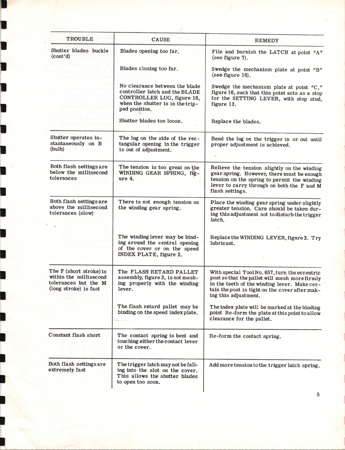
fast
Shutter
Excessive
Blade
Insufficient
Insufficient
(on
er)
Gear
blades
controller
speeds
.
train
CAUSE
binding.
retard
retard
pallet
1/10
dirty.
sector
binding.
sector
engagement
second
travel.
travel.
or
slow-
Remove and
essary,
Swedge
the
ure
Reform
more
mechanism
Be
File
trolling
Remove
in
stud.
Check
figure
COMPLETE.
Clean
area
1).
clearance
sure
the
the
area
the
replace
the
controlling
the
diaphragm
the
speed
the
material
of contact with
for
bind
6,
against
gear
clean
the
speed
plate.
blade
control
fast
of
train
REMEDY
the
shutter
blades.
control
the
between
controller
speed (see
on
the
the
the
thoroughly.
blades.
RING,
slow speed (see
retainer
the
plate
is
ringat
PALLET BRACKET,
retard
the
figure
speed
the
pallet .bracket
figure
plate
flat.
area
1).
control
gear
If
nec-
2,
at
fig-
to
allow
and
the
con-
ring
PLATE
I
I
I
I
I
Shutter
Figure
blades
1
buckle
Too much
drive
NOTE:
may
singly
Loose
MECHANISMPLATE,figure 13.
LAD
B
contact stud,
Shutter
Mechanism
Blade
tight on
mechanism
Too
mechanism
phragm
WINGS
to
due
Burr
retainei-plate
sembled.
tension
spring.
The
contribute
following conditions
or
in combination.
studs
on
E CONTROLLER with
blades
plate
controller
the
plate
much
plate
retainer
ASSEMBLED,
retainer
or
roughness
on
to
blade buckle
shutter
figu~
e
not
flat.
not flat".
too
central
.
play
between
and
PLATE
plate
on
with wings
the
blades
14, not flat.
loose
hub of
the
figure
being bowed.
diaphragm
main
or
or
too
the
the
dia-
WITH
14,
as-
Replace
Replace
studs
avoid swelling
Straighten
Replace
Replace
Replace
Replace
wings
Replace
the
main
the
on
the
or
the
blades.
the
mechanism
the
blade
the
diaphragm
assembled.
the
plate.
drive
shutter
mechanism
the
replace
blades.
tops
of
the
controller
spring.
plate
the
studs.
blade
plate.
.
retainer
Restake
carefully
controller.
plate
the
to
with
4
I
Page 5
TROUBLE
CAUSE
REMEDY
Shutter
(cont'd)
Shutter
stantaneously
(bulb)
Both
below
tolerances
Both
above
tolerances
blades
operates
flash
the
flash
the
settings
millisecond
settings
millisecond
(slow)
buckle
in-
on B
are
are
Blades
Blades
No
controller
CONTROLLER LUG,
when
ped
Shutter
The
tangular
is
The
WINDING GEAR SPRING,
ure
There
the
opening
closing
clearance
the
position.
blades
lug on
out
of
tension
4. .
is
winding
too
too
between
latch
and
shutter
opening
adjustment.
riot enough
the
is
gear
is
too
side
in
too
spring.
loose.
far.
far.
the
the
figure
in
the
of
the
great
tension
BLADE
the
trigger
blade
16,
trip-
rec-
on t e
fig-
on
File
and
(see
figure
Swedge
(ses
figure
Swedge
figure
16,
for
the
figure
Replace
Bend
the
proper
Relieve
gear
spring.
tension
lever
to
flash
settings.
Place
the
greater
ing
this
latch.
burnish
the
the
such
SETTING LEVER, with stop stud,
13.
the
lug on
adjustment
the
on
the
carry
winding
tension.
adjustment
the
7).
mechanism
16).
mechanism
that
this
blades.
the
is
tension
However,
spring
through
gear
Care
not
LATCH
plate
plate
at
point
acts
trigger
achieved.
slightly on
to
there
permit
on
both
spring
should
to
disturb
in
must
under
be
at
point "A"
at
point "B"
point "C
as
or
out until
the
winding
be
the
winding
the
F 'and M
slightly
taken
the
a stop
enough
dur-
trigger
,"
I
The F (short
within
the
millisecond
tolerances
(long
stroke)
Constant
Both
extremely
flash
flash
settings
fast
stroke)
but
is
short
the
fast
is
M
are
The
winding
ing
around
of
the
cover
INDEX
The
assembly,
ing
lever.
The
binding on
The
touching
or
T he
ing into
This
to
PLATE,
FLASH RETARD
figure
properly
flash
retard
the
contact
either
the
cover.
trigger
the
allows
open
too
lever
the
or
with
speed
spring
latch
slot
the
soon.
may
central
on
figure
3,
is
pallet
the
contact
may
on
shutter
be
opening
the
2.
PALLET
not
the
winding'
may
index
is
bent
not
be
the
bind-
speed
mesh-
be
plate.
and
lever
fallcover.
blades
Replace
lubricant
With
post
in
tain
ing
T he index
point
clearance
Re-form
Add
spec
so
the
teeth
the
this
Re-form
more
that
the
post
adjustment.
WINDING LEVER,
.
ial
Tool
No. 657,
the
pallet
will
of
the
winding
is
tight
on
the
plate
will
be
plate
pallet.
spring.
tothe
marked
trigger
for
the
the
contact
tension
the
turn
mesh
lever.
at
this
figure
the
cover
at
point
latch
ecc
more
Make
after
the
2.
Try
entric
firmly
cer-
mak-
binding
to
allow
spring.
5
•
Page 6
TROUBLE
CAUSE
I
I
REMEDY
flash
Both
extremely
Shutter
lamps
flasholder
tact
will, when
is
camera
will not
when
with
held
settings
fast
(cont'd)
all
metal
is
in
camera,
flasholder
away
are
flash
con-
but
from
The
end
back,
the
the
cover,
enough
of
the
strip.
bent
When
on
permit
far
blades.
Breakdown
ground
the
toward
latch
the
trigger
to
in
trigger
the
falls
into
bent
latch
to
trip
the
insulation
latch
is
trigger.
the
slot
will
go down
shutter
in
Re-form
ing
After
be
open
1.
2.
3. Holding
the
open while
There
between
arrestor
shutter
the
it
slightly
the
checked
before
Set
the
Set
the
shutter.
should be a
the
case.
end of
the
trigger
toward
shutter
to
see
the
shutter.
winding
the
The
the
connector
button and any
If
has
been
if
the
winding
lever.
winding
shutter
winding
resistance
not,
replace
the
pin
winding
assembled,
shutter
lever
lever
blades
lever
is
of 10,000
nearest
other
the
latch
by
gear.
blades
opens
down,
should not
down.
the
spot on
ground
bend-
it
can
will
them.
release
ohms
blade
the
strip.
I
I
6
Page 7
•
I
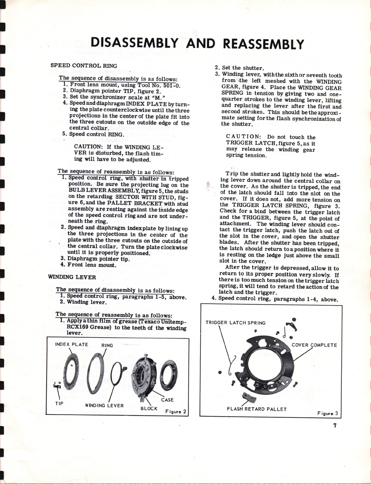
SPEED
The
sequence
1.
Front
2.
Diaphragm
3.
Set
4. Speed and
ing
projections
the
central
5. Speed
The
sequence
1.
Speed
position.
BULB LEVER ASSEMBLY,
on
ure
assembly
of
neath
2. Speed and
the
plate
the
until
3.
Diaphragm
4.
Front
WINDING
The
sequence
1.
Speed
2. Winding
DISASSEMBLY
CONTROL RING
of
disassembly
lens
mount,
pointer
the
synchronizer
diaphragm
the
plate
counterclockwise
in
three
cutouts
collar.
control
CAUTION:
VER
is
disturbed,
ing will have
of
reassembly
control
Be
sure
the
retarding
6,and
the
are
the
speed
control
the
ring.
diaphragm
three
projections
with
the
central
LEVER
it
is
lens
control
lever.
collar.
properly
pOinter
mount.
of
disassembly
using
the
center
on
RING.
If
the
to
be
ring,
the
SECTOR WITH STUD,
PALLET
resting
three
ring,
is
Tool
TIP,
figure
scale
at
INDEX
the
WINDING
the
adjusted.
with
ring
cutouts
Turn
positioned.
tip.
paragraphs
PLATE
of
the
outside
flash
is
as
shutter
projecting
figure
BRACKET with
against
and
index
plate
in
the
on
the
is
as
follows:
No. 501-0.
2.
"M.»
by
until
the
plate
edge of
LE-
tim-
follows:
in
lug on
5,
the
the
tnside
are
not
by lining up
cehter
the
outside
plate
clockwise
as
follows:
1-5,
AND
turnthree
fit
into
the
tripped
the
studs
fig-
stud
edge
under-
of
the
of
above.
REASSEMBLY
2. Set
the
shutter.
3. Winding lever, with
from
. ,
the
left
GEAR,
SPRING
quarter
and
second
mate
the
ing
the
of
cover.
the
Check
and
attachment.
tact
the
blades.
the
is
slot
return
there
spring,
latch
4. Speed
figure
in
tension
strokes
replacing
strokes.
setting
shutter.
CAUTION:
TRIGGER LATCH,
may
release
spring
tension.
T
rip
the
lever
cover.
the
slot
latch
resting
After
shutter
down
As
latch
should
If
it
TRIGGER LATCH SPRING,
for
a bind
the
TRIGGER,
the
trigger
in
the
After
should
on
in
the
cover.
the
trigger
to
its
is
too
much
it
will
and
the
control
the
meshed
4.
Place
by giving two and
to
the
the
lever
This
for
the
flash
Do
not
figure
the
winding
and lightly hold
around
the
shutter
fall
does
not, add
between
figure
The
winding
latch,
cover,
the
shutter
return
the
ledge
is
proper
trigger.
tend
ring,
pOl?ition
tension
to
paragraphs
sixth
with
the
winding
after
should
synchronization
touch
the
central
is
into
the
5,
lever
push
and
open
ha,s
to a position
just
depressed,
on
retard
or
seventh
the
WINDING
WINDING
betheapproxi-
5,
as
gear
tripped,
the
more
trigger
at
the
been
above
very
the
the
lever,
the
first
the
it
the
collar
slot
tension
figure
the
point of
should
latch
the
tripped,
where
the
allow
slowly.
trigger
action
1-4,
GEAR
lifting
wind-
the
on
shutter
above.
tooth
one-
and
of
on
end
the
on
3.
latch
con-
out of
it
small
it
to
If
latch
of
the
I
I
I
The
sequenc~
1.
Apply a
RCX169
lever.
INDEX
PLATE
TIP
of
reassembly
thin
film
Grease)
RING
WINDING
Of
grease
to
LEVER
the
is
as
(Texaco
teeth
BLOCK
follows:
Unitemp-
of
the
winding
Figure
TRIGGER
2
LATCH
SPRING
LETE
Figure
3
7
Page 8
COVER
COMPLET~
The
sequence
1.
Speed
2. Winding
3. TRIGGER LATCH SPRING,
Lift
4.
figure
COMPLETE,
of
the
ure
5. High
HIGH
6. FLASH RETARD
of
disassembly
control
up
the
5,
latch
2.
speed
SPEED
ring,
lever, paragraph
loose
sufficiently
figure
until
spring
SPRING .
end
it
3.
7.
Cover
.complete.
The
sequence
1.
Cover
Set
2.
3.
Trigger
latch
TACT
sure
4.
Trigger
ly. Lift
trigger
between
secure
the
latch
grease
applied -at
5. Winding
Flash
6.
stud. Pull
see
lever.
until
Tool
get
will
of
complete
the
shutter.
latch, with
contacting
LEVER
the
latch
latch
the
latch
the
the
outside
should
(Texaco
the
lever,
retard
down
that
the
If
it
the
pallet
No. 657.
the pallet
cause
the
reassembly
.
the
COMPLETE,
does
spring;
loose
until
latch
and
spring.
edge
be
burnished
Unitemp-RCX169
point
paragraphs
pallet
the
pallet
does
not,
is
Care
too
action
•
is
paragraphs
2,
figure
ofthe
TRIGGER LATCH,
to
clear
3. Move
is
clear
of
CAM,
PALLET
not
end
it
Place
of
of
assembly
winding
falls
closer
close
ST
figure
assembly,
is
as
the
long
inner
edge
bind.
do not
fasten
of
the
is
at a point
the
central
the
the
trigger
and a thin
spring
1-3,
lever
into
every
turn
the
to
the
should
to
the
of
the
lever
AR
WHE
CLUTCH ASSEMBL Y
as
follows:
1-5,
page
page
7.
3.
the
COVER
the
loose
the
CASE,
7,
and
figure
follows:
bent
end of
of
the
CON-
figure
spring
spring
contact.
on
eccentric
be
lever,
EL ASSEMBL Y
it
collar.
latch.
page
the
eccentric
slowly
tooth
lever,
taken
to
be
8.
secureover
half
Then
against
film
Grease)
7.
of
using
not
as
rough.
7.
end
fig-
the
the
Be
the
way
The
of
and
the
stud
to
this
NOTE: Be
is
tight
stud
is
made.
7. High
8. Winding
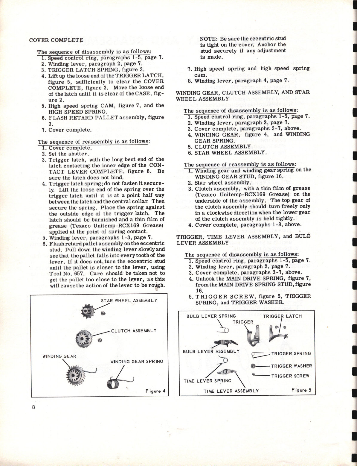
WINDING GEAR , CLUTCH ASSEMBLY, AND STAR
WHEEL
The
1.
2. Winding
3.
4. WINDING GEAR,
5. CLUTCH ASSEMBLY.
6. STAR
The
1.
2.
3.
4.
TRIGGER,
LEVER
The
1.
2. Winding
3.
4. Unhook
5.
BULB LEVER SPRING
speed
cam.
ASSEMBLY
sequence
Speed
Cover
G EAR SPRING.
sequence
Winding
WINDING GEAR STUD,
Star
wheel
Clutch
(Texaco
underside
the
clutch
in a clockwise
of
the
Cover
TIME
ASSEMBLY
sequence
Speed
Cover
from
the
16 . .
TRIGGER
SPRING,
sure
the
eccentric
on
the
cover.
securely
lever,
of
control
lever,
complete,
WHEEL
of
gear
assembly,
Unitemp-RCX169
clutch
complete,
of
control
lever,
complete,
the
MAIN DRIVE SPRING STUD,
and
if
any
spring
disassembly
reassembly
assembly.
of
the
assembly
assembly
LEVER
disassembly
MAIN DRIVE SPRING,
SCREW,
TRIGGER
and
paragraph
ring,
paragraphs
paragraph
paragraphs
figure
ASSEMBLY.
and
winding
with a thin
assembly.
should
direction
ring,
paragraph
TRIGGER
is
paragraphs
ASSEMBLY,
paragraphs
paragraphs
figure
when
figure
WASHER .
stud
Anchor
adjustment
high
speed
4,
page
is
as
2,
page
3-7,
4,
and
is
as
follows:
gear
spring
16.
film
Grease)
The
turn
the
held
tightly.
1-8,
is
as
2,
page
3-7,
5, TRIGGER
the
spring
7.
follows:
1-5,
page
7.
above.
WINDING
of
grease
on
top
gear
freely
lower
above.
and
BULB
follows:
1-5,
page
7.
above.
figure
figure
on
only
gear
7.
the
the
of
7.
7,
I
I
8
WINDING
GEAR
WINDING
~
GEAR SPR
Figure
ING
BULB LEVER ASSEMBLY
TIME
LEVER SPRING
4
TIME
LEVER ASSEMBLY
~
TR
IGGER SPR
o TRIGGER
~TRIGGER
WASHER
SCREW
Figure
ING
5
Page 9

•
•
6. TRIGGER,
LEVER
and
The
sequence
1.
With
the
trigger
the
bulb
trigger.
the
time
trigger
bly,
three
of
tweezers
holes.
lever
and
the
TIME
The
gainst
2.
Trigger
screw.
the
end
rest
3. Hook
onto
4.
Cover
RET
ARD GEAR TRAIN
•
The
sequence
'
I.
Speed
2. Winding
Cover
3.
4. Unhook
SPRING,
5.
Retard
6.
Retard
7.
RetardGEAR
8.
RetardGEAR
9. ESCAPEMENT
assembly.
Retard
10.
11.
PALLET
the
pallet
SECTOR SPRING GEAR
ECTOR
TIME
SPRING, BULB
BULB
of
the
bulb
lever
Place
lever
and
with
the
parts
With
springs
the
short
levers,
AND BULB
long
ends
the
case.
washer,
Lift
of
it
against
the
loose
the
main
complete,
of
control
lever,
complete,
the
figure
GEAR
gear
PALLET.
BRACKET
bracket
SCREW
j " _
LEVER
LEVER
reassembly
lever
with
the
assembly
the
spring
the
top
spring
by
inserting
down
through
the
long
turned
ends
resting
guide
LEVER
of
the
trigger
the
long end of
the
main
the
end of
drive
paragraphs
disassembly
ripg,
paragraph
paragraphs,
retard
6. .
PLATE
PLATE
WITH
WITH
WHEEL
. .
spring.
PLATE
ASSEMBLY,
LEVER
SPRING.
is
as
spring
oval
time
of
ends
the
stud.
spring
paragraphs
PALLET
NO.2
NO.3
underneath,
hole up
in
the
lever
between
the
bulb
facing
in a clockwise
springs
drive
the
COMPLETE.
with
up.
one
prong
the
of
the
against
parts
STUD,
spring,
the
spring
main
stud.
is
as
2,
page
SCREWS.
PINION
PINION
with
stud
SCREW
down
~
PLATE
ASSEMBLY,
follows:
and
opening
assembly
the
top
lever
assem-
Grasp
of a
center
time
and
direction
the
lugs
over
figure
should
1-8,
3-7,
assembly
rest
and
trigger
spring
stud,
drive
spring
page
follows:
1-5,
page
7.
page
BRACKET
assembly.
assembly.
No.3
pinion
Figure
COMPLETE
TIME
hold
insert
on
the
and
of
the
all
pair
of
the
bulb
on
the
16.
a-
over
and
8.
7.
8.
and
NOTE:
dirty,
ing
and
thoroughly
12.
Retarding
tarding
Set
13.
14.
The
10.
11.
12.
13.
6
14.
the
Retarding
sector
sequence
1.
Retarding
sector
at
the
Retarding
2.
3.
Place
inner
SPR,ING BUSHING,
4. With
down,
et
with
the
spring
Place
spring
STUD,
should
5.
Retard
6.
Escapement
bly.
7.
Retard
Retard
8.
9.
Retard
the
gear
Retard
bracket.
Lift
the
teeth
pass
tarding
are
meshed
be
approximately
case.
Remaining
Put
the
plaCing
inside
complete
Cover
If
the
clean
holes
all
the
•
SECTOR SCREW. Unhook
SECTOR SPRING.
shutter.
sector
spring.
of
sector
spring,
top
.
sector
the
long end of
side
the
short
place
stud
the
pallet
on
the
figure
rest
pallet.
gear
gear
gear
faCing
gear
up
the
of
freely
sector
pallet
the
long
edge
. .
complete,
retard
the
retard
in
the
mechanism pla
parts
.
with
reassembly
with
with
screw.
of
the
blade
end of
the
spring
assembly.
to
extend
bracket
PALLET
16.
The
against
wheel
with
NO.3
with No. 2
plate
complete
the
plate
gear
end
the
retarding
under
so
that
the
outer
1/8
retard
of
bracket
the
gear
end
lug on
paragraphs
of
the
the
the
figure
the
inside
out,
the
with
shutter
screw
of'
the
edge
inch
of
gears
gear
stud
stud
long end of
pallet
Allow
and
BRACKET SPRING
long end of
case.
No.4
pinion
pinion
the
gear. Place
when
plate
spring
the
the
are
bear-
gear
train
and
the
is
as follows:
and
the
spring
controller
7.
bracket
the
the
toward
the
pallet
pinion
assembly
assembly.
, with
blades.
near
gear
sector
the
of
the sector
from
screw.
in
spring
retard
1-8,
against
pallet
the
the
the
tension
against
te
the re-
retarding
retarding
the
spring
LATCH
spring
brack
long end of
the
case.
bracket
the
spring
assem-
teeth
pall
plate
with
the
gear
shutter
gear
plate
page
the
-
.
of
e t
until
stud
re-
teeth
will
by
the
8.
•
•
\l
GEAR WITH NO.
GEAR WITH
NO.3
ESCAPEMENT WHEEL
•
PALLET
SECTOR WITH STUD
'~N
!
PINION
BRACKET
PALLET
BRACKET
SPRING
MAIN DRIVE ASSEMBLY
The
sequence
1. Speed
2. Winding
Cover
3.
4. Unhook
the
control
lever,
complete,
the
main
of
disassembly
ring,
paragraph
paragraphs
LATCH SPRING,
drive
LATCH.
is
as
paragraphs
2,
page
follows:
1-5,
3- 7,
figure
page
7.
page
7,
7.
8.
from
9
Page 10

I
I
5. Unhook
MAIN DRIVE SPRING STUD,
6. Set
7. MAIN DRIVE ASSEMBLY,
is
The
sequence
1. Apply a
RCX169
assembly
the
DRIVE STUD,
ure
SPRING, and on
the
This
before
2. Main
being
in
3.
Close
toward
cutout
around
latch
tip
4. Main
Cover
5.
~
LASH
CONTACT PARTS
The
sequence
1.
Speed
2. Winding
3.
Cover
4.
Retard
5. Winding
graphs 4 and
6. CONNECTOR PINS,
635.
Connector
7.
8.
Ground
SCREW,
9.
Disengage
nism
CAM
the
MAIN DRIVE SPRING
the
shutter
attached
thin
SETTING
7,
at
RETARDING SECTOR STUD,
area
applying
drive
sure
the
assembly.
the
the
part
the
spring
of
the
drive
complete,
control
complete,
gear
plate.
LATCH
.
the
main
of
reassembly
film
Grease)
where
LEVER,figure
figure
the
point
of
the
the
assembly
to
fit
shutter
BLADE CONTROLLER LUG.
of
the
lug.
against
latch.
sp:ring.
.
of
disassembly
ring,
lever,
paragraph
train,
gear
and
5,
page
BLOCK,
CONTACT
figure
SPRING BUSHING
the
RESISTOR
8.
figure
drive
spring
of
to
it
of
the
latch
the
Place
paragraphs
paragraphs
is
grease
the
engages
blades. Push
latch
paragraphs
c.1utch
figure
(Texaco
slot
on
16; on
contact
latch
where
should
lubricant.
on
the
setting
will
the
the
vertical
is
paragraphs
2,
assembly, para-
8.
figure
8,
2.
STRIP
from
~
from
figure
as
the
13;
the
with
main
lever
loose
1-8,
as
page
3-7, page
using
16.
7,
to
.
follows:
Unitemp-
the
main
stop
stud
ontheMAIN
LATCH,
the
LATCH
it
contacts
figure
be
burnished
drive
stop
the
come
to
end of
lug
on
page
follows:
1-5, page
7.
4-11,
page
Tool
CONNECT6R
the
mecha-
F i
the
which
drive
on
fig-
16.
stud,
stud
latch
The
rest
the
the
8.
7.
8.
9.
No.
gure
10. Holding
262,
using
screw
11. CONTACT SPRING,
GROUND
Remove
the
12. CONTACT
13.
Shutters
assembled
remove
the
move
plunger
sulating
SPRING
the
The
sequence
1.
If
the
on
long end of
the
the
tact
spring
tact
LEVER
Bend
spring
2.
Contact
LEVER
contact
the
spring
tenSion,
CONTACT
7
LEVER
the
remove
Tool
.
CON:!'
the
case
INSULATOR.
of
the
end
of
the
assembly,
SLEEVE.
and
CONTACT
a new
contact
contact
the
contact
long end of
outside
lever
around
lever
SPRING on
the
last
clockwise
lever
STUD,
lever
shutter
in a clockwise
and
LEVERSPR
~
~
.-
BUSHING
CONTACT
the
No. 503L.
ACT STRIP
case
LEVER
the
flash
as
follows: Using
TERMINAL NUT,
the
PLUNGER ASSEMBLY.
ca~e
INSULATOR WASHER.
the
LEVER
of
reassembly
LEVER
LEVER
the
the
edge
latch.
the
tail.
1/8
complete
figure
spring
blades.
rest
EVER
CONTACT
CONTACT S;REW
SCREWwithTool
CONTACT SCREW NUT ,
Remove
to
which
INSULATOR WASHER and
COMPLETE.
receptacle
and
the
Remove
case
INSULATOR. Remove
COMPLETE.
lever
spring
of
Form
Then
inch
at
it
ING
LATCH
is
is
LATCH SPRING,
BUSHING, with
at
spring
the
spring
the
vertical
place
the
contact
of
the
least
on
16.
should
Tur
'n
the
direction
in
the
groove
SPRING
LEVER
the
is
fastened
and
the
type
Tool
figure
terminal
the
CONTACT
as
follows:
to
be
used,
the
bottom.
and
rest
lug on
short
end of
part
of
the
CONTACT
lever
long end of
15
degrees
the
CONTACT,
The
ends
face
in,
long end
to
place
in
COMPLETE
CONTACT
CONNEC/TOR
No.
contact
the
resistor.
are
dis-
No. 503J,
9, on
Re-
the
boayin-
place
figure
8,
the
Lift
it
against
the
con-
the
the
con-
bushing.
the
.
of
the
toward
of
the
it
in
the
case
Figure
STRIP
SCREW
I
.
8
10
HI
GH
MAIN
SPE
ED
DRIVE
~
SPRING
o
ASSEMBLY
/
\-
~
•
"'
~
MAIN
LATCH
---LATCH
A
DRIV~
SPRING
SPRING
CONT ACT
ONT ACT SPRING
INSULATOR
--0
K
/ INSULATOR WASHER
SCREW
NUT CONNECTOR PIN
GROUND
CONTACT
H
STRIP
Page 11

I
I
I
I
~
~
)V~.,/
"
SLEEVE
INSULATOR
TERMINAL
Form
the
vertical
CAUTION:
is
burnished
that
condition.
3.
Contact
washer
tact
end
contact
placing
screw
nut.
tact
screw
nut with
4. Ground
5.
Connector
6.
Connector
7.
Secure
8.
Winding
graphs
Retard
9.
10.
If
the
the
assembled
of
the
spring
push
sembly
Fasten
the
opening
shu
the
plunger
the
plunger
plunger
terminal
Place
"
insulator.
and
11.
Trip
its
gainst
CONTACT
----I
---0
NUT"
short
part
of
The
spring.
between
of
the
screw.
the
case
To
with
Tool
No. 503L.
contact
block.
pins.
the
resistor.
gear
1 and 3,
gear
train,
tt
e r
type,
insert
assembly
body
insulating
case
Position
over
the
the
threaded
through
the
plunger
shutter
action
shutter
LEVER
~
end
of
the
contact
contact
and
must
Place
the
shutter
contact
Secure
insulator
tighten
Tool
strip
and
clutch
page
paragraphs
is
of
in
parts
insulator
assembly.
opening
the
with
and
at
by placing one
SETTING LEVER,
COMPLETE
~
---
PLUNGER ASSEMBLY
~
INSULATOR
CONTACT SPRING
the
spring
lever
lever
remain
the
case
spring
the
and
the
nut, hold
No. 262 and
connector
assembly,
8.
the
flash
the
threaded
the
collar
sleeve.
in
the
washer
Replace
the
end
in
the
end
of
opening
the
the
same
around
tail.
tail
in
case
and
and
insert
spring
the
screw.
4-13,
receptacle
end of
end of
Then
body
terminal.
on
of
the
shutter
the
plunger
tit
the
terminal
time
Figure
9
WASHER
the
insulator
the
con-
the
by
re-
contact
the
con-
turn
the
para-
page 9.
the
the
insert
the
end
the
case
contact
base
as-
spring.
nut.
retard
finder
a-
figure
13.
Observe
LER
CONTACT
slight
before
spring
of
the
12.
Cover
FLASH SYNCHRONIZATION
After
the
shutter
ed
to
see
if
shutter
slowly.
lease
must
trip
The
blades
in
the
the
shutter
winding
the
trigger.
whUe
do, '
refer
extremely
Check
latch.
must
shutter
must
position
The
with
reliable
ances
chronization
F
M (long
*From
fil'st
begin
FLASH SHUTTER CONTACT CONVERSION KIT
A
more
been
achieved
contact
discarded
replaced
Contact
Parts
OLD-STYLE FLASH CONTACT PARTS
The
1.
2. Winding
3. CONNECTOR PINS,
the
blades
Set
the
the
winding
the
shutter
will open while
cover
plate.
and
lever
the
winding
to
the
fast;"
the
When
the
be locked
has
been
return
fully and
.
flash
settings
of
(short
List
shutter
the
delayed
with
stroke)*
stroke)*
instant
to
satisfactory
parts.
are
by
the
Conversion
No. 1-1490A.
sequence
Retard
graphs 4 and
No. 635.
whether
contact
the
b 1 a
does
not
spring
operation
toward
complete,
is
winding
when
the
shutter
lever
shutter
must
be
To
the
winding lever. While holding
in
the
fully wound
The
shutter
lever
"TroubleChart-Bothflashsettings
see
page
shutter
in
the
actuated
on
testing
the
of
contact
show light.
by a
change
The
old-style
no
longer
parts
furnished
Kit No. 121349 - Supplement
of
disassembly
gear
train,
gear
5, page 8. .
the
BLADE CONTROL-
STU
D,
with
des
touch
paragraphs
assembled,
lever
trigger
and
very
blades.
checked
the
check
is
being held down.
5.
of
is
not
unwound position.
with
become
the
action
flash
3t -5t
12
until
operation
in
available.
paragraphs
and
clutch
figure
the
contact
are
fully open.
the
stud,
the
stud.
it
will
is
the
winding lever.
slowly.
to
see
latch
is
for
this
position,
blades
the
shutter
should not open
winding
set,
the
the
winding
locked
should
equipment.
in
the
shutter
bulbs
are
milliseconds
- 16
milliseconds
the
of
the
design
parts
in
the
is
assembly,
figure
1-8,
must
always
released
still
condition,
winding
in
shutter
the
which
They
Flash
as
10,
16,
spring
bend
page
be
The
if
the
in
lever
After
the
be
The
as
shutter
of
the
are
are
follows:
4-11,
using
makes
If
the
check-
trip
very
lever
shutter
the
depress
If
safety
lever
lever,
unwound
timed
toler-
for
syn-
follows:
blades
flash
to
to
Shutter
page
para-
Tool
just
the
end
8.
the
Re-
slot
set
the
they
the
it
.
has
be
be
to
9.
I
I
11
Page 12

4.
Disengage
nism
5. CONTACT
6.
Connector
7. Ground CONTACT STRIP
SCREW,
8. Holding
with
SCREW
the
contact
ER,
INSULATOR.
contact
9. DETENT SPRING AND
DETENT SPRING
and
SEMBLY.
10. CONTACT ESCAPEMENT WHEEL.
11. SHUTTERS
TYPE
Tool
figure
SEMBLY.
WASHER,
minal
tact
the
CONTACT. SCREW NUT,
503L.
tact
the
TACT
NEW-STYLE FLASH CONTACT PARTS
The
sequence
1.
Place
figure
with
and
DETENT
SPRING AND
the
RESISTOR
plate.
LEVER
BLOCK,
figure
the
CONTACT SCREW,
Tool
No. 262,
NUT,
screw,
the
CONTACT SPRING,
spring.
the
DETENT SPRING
OF
are
disassembled
No. 503J,
11, on
Remove
the
body
insulating
end
of
the
Remove
spring,
case
the
facing
case
INSULATOR. Remove
LEVER
of
assembly
the
contact
8, on
long
the
COMPLETE.
figure
8.
remove
using
Tool
the
Remove
AND
THE
remove
the
end
plunger
CONTACT SPRING,
the
CONTACT SCREW,
INSULATOR WASHER,
COMPLETE.
LEVER
the
contact
end
of
the
shutter
ROLLER
from
2.
CONNECTOR
the
No. 503L.
case
insulator
and
the
resistor
ROLLER
ROLLER
AND
ROLLERAS-
FLASH
of
the
assembly,
SLEEVE.
RECEPTACLE
as
follows:
the
TERMINAL NUT,
the
PLUNGER AS-
case
INSULATOR
and
using
is
as
follows:
LATCH SPRING,
LEVER
spring
blades.
WASHER
at
Lift
'o~
DETENT
ROLLER
CONT ACT ESCAPEMENT WHEEL
CONT
COMPLETE
CONTACT
SPRING
ASSEMBLY AI\
ACT
LEVER
~
CONT ACT
WASHER
INSULATOR
SCREW
--0
--0
~
SCREW
AND
~
----w-
~ENT
ROLLER
t)
~ 0 ~
~
Sl~~\
II 0
~
NUT
.,
\
f}
, CONNECTOR
CONNEIi:TOR PIN
CONTACT
CONTACT
"
SPRING
the
mecha-
figure
CONTACT
Remove
WASH-
the
case
from
BUSffiNG,
WASHER,
Using
the
ter-
On
the
con-
remove
Tool
con-
the
CON-
BUSHING,
the
bottom
the
long
Figur
SPRING AND
- BUSHING
STRIP
SCREW
10,
the
No.
and
e 10
'lr
end of
the
spring
and
rest
it
against
side
edge of
lever
latch.
around
tail.
T hen
SPRING on
the
last
clockwise
2.
Contact
LEVER
contact
the
shutter
spring
tension,
Form
the
vertical
CAUTION:
is
burnished
that
Contact
3.
washer
tact
end of
contact
4.
Contact
the
screw
5.
Ground
6. New
7.
8.
9. Winding
10.
11. SHUTTERS
Figure
connector
Connector
Secure
the
mechanism
of
the
graphs
Retard
TYPE
are
the
contact
as
described
Insert
insulating
bled
parts
case
insulator
of
the
11
INSULATOR--;~
/'
CONTACT
SCREW
the
spring
Form
the
vertical
1/8
at
lever
STUD,
lever
in a clockwise
and
short
part
condition.
spring
between
the
screw.
screw
in
contact
pins.
the
looped
resistor
gear
1-3,
gear
reassembled
lever
the
collar
sleeve.
in
plunger
'"
q:--
~
~
the
place
the
the
contact
inch
of
least
15
complete
figure
spring
blades.
rest
it
end of
of
the
Thecontactlevertail
and
by
placing
the
contact
nut,
using
position
strip
block.
wire
plate
to
the
and
page
8.
train,
OF
THE FLASH
spring
in
paragraphs 1 and
end of
the
terminal
washer
assembly.
CONTACT
CONT ACT
/
/
INSULATOR
NUT
lug
on
short
part
the
Turn
in
contact
must
shutter
'.
clutch
paragraphs
Then
end of
of
the
CON T ACT
lever
bushing. Bend
long end
degrees.
on
the
16.
The
should
the
connector
LEVER
CONTACT
face
the
direction
groove
the
spring
lever
remain
the
case
spring
Tool
with
No. 503L. Hold
Tool
end of
Solder
ground
assembly,
RECEPTACLE
as
follows:
and
the
the
insert
body.
on
the
Replace
COMPLETE
SCREW
long end of
~
WASHER
PLUNGER ASSEMBLY ·
the
the
the
contact
LEVER
ofthe
CONTACT
ends
in,
to
place
in
the
around
tail.
in
case
insulator
and
the
and
insert
No. 262.
screw.
the
resistor
the
other
contact
4-13,
Replace
contact
2 above.
terminal
the
assem-
Replace
threaded
the
SPRING
TE?NA
out-
contact
spring
lever
spring
of
the
toward
the
it
in
case.
the
con-
the
to
end
st'rip
para-
page
9.
lever
body
the
'end
con-
.L NUT
~
I
I
I
I
12
Page 13

tact
12.
spring,
plunger
spring.
nut. On
replace
end
facing
washer
case.
spring
tact
screw
the
washer.
using
Tool
in
position
Trip
the
its
opening
gainst
13.
Observe
LER
CONTACT
slight
contact
fore
the
does
not
spring
Place
against
the
with
the
extending
Secure
the
the
over
in
the
contact
case
out.
Replace
the
opening on
the
the
the
Replace
through
spring
end of
insulator
contact
washer
opening
the
No. 503L while holding
with
Tool
No. 262.
shutter
blades
touch
toward
action
shutter
whether
with
are
the
the
and
at
by
placing
SETTING
the
ST
U D,
the
contact
fully open.
spring,
stud.
the
threaded
the
end of
and
contact
BLADE CONTROL-
bend
13. STAR WHEEL ASSEMBLY,
14.
Replace
the
cover
complete
lever.
15.
Cock
the
release
the
winding
trigger
cover
with a
check
for
trigger
•
the
cover
crease
A
slight
desirable.
.005
-inch
tail
and
engages
in
contact.
is
excessive
controlled
in
or
out.
Allow
position.
see
that
they
close,
tail
toward
driver
shutter;
the
latch
a bind
latch
complete.
the
tension
downward
clearance
that
the'tail.
If
by bending
the
winding
Depress
the
hold
the
blade
then
shutter.
lever
to
must
distinct
between
or
between
on
pressure
There
part
of
The
there
is
clearance,
the
flash
contacts
the
shutter
against
press
At
the
prevent
drop
into
snap.
the
the
If
no bind
the
trigger
must
between
the
trigger
contact
no
clearance
the
the
lever
trigger,
end
of
case,
the
vertical
end of
the
opening
with
the
the
contact
with
the
case
the
inside
the
insert
in
the
spring
screw
the
same
time
one
finger
LEVER,
figure
16,
spring
If
the
end
figure
and
the
same
its
the
If
it
4.
the
trigger
time
return.
slot
does
trigger
trigger
exists,
latch
on
the
be
approximately
the
contact
latch
points
or
spacing
contact
to
go
to
lever
the
and
do not
the
close.
contact
place a screw-
portion
the
in
the
terminal
spring,
collar
insulator
of
the
contact
the
con-
and
nut,
screw
retard
a-
figure
makes
just
be-
the
stud
of
the
winding
to
hold
The
on
the
not,
and
the
latch
and
in-
spring.
spring
is
lever
which
must
be
if
there
may
be
tail
at
rest
watch
to
If
lever
of
the
contact
stud
., and apply
blades
With
prOximately
contact
the
contact
sure
of
at
this
the
lever
the
lever
point.
shutter
.005
latch
lever.
contact
wheel.
While
watch
close
lever
too
If
stoned
must
pressing
the
contacts
at
any
tail
on
far
and
necessary,
at
point
be
square.
time.
the
should
the
"A,"
SHUTTER BLADES
The
sequence
1. Speed
2.
Winding
3.
Cover
4. Winding
wheel
5.
Trigger
bulb
of
control
lever,
complete,
gear,
assembly,
assembly,
lever
assembly,
disassembly
ring,
paragraph
clutch
8.
6.
Retard
7. Main
gear
drive
train,
assembly,
9 .
8.
Flash
contact
parts,
10.
9.
Rear
lens
mount.
10.
Blade
controller
figure 7 and
11. MECHANISM
Diaphragm
12.
the
PLATE,
retainer
ASSEMBLED.
13.
Shutter
blades.
14. BLADE CONTROLLER,
The
sequence
1.
If
necessary,
oughly. Hold
of
reassembly
clean
the
tail
near
the
pressure
tripped,
inch
clearance
spring
This
is
lever
the
trigger
to
make
If
they
contact
be
moved
winding
figure
paragraphs
paragraphs
assembly,
paragraphs
time
paragraphs
paragraphs
paragraphs
paragrapqs
toward
there
lug
to
assure
latch
sure
close,
lever
lever
12.
is
as
2,
lever
contact
and
into
has
back
follows:
1-5,
page
3-7,
4-6,
assembly,
4-14,
lever
the
shutter
must
be
ap-
between
the
side
full
pres-
the
star
down fully,
they
do not
the
contact
been
bent
slightly.
should
Corner
"B"
page
7.
page
8.
and
star
page
8.
4-6,
page
page 9.
4-7,
page
4-13,
page
LATCH SPRING BUSillNG,
LATCH SPRING.
figure
PLATE
the
blades
figure
is
as
shutter
carefully
13.
WITH
14.
follows:
blades
to
WINGS
thoravoid
the
of
be
7.
and
A
Figure
12
PLATE
WITH
WINGS
SETTING
ASSEMBLED
LEVER
SPRING
Figure
13
13
Page 14

them
and
clean
their
bending
a
cause
2.
Blade
soft
-cloth.
corrosion.
controller.
Fingerprints
on
the
surfaces
blades
3. BLADE WITH DOUBLE BLADE BUSHING
and stu(l,
over
LUG,
4.
Proceeding
BLADES WITH STUD,
the
row
5. BLADE
bushing
plate
6.
Diaphragm
bled,
the
mechanism
stud
plate
operate
7. Open
wings and
b I a
mechanism
phragm
9.
The
POINTER and
oughly
(T
exac
recess
lever.
clean
Diaphragm
9.
the
figure
the
stud
figure
14, with
near
17, on
counterclockwise,
wide end of
end of
should
over
and
each
the
preceding
the
stud.
appear
retainer
with
the
cutout
retainer
assembly,
is
plate
for
secured,
the
figure
freely.
the
de
shutter
around
run
blades.
the
the
plate.
wings-
to
shutter
CAS
setting
cleaned.
0 Unitemp-RCX169
in
the
case
Then
wipe
cloth.
pOinter.
projecting
arm
the
hole
the
BLADE CONTROLLER
the
mechanism
in
replace
figure
blade
to
overlap
14, allowing
blade. .
blade
with double
The
back
of
the
mechanism
as
shown
in
plate
with wings
slot
in
the
outer
over
the
PALLET
the
shutter
side
central
This
the
maximum
E,
figure
lever
Apply a
opening
BRACKET with
6.
After
the
blades
Close
the
diaphragm
of a screwdriver
opening
will
open
aperture.
13,
diaphragm
should
thin
film
Grease)
occupied
this
Turn
is
near
by
area
lightly with a
the
pointer
the
cable
the
the
blade
plate.
the
blade
figure
assem-
edge
in
retainer
should
'1
nth
the
be
thor-
of
grease
to
setting
release
until
socket.
10. Setting
LEVER
loose
side
11.
Mechanismplate.
jections
are
After
ring,
should
of
12. Blade
13.
Flash
lever,
end of
of
the
in
position
the
the
operate
the
setting
controller
contact
with one end of
SPRING
attached
the
shutter
on
the
ends
in
plate
is
setting
lever, and
freely.
lever
parts,
spring
case.
See
that
of
the
secured,
spring
latch
paragraphs
to
the
resting
the
the
diaphragm
slots
the
Secure
to
and
latch
the
SETTING
lever
and
against
circularpI'o-
in
tbe
pointer.
the
diaphragm
shutter
the
loose
the
case
spring.
1-11,
wings
blades
stud.
page
10.
14. Main
drive
assembly,
paragraphs
1-4,
page
9.
15.
16.
Retard
Trigger
bulb
gear
assembly,
lever
train,
paragraphs
time
assembly,
1-13,
lever
assembly,
paragraphs
1-3,
page
page
8.
17. Winding
wheel
18.
Rear
gear,
assembly,
lens
mount.
clutch
assemb,ly,
paragraphs
1':'4,
and
page
star
8.
with
will
four
nar-
15.
of
the
dia-
the
the
the
~
end
9.
and
I
PLATE
WITH
WINGS
ASSEMBLED
BLADE
BLADE CONTROLLER
e
RETARDING SECTOR STUD
MAIN
WITH
STUD
BLADE
BLADE BUSHING
BLADE CONTROLLER
DRIVE STUD
BLADE CONTROLLER
CONTACT STUD
WITH
DOUBLE
Figure
Figure
LUG
Figure
14
15
I
16
14
Page 15

KODAK
FLASH
SUPERMATIC
SHUTTER
__
FOR
Shutter
easily
Shutter
open on high
Shutter
KODAK
TROUBLE
does
blades
does
not
remain
speeds
not
set
trip
MONITOR
TROUBLE
TROUBLE
Possible
SEMBLY,
Split
Loose
blades.
Plate
ing on
The
21,
position
been
burr
on TRIGGER AS-
figure
shutter
blade
TRIGGER LATCH,
is
not
released.
blades.
studs
on
the
studs
mechanism
returning
after
the
SIX-20
21.
shutter
loose
or
miss-
plate.
figure
to
its
proper
shutter
CAMERA
CHART
Burnish
the
point
ASSEMBLY,
ReplaCE}
Replace
Replace
avoid swelling
The
trigger
speed
has
It
on
may
the
REMEDY
the
trigger
where
figure
the
shutter
the
shutter
or
restake
latch
index
plate
be
necessary
TRIGGER LATCH
and
it
contacts
24, when
blades.
blades.
the
the
top
of
is
bent and binding on
or
cover.
to
collar
reduce
assembly
the
MAIN
in a set
studs
the
studs.
SPRING,figure
DRIVE
position.
carefully
the
tension
at
to
the
19.
The
winding
not hold when
ter
is
set
Shutter
Shutter
speeds
Figure
speeds
lever
the
slow
17
fast
does
shut-
The
winding
on
the
The
CLUTCH ASSEMBLY,
ure
20,
The
latch
LEVER
is
damaged.
Retard
The
MAIN DRIVE SPRING,
ure
23,
Shutter
Excessive
Insufficient
InsuffiCient
(on
speeds
gear
gear.
is
slipping.
point on
COMPLETE,
gears
dirty.
is
weak.
blades
binding.
retard
retard
pallet
1/10
pj.nion
is
the
CONTACT
figure
sector
sector
engagement
or
slower).
loose
fig-
24,
fig-
travel.
travel.
Replace
Replace
Replace
Remove
Replace
Remove
Swedge
at
the
area
figure
File
the
the
fast
Remove
in
the
area
stud.
the
the
clutch
the
and
the
and
the
speed
cQntrolling
17.)
speed
speed.
material
of
pinion
contact
clean
main
drive
replace
ring
(See
contact
gear
assembly.
assembly.
lever
complete.
the
retard
spring.
the
shutter
control
the
at
the
figure
on
the
speed
with
the
gears.
RING,
slow
area
17.)
pallet
blades.
figure
speed.
control
(See
controlling
ring
bracket
18,
15
Page 16

TROUBLE
Shutter
(cont'd) -
speeds
fast
Gear
train
CAUSE
dirty.
Check
fo'r bind of
figure
COMPLETE.
Clean
22,
the
against
gear
REMEDY
the
the
train
thoroughly.
PALLET
retard
BRACKET,
gear
PLATE
Shutter
blades
buckle
Too
much
drive
spring.
NOTE:
to
Loose
or
27.
B
contact
Shutter
Mechanism
Blade
too
the
Too
mechanism
phragm
WINGS
due
bowed.
Burr
retainer
bled.
The
blade
buckle,
studs
MECHANISM
LAD
E CONTROLLER with
stud,
blades
controller
tight
on
mechanism
muc h play
retainer
ASSEMBLED,
to
retainer
or
roughness
plate
tension
following
singly
on
shutter
PLATE,figure
figure
nof
plate
not
too
the
central
plate.
plate
PLATE
plate's
with wings
on
the
conditions
or
28, not
flat.
flat.
loose
between
and
the
figure
on
diaphragm
assem-
main
in
combination.
blades
flat.
or
hub
or
the
dia-
WITH
27,
being
Replace
may
contribute
Replace
studs
avoid
Straighten
Replace
Replace
Replace
too
loose
plate.
Replace
wings
Replace
the
main
the
on
swelling
assembled.
shutter
the
mechanism
or
the
blades.
the
mechanism
the
blade
or
too
the
diaphragm
the
plate.
the
replace
drive
tops
controller.
tight,
spring
blades.
plate
of
the
the
blade
plate.
replace
retainer
..
Restake
carefully
studs.
controller.
If
it
the
mechanism
plate
is
the
to
still
with
•
Winding
hold
Shutter
stantaneously
(Bulb)
lever
operates
16
does
in-
0 n B
not
Blades
Blades
No
controller
CONTROLLER LUG,
when
ped
Shutter
The
LEVER
is
The
tangular
is
opening
closing
clearance
the
shutter
position.
blades
latch
point
COMPLETE,
broken
lug on
opening
out
of
adjustment.
latch
off.
~
the
too
fat:.
too
far.
between
and
is
too
loose.
on
the
side
in
the
blade
the
BLADE
figure
in
CONT ACT
of
the
the
trip-
figure
the
trigger
29,
24,
rec-
File
and
at
point
Swedge
(See
figure
Swedge
figure
for
the
ure
27.
Replace
Replace
Bend
the
proper
burnish
"A."
the
the
29,
SETTING LEVER with
the
the
adjustment
the
(See
mechanism
29.)
mechanism
such
that
blades.
contact
lug on
the
blade
figure
plate
this
lever.
trigger
is
achieved.
controller
23.)
plate
point
at
at
acts
stop
in
point
point
as
stud,fig-
or
out
LATCH
"B."
"C,"
a stop
until
Page 17

TROUBLE
The
flash
below
the
tolerance
The
flash
above
the
tolerance
setting
is
millisecond
(fast)
setting
is
millisecond
(slow)
CAUSE
tension
T he
WINDING
20.
The
FLASH RETARD PALLET,
figure
erly
with
The
flash
binding on
There
the
winding
The
winding
ing
around
the
of
INDEX
is
too
GEAR SPRING,
19,
is
not meshing
the
winding
retard
the
speed
is
not enough
gear
lever
the
central
cover
PLATE,
or
figure
great
pallet
index
spring.
maybe
on
on
figure
prop-
lever.
may
plate.
tension
bind-
opening'
the
speed
18.
the
be
on
Relieve
gear
spring.
tension
lever
to
With
special
post
so
that
in
the
teeth
tain
the
ing
this
The
index
ingpoint.
clearance
Place
the
greater
ing
this
adjustment
latch.
Replace
REMEDY
the
tension
However,
on
the
spring
carry
through
Tool
No.
the
pallet
of
the
winding lever. Make
post
is
tight on
adjustment.
plate
will
File
the
for
the
pallet.
winding
tension.
the
gear
Care
winding
slightly on
there
to
permit
on
657,
will
the
be
marked
plate
at
spring
should be
not
to
disturb
lever.
the
must
the winding
the
flash
turn
the
mesh
more
cover
after
at
this
point
under slightly
taken
the
Try
lubricant.
winding
be enough
setting.
eccentric
firmly
cer-
mak-
the
gind-
toallow
dur-
trigger
Constant
The
flash
extremely
Speed
loose
control
or
flash
short
setting
fast
.
ring
too tight
is
too
The
contact
and touching
lever
or
the
Insulation
contact
Terminal
The
falling into
This
to
open too soon.
The
bent
When
on
the
permit
far
spring.
trigger
allows
end of
back,
the
cover,
the
enough
breaking
body
the
latch
blades.
Speed and
not
diaphragm
formed
spring
either
cover.
loose.
latch
slot
on
the
shutter
the
trigger
toward
the
falls
the
bent
trigger
to
trip
properly.
may
be
bent
the
contact
down on
the
may not be
the
cover.
blades
latch
is
trigger.
into
the
slot
latch
will
to
go down
the
shutter
index
plate
Re-form
Replace
Restake
Add
Re-form
ing
Afterthe
be
open
1. Set
2. Set
the
the
the
more
the
it
slightly
shutter
checked
before
the
the
contact
contact
terminal
tension
end of
toward
to
see
the
shutter.
winding
to
has
winding
3. Holding the winding
the
shutter. The
not open while
Re-form
plate.
tension
Bow
on
the
speed and
the
the
speed
index
spring.
spring
body.
the .trigger
the
trigger
the
winding
been
assembled;
if
the
shutter
lever
lever.
lever
shutter
the
winding
diaphragm
plate
control
. . '
up
latch
latch
blades
opens
down,
blades
lever
to
place
ring.
spring.
by bend-
gear.
it
them.
release
should
is
down.
index
more
can
will
17
Page 18

SPEED
The
1.
Front
Focusing
2.
3. Speed
ingthe
projections
the
central
4. Speed
The
sequence
1.
Speed
position.
BULB
studs
figure
stud
edge
underneath
2. Speed
the
plate
edge of
COMPLETE,figure
wise
3.
Focusing
4.
Front
WINDING
The
sequence
1.
Speed
2. Winding
The
sequence
1.
Apply a
RCX169
lever.
DISASSEMBLY
CONTROL RING
sequence
three
CAUTION:
VER
ing will have
LEVER
of
disassembly
lens
mount,
mount STOP SCREW,
and
diaphragm
plate
counterclockwise
in
the
cutouts
collar.
control
is
control
LEVER
on
22,
assembly
of
and
three
with
until
lens
control
thin
RING.
If
disturbed,
to
of
reassembly
ring,
Be
sure
ASSEMBLY,
the
retarding
and
the
are
the
speed. control
tl1e
ring.
diaphragm
projections
the
three
the
central
it
is
properly
mount
mount.
of
disassembly
ring,
lever.
of
reassembly
film
Grease)
is
as
follows:
using
Tool
No. 256.
INDEX
center
on
the
the
WINDING
the
be
with
the
PALLET
resting
19.
stop
paragraphs
of
grease
to
the
PLATE
until
of
the
outside
adjusted.
projecting
SECTOR WITH STUD,
index
in
cutouts
collar
Turntheplateclock-
screw.
teeth
plate
LE-
flash
tim-
is
as
follows:
shutter
figure
BRACKET with
against
ring
plate
the
center
on
on
positioned.
is
as
follows:
is
as
follows:
(Texaco
of '
figure
by
turn-
the
three
fit
edge
and
the
the
1-4,
the
into
of
the
in
tripped
lug on
21,
the
inside
are
byUningup
of
outside
COVER
above.
Unitemp-
winding
AND
18.
the
the
not
the
2.
3. Winding
4.
5.
COVER
The
1.
TRIGGER
REASSEMBLY
Set
the
shutter.
lever,
with
the
sixth
or
seventh
from
the
left
meshed
GEAR,
SPRING
quarter
and
second
mate
the
Trip
lever
cover.
the
If
GER LATCH SPRING,
a bind
TRIGGER ASSEMBLY,
of
tact
the
blades.
the
just
return
there
spring,
latch
Speed
Speed
figure
in
strokes
replacing
strokes.
setting
shutter.
CAUTION:
GER
LATCH,figure21,as
release
tension.
the
shutter
down
As
latch
should
it
does
not,
between
attachment.
the
trigger
slot
in
After
latch
should
above
After
the
to
its
is
too
it
will
and
the
control
COMPLETE
sequence
of
control
LATCH
20.
tension
the
for
DonottouchtheTRIG-
the
winding
around
the
shutter
fall
add
The
the
cover,
the
the
small
trigger
proper
much
tend
trigger.
ring,
disassembly
ring,
SPRING
with
Place
the
by giving two
to
the
winding
lever
after
This
should
the
flash
gear
and
lightly hold
the
central
is
tripped,
into
the
moretensien
figure
the
trigger
figure
winding
latch,
push
and
shutter
return
to
slot
is
depressed,
position
tension
to
retard
paragraphs
paragraphs
in
on
the
WINDING GEAR
lever,
the
be
synchronization
it
may
spring
collar
slot
to
19.
latch
21,
lever
the
open
has
been
rest
the
very
the
trigger
the
is
as
follows:
tooth
WINDING
and
one-
lifting
first
the
approxi-
the
winding
on
the
end
on
the
cover.
the
TRIG-
Check
and
at
the
point
should
con-
latch
out of
the
shutter
tripped,
on
the
ledge
cover
. •
allow
it
slowly.
latch
action
of
1-4,
above.
1-4,
above.
and
of
the
of
for
the
I
(0
If
the
18
STOP
INDEX
SCREW
PLATE
RING
SECTOR
~
.
~
WINDING
LEVER
AND
STRAP
~~
' .
Figure
18
Figure
19
•
.......... --FLASH
RETARD
PALLET
Page 19

2. Winding
3. TRIGGER LATCH SPRING,
4.
Lift
LATCH,
COVER
loose
CASE,
5. FLASH RETARD
Cover
6.
The
sequence
1.
Cover
2.
Set
3.
Trigger
latch
TACT LEVER
sure
4.
Trigger
ly.
triggeJ:
between
secure
the
latch
grease
applied
5. Winding
Flash
6.
Pull
that
lever. H
until
•
Tool
get
will
7. Winding
lever,
paragraph
up on
the
Lift
outside
down
the
the
cause
NOT
stud
the
justment
r-
the
loose
figure
COMPLETE,
end of
figure
complete
complete.
shutter.
latch,
contacting
the
latch
latch
the
latch
the
the
should
(Texaco Unitemp-RCX169
at
lever,
retard
pallet
it
the
pallet
No. 657 .
pallet
E: Be
is
stud
lever,
21, sufficiently
the
latch
27.
.
of
reassembly
with
the
COMPLETE,
does
spring;
loose
until
latch
spring.
edge
be
burnished
the
point of
paragraphs
pallet
the
winding
falls
does
not,
is
Care
too
the
action
sure
tight
on
securely
is
made.
paragraphs,
R WHEEL ASSEMBL'
CLUTCH
PALLET,
the
inner
not
do
end
it
and
Place
of
the
on
into
turn
closer
should
close
of
the
the
cover.
after
end
until
of
is
the
spring
~
WINDING
~
Wi
GEA
;
2,
page
figure
of
the
to
figure
lever
the
ASSEMBLY
19. Move
it
is
clear
figure
is
as
follows:
long
bent
edge
of
figure
bind.
notfasten
the
spring
at
a point halfway
central
the
spring
trigger
and a thin
contact.
1-4,
page
the
eccentric
slowly and
every
tooth
the
eccentric
to
the
lever,
be
taken
to
the
lever,
lever
to
eccentric
Anchor
any
ad-
page
GEAR
18.
19.
TRIGGER
clear
the
the
of
the
19.
end of
the
the
CON-
24.
Be
it
secure-
over
the
collar,
latch. The
against
film
Grease)
as
be
18.
SPRING
then
of
18.
stud.
see
of
the
stud
using
not
to
this
rough.
WINDING
WHEEL ASSEMBLY
The
The
TRIGGER ASSEMBLY
ASSEMBLY
The
The
BULB
BULB
GEAR, CLUTCH ASSEMBLY,
sequence
1. Speed
2. Winding
3.
Cover
4. WINDING GEAR,
GEAR SPRING.
5. CLUTCH ASSEMBLY.
6. STAR WHEEL ASSEMBLY.
sequence
1.
Star
2.
Clutch
(Texaco Unitemp-RCX169
underside
the
in a clockwise
3. Winding
4. Cover.
sequence
1. Speed
2. Winding
3.
Cover
4. Unhook
from
29 .
5. TRIGGER SCREW,
SPRING,
6. TRIGGER ASSEMBLY, bulb
BULB
VERSPRING.
sequence
1. With
the
and
opening on
lever
assembly.
one
prong
the
center
LEVER
SPACER
LEVER
of
control
lever,
c"Qmplete,
of
wheel
assembly.
assembly,
of
clutch
assembly
gear
complete,
of
control
lever,
complete,
the
MAIN
the
MAIN
and
LEVER
of
the
bulb
trigger
insert
the
the
spacers
Grasp
of
of
TR
IGGER ASSEMBLY
SPRING
~
ASSEMBLY
disassembly
ring,
paragraph
reassembly
the
direction.
and
AND
disassembly
ring,
paragraph
DRIVE SPRING STUD,
TRIGGER WASHER.
ASSEMBLY, and BULB
reassembly
lever
assembly
bulb
trigger.
on
a
pair
the
AND
is
as
follows:
paragraphs
paragraphs
figure
20, and
with a
assembly.
should
winding
paragraphs
BULB LEVER
paragraphs
paragraphs
DRIVE SPRING,
figure
1s
spring
with
lever
Place
the
top
all
four
of
tweezers
holes
.
1-4, page 18.
2,
page
3-6,
the
is
as
follows:
thin
film
Grease)
The
top
turn
freely
gear
spring.
1-7,
is
as
follows:
1-4,
2,
page
3-6,
21,
TRIGGER
lever
SPACERS,
as
follows:
underneath,
the
oval
assembly
the
of
the
bulb
parts
by
down
TRIGGER
18.
page
WINDING
of
page
page
18.
page 18.
figure
two bulb
inserting
through
~
~
C TR IGGER WASHER
~TRIGGER
TRIGGER
STAR
18.
grease
on
the
gear
on
only
18.
18.
23,
figure
LE-
hold
hole up
in
the
lever
LATCH
SPRING
SCREW
Figure
20
F i
gLle21
19
Page 20

With
the
long end
turned
end
assembly,
BULB LEVER STUD,
end of
2.
Trigger
screw.
the
rest
3. Hook
onto
4.
Cover
RET ARD GEAR TRAIN
The
1.
Speed
2. Winding
3.
Cover
Retard
4.
5.
RetardGEAR
6.
RetardGEAR
7. ESCAPEMENT WHEEL with No. 4 pinion
assembly.
8.
Retard
9.
PALLET
the
10.
RetardingSECTOR
tarding
11.
Set
12.
Retarding
tarding
The
1.
Retarding
SECTOR SCREW
in a clockwise
resting
the
Lift
end
it
against
the
the
complete,
sequence
control
complete,
gear
PALLET.
PALLET
NOTE:
dirty,
clean
ing
holes
and
all
thoroughly.
SECTOR SPRING.
the
shutter.
sector
sequence
against
guide
spring
washer,
the
of
the
loose
main
of
disassembly
lever,
PLATE
BRACKET with
BRACKET SPRING.
If
the
in
the
parts
SECTOR WITH STUD and
of
reassembly
sector
of
the
bulb
direction
the
lug on
the
parts
figure
should
main
the
end
drive
ring,paragraphs
paragraph
WITH
WITH
the
the
spring.
GEAR
rest
trigger
long end of
paragraphs
paragraphs
retard
retard
mechanism
with
spring,
drive
stud.
of
the
main
spring
is
2,
COMPLETE,figure22.
NO.2
PINION
NO.3
. PINION
stud
gears
gear
of
the
gear
SCREW. Unhook
is
stud
and
PLATE
SCREW
~
lever
and
the
down
29.
against
and
the
spring
spring
drive
stud
.
1-7,
as
follows:
1-4,page
page
3-6,
assembly
are
bear-
plate
train
as
follows: <
the
spring
the
short
bulb
lever
over
the
The
long
the
case.
trigger
over
stud
and
spring
page
18.
18.
18.
page
18.
assembly.
assembly.
and
the
re-
the
re-
retarding
sector
at
2.
Retarding
3.
Place
inner
SPRING BUSHING,
4. With
down,
bracket
end of
case.
bracket
STUD,
should
5.
Retard
6.
Escapement
7.
Retard
8.
Retard
9.
Retard
the
10.
Retard
bracket.
11.
Lift
the
pass
tarding
are
be
case.
12.
Remaining
13.
Put
placing
inside
plate
14.
Cover
MAIN DRIVE ASSEMBLY
The
1. Speed
2. Winding
3.
Cover
4. Unhook
the
5. Unhook
MAIN DRIVE SPRING STUD,
6.
Set
MAIN
spring,
the
top.
sector
the
long end
side
the
short
place
with
the
spring
Place
spring
figure
rest
pallet.
gear
gear
gear
gear
facing
gear
up
the
teeth
of
freely
sector
meshed
apprOximately
the
pallet
the
edge of
complete.
complete,
sequence
control
lever,
complete,
the
main
the
the
shutter.
DR
IVE
of
drive
SPR
with
of
the
end of
the
stud
the
pallet
on
29.
against
wheel with
with
with
plate
the
plate
gear
the
under
so
the
outer
retard
bracket
long
end
the
disassembly
ring,
paragraph
LATCH
LATCH.
MAIN
ING
the
long end of
screw.
of
the
spring
blade
controller
figure
spring
assembly.
to
the
The
No.3
No.2
complete,
end
retarding
the
that
1/8
gear
paragraphs
paragraphs
DRIVE SPRING
23.
the
pallet
bracket
inside
Allow
extend
the
shutter
screw,
of
lug on
paragraphs
SPRING,figure
out,
bracket
PALLET
long end of
case.
No.
4 pinion
pinion
pinion
with
blades.
near
of
the
gear
sector
gear.
Place
when
the
edge
of
the
inch
from
plate
screw.
spring
the
spring
the
is
as
2, page 18.
figure
LATCH
SPRING BUSHING
the
spring
against
LATCH
spring
the
the
toward
and
the
BRACKET
the
spring
assembly.
assembly.
assembly.
the
teeth
the
pallet
plate
with
the
gear
sector
the
shutter
in
tension
against
retard
1-7,
page 18.
follows:
1-4,page
3-6,
page
23,from
from
29.
the
pallet
long
the
pallet
of
until
stud
re-
teeth
will
by
the
gear
18.
18.
the
L
U::::::- SECTOR
.,/"
SECTOR WITH STUD
GEAR WITH
ESCAPEMENT
20
, "
NO.3
PINION
WHE
PALLET
SPR
ING I
PALLET
PALLET
EL
BRACKET
J-
BRACKET
SPR
Figure
ING
22
CAM
HIGH
MAIN
'PEEo,;;,
DR
IVE
-fJ
\ /
; G
('
ASSEMBL Y
0 LATCH
c.-
"''-
--
,P"NG
LATCH
Figure
23
Page 21

7. MAIN DRIVE ASSEMBLY,
is
attached
The
sequence
1.
"Apply a
RCX169
assembly
the
SETTING LEVER,
DRIVE STUD,
ure
23,
SPRING,
the
RETARDING SECTOR STUD,
This
"
before
2.
Maindrive
being
into
3.
4.
5.
FLASH CONT ACT PARTS
The
1.
2. Winding
3.
• 4. TERMINAL NUT,
5.
6.
7. CONTACT
8. CONTACT LEVER
the
Close
ward
cutout
around
latch
top of
Main
Cover
sequence
Speed
Cover
Case
S E M B L
SLEEVE.
Onthe
remove
Tool
INSULATOR WASHER and
CONTACT
~
LEVER
BUSHING~
the
main
of
reassembly
thin
fnmofgrease
Grease)
at
the
and
area
applying
sure
assembly.
the
the
BLADE CONTROLLER LUG.
part
the
spring
the
drive
complete,
control
lever,
complete,
INSULATOR WASHER, PLUNGER AS-
Y,
contact
the
No. 503L.
qj
tJ
~
to
where
shutter
latch.
of
it
figure
point of
on
the
of
the
the
assembly
to
fit
the
blades.
of
the
lug.
Place
against
spring.
paragraphs
disassembly
ring,paragraphs
paragraph
paragraphs
and
end
CONTACT SCREW NUT,
SCREW,
LEVER
LEVER LATCH
CONTACT
NTACT
~O
INSULATOR--o
INSULATOR WASHER
figure
drive
spring.
is
as
(TexacoUnitemp-
the
slot
on
the
engages
29; on
contact
latch
latch
lubricant.
on
setting
latch
the
figure
terminal
of
the
COMPLETE.
SPRING
SCREW
the
figure
27; on
the
with
where
should
the
main
lever
Push
will
the
loose
vertical
1-7,
is
as
2,
page
3-6,
24.
body
CONTACT SPRING,
contact
case
SPRING
LEVER
TERMINAL
23,
to
which
follows:
main
drive
stop stud
LATCH,fig-
the
it
figure
be
burnished
drive
the
come
end
lug on
follows:
1-4,
18.
insulating
spring,
INSULATOR.
COMPLETE
l--SLEEVE
on
the
MAIN
LATCH
contacts
29.
stud,
stop
stud
latch
to-
The
to
rest
of
the
the
page 18.
page 18.
page
18.
using
case
F i
gure
24
NUT
The
sequence
1.
If
a new
the
24, on
the
the
the
outside
tact
spring
lever
SPRING on
the
clockwise
2. Contact
LEVER STUD,
contact
the
spring
in
tension,
case.
around
tail.
C
tail
in
3.
Terminal
plunger
4.
Case
of
the
5. Contact
plunger
ing
6.
Terminal
7.
Case
insulator
Case
8.
the
9.
Contact
washer.
ing
10.
Contact
the
11. Cock
at
the
by
placing
ting
CONTROLLER CONTACT STUD
tact
blade
phragm
the
the
the
12.
Cover
of
reassembly
contact
contact
long end
long end of
last
shutter
AUT
in
inside
in
screw
lever.
with
spring
end of
stud.
LEVER LATCH SPRING,
the
contact
of
edge
lever
latch.
around
tail.
Then
the
1/8
inch
at
least
lever
lever
blades.
in a clockwise
and
Form
the
vertical
ION:
is
burnished
that
condition.
bod y insulating
assembly.
insulator
plunger
spring,
assembly
the
spring.
nut.
insulator,
faCing out.
insulator
of
the
end
of
Insert
the
spring
screw
in
position
the
shutter.
same
time
one
Observe
the
contact
opening
opening.
at
the
complete,
lever
LEVER BUSHING , with
the
spring
the
spring
of
the
spring
Form
the
vertical
place
the
contact
of
the
15
degrees.
complete
figure
spring
the
assembly.
the
nut,
finger
this
spring
should
Turn
rest
it
short
part
The
contact
and
washer
with
the
extending
with
the
washer
case.
contact
the
contact
and
the
using
with Tool No. 262.
Release
retard
against
whether
spring
approximates
If
the
diaphragm
toward
paragraphs
is
as
follows:
is
to
be
used,
figure
at
the
bottom. Lift
and
rest
it
lug on
the
short
part
CONTACT LEVER
lever
bushing. Bend
long end
on
the
29.
The
face in,
the
long end of
direction
in
the
end of
of
the
must
remain
sleeve
on
the
threaded
through
collar
over
the
.
spring
screw
washer.
ToolNo.
the
its
opening
the
when
the f /16
stud
does
against
the
end
of
the
contact
of
the
spring
CONTACT
ends
of
toward
to
place
groove
contact
lever
threaded
opening, bend
or
1-7,
in
the
spring
and
end of
the
end
of
opening on
against
in
the
503L. Hold
shutter
action
shutter
the
BLADE
makes
the
shutter
not
a way
page 18.
place
con-
of
the
the
the
the
lever
the
end
the
open-
the
the
open-
and
set-
con-
dia-
touch
from
it
CONT ACT
/
SCREW
NUT
PLUNGER
ASSEMB L Y
FLASH SYNCHRONIZATION
After
the
ed
to
see
shutter
if
the
is
assembled,
winding
lever
it
will
must
always
be
check-
trip
the
21
Page 22

I
shutter
slowly.
lease
trip
ter
slot
set
the
the
while
do,
is
latch.
must
shutter
the
the
with
ance
chronization
first
blades
Set
the
the
winding
the
shutter
The
shutter
blades
in
the
winding
will open while
the
cover
shutter
lever
trigger. The
the
winding
refer
to
the
When
be
locked
has
must
flash
reliable
of
the
the
fast;
operation
the
been
position.
settings
shutter
delayed
extremely
Check
lever
unwound
T he
with
M (long
*From
begin
stroke*
instant
to
show light.
when
the
shutter
lever
and
very
blades.
must
be
checked
plate.
To
and winding
in
the
fully wound
shutter
lever
is
"Trouble
see
Chart"-The
page 17.
of
shutter
in
is
the
unwound pOSition.
actuated
return
fully and
on
the
testing
action
the
flash
12
of.
contact
trigger
the
slowly.
the
latch
check
lever.
blades
being
the
winding
not
set,
with
shutter
eqUipment.
in
the
bulbs
- 16
until
is
released
winding lever.
The
lever
to
see
if
the
is
still
forthis
condition,
While holding
position,
depress
should not open
held
down.
flash
setting
lever
the
winding
After
the
winding
become
should
locked
be
The
shutter
is
as
follows:
for
milliseconds
the
shutter
must
shut-
in
If
safety
lever
lever,
timed
toler-
blades
FLASH SHUTTER CONTACT CONVERSION KIT
A
more
been
achieved
contact
parts.
discarded
replaced
Contact
Parts
List
satisfactory
by a change
The
are
no
by
the
parts
Conversion
No. 1-1490A.
operation
in
the
old-style
longer
parts
available.
furnished
Kit No. 121350 -
of
design
in
the
the
which
They
shutter
of
the
flash
are
to
are
to
Flash
Shutter
Supplement
OLD-STYLE FLASH CONTACT PARTS
The
sequence
1. TERMINAL NUT,
Case
2.
S E M B L Y, and
SLEEVE.
3. On
remove
Tool
4. CONTACT SCREW,
suLAToR
of
disassembly
figure
is
25.
as
follows: .
INSULATOR WASHER, PLUNGER AS-
terminal
bod y insulating
.
the
contact
end
oftheCONTACT
the
CONTACT SCREW NUT,
SPRING,
No. 503L.
contact
WASHER and
spring,
case
INSULATOR.
case
using
5. CONTACT LEVER COMPLETE.
6. DETENT SPRING
BUSHING,
DETENT
SPRING WASHER, and DETENT SPRING and
ROLLER ASSEMBLY.
7. CONTACT ESCAPEMENT WHEEL.
NEW-STYLE FLASH CONTACT PARTS
The
sequence
1.
Place
the
of
assembly
contact
is
as
fbllows:
LEVER LATCH SPRING,
very
Re-
the
they
the
in
syn-
has
be
be
to
IN-
figure
with
the
Lift
the
gainst
the
contact
of
the
contact
LEVER SPRING on
Bend
spring
2.
Contact
LEVER STUD,
contact
the
shutter
spring
tension,
Form
vertical
CAUTION:
is
burnished
that
Terminal
3.
plunger. assembly.
4.
Case
the
of
5.
Contact
plunger
in
ing
6.
Terminal
7.
Case
insulator
8.
Case
the
inside
9.
Contact
washer.
ing
in
10. Contact
the
screw
11.
Cock
the
same
DETENT
.
SPRING AND
e CONT ACT
~
/CbNT
INSULATOR PLUNGER ASSEMBLY
24, on
the
contact
long end of
long end
the
spring
outside
lever
around
of
latch.
levertail.
the
last
1/8
inch
clockwise
lever
at
complete
figure
lever
spring
blades.
in a clockwise
and
rest
it
the
short
end of
part
of
the
Then
LEVER BUSHING,
the
spring
the
spring
edge
of
the
Form
the
vertical
plate
the
contact
of
the
least
15
on
29.
The
should
Turn
face
the
direction
in
the
groove
the
spring
contact
lever
at
the
and
rest
spring
the
short
part
the
CONTACT
lever
bushing.
long end
degrees.
the
CONTACT
ends
in,
long end
to
place
in
the
around
tail.
bottom.
it
a-
lug on
end
of
the
of
the
of
the
toward
of
the
it
in
case.
the
Thecontactlevertail
and
must
remain
in
condition.
body
insulator
plunger
spring,
assembly
the
spring.
insulating
washer
assembly.
with
the
extending
sleeve
on
the
threaded
through
and
threaded
end of
the
the
end
the
open·
nut.
insulator,
with
the
collar
end
of
the
facing out. • •
insulator
end of
Insert
the
screw
the
~
washer
of
the
the
the
spring
nut,
in
position
shutter.
time
retard
DETENT
ROLLER
LEVER
CONTACT
CONT ACT
CONT ACT
over
case.
contact
contact
and
the
spring
screw
washer.
usingToolNo.
with
Release
its
DETENT
SPRING
ASSEMBLY
COMPLETE
ESCAPEMENT
WHEEL
SCREW
SPR
ING
--
the
opening on
against
in
the
open-
503L. Hold
Tool
No. 262.
the
shutter
opening
SPRING BUSHING
WASHER
_
TERMINAL
and
action
\
~
--o
the
at
by
NUT
1~RWASHER
ACT
SCREW
NUT
Figure
25
22
Page 23

placing
lever.
TROLLER
with
opening
opening.
at
the
one
Observe
the
contact
approximates
this
diaphragm
spring
finger
against
whether
CONTACT STUD
spring
when
If
the
stud
does
opening,
toward
or
away
the
the f /16
not
12. STAR WHEEL ASSEMBLY,
13.
Replace
the
cover
complete
lever.
14.
Cock
the
shutter
release
the
trigger
cover
check
trigger
and
increase
the
winding
latch
with a
fora
latch
the
cover
lever
the
spring. A slight
spring
is
desirable.
mately.o05
tact
lever
tail
latch
which
points
clearance,
the
contact
position.
see
If
•
tail
driver
contact
and
at
spacing
Allow
that
they
toward
apply
this
With
must
or
lever
the
Depress
the
close,
the
blade
lever
pressure
point.
the
apprOximately .005
the
contact
side
of
the
full
the
pressure
star
contact
wheel
shutter;
must
distinct
bind
between
or
complete.
tension
downward
inch
clearance
and
engages
be
in
if
there
may
be
tail
winding
flash
contact
hold
shutter
against
tail
near
shutter
lever
of
the
assembly.
and
press
at
the
to
prevent
drop
snap.
between
on
There
the
part
the
contact.
is
excessive
controlled
in
or
out.
lever
the
trigger
the
end of
case,
the
vertical
the
toward
tripped,
inch
latch
lever.
contact
into
the
to
points
contact
clearance
spring
the
shutter
BLADE
makes
the
shutter
diaphragm
touch
the
bend
the
from
the
figure
same
and
the
its
the
If
20.
the
trigger
time
return.
slot
it
does
trigger
the
trigger
If
no
bind
the
trigger
pressure
must
be
approxi-
between
of
the
tail.
The
If
there
clearanc'e,
by bending
go
to
the
and
watch
do not
the
contact
place a screw-
part
lever
the
shutter
there
lug
This
is
to
lever
latch
setting
CON-
contact
blade
spring
end of
stud.
winding
hold
The
on
the
not,
and
the
latch
exists,
latch
on
the
the
contrigger
contact
is
no
the
at
rest
close.
lever
of
the
stud,
blades
must
be
between
and
the
assure.
into
SHUTTER BLADES
The
to
1. Speed
2. Winding
3.
4. Winding
5.
6.
7. Main
8.
'9.
• bly,
10.
11.
12. MECHANISM
13.
to
14.
15. BLADE CONTROLLER,
The
1.
2. Blade
3. BLADE WITH DOUBLE BLADE BUSHING
4.
While
watch
close
lever
be
winding
figure
sequence
Cover
assembly,
Trigger
paragraphs
Retard
the
at
tail
moved
lever
2,~.
control
complete,
gear,
assembly
gear
drive
pressing
contacts
any
time.
has
been
back
should
Corner
of
disassembly
ring,
lever,
paragraph
clutch
paragraphs
4-6,
train,
assembly,
the
to
If
bent
slightly.
"B"
paragraphs
paragraphs
assembly,
and
page
paragraphs
20.
Flash
contact
parts,
21.
Shutter
Rear
Blade
figure
release
figure
lens
mount.
controller
23,
and
SECTOR
18.
LATCH SPRING BUSHING,
the
LATCH SPRING.
PLATE,
Diaphragm
retainer
ASSEMBLED.
Shutter
sequence
If
oughly. Hold
bending
a
blades.
of
necessary,
them
soft
cloth.
reassembly
clean
the
the
blades
and
clean
controller.
and
stud,
figure
over
the
stud
f.igure 29, on
Proceeding
28, with
near
the
the
mechanism
counterclockwise,
BLADES WITH STUD,
wide end of
each
blade
trigger
make
they
be
stoned
must
4-6,
bulb
sure
close,
too
far
If
necessary,
be
is
as
2,
page
3-6,
and
page
lever
down fully,
they
do not
the
contact
and should
at
point"
square.
follows:
1-4,
page
18.
page
star
19.
assembly,
19.
4-12,
paragraphs
paragraphs
AND
figure
PLATE
figure
is
as
shutter
carefully
their
the
hole
4-7,
4-8,
STRAP
27.
WITH
28.
follows:
blades
surfaces
in
page
assem·
WINGS
to
the
MAIN DRIVE STUD,
plate.
replace
figure
28, allowing
to
overlap
the
narrow
the
A, "
18.
18.
wheel
20.
page
page
thor-
avoid
with
blade
four
the
A
B
8·50·GlP.B
Figure
26
PLATE
WITH
WINGS
ASSEMBLED
lithographed
SETTING LEVER
in
the United States
Figure
of
America
27
23
Page 24

BLADE
BLADE
CONTROLLER
WITH STUD
Figure
28
TIME AND
LEVER
MAIN
SPRING STUD
BULB
STUD
D~IVE
MAIN
DRIVE
STUD
Figure
29
BLADE
end of
the
preceding
5. BLADE
ing
6.
Diaphragm
bled,
the
plate
assembly,
retainer
should
7 .. Open
wings and
around
plate.
uniformly
8.
The
pHRAGM POINTER should
9.
Diaphragm
the
socket.
over
the
and
stud.
retainer
with
the
plate
over
for
the
figure
plate
operate" freely.
the
shutter
run
the
central
This
will open
to
shutter
projecting
CASE,
pOinter.
-..
---,
BLADE
BLADE
blade
plate
cutout
the
opening
PALLET
22.
is
secured,
blades.
the
side
opening
the
maximum
figure
arm
is
slot
\
~
\
PLATE
ASSEMBLED
WITH
DOUBLE
BUSHING
blade.
with double
with wings
in
the
outer
in
the
BRACKET with
After
the
the
shutter
Close
the
of a
screwdriver
in
the
the
diaphragm
aperture.
27,
and
be
cleaned.
Turn
the
pointer
near
the
cable
:
~
:
WITH
WINGS
BLADE
10.
blade
bush-
assem-
edge
mechanism
diaphragm
diaphragm
mechanism
the
of
stud
blades
blade
wings
DIA-
until
release
WINDING GEAR STUD SPRING STUD
CONTROLLER
Mechanism
jections
are
in
position
ring.
After
phragm
operate
11. Blade
.
latch
12.
Shutter
13.
Flash
21.
14.
Main
20. ,
15.
Retard
Trigger
16.
paragraphs
17. Winding
wheel
Cover
18.
19.
Rear
ring
freely.
controller
spring.
release
contact
drive
gear
assembly,
complete,
lens
CONTACT
plate.
on
the
ends
in
the
and
parts,
assembly,
train,
assembly
1-3,
gear,
clutch
mount.
See
of
the
plate
the
latch
sector
paragraphs
paragraphs
and bulb
page 19. • ,
paragraphs
paragraphs
PALLET
STUD
that
the
the
diaphragm
slots
in
the
is
secured,
shutter
and
paragraphs
assembly,
blades
spring
strap
lever
circular
diaphragm
the
bushing and
assembly.
1-11,
1-4,
1-13,
assembly,
and
1-3,
page
1-7,
BRACKET
pro-
wings
dia-
should
page
page
page 20.
star
19.
page 18.
EASTMAN
ROCHESTER
KODAK
4,
COMPANY
N.
Y.
I
 Loading...