

Page 1
Puolication
io.
XP3111-13
Kodak
Service
for
Ektachem
Publication
the
DTSC
MODULE
Page 2
The
information
contained
herein
is
based
PLEASE
on
the
experience
NOTE
and
knowledge
relating
to
the
subject
matter
gained
No
Eastman
Warranty,
including
15
by
Eastman
patent
caused
license
Kodak
express
consequential
by
Kodak's
Kodak
is
granted
Company
or
implied,
Company
by
reserves
with
or
special
negligence
prior
this
information.
the
respect
damages.
or
other
to
publication
right
to
to
this
information.
resulting
fault
change
from
this
Kodak
the
use
information
shall
of
this
without
not
be
liable
information,
notice.
for
even
and
any
loss
if
loss
makes
or
damage.
or
damage
no
a
\
i
YA
J
This
damage
damage
equipment
from
during
electrostatic
includes
all
service
+
CAUTION
parts
discharge.
procedures.
and
+
assemolies
Use
sensitive
caution
to
to
prevent
©
|
© ©
0
0
0
0
o
o
©
aa
|
0 0
0
0 0 0
0
(6
0
(6
Page 3
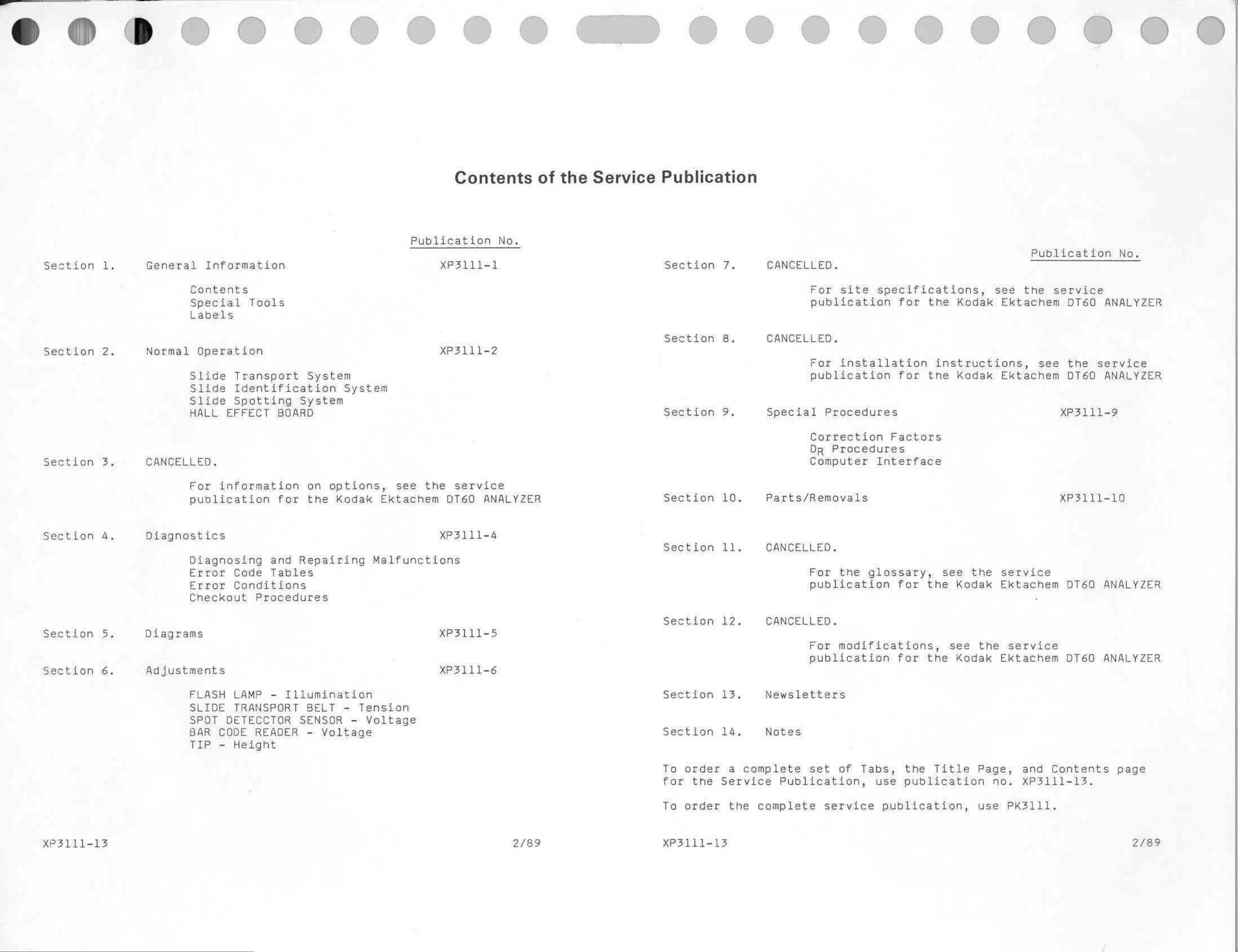
Contents
of
the
Service
Publication
Section
Section
General
Normal
Information
Contents
Special
Labels
Operation
Slide
Slide
Slide
Transport
Identification
Spotting
Tools
System
System
System
Publication
XP3111-1
XP3111-2
No.
Section
Section
7.
8.
CANCELLED.
For
publication
CANCELLED.
For
publication
site
installation
specifications,
for the
for
see
Kodak
instructions,
the
Kodak
Publication
the
Ektachem
see the
Ektachem
service
DT60
DT60
No.
ANALYZER
service
ANALYZER
Section
Section
HALL
CANCELLED.
For
publication
Diagnostics
Diagnosing
Error
EFFECT
information
and
Code
Tables
BOARD
for
Repairing
on
the
options,
Kedak
see
Ektachem
Malfunctions
the
service
DT60
XP3111-4
ANALYZER
Section
Section
Section
9.
10.
11.
Special
Parts/Removals
CANCELLED.
Procedures
Correction
DR
Computer
For
Procedures
the
Factors
Interface
glossary,
see
the
XP3111-9
XP3111-19
service
Section
Section
Error
Checkout
Diagrams XP3111-5
Adjustments
FLASH
SLIDE
SPOT
BAR
TIP
Conditions
Procedures
LAMP
TRANSPORT
DETECCTOR
CODE
-
Height
READER
-
Illumination
BELT
SENSOR
-
-
Tension
-
Voltage
XP3111-6
Voltage
Section
Section
Section
12.
13.
14.
publication
CANCELLED.
For
publication
Newsletters
Notes
for the
modifications,
for the
Kodak
see the
Kodak
Ektachem
service
Ektachem
DT60
DT60
ANALYZER
ANALYZER
XP3111-13
2/89
To
for
To
XP3111-13
order
the
order
a
complete
Service
the
complete
set
Publication,
of
service
Tabs,
use
publication,
the
publication
Title
Page,
no.
use
and
XP3111-13.
PK3111.
Contents
page
2/89
Page 4
Publication
No.
XP3111-1
4/86
Kodak
DTSC
General
Ektachem
MODULE
Information
The
information
Company
No patent
Eastman
with
resulting
prior
license
Kodak
respect
from
Section
contained
to
publication
is
granted
Company
to
this
information.
the
use
herein
reserves
of
this
is
based
by
this
tha
Kodak
information.
on
the
exparience
information
right
to
change
shall
not
be
even
if
loss
PLEASE
and
this
information
lisble
for
or
damage
NOTE
knowiedge
any
is
relating
without
loss
or
caused
notice.
by
Kodak's
to
the
subject
and
makes
damage.
including
negligence
1
matter
no
consequential
gained
warranty.
or
other
by
Eastman
express
or
special
fault
or
damages.
Kodak
implied,
©
Eastman
Kodak
Company,
1986
Page 5
Table
of
Contents
Figure
No.
Contents
Configuration
Special
of
Tools
the
of
Service
the
DTSC
Publication......,.............sssese
MODULE..............
sn
ne
al
2-9
XP3111-1,
4/86
~
Page 6
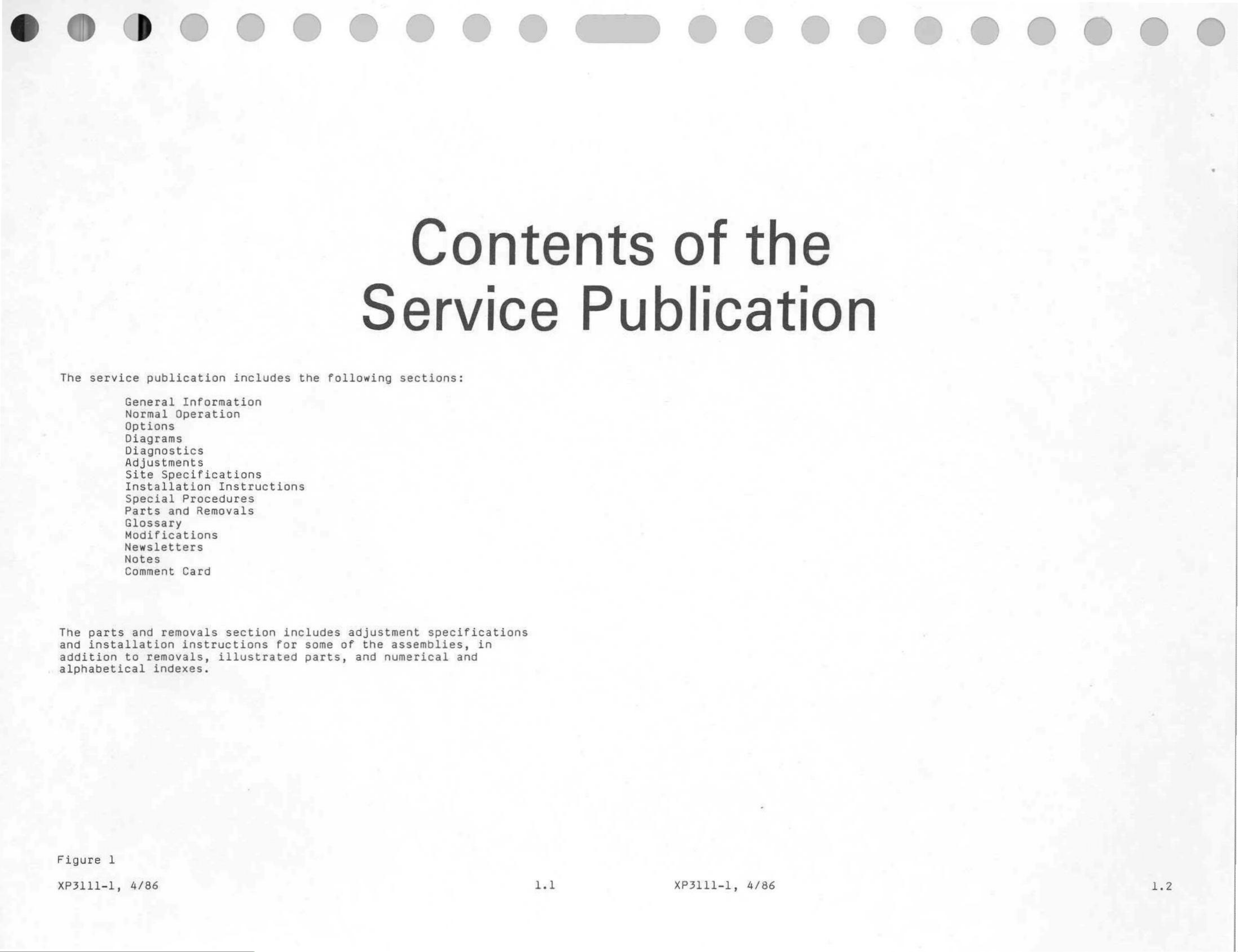
Contents
of
the
The
service
General
Normal
Options
Diagrams
Diagnostics
Adjustments
Site
Installation
publication
Information
Operation
Specifications
includes
Instructions
the
Service
following
Publication
sections:
The
and
addition
parts
installation
Special
Parts
Glossary
Modifications
Newsletters
Notes
Comment
and
to
removals
removals,
Procedures
and
Removals
Card
instructions
section
illustrated
includes
for
some
parts,
adjustment
of
the
and
specifications
assemblies,
numerical
and
alphabetical
indexes.
Figure
XP3111-1,
1
4/86
XP3111-1,
4/86
1.2
Page 7
READ
ARM AND
PREHEAT
HEATER
ARM AND
ASSEMBLY
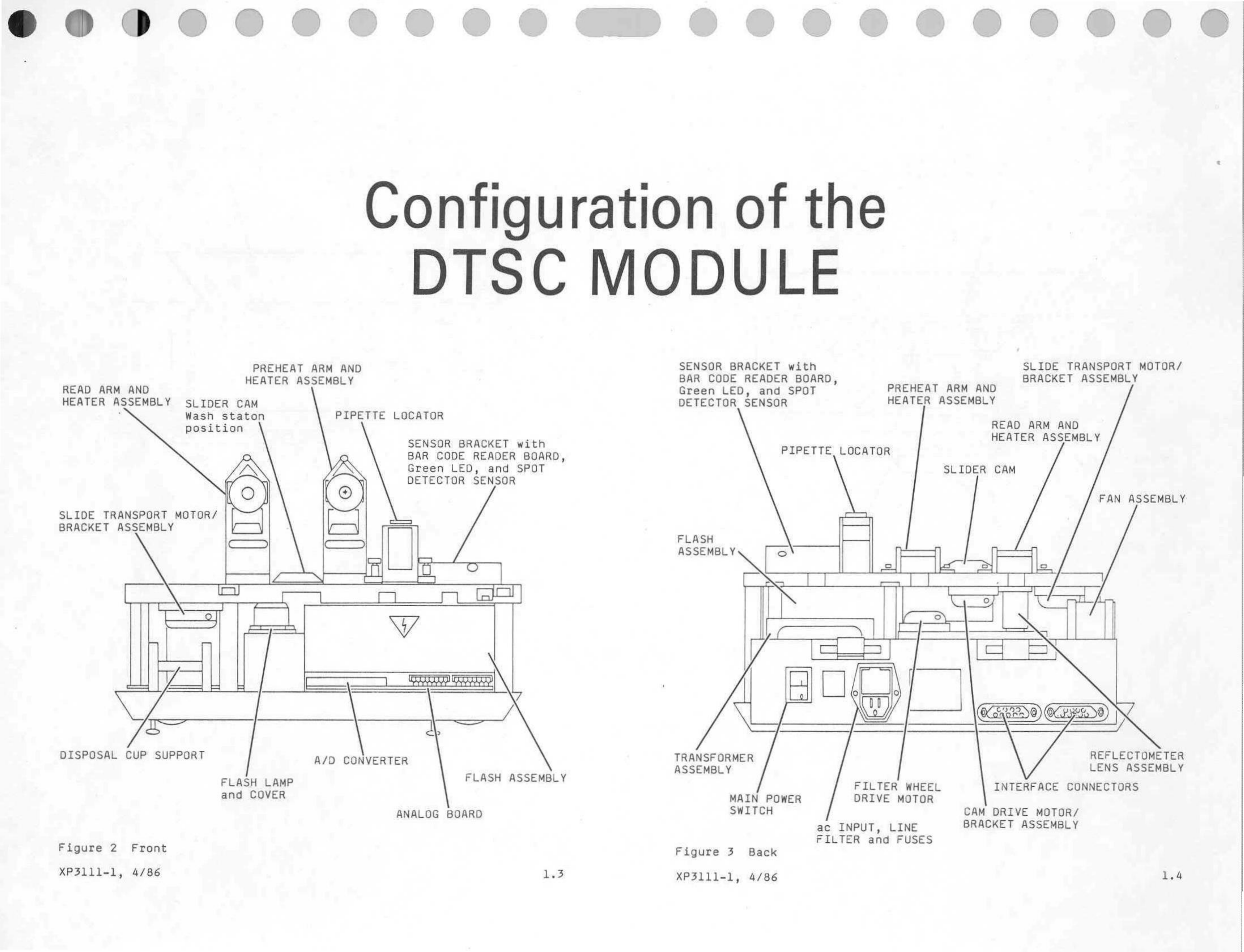
Configuration
DTSC
MODULE
SENSOR
BAR
Green
CODE
of
BRACKET
READER
LED,
and
the
with
BOARD,
SPOT
PREHEAT
ARM
AND
SLIDE
BRACKET
TRANSPORT
ASSEMBLY
MOTOR/
HEATER
SLIDE
BRACKET
ASSEMBLY
TRANSPORT
ASSEMBLY
SLIDER
Wash
position
MOTOR/
CAM
staton
PIPETTE
LOCATOR
SENSOR
BAR
Green
DETECTOR
BRACKET
CODE
LED,
READER
and
SENSOR
with
BOARD,
SPOT
DETECTOR
FLASH
ASSEMBLY
SENSOR
A
o
PIPETTE,
LOCATOR
HEATER
ASSEMBLY
SLIDER
READ
HEATER
CAM
ARM AND
ASSEMBLY
FAN
ASSEMBLY
Ns
|
(
I
[
TOM
Lol
Y
=
)
9
2
으
一
č
5
一
더
-
で
ちち
DISPOSAL
Figure
XP3111-1,
2
CUP
Front
4/86
SUPPORT
FLASH
and
COVER
LAMP
A/D
CONVERTER
ANALOG
FLASH
BOARD
ASSEMBLY
LZ
TRANSFORMER
ASSEMBLY
MAIN
SWITCH
Figure
XP3111-1,
3
Back
4/86
POWER
FILTER
WHEEL
INTERFACE
ac
FILTER
INPUT,
DRIVE
and
MOTOR
LINE
FUSES
CAM
BRACKET
DRIVE
MOTOR/
ASSEMBLY
REFLECTOMETER
LENS
CONNECTORS
ASSEMBLY
Page 8
READ
ARM
AND
PIPETTE LOCATOR
BAR
CODE
READER
BOARD
TRACK
SUBASSEMBLY
LINE
FILTER
FAN
ASSEMBLY
HEATER
ASSEMBLY
PIPETTE
LOCATOR
TRACK
FLASH
TRIGGER
SUBASSEMBLY
LAMP
MODULE
and
ANALOG
Figure
XP3111-1,
BOARD
4
RIBBON
Right
4/86
CABLE
side
CONNECTOR
TRANSFORMER
MAIN
ASSEMBLY
POWER
SWITCH
1.5
SLIDE
BRACKET
Figure
XP3111-1,
TRANSPORT
ASSEMBLY
5
Left
4/86
MOTOR/
side
ANALOG
MOTOR
BOARD
CONNECTORS
and
REFLECTOMETER
LENS
ASSEMBLY
1.6
>DO0
@
Page 9
0000009090
COMME
Net
CONNECTOR
CAM
DRIVE
CONNECTOR
READ
and
ARM
THERMISTOR
TOR
-
J12
MOTOR
CONNECTOR
LOWER
PLATEN
J2
HEATER
HEATER
«QE
33
CONNECTOR
FILTER
J4
WHEEL
MOTOR
CONNECTOR
PREHEAT
and
J5
ARM
THERMISTOR
CONNECTOR
SPOT
DETECTOR
SENSOR
CONNECTOR
BAR
BOARD
CONNECTOR
HEATER
J6
CODE
37
READER
38
LED
PIPETTE
DISPLAY
LED
PIPETTE
RECEIVER
DISPLAY
DS1
DS2
TRANSMITTER
TEST
A/D
POINT
SIGNAL
TP2
INPUT
TEST
BAR
POINT
CODE
TP3
INPUT
TEST
A/D
POINT
REFERENCE
TPL
CONNECTOR
SLTDE
MOTOR
TRANSPORT
Oo:
J11
È
DI
Ti
CONNECTOR
HALL-EFFECT
+
т
AL
me
J10
SENSOR
Reo
BOARD
CONNECTOR
RIBBON
CABLE
J9
ASSEMBLY
LED
COVER
TEST
ANALOG
TEST
REFERENCE
PHOTODIODE
OUTPUT
DISPLAY
POINT
RETURN
OPEN
TP7
a
SAMPLE
OUTPUT
POINT
DS3
POINT
PHOTODIODE
TP4
TP5
LED
A/D
DISPLAY
END
LED
SPOT
OF
DISPLAY
PRESENT
LED
SLIDE
DS4
CONVERT
DS5
DISPLAY
PRESENT
DS6
LED
BAR
a
TEST
VOLTAGE
SET
LED
FILTER
PHASE
DISPLAY
CODE
DISPLAY
POINT
DETECTOR
VOLTAGE
WHEEL
A
DS7
TP6
DS8
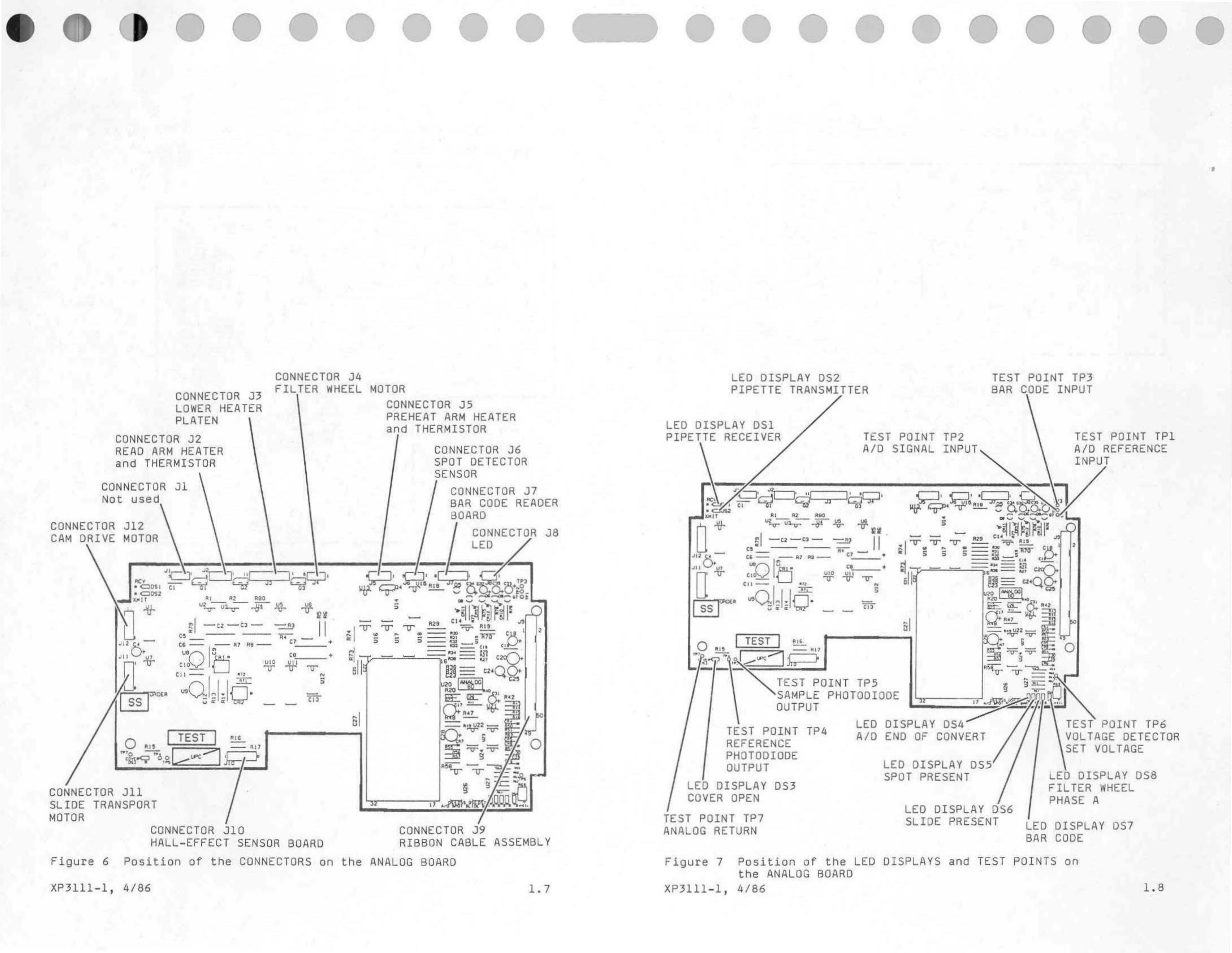
Figure
XP3111-1,
6
Position
4/86
of
the
CONNECTORS
on
the
ANALOG
BOARD
1.7
Figure
XP3111-1,
7
Position
the
4/86
ANALOG
of
BOARD
the LED
DISPLAYS
and
TEST
POINTS
on
1.8
Page 10
CONNECTOR
J2
TEST
POINT
TP3
CONNECTOR
SERIAL
Jl
INTERFACE
SERIAL
INTERFACE
CONNECTOR
FLASH
POWER
CONNECTOR
TRANSFORMER
J4
SUPPLY
J5
LED
DATA
LED
RECEIVE/TRANSMIT
DATA
DISPLAY
TRANSFER
DISPLAY
DS2
DS1
+12
Y
de
TEST
DIGITAL
POINT
TP4
GROUND
TEST
+15
POINT
V
de
TEST
-
15
TP5
POINT
V
de
TP6
CONNECTOR
FAN
ASSEMBLY
J6
ASSEMBLY
TEST
UNFILTERED
into
REGULATOR
TEST
+5
V
POINT
+12
POINT
de
V
TPE
de
de
TPZ
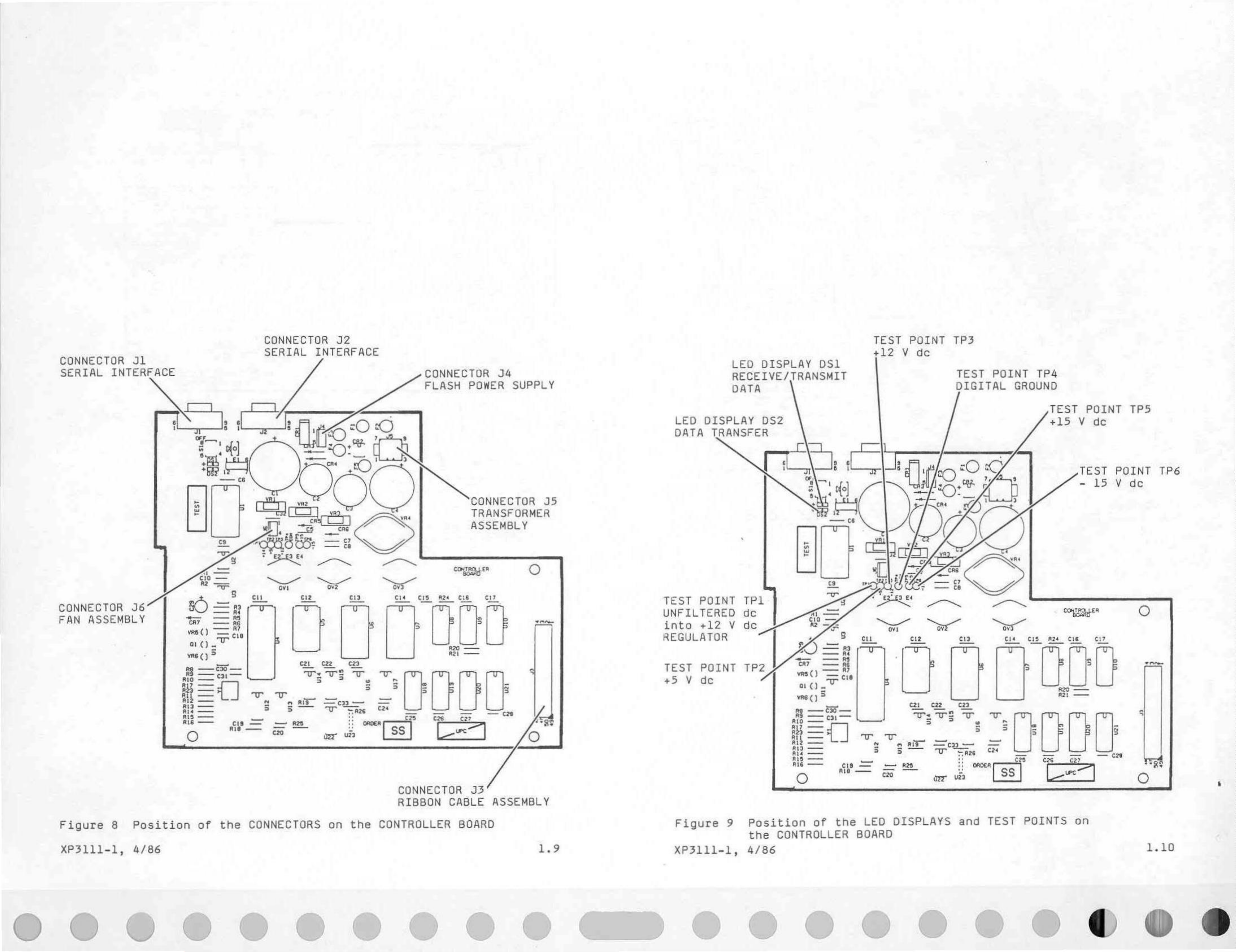
Figure
XP3111-1,
8
Position
4/86
of
the
CONNECTORS
on
the
CONNECTOR
RIBBON
CONTROLLER
J3
CABLE
BOARD
ASSEMBLY
1.9
Figure
XP3111-1,
9
Position
the
4/86
CONTROLLER
of
the
LED
BOARD
DISPLAYS
and
TEST
POINTS
on
1.10
O
©
©
Ч
)
W
L
|
>
tk
Page 11
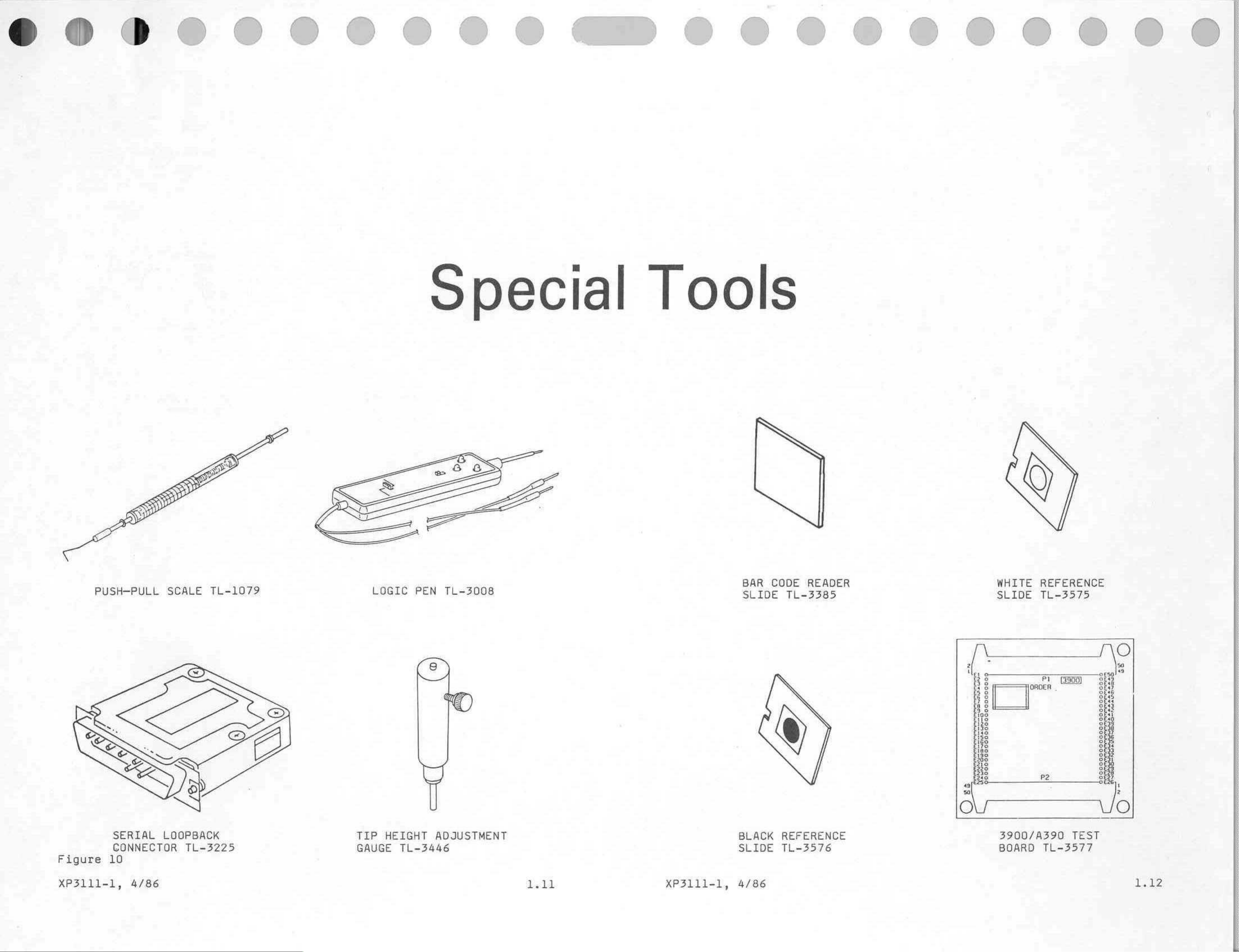
q
PUSH-PULL
SCALE
TL-1079
LOGIC
PEN
TL-3008
BAR
SLIDE
CODE
as
READE!
WHITE
SLIDE
REFERENCE
TL-3575
SERIAL
CONNECTOR
Figure
XP3111-1,
10
4/86
LOOPBACK
TL-3225
TIP
GAUGE
HEIGHT
TL-3446
ADJUSTMENT
1.11
XP3111-1,
BLACK
SLIDE
4/86
REFERENCE
TL-3576
3900/A390
BOARD
TL-3577
TEST
1.12
Page 12
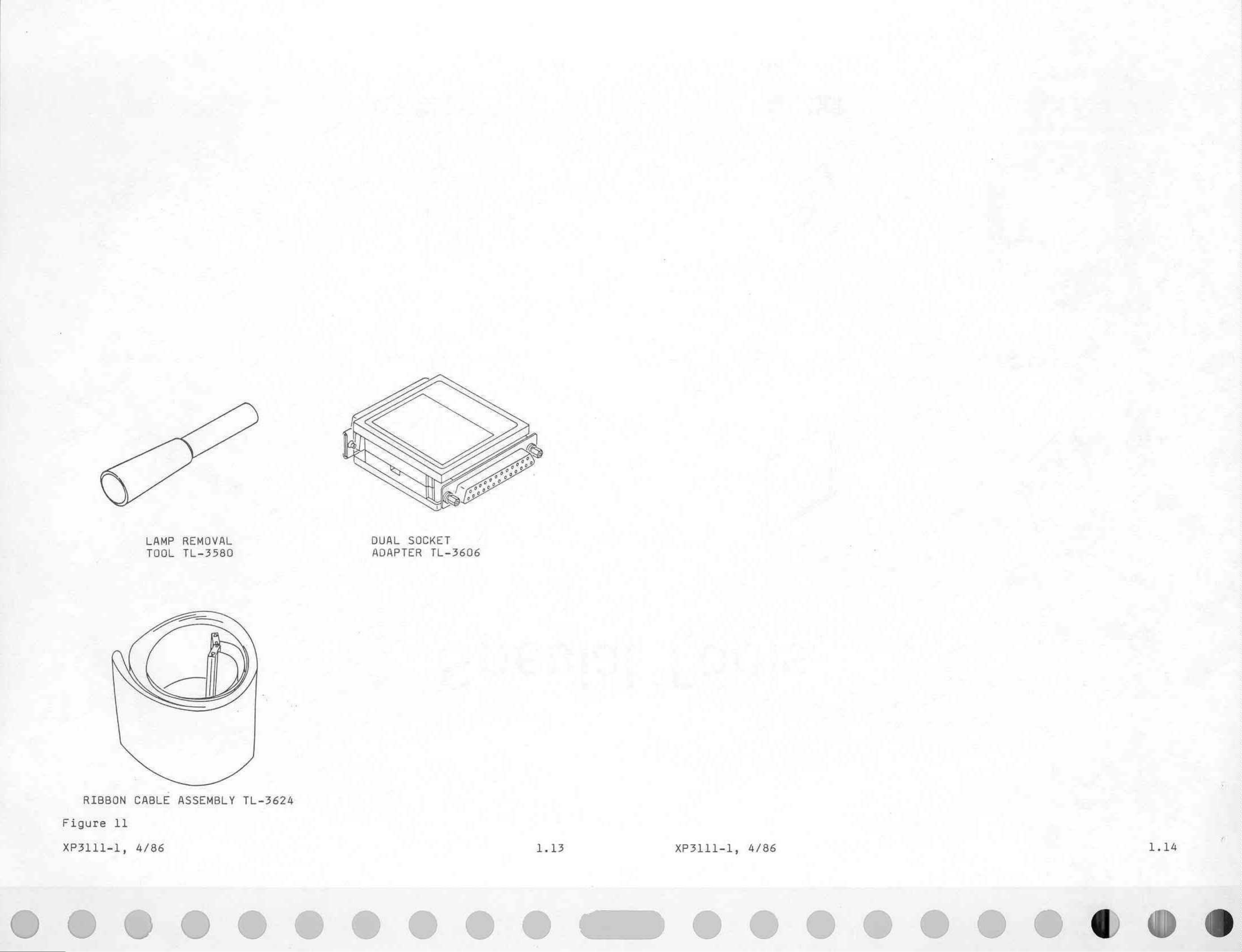
LAMP
REMOVAL
DUAL
SOCKET
TOOL
SIE
TL-3580 ADAPTER
TL-3606
RIBBON
Figure
XP3111-1,
11
CABLE
4/86
0000090
ASSEMBLY
TL-3624
1.13
|
XP3111-1,
4/86 1.14
0292900060
Page 13
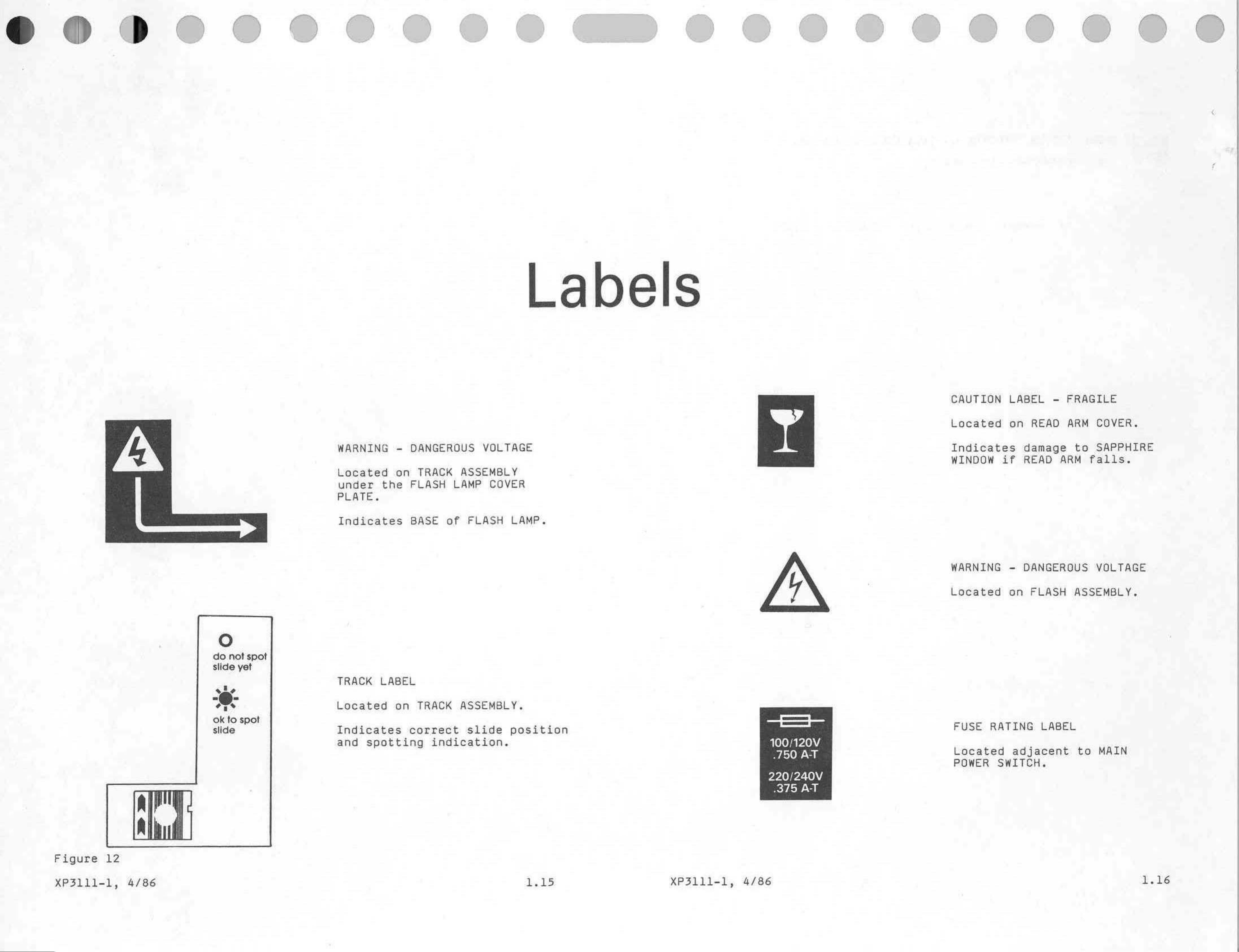
Labels
WARNING
Located
under
PLATE.
Indicates
the
-
DANGEROUS
on
TRACK
FLASH
BASE
ASSEMBLY
LAMP
of
FLASH
VOLTAGE
COVER
LAMP.
CAUTION
Located
Indicates
WINDOW
LABEL
on
if
-
READ
damage
READ
FRAGILE
ARM
to
ARM
falls.
COVER.
SAPPHIRE
o
do
not
slide
ok
to
slide
spot
yet
spot
TRACK
Located
Indicates
and
LABEL
spotting
on
TRACK
correct
ASSEMBLY.
slide
indication.
position
==
100/120V
-750
AT
WARNING
Located
FUSE
Located
POWER
RATING
-
DANGEROUS
on
adjacent
SWITCH.
FLASH
LABEL
VOLTAGE
ASSEMBLY.
to
MAIN
Figure
XP3111-1,
12
4/86
1,15
XP3111-1,
4/86
220/240V
„375
AT
1.16
Page 14
Kodak,
Ektachem,
and
DTSC
are
trademarks.
4/86
XP3111-1
EASTMAN
KODAK
COMPANY
Customer
©
ROCHESTER,
Equipment
Services
N.Y.
Division
14650
Printed
in
USA
Page 15
Publication
No.
XP3111-2
3/86
Slide
Slide
Slide
HALL
Kodak
Ektachem
Normal
Transport
Identification
Spotting
EFFECT
System....................
System..............
System......................
SENSORS.....................
DTSC
Section
Operation
Index
MODULE
2
Page
2.01
2.14
2.19
2.23
ANALOG
Temperature
Flash
Slide
Reading
Power
Initialization
The
information
gained
by
Eastman
No patent
Eastman
warranty,
including
is
license
Kodak
express
cohsequential
caused
by
Kodak's
and
CONTROLLER
Control
System
and
Light
Distribution
contained
Company
or
herein
Kodak
Company
is
granted
by
reserves
implied.
with
or
special
negligence
is
based
prior
this
information.
the right
respect
damages,
or
other
Path
*
To
be
PLEASE
NOTE
on
the
experience
to
publication.
to
change
to
this
information.
resulting
from
fault.
BOARD
provided
and
knowledge
this
information
Kodak
shall
the
use
of
in a revision.
relating
to
without
notice,
not
be
liable
for
this
information,
even
*
*
*
=
*
品
the
subject
and
any
loss
if
loss
matter
makes
or
damage,
or
damage
no
©
Eastman
Kodak
Company,
1986
Page 16
tion
2.
N
|
ration
+
Slide
Transport
tem
The
Slide
chemistry
Many
is
MODULE.
the
Slide
The
operations
only
a
operations
Stations
following
ㆍ
Pickup
first
allows
*
Hold
READER.
Transport
be
to
tests
occur
general
detected
Station.
description
The
following
that
7
stations
Station.
by
the
slide
The
System
processed.
occur
The
the
to
As
slide
moves
when
sections
at
are
defined
operator
BAR
be
inserted
the
slide
is
identified
Slide
the
of
each
CODE
moves
Transport
the
slide
the
motion
will
station.
for
manually
READER
and
Function
slides
to
the
moves
provide
through
of
the
Components
service
removed
to
when
inserts
the
Hold
it
purposes:
at
easily.
waits
System
correct
slide
more
the
this
Station,
stations
the
through
detailed
slide
station.
the
at
the
Hold
at
slide
path.
the
information
at
this
station.
A
SLIDE
bar
code
Station.
the
correct
This
DTSC
RECOVERY
is
read
times
section
about
An
inserted
by
the
to
allow
slide
WELL
BAR
the
is
CODE
+
Spotting
«
Preheat
+
Wash
*
Read
*
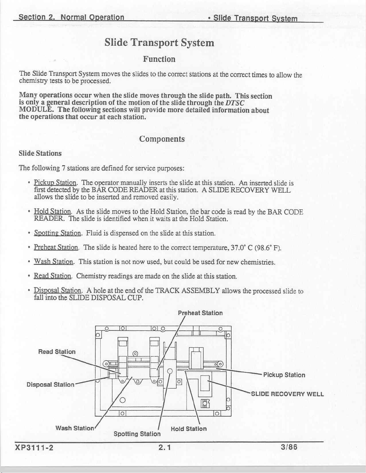
Disposal
Station.
Station.
Disposal
fall
into
Read
Station
Station.
Station.
Station. A hole
the
Station
Fluid
The
This
Chemistry
SLIDE
DISPOSAL
station
İLE
—
İİ
{AOE
is
dispensed
slide
is
readings
at
AAN
heated
is
not
the
end
CUP.
fT
0
here
now
are
of
on
the
used,
made
the
slide
to
the
but
on
TRACK
|
le
[e
at
this
correct
could
the
temperature,
be
slide
ASSEMBLY
Preheat
station.
used
for
at
this
station.
Station
-
EO)
[Pickup
Li
o]
37.0* C (98.6*
new
chemistries.
allows
the
ο]
의
|
|
—
sune
b
F).
processed
slide
RECOVERY
to
Station
WELL
XP3111-2
Wash
Station
Spotting
Station
2.1
Hold
Station
3/86
Page 17
i
rmal
ration
*
Slide
Transport
tem
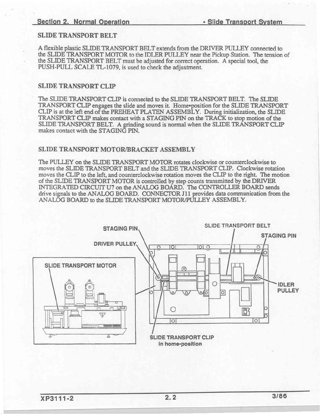
SLIDE
A
the
the
PUSH-PULL
SLIDE
The
TRANSPORT
CLIP
TRANSPORT
SLIDE
makes
SLIDE
The
moves
moves
of
INTEGRATED
drive
ANALOG
TRANSPORT
flexible
SLIDE
SLIDE
the
plastic
TRANSPORT
SLIDE
is
at
TRANSPORT
contact
TRANSPORT
PULLEY
the
the
SLIDE
signals
SLIDE
TRANSPORT
TRANSPORT
SCALE
TRANSPORT
CLIP
the
left
end
CLIP
with
the
on
the
SLIDE
CLIP
BOARD
TRANSPORT
to
the
TRANSPORT
CIRCUIT
to
the
ANALOG
to
BELT
TRANSPORT
MOTOR
BELT
TL-1079,
CLIP
CLIP
engages
of
the
PREHEAT
makes
SLIDE
contact
BELT. A grinding
STAGING
MOTOR/BRACKET
TRANSPORT
left,
and
MOTOR
U7
the
SLIDE
to
the
must
be
is
used
is
connected
the
slide
and
with a STAGING
PIN.
BELT
counterclockwise
is
on
the
ANALOG
BOARD.
TRANSPORT
BELT
to
PLATEN
and
extends
IDLER
adjusted
check
moves
sound
controlled
CONNECTOR
PULLEY
for
the
to
the
it.
ASSEMBLY.
is
normal
ASSEMBLY
MOTOR
the
SLIDE
rotation
BOARD.
MOTOR/PULLEY
from
the
DRIVER
near
the
correct
adjustment.
SLIDE
Homesposition
PIN
rotates
by
step
operation.
TRANSPORT
on
the
when
the
clockwise
TRANSPORT
moves
counts
The
CONTROLLER
J11
provides
PULLEY
Pickup
for
During
TRACK
SLIDE
the
CLIP
transmitted
ASSEMBLY.
Station.
A special
BELT.
the
SLIDE
initialization,
to
stop
TRANSPORT
or
counterclockwise
CLIP.
to
the
data
communication
connected
The
tool,
The
TRANSPORT
motion
Clockwise
right.
by
the
DRIVER
BOARD
tension
the
SLIDE
the
SLIDE
of
CLIP
to
rotation
The
motion
sends
from
to
of
the
the
SLIDE
TRANSPORT
DRIVER
MOTOR
A
©
>
STAGING
PULLEY,
PIN
LERİ
SLIDE
TRANSPORT
in
home-position
SLIDE
CLIP
TRANSPORT
i
BELT
STAGING
Ll
PIN
IDLER
PULLEY
XP3111-2
2.2
3/86
Page 18
tion
2.
Normal
ration
:
Sli
ran
t
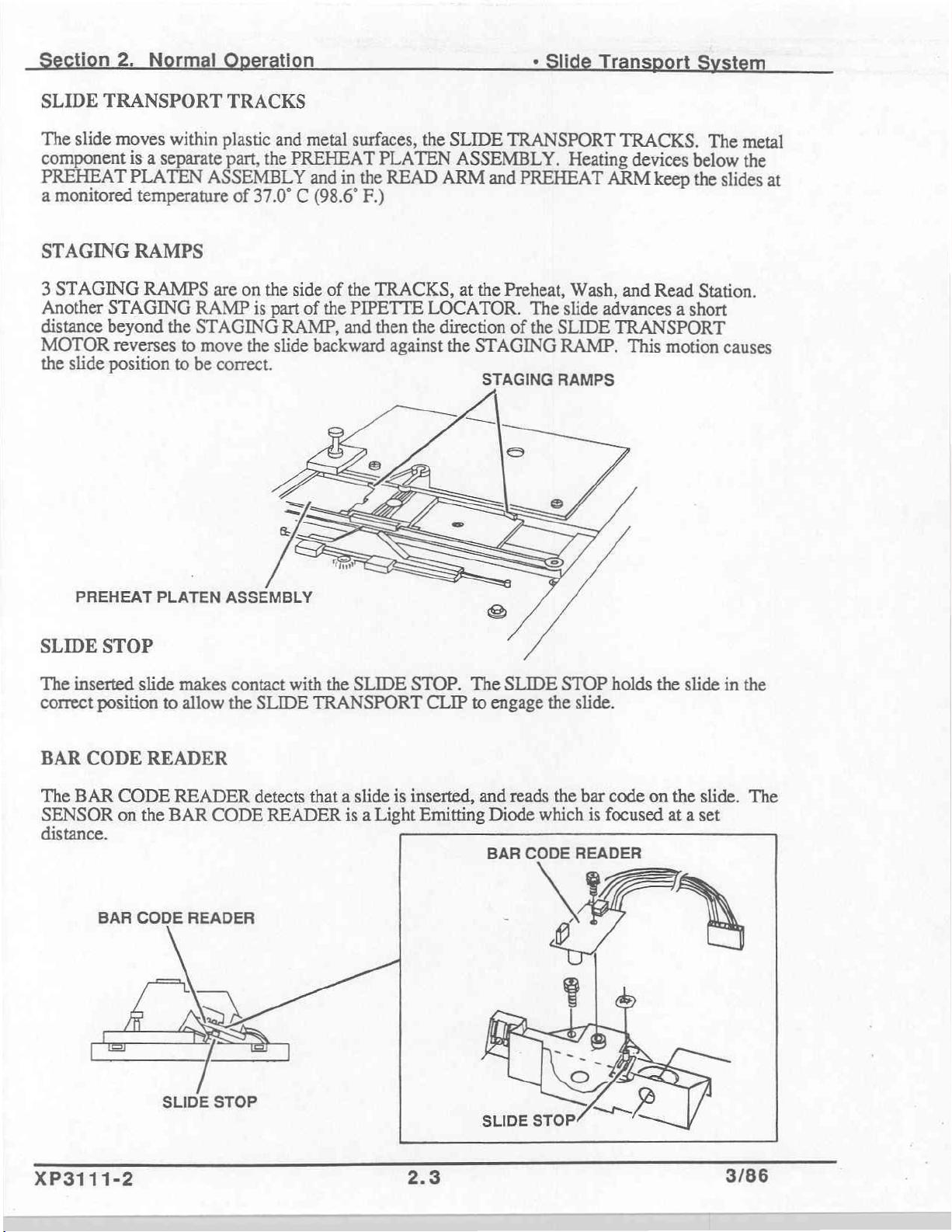
SLIDE
The
component
PREHEAT
a
monitored
STAGING
3
STAGING
Another
distance
MOTOR
the
TRANSPORT
slide
moves
STAGING
beyond
reverses
slide
position
within
is
a
separate
PLATEN
temperature
RAMPS
RAMPS
RAMP
the
STAGING
to
move
to
be
ASSEMBLY
TRACKS
plastic
part,
are
correct.
and
the
of
37.0° C (98.6°
on
the
is
part
RAMP,
the
slide
metal
PREHEAT
and
in
side
of
the
of
the
PIPETTE
and
backward
surfaces,
the
F.)
the
PLATEN
READ
TRACKS,
LOCATOR.
then
the
against
SLIDE
ASSEMBLY.
ARM
direction
the
and
at
the
STAGING
STAGING
TRANSPORT
PREHEAT
Preheat,
of
The
the
TRACKS.
Heating
Wash,
slide
SLIDE
RAMP.
RAMPS
devices
ARM
and
advances a short
TRANSPORT
This
keep
Read
motion
The
metal
below
the
the
slides
Station.
causes
at
PREHEAT
SLIDE
The
correct
BAR
The
SENSOR
distance.
STOP
inserted
position
CODE
BAR
CODE
on
BAR
PLATEN
slide
makes
to
READER
READER
the
BAR
CODE
allow
CODE
READER
ASSEMBLY
contact
the
with
SLIDE
detects
READER
the
SLIDE
TRANSPORT
that a slide
is a Light
STOP.
CLIP
is
inserted,
Emitting
The
to
engage
and
Diode
SLIDE
the
reads
which
STOP
slide.
the
holds
bar
code
is
focused
the
on
the
at a set
slide
in
slide.
the
The
XP3111-2
SLIDE
STOP
2.3
3/86
Page 19
n2
m
Ti
+
Slide
T
ri
t
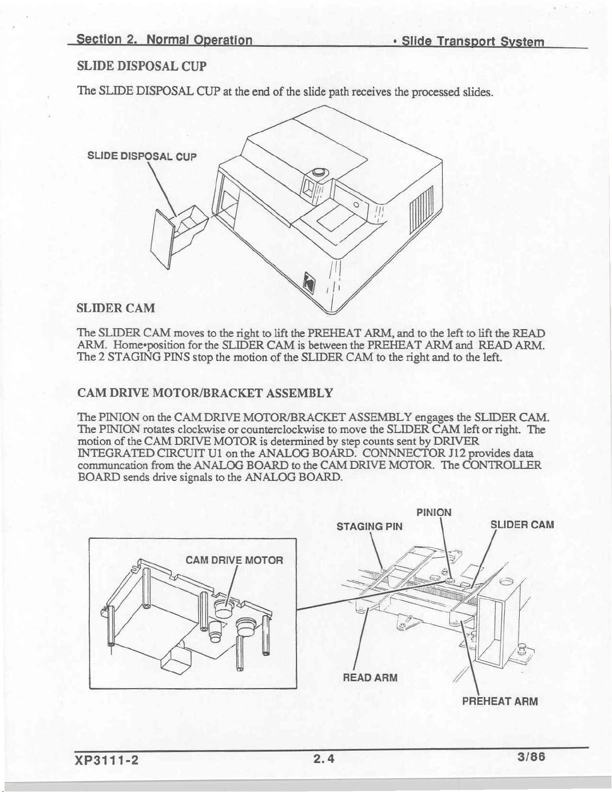
SLIDE
The
SLIDER
The
ARM.
The 2 STAGING
DISPOSAL
SLIDE
SLIDE
DISPOSAL
DISPOSAL
CAM
SLIDER
Home+position
CAM
CUP
CUP
moves
PINS
CUP
to
the
for the
stop
the
at
the
end
right
SLIDER
motion
of
to
CAM
of
the
lift
the
the
slide
PREHEAT
is
between
SLIDER
path
the
CAM
receives
the
ARM,
and
PREHEAT
to
the
processed
to
the
left
ARM
right
and
slides.
to
lift
and
READ
to
the
the
left.
READ
ARM.
CAM
The
The
motion
INTEGRATED
communcation
BOARD
DRIVE
PINION
PINION
of
the
sends
on
rotates
CAM
——
MOTOR/BRACKET
the
CAM
DRIVE
clockwise
DRIVE
CIRCUIT
from
the
drive
signals
U1
ANALOG
CAM
DRIVE
MOTOR
on
to
ASSEMBLY
MOTOR/BRACKET
or
counterclockwise
is
determined
the
ANALOG
the
BOARD
ANALOG
MOTOR
to
the
BOARD.
to
move
by
step
BOARD.
CAM
STAGING
READ
ASSEMBLY
the
SLIDER
counts
CONNNECTOR
DRIVE
MOTOR.
PIN
ARM
engages
sent
PINION
CAM
by
DRIVER
the
SLIDER
left
J12
provides
The
CONTROLLER
PREHEAT
or
right.
SLIDER
CAM.
The
data
CAM
ARM
XP3111-2
2.4
3/86
Page 20
Section
2.
Normal
Operation
*
Slide
Transport
System
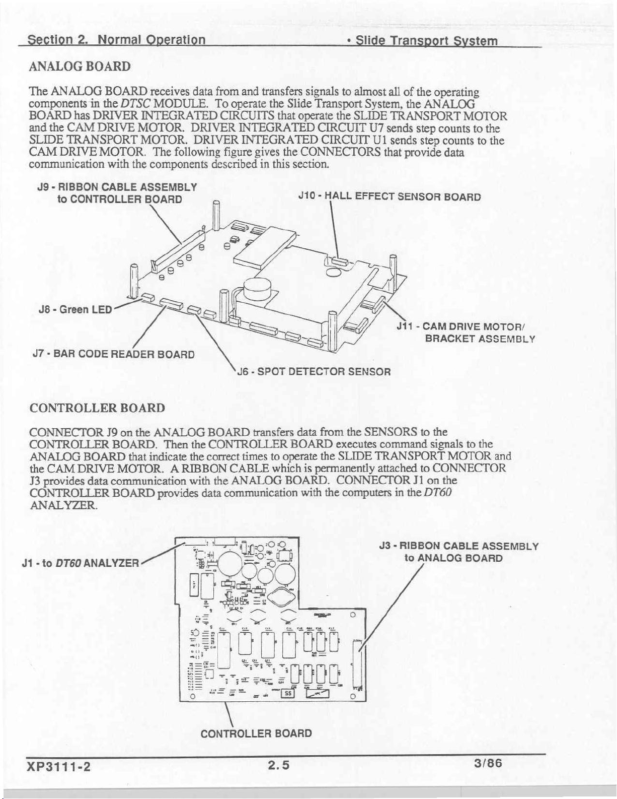
ANALOG
The
ANALOG
components
BOARD
and
the
SLIDE
CAM
communication
J9 - RIBBON
BOARD
in
has
DRIVER
CAM
TRANSPORT
DRIVE
to
DRIVE
MOTOR.
CONTROLLER
BOARD
the
CABLE
J8-GreenLED
47 - BAR
CODE
DTSC
with
receives
MODULE.
INTEGRATED
MOTOR.
MOTOR.
The following
the
components
ASSEMBLY
BOARD
data
from
To
CIRCUITS
DRIVER
DRIVER
figure
described
operate
D
y
READER
BOARD
and
transfers
the
Slide
that
INTEGRATED
INTEGRATED
gives
the
in
this
section.
J6 - SPOT
DETECTOR
signals
operate
CONNECTORS
J10 - HALL
to
almost
Transport
the
SLIDE
CIRCUIT
CIRCUIT
SENSOR
System,
U7
U1
EFFECT
all
of
the
the
TRANSPORT
sends
step
sends
step
that
provide
SENSOR
J11 - CAM
operating
ANALOG
counts
counts
data
BOARD
DRIVE
BRACKET
MOTOR
to
to
MOTOR/
ASSEMBLY
the
the
CONTROLLER
CONNECTOR
CONTROLLER
ANALOG
the
CAM
J3
provides
CONTROLLER
ANALYZER.
J1
-to
DT60
BOARD
DRIVE
data
BOARD
J9
on
the
ANALOG
BOARD.
that
MOTOR.
communication
BOARD
Then
indicate
A
provides
ο,
BOARD
the
CONTROLLER
the
correct
RIBBON
with
the
data
:
transfers
times
CABLE
ANALOG
communication
data
BOARD
to
operate
which
BOARD.
with
from
the
executes
the
SLIDE
is
permanently
CONNECTOR
the
computers
SENSORS
command
TRANSPORT
attached
in
the
J3 - RIBBON
to
to
the
signals
to
CONNECTOR
J1
on
the
DT60
CABLE
ANALOG
to
MOTOR
BOARD
the
and
ASSEMBLY
XP3111-2
CONTROLLER
BOARD
2.5
3/86
Page 21
n
2.
|
tion
e
Sli
n:
ti
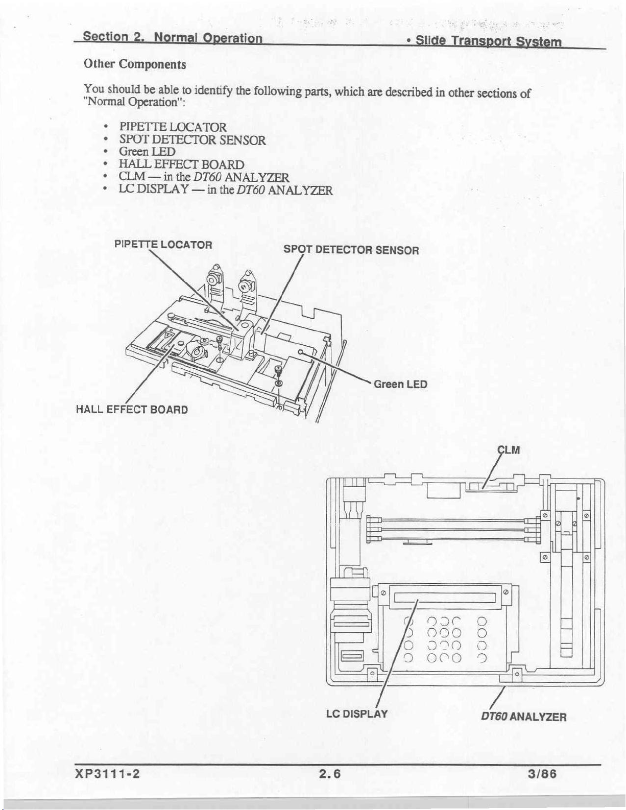
Other
You
"Normal
Components
should
PIPETTE
SPOT
Green
HALL
CLM — in
“ec...
LC
PIPETTE
be
able
to
Operation":
LOCATOR
DETECTOR
LED
EFFECT
the
DT60
DISPLAY
—
LOCATOR
identify
BOARD
in
the
SENSOR
ANALYZER
the
DT60
following
ANALYZER
parts,
SPOT
which
DETECTOR
are
described
SENSOR
in
other
sections
of
HALL
EFFECT
BOARD
XP3111-2
LC
2.6
DISPLAY
DT60
ANALYZER
3/86
Page 22
ti
rati
n
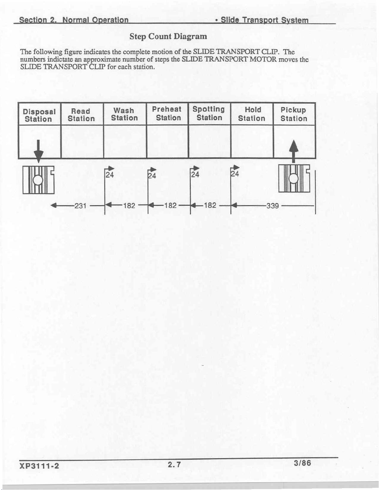
The
following
numbers
SLIDE
Disposal
Station
|
TRANSPORT
ῃ
figure
indictate
|
Station
자
indicates
an
approximate
CLIP
Read
231
the
complete
number
for
each
Wash
Station
=>
24
182
Step
Count
motion
of
station.
Preheat
Station
Ba
steps
the
182
Diagram
of
the
SLIDE
SLIDE
Spotting
|
Station
>
24
TRANSPORT
TRANSPORT
Station
[を
24
182
MOTOR
Hold
CLIP.
339
The
moves
Pickup
Station
le
the
|
XP3111-2
2.7
3/86
Page 23
ti
1.
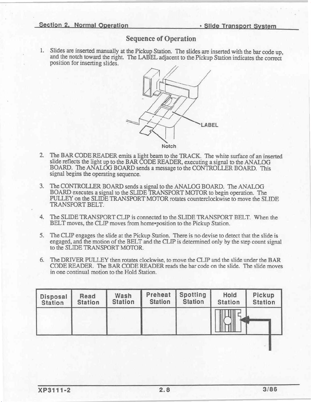
Slides
and
position
2.
The
slide
BOARD.
signal
are
inserted
the
notch
for
inserting
BAR
CODE
reflects
begins
the
The
manually
toward
READER
light
ANALOG
the
operating
i
at
the
right.
slides.
emits
up
to
the
BOARD
sequence.
Sequence
the
Pickup
The
LABEL
Station.
Operation
of
The
adjacent
slides
to
the
‧
are
inserted
Pickup
Station
rt
with
the
bar
indicates
the
m
code
up,
correct
AL
Notch
a
light
beam
to
the
BAR
CODE
sends
READER,
a
message
TRACK.
executing
the
to
The
white
a
signal
CONTROLLER
surface
to
the
ANALOG
BOARD.
of
an
inserted
This
3.
The
BOARD
PULLEY
TRANSPORT
4,
The
BELT
5.
The
engaged,
to
6.
The
CODE
in
Disposal
Station
CONTROLLER
executes a signal
on
SLIDE
CLIP
the
DRIVER
one
TRANSPORT
moves,
engages
and
SLIDE
READER.
continual
Read
Station
BOARD
the
SLIDE
BELT.
the
CLIP
the
slide
the
motion
TRANSPORT
PULLEY
The
BAR
motion
sends a signal
to
the
SLIDE
TRANSPORT
CLIP
is
moves
of
then
to
Wash
Station
from
at
the
the
BELT
MOTOR.
rotates
CODE
the
Hold
Pickup
to
the
TRANSPORT
MOTOR
connected
homesposition
Station.
and
the
clockwise,
READER
Station.
Preheat
Station
rotates
to
the
CLIP
to
reads
|
ANALOG
MOTOR
SLIDE
to
the
There
is
determined
move
the
Spotting
Station
BOARD.
counterclockwise
TRANSPORT
Pickup
is
no
devise
the
CLIP
bar
code
The
to
begin
operation.
Station.
to
detect
only
by
and
the
on
the
slide.
Hold
Station
li
ANALOG
to
move
BELT.
that
the
step
slide
the
When
the
count
under
The
slide
Pickup
Station
The
SLIDE
slide
signal
the
moves
the
is
BAR
XP3111-2
2.8
3/86
Page 24
tion
7.
The
transfers
8.
The
the
MODULE.
9.
For
decoded.
SELECT
2.
Normal
bar
code
the
bar
code
status
the
of
slide
If
TEST"
data
is
sent
data
to
the
data
is
the
chemistry.
to
be
successfully
the
bar
code
is
displayed.
ration
to
the
DT60
ANALYZER
compared
The
is
partially
CONTROLLER
with
data
stored
DT60
ANALYZER
identified
The
as a rate
decoded,
operator
BOARD.
for
identification.
in
the
CDM
then
slide,
at
the
message
must
manually
+
Slide
Transport
The
CONTROLLER
in
the
DT60
sends a response
least the
"SLIDE
select
ANALYZER
first 3 bars
NOT
IDENTIFIED
the
test
on
to
BOARD
the
DTSC
must
the
KEYBOARD.
to
be
tem
check
/
10.
Data
is
in
the
CLM.
calibrated
11.
Ifthe
chemistry
the
slide,
sends a message
Station.
12.
If
the
chemistry
ANALYZER
name
of
13.
The
slide
BELT
BELT
device
read
from
the
The
chemistry
for
the
generation
is
not
the
message
to
the
is
included
sends
all
the
chemistry
advances a short
reverses
is
determined
to
check
to
move
that
the slide
only
CLM
that
of
number
included
"SLIDE
DISC
in
data
necessary
is
displayed.
distance
the
slide
by
step
ЩИ
These 3 bars
checks
the
slide
of
in
the
NOT
MODULE
the
CLM
The
beyond
backward
count
is
in
the
=
identify
if
the
chemistry
must
exist
the
slide.
CLM,
IDENTIFIED"
correct
or
that
causes
and
is
for
processing
slide
the
against
to
the
SLIDE
position.
is
not
calibrated
advances
Spotting
rate
slides
of
the
in
the
CLM,
calibrated
is
displayed.
the
slide
for the
the
slide
to
the
Station,
the
STAGING
TRANSPORT
slide
is
compatible
and
the
for
the
The
to
be
returned
generation
to
the
DISC
Spotting
and
then
RAMP.
MOTOR,
with
chemistry
generation
DT60
number,
MODULE.
Station.
the
must
number
ANALYZER
to
the
Pickup
direction
The
motion
and
the
be
the
DT60
The
of
of
there
is
data
of
the
the
no
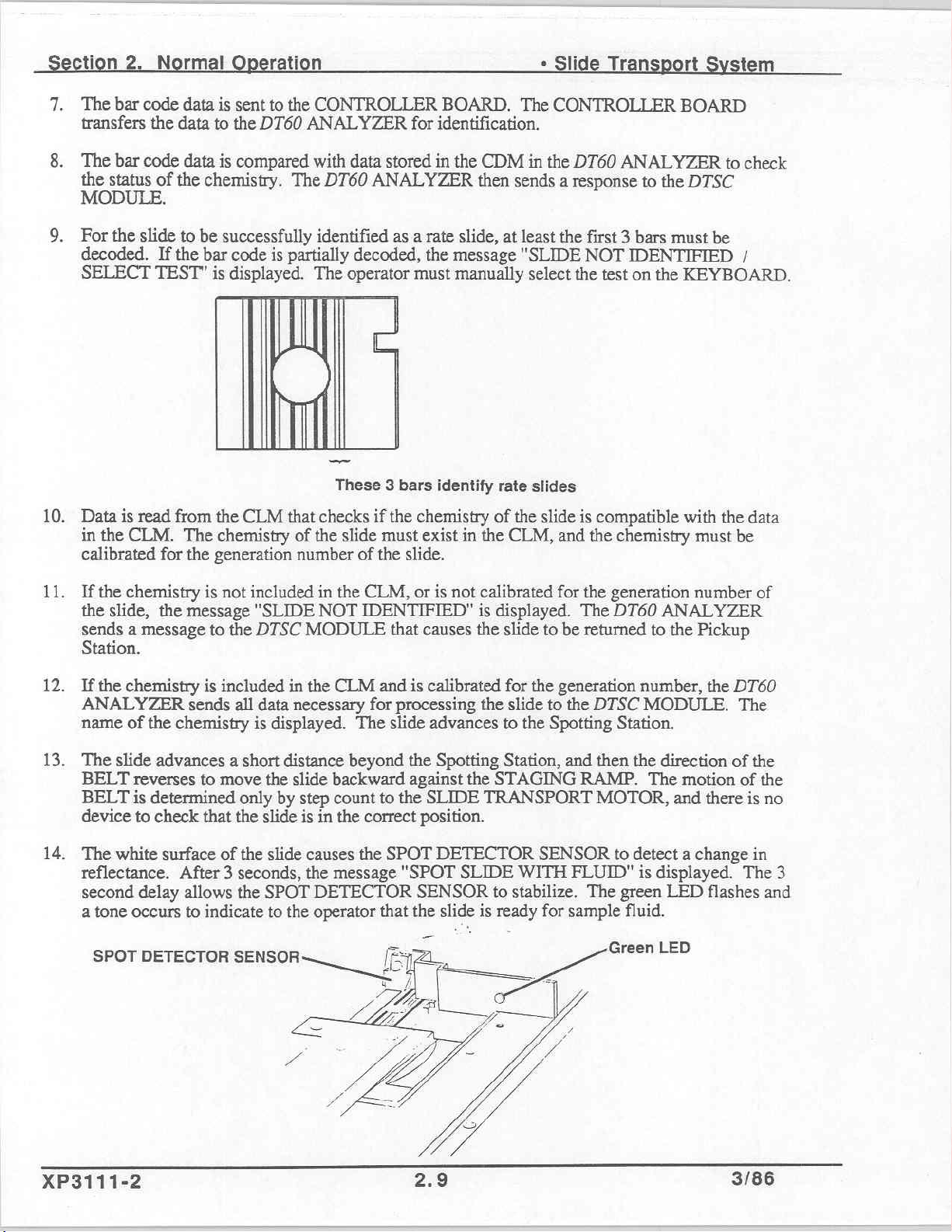
14.
The
white
surface
reflectance. After 3 seconds,
second
a
tone
SPOT
delay
occurs
DETECTOR
of
allows
to
indicate
XP3111-2
the
the
slide
SPOT
to
the
causes
the
the
message
DETECTOR
operator
Zz
SPOT
"SPOT
that
re
DETECTOR
SENSOR
the
slide
SLIDE
デン
WITH
to
stabilize.
is
ready
ディ
SENSOR
FLUID"
The
for
sample
to
detect a change
is
displayed.
green
Green
LED
fluid.
LED
in
The
3
flashes and
3786
Page 25
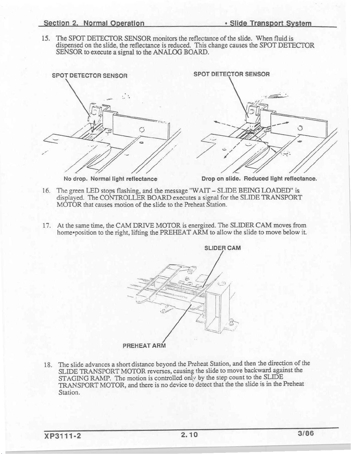
15.
tion
2.
The
SPOT
dispensed
SENSOR
N
rati
DETECTOR
on
the
slide,
the
to
execute a signal
SENSOR
reflectance
to
the
monitors
the
is
reduced.
ANALOG
reflectance
This
change
BOARD.
+
Slide
of
the
slide.
causes
Ti
When
the
SPOT
t t
fluid
is
DETECTOR
SPOT
16.
No
The
DETECTOR
green
displayed.
MOTOR
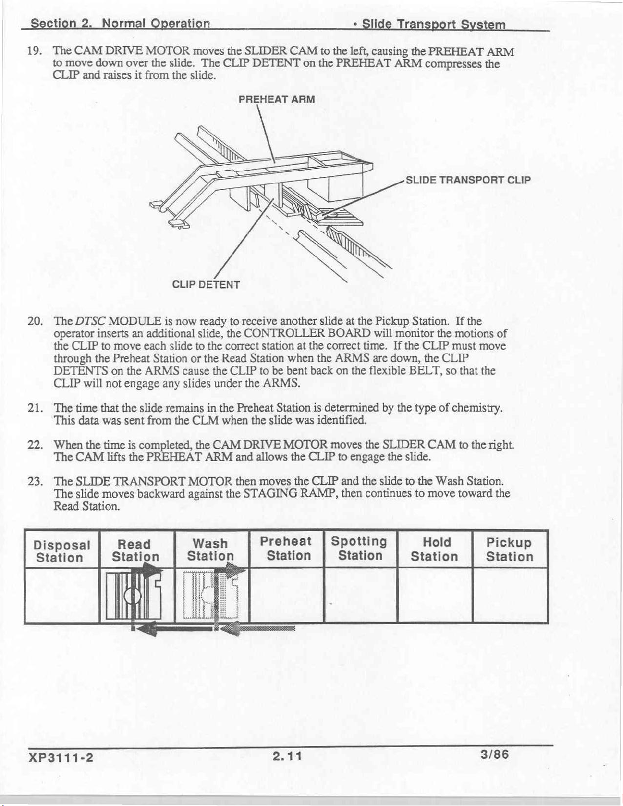
17.
Atthe
homesposition
drop.
LED
The
that
same
SENSOR
Normal
light
stops
CONTROLLER
causes
time,
the
to
the
reflectance
flashing,
motion
CAM
right,
and
of
DRIVE
lifting the
the
message
BOARD
the
slide
to
MOTOR
PREHEAT ARM
SPOT
DETECTOR
"WAIT — SLIDE
executes a signal
the
Preheat
is
energized.
for
Station.
The
to
allow
SENSOR
BEING
the
SLIDE
SLIDER
the
slide
LOADED"
TRANSPORT
CAM
to
moves
move
is
from
below
it.
18.
slide
The
SLIDE
TRANSPORT
STAGING
TRANSPORT
Station.
advances
a
RAMP.
MOTOR,
PREHEAT
short
MOTOR
motion
The
distance
reverses,
is
there
and
ARM
beyond
the
causing
controlled
device
no
is
Preheat
the
by
only
detect
to
SLIDER
Station,
to
slide
step
the
that
CAM
and
move
count
the
the
direction
:he
then
backward
SLIDE
the
to
in
is
slide
of
against
the
the
Preheat
the
XP3111-2
2.10
3/86
Page 26
19.
ti
The
CAM
to
move down
CLIP
and
Normal
DRIVE
over
raises
it
MOTOR
the
slide.
from
ration
moves
The
the
slide.
the
SLIDER
CLIP
DETENT
CAM
on
to
the
the
PREHEAT
left,
causing
ri
ARM
the
PREHEAT
compresses
tem
ARM
the
20.
The
DTSC
operator
the
through
DETENTS
CLIP
inserts
CLIP
the
will
MODULE
to
move
Preheat
on
the
not
engage
CLIP
is
now
an
additional
each
slide
Station
ARMS
any
DETENT
ready
slide,
to
the
or
the
cause
slides
PREHEAT
to
the
correct
Read
the
CLIP
under
ARM
receive
CONTROLLER
Station
the
another
station
to
ARMS.
be
at
when
bent
slide
BOARD
the
correct
the
back
at
ARMS
on
the
the
Pickup
will
time.
are
flexible
SLIDE
Station.
monitor
If
the
CLIP
down,
the
BELT,
TRANSPORT
If
the
the
motions
must
CLIP
so
that
CLIP
of
move
the
21.
The
This
22.
When
The
23.
The
The
Read
Disposal
Station
time
that
data
was
the
time
CAM
SLIDE
slide
lifts
TRANSPORT
moves
Station.
]|
Station
the
slide
sent
from
is
completed,
the
PREHEAT ARM
backward
Read
remains
the
CLM
the
MOTOR
against
Wash
Station
in
CAM
the
Preheat
when
and
then
the
Station
the
slide
DRIVE
STAGING
MOTOR
allows
moves
Preheat
Station
is
determined
was
identified.
the
CLIP
the
CLIP
RAMP,
|
by
moves
to
engage
and
then
the
the
SLIDER
the
slide
continues
Spotting
Station
the
type
slide.
to
the
to
Station
of
chemistry.
CAM
Wash
move
Hold
to
the
right.
Station.
toward
the
Pickup
Station
XP3111-2
2-11 3/86
Page 27
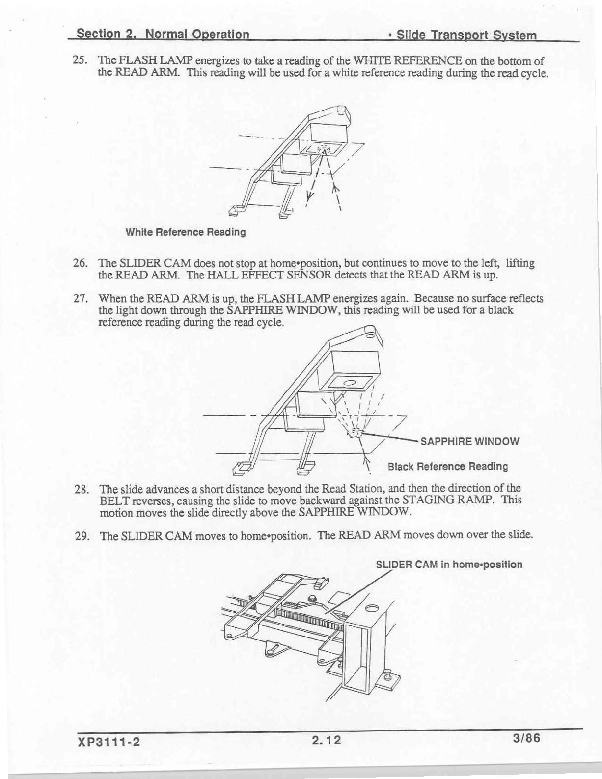
25.
tion
The
the
2
FLASH
READ
LAMP
ARM.
energizes
This
reading
to
take a reading
will
be
used
of
the
WHITE
for a white
+
Slide
REFERENCE
reference
reading
Tr
during
rt m
on
the
bottom
the
read
of
cycle.
26.
27.
28.
The
When
White
SLIDER
the
READ
the
READ
the
light
down
reference
The
BELT
motion
reading
slide
advances a short
reverses,
moves
Reference
CAM
ARM.
The
ARM
through
during
causing
the
Reading
does
HALL
is
the
slide
directly
not
stop
at
EFFECT
up, the
SAPPHIRE
the
read
FLASH
cycle.
77
distance
the slide
to
above
home+position,
SENSOR
LAMP
WINDOW,
but
detects
energizes
this
Ne
;
beyond
move
the
backward
the
SAPPHIRE
Read
continues
that
the
again.
reading
Wo
X
Station,
against
WINDOW.
7
\
7
。
—
Black
and
the
to
move
READ
Because
will
be
used
SAPPHIRE
Reference
then
the
STAGING
to
the
left,
ARM
is
up.
no
surface
for a black
WINDOW
Reading
direction
RAMP.
lifting
reflects
of
the
This
The
29.
XP3111-2
SLIDER
CAM
moves
home+position.
to
The
2.12
READ
ARM
SLIDER
moves
CAM
down
over
in
home-position
the
slide.
3/86
Page 28
Section
30.
The
HALL
the
Read
31.
The
data
identified.
number
32.
When
33.
The
SLIDER
HALL
34.
The
CLIP
The
CLIP
35.
At
the
moves
2.
Normal
Station,
for
of
the
reading
EFFECT
moves
is
same
down.
Operation
EFFECT
the
The
readings.
CAM
now
time,
SENSOR
error
number
FLASH
cycle
moves
SENSOR
the
slide
in
the
the
SLIDER
detects
code
F31
of
readings
POWER
is
completed,
left,
lifting
detects
to
the
that
occurs.
was
SUPPLY
the
the
that
the
Disposal
home+position.
CAM
moves
the
slide
sent
from
energizes
results
READ
READ
Station,
right,
だ
is
under
the
CLM
the
are
printed.
ARM.
ARM
and
the
to
the
だ
xsSlideTransportSvstem
the
READ
when
FLASH
The
CLIP
is
up.
slide
falls
home+position.
the
the
LAMP
engages
into
ARM.
BAR
for
the
the
The
If
no
CODE
the
necessary
slide.
DISPOSAL
READ
slide
was
The
CUP.
ARM
is
_
in
XP3111-2
2.13
3/86
Page 29
Norm
ti
«Slide
Identification
The
Slide
Identification
executes a signal
information
With
this
data,
chemistry,
MODULE
calibrated
+
the
・
the
+
the
in
the
the
that
is
time
filter
number
to
used
System
start
the
bar
code
on
CLM
in
the
for
the
to
determine
the slide
used
to
of
flash
should
read
Slide
operation
equipment.
readings
Identification
first
detects
sequence.
the
slide
DT60
ANALYZER
the
remain
the
slide
that
Function
that a slide
The
and
transfers
first
Then
the
DT60
following
in
must
Components
functions:
the
Preheat
be
made.
System
is
inserted
Slide
Identification
the
information
determines
ANALYZER
Station
into
to
if
the
the
Pickup
System
the
ANALOG
slide
sends
Station,
also
is
an
acceptable
data
to
and
decodes
BOARD.
the
DTSC
then
the
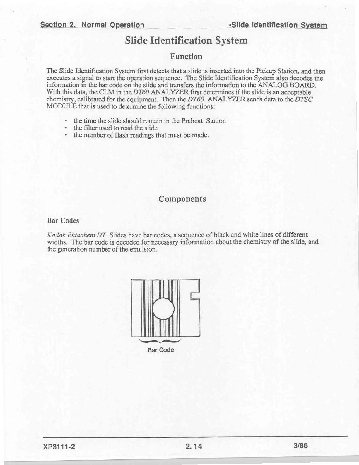
Bar
Codes
Kodak
widths.
the
Ektachem
generation
The
DT
bar
code
number
Slides
is
have
decoded
of
the
bar
codes, a sequence
for
necessary
emulsion.
Bar
Code
information
of
black
about
and
white
the
chemistry
lines
of
of
different
the
slide,
and
XP3111-2
2.14
3/86
Page 30
tion
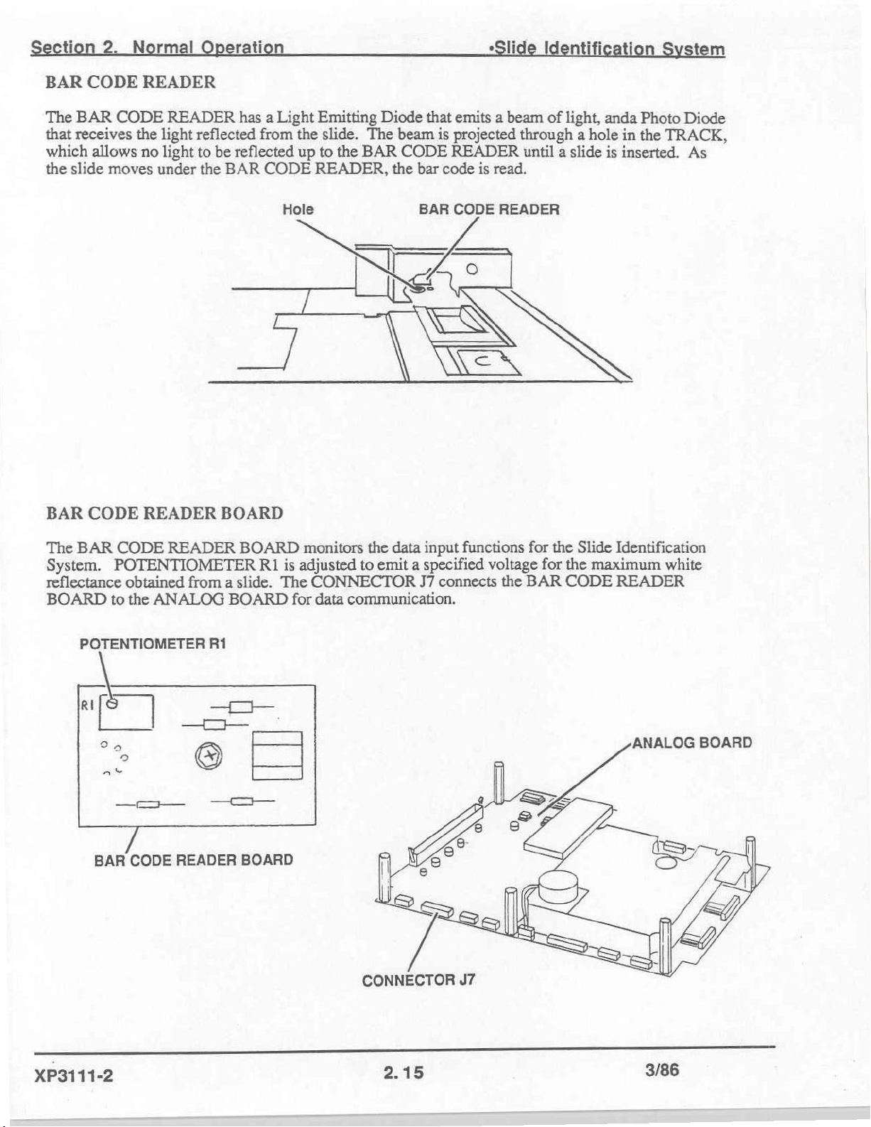
BAR
The
BAR
that
receives
which
the
slide
2.
CODE
CODE
allows
moves
Normal
READER
READER
the
light
no
light
under
rati “Sli
has a Light
reflected
to
be
the
from
reflected
BAR
CODE
Emitting
the
slide.
up
to
the
READER,
Diode
The
BAR
beam
CODE
the
that
is
bar
code
emits a beam
projected
READER
through a hole
until a slide
is
read.
of
light,
11
anda
in
is
inserted.
Photo
the
TRACK,
m
Diode
As
BAR
CODE
The
BAR
CODE
System.
reflectance
BOARD
POTENTIOMETER
obtained
to
the
READER
READER
from a slide.
ANALOG
BOARD
BOARD
Hole
BOARD
RI
monitors
is
adjusted
The
CONNECTOR
for
data
BAR
Ww
the
data
input
to
emit a specified
J7
connects
communication.
CODE
READER
functions
voltage
the
for
the
for the
BAR
Slide
maximum
CODE
Identification
white
READER
POTENTIOMETER
η
Sia;
aX
一
BAR
XP3111-2
CODE
R1
ーー
©
—=—
READER
BOARD
ANALOG
BOARD
CONNECTOR
2.15
J7
3/86
Page 31

tion
Norma
rati
*Slide
Identificati
tem
1.
When
the
2
The
signal
CONTROLLER
the
DTSC
TRACK.
white
surface
to
the
MODULE
The
hole
of
ANALOG
BOARD.
Sequence
allows
an
inserted
BOARD.
of
is
initialized,
almost
This
no
Hole
slide
reflects
The
ANALOG
signal
Operation
the
BAR
light
to
light
begins
the
CODE
be
reflected
BAR
CODE
to
the
BAR
BOARD
operation
READER
up
to
the
READER
CODE
sends
a
message
seguence.
projects
BAR
READER,
a
CODE
to
light
READER.
which
the
to
a
hole
causes
in
a
3.
4.
5.
6.
The
CONTROLLER
BOARD
The
SLIDE
to
the
Pickup
The
CLIP
As
the
slide
read.
sends a
signal
TRANSPORT
Station
moves
the
moves
BOARD
to
to
engage
slide
under
sends a signal
the
SLIDE
MOTOR
the
to
the
Hold
the
BAR
CODE
TRANSPORT
moves
slide.
Station,
READER,
to
the
the
SLIDE
in
ANALOG
MOTOR
one
continual
the light
BOARD.
to
begin
TRANSPORT
motion.
reflected
The
ANALOG
operation.
CLIP
from
from
the
bar
home+position
code
is
XP3111-2
2.16
3/86
Page 32

Section
7.
The
light
the
uniform
thickness
The
you
CODE
2.
Normal
BAR
CODE
reflected
black
following
understand
READER.
from
lines
do
negative
of
the
figure
Operation
READER
the
white
not.
The
electrical
lines.
is a graphic
these
fundamentals,
BOARD
and
adjustment
value
makes a series
black
to
the
description
you
lines
in
the
procedure
white
lines.
of a bar
will
be
of
bar
for the
The
code
able
to
“Slide
electrical
code.
BAR
length
understand
signals
The
CODE
of
conversion
Identification
that
correspond
white
lines
reflect
READER
the
signals
to
the
correspond
an
electrical
adjustment
light,
gives
signal.
for the
to
a
the
and
to
BAR
tem
the
If
8.
Because
READER
9.
The
The
DT60
10.
If
Station.
of
BAR
signal
ANALYZER.
no
bar
code
Readings
the
position
BOARD
CODE
is
transferred
READER
data
reverses
was
Voltage
Reflectance
of
the
inserted
the
data
BOARD
to
the
CONTROLLER
sent,
error
code
LT
|------
signal
Li
for
sp.
slide,
the
bar
to
the
correct
sends a pulsing
BOARD,
F32
occurs
bar
code:
Black
Reading
ss
No
slide
-
White
code
sequence.
digital
to
indicate a possible
Reading = -5
is
read
backward.
signal
and
then a bus
to
the
ANALOG
to
-7 V de
The
BAR
message
slide
jam
CODE
BOARD.
is
sent
at
the
to
the
Pickup
11.
The
"SLIDE
select
XP3111-2
first 3 bars
NOT
IDENTIFIED / SELECT
the
test
on
identify
the
the
KEYBOARD.
slide
as a rate
slide.
TEST“
If
is
These 3 bars
21T
only
these
bars
а
|
identify
rate
are
decoded,
The
operator
slides.
the
must
manually
message
3/86
Page 33

tion
12.
If
the
a
message
13.
Data
the
CLM.
calibrated
14.
If
the
ANALYZER
name
15
If
the
slide,
message
2.
slide
is
was
to
read
The
for
mal
the
from
the
chemistry
sends
of
the
chemistry
chemistry
the
message
to
the
DTSC
rati
not
inserted
DTSC
chemistry
the
MODULE
CLM
generation
is
included
all
data
is
displayed.
is
not
included
"SLIDE
MODULE
correctly,
that
that
checks
of
the
slide
number
in
the
CLM
necessary
in
the
NOT
VALID"
that
error
causes
if
the
must
exist
of
the
slide.
and
for
processing
The
slide
CLM,
is
causes
code
L19
will
the
slide
chemistry
in
the
is
calibrated
the
advances
or
is
not
calibrated
displayed.
the
slide
to
occur.
to
be
of
the
CLM,
for
slide
to
The
be
the
*Slide
The
returned
slide
is
and
the
the
generation
to
the
DTSC
Spotting
for
the
DT60
returned
ANALYZER
to
Identificati
DT60
to
compatible
chemistry must
ANALYZER
the
Pickup
with
number,
MODULE.
Station.
generation
number
sends
the
Pickup
Station.
t
sends
Station.
the
data
be
the
DT60
The
of
the
a
in
XP3111-2
2.18
3/66.
Page 34

This
section
on a slide.
describes
the
Slide
operation
of
Spotting
Function
the
SPOT
Components
DETECTOR
System
SENSOR
when
fluid
is
dispensed
SPOT
The
BAR
projects a focused
the
the
CONNECTOR
ANALOG
The
a
continue
continually,
in
POTENTIOMETER
DETECTOR
DETECTOR
SPOT
CODE
Spotting
light
reflected
function
drop
of
the
the
Spotting
DETECTOR
READER
Station,
from
P6
BOARD.
of
the
fluid
is
dispensed
processing
but
the
Station
SENSOR.
SENSOR
BOARD.
beam
the
the
provides
SPOT
cycle
reading
and
R68
CONNECTOR
ГУ
/
A
LI
SENSOR
of
light,
light
is
projected
surface
data
DETECTOR
on a slide.
of
the
from
ready
on
the
ANALOG
P6
is
fastened
The
SPOT
and a Photo
of
the
communication
SENSOR
The
slide.
the
SPOT
to
be
spotted.
to
DETECTOR
Diode
to
the
center
slide.
SPOT
The
SPOT
DETECTOR
BOARD
the
SENSOR
that
detects
of
from
the
is
to
detect
DETECTOR
DETECTOR
adjusts
BRACKET,
SENSOR
the
slide,
SPOT
the
SENSOR
the light
has a Light
reflected
and
DETECTOR
change
SENSOR
light.
the
SPOT
of
then
SENSOR
is
taken
output
POTENTIOMETER
which
reflectance
of
also
holds
Emitting
When a slide
DETECTOR
SENSOR
executes a signal
is
energized
only
when
the
Diode
to
caused
the
SPOT
R68
the
that
is
in
reads
the
when
slide
to
is
SPOT
DETECTOR
XP3111-2
SENSOR
SENSOR
BRACKET
CONNECTOR
2.19
J6
3/86
Page 35

ection
PIPETTE
A
the
ANALYZER.
PIPETTE"
2.
PIPETTE
DTSC
rmal
with
MODULE
The
have
more
rati
disposable
is
Operator's
information
the
TIPS
same
is
used
PIPETTE
Manual,
about
to
provided
and
the
the
aspirate
videotape
function
and
in
and
+
dispense
Modification
"Kodak
correct
fluids.
Ektachem
operation
^
PIPETTE
No. 2 for the
Slide
Spotti
The
DT
of
PIPETTE
DT60
and
DTE
PIPETTES.
tem
used
with
PIPETTE
PIPETTE
The
dispensed
dispense
with
the
LOCATOR
LOCATOR
precision.
mL
10
PIPETTE
The
of
drop
LOCATOR
holds
TIP
fluid
inserted
the
SEAT
correct
the
in
PIPETTE
the
in
position
in
PIPETTE
on
correct
the
LOCATOR
slide.
the
position
must
so
be
TIP
can
fluid
adjusted
SEAT
correctly
be
to
XP3111-2
2.
20
3/86
Page 36

N
ti
ㆍ
li
ttin
m
Green
The
PIPETTE.
CONNECTOR
LED
green
LED
blinks
The
CLIPLITE
J8
on
to
indicate
the
ANALOG
hold
Green
to
the
LED
the
operator
LED.
BOARD
when
CONNECTOR
to
the
LED.
the
slide
P8
provides
CLIPLITE
is
ready
to
data
CONNECTOR
receive
communication
P8
the
fluid
from
to
the
TIP
HEIGHT
The TIP
the
side
dispensed
adjustment
TIP.
of
the
HEIGHT
If
the
TIP
on
procedure
ADJUSTMENT
ADJUSTMENT
distance
and
the
center
not
has
is
be
of
TIP
GAUGE
GAUGE
too
short,
the
dispensed
the
slide.
more
information
HEIGHT
ADJUSTMENT
CONNECTOR
TL-3446
TL-3446
TIP
could
on
the
slide.
This
tool
about
J8
is
also
is
damage
If
the
used
using
GAUGE
used
to
check
the
slide,
distance
with
this
is
the
tool.
TL-3446
the
or
the
too
long,
DT60
ANALOG
distance
drop
the
ANALYZER.
BOARD
from
could
drop
the
adhere
might
The
slide
to
the
not
be
to
XP3111-2
2.21
3/86
Page 37

1.
Before
2.
The
motion
TRANSPORT
when a slide
reflectance
DETECTOR
3.
After
stabilize.
DETECTOR
4.
The
green
spotted.
5.
When
ANALOG
the
the
the
slide
of
the
MOTOR.
enters
from
does
drive
signal
Then
SENSOR.
LED
drop
is
BOARD.
enters
the
blinks
the
slide
to
the
Spotting
the
surface
not
execute a signal.
is
sent,
ANALOG
and a tone
dispensed,
The
Sequence
Spotting
the
Spotting
The
SPOT
Station.
of
the
slide
a 3
second
BOARD
occurs
the
reduced
slide
is
ready
of
Station,
DETECTOR
the
Station
When a slide
is
detected
delay
begins
to
indicate
reflection
to
advance
Operation
green
LED
is
determined
is
energized
enters
by
the
occurs
to
to
allow
monitor
to
the
to
SPOT
to
the
is
not
by step
continually,
the
Spotting
SPOT
the
operator
Wash
DETECTOR,
the
reading
DETECTOR
Station.
energized.
count
SPOT
that
signals
but
Station,
DETECTOR
from
the
the
slide
causes a signal
to
does
but
SPOT
is
ready
the
not
the
the
SLIDE
monitor
SPOT
to
to
be
to
the
>
#
V
XP3111-2
2522
3/86
Page 38

tion
2.
ti
‧
EE
EN
The
"Hall Effect"
of
conductors
distance
function
HALL
2
HALL
EFFECT
EFFECT
HALL
The
the
CONNECTOR
the
from a magnet,
of
EFFECT
EFFECT
SENSORS
SENSOR
EFFECT
HALL
signals
HALL
was
in a magnetic
HALL
EFFECT
to
EFFECT
the
J10
ANALOG
EFFECT
SENSORS
SENSORS
monitors
BOARD
on
BOARD.
first
described
field. A HALL
and
to
SENSORS
are
monitors
BOARD
the
the
the
BOARD.
ANALOG
HALL
by
convert
position
monitors
the
located
position
the
CONNECTOR
BOARD.
EFFECT
Function
the
physicist
EFFECT
distance
in
the
Components
on
the
of
of
the
signals
to
DTSC
HALL
the
OPERATOR
READ
of
The
SENSORS
Edwin
SENSOR
an
analog
MODULE.
EFFECT
ARM.
the
HALL
P10
provides
COVER
H. Hall.
is
able
signal.
BOARD.
ACCESS
EFFECT
data
PLATE
It
is a
description
to
measure a short
This
section
One
of
COVER.
SENSORS
communication
must
be
removed
COVER
will
the
HALL
The
and
PLATE
of
the
action
change
describe
other
HALL
transfers
to
for
access
in
the
to
HALL
for
HALL
EFFECT
for
COVER
EFFECT
READ
ARM
Ро
SENSOR
HALL
SENSOR
EFFECT
BOARD
XP3111-2
2.23
3/86
Page 39

MAGNETS
2
permanent
OPERATOR
operation,
MAGNET
Install
OPERATOR
ACCESS
COVER
the
falls
anew
MAGNETS
ACCESS
correct
READ
out
poles
of
ARM
are
used
COVER.
of
the
the
component,
or a new
with
the
The
other
MAGNETS
do
not
OPERATOR
HALL
MAGNET
EFFECT
must
be
install
it
ACCESS
MAGNI
READ
if
Operation
SENSORS.
is
in
the
toward
you
cannot
COVER
E
a
ARM:
end
of
the
HALL
determine
for
ky
A
=
One
MAGNET
the
READ
EFFECT
the
replacement
A
À
ES
|
is
ARM.
original
For
SENSORS.
position.
parts.
in
the
correct
If
a
OPERATOR
When
MAGNET,
dei
READ
The
EFFECT
measurement,
MAGNET.
Error
Read
Option
the
OPERATOR
that
unction.
ARM
operation
SENSOR
*
when
7.0
to
when
*
6.5
to
when
+
code
Station
109
the
ACCESS
ACCESS
and
executes a signal.
COVER
for the
the
The
the
READ
HALL
READ
and
HALL
is
the
EFFECT
EFFECT
ARM
11.5 V de
the
READ
ARM
11.0 V de
READ
the
occurs
F31
at
the
checks
ARM
when
correct
operation
the
COVER
down
ARM
MAGNET
is
is
is
the
time.
COVER
Error
code
when a test
is
more
is
measured
SENSOR
SENSOR
down
and
a
and
down
the
up,
fully
the
EFFECT
HALL
HALL
of
is
down,
L27
is
being
complex.
can
should
no
slide
slide
is
voltage
EFFECT
the
HALL
occurs
processed.
Any
as
an
detect
short
detect 3 positions
is
at
the
the
in
output
SENSOR
SENSOR
EFFECT
if
the
HALL
Option
change
exponential
Read
Read
in
changes
Station,
Station,
should
not
does
SENSOR
EFFECT
70
distance
change.
in
distance
for the
the
the
4.5
be
indicate
the
for
SENSOR
cancels
between
Because
READ
voltage
voltage
V
8.0
to
that
READ
detects
the
monitoring
the
of
from
the
ARM:
output
output
dc.
slide
a
ARM.
the
does
HALL
this
should
should
the
in
is
not
be
be
XP3111-2
2.24
3/86
Page 40

Publication
No.
XP3111-4
2/86
Kodak
DTSC
Section
Ektachem
MODULE
4
Diagnostics
PLEASE
NOTE
tha
snlormation contained
‘nad
by
Eastman
Na
patent
hse i granted
Fatman
Koch
rn,
nars
Including
conesquertal
le
cmd
by
Kodak
Company
or
or
Kodak
nagigunes
herein
bese
Company
by
reserves
wt
pacs
onthe
prior
to
tia
eration
ho
right
мона о thi
damage.
renting
er
cer
but
eerie
pue
an
t9
change
ti
information
formation
Kodak
hom
tha
ue
Блонди
ое
without
sal
nt
be
lable or
of
th
formation,
ve
maci mana
etic
and
ay
osa
eve
ie
matin
10
ox
damage.
cr
damage
©
Eastman
Ce
Y
Kodak
equipment
This
damage
damage
Company,
electrostatic
from
during
1986
includes
all
service
assemblies
and
parts
discharge.
procedures.
Use
sensitive
caution
prevent
to
to
Page 41

Diagnosing
€rror
Error
Error
Contents
Using
Malfunctions
Malfunctions
Error
025
026
D27 - "DTSC
028
F30 - "DISC
F31 - "SLIDE
F32 - "SLIDE
F33 - "DTSC
H16 - "OTSC
H16 - "DTSC
H17 - “OTSC
H17 - "DTSC
H18 - "DTSC
H18 - "DTSC
H19 - “0156
H19 - "DTSC
L11 - "RESULTS
L12 - "RESULTS
L13 - "RESULTS
LIA - "RESULTS
LIS - "GAIN
L16 = "MATH
L17 - "GAIN
L18 - "INVALID
L21 - "RATIO
L25 - "WHITE
L26 - "BLACK
L27 - "DTSC
NII — "TAANSMIT
NIZ - "RECEIVER
N13 - "BAD
N14 - "BAD
№15 - "BAD
N16 - "RECEIVER
Х23111-4
and
Codes...
Messages
Conditions
of
Diagnostic
Code
Tables:
-
"DISC
"OTSC
-
"INVALID
=
"RATIO
"RATIO
"REF
RECEIVER
Taule
of
Repairing
the
Related
Related
INTERNAL
EXTERNAL
BATTERY
FRANSFER
NOT
NOT
FILTER
PREHEAT
PREHEAT
PREHEAT BOTTOM"
PREHEAT BOTTOM"
READ
READ
READ
READ
OUT
ERROR
READING
WHITE
BLACK
SAMPLE
VOLTAGE
SLIDE
SLIDE
COVER
RECEIVER
RATE
Malfunctions
ithout
Diagnostic
Procedures
AT
AT
CAP" "TOO
CAP"
BOTTUM"
BOTTOM"
INVALID".......
INVALID"
INVALID"....
INVALIO"......
OF
IN
DTSC
DTSU
OPEN"..........
QUEVE
QUEUE
SLIDE
PROTOCOL
Error
to
Chemistry........
to
the
RAM
FAILURE"....
RAM
FAILURE"....
ВАМ
FAILURE".....
MALFUNCIION"
READ
STATION",
BARCUDE
POSITION
CAP"
"TOO
CAP"
"TOO
"TOO
“TOO Low"
"TOO
LIMITS",
GAIN
OSCILLATING".
SPOT"...
BARCODE"....
OUT
OF
RANGE".
OUT
OF
OUT
OF
OUT
OF
OUT
OF
OUT
OF
FULL"......
FULL"...
COMMAND
PROTOCOL",
10"..
ERROR'
4.1
Contents
vodes
or
Error
Procedures........
to
Repair
Customer
STATION".
ERROR"
LOW".
HIGH".
"TOU
"TOO
LOW"...
HIGH"...
HIGH!
CALCULATION".
RANGE".
RANGE".
RANGE"..
RANGE"...........
RANGE".......
Low
HIGH
.0....
Comp
Messages
Malfunctions.
CODE
E
・
ㆍ
>
o
2
E
>
à
・
A
3/86
Error
"CHEMISTRY
"WRONG
"RESULTS
"RESULTS
"ND
Error
Precision
Message
5
Calibration
Drops
No
Gains
Green
No
Checkout
Slide
STEPPER
REFLECTOMETER
FILTER
BAR
Flash
Temperature
Temperature
HALL
HALL
Gains
INTERFACE
Metering
1/0
*
XP3111-4
Messages:
NOT
GENERATION
BELOW
ABOVE
DTSC
ATTACHED".
Conditions
dispensing
are
"DTSC
are
LEO
"SPOT SLIDE
response
Procedures:
Transport
CODE
System.....
EFFECT
EFFECT
BOARO
Not
the
completed
Without
or
accuracy
"SPOT SLIDE
is
not
in
READY"
too
high
does
from
MOTORS...
WHEEL
ASSEMBLY...
READER..
Too
Too
SENSOR - "COVER
READ
and A/D
CABLE..
System
and
available
Table
of
Contents
IDENTIFIED"
NUMBER"...
ANALYZER
ANALYZER
.
WITH
drop...........
not
possible.
the
message
vut
not
energize
WITH
equipment
System.
ASSEMBLY
Low.
High......
ARM
Values
ani
CPU
BOARO
this
in
diagnostics
.
RANGE".
RANGE".....
Error Codes
errors
centers
after 5 minutes,
within
FLUID"
.
SENSOR.......
.
in
FLUID"
limits,
when
is
when
an
OPEN".
Y
in
BTe0
advance
procedures.
4.2
test
remains
displayed.........
slide
or
Error
Messages:
results............
after
is
inserted
ANALYZER・
included
ve
copy.
Will
4.105
4.109
4.111
4.115
4.117
4.121
4.123
4.127
4.129
4.149
4.157
in
3/86
Page 42

diagnostic
The
components
software
malfunction.
printout,
error
the
Error codes
equipment.
protected.
=
Require
=
Allow
Initialize
=
=
Report
=
Prevent
Operator's
The
an
if
do
code,
error
service.
operator
codes
Error
correspond
"D"
The
"FM
Tne
STEPPER
"H"
The
malfunction.
"L"
The
exceeded.
"W"
The
communications
it
But
condition
complex
malfunction
all
Not
occur
RANGE".
messages,
software
systems.
and
display
might
The
on
or
code.
may
stopping
By
The
the
access
an
any
Manual
code
error
if
or
sone
For
to
place
for
the
to
codes,
error
codes,
error
are
MOTOR
codes,
error
codes,
error
codes,
error
between
important
is
indicated
closely
and
as
conditions
error
error
without
diagnostic
The
similar
both.
prevent
error
the
error
the
a
the
in
an
When
error
an
could
code
error
short
A
operator
the
normal
codes
may
operator
operation
the
a
letters
wrong.
hardware
to
to
only
equipment
occurs.
error
call
OTSC
D25
F30
HL6
LIL
Nil
to
in
related,
codes,
do
to
the
message instead
before
instructions
has
Normally,
code
error
codes,
for
service
MODULE
used
D28,
to
F33,
to
H19,
to
L26,
to
N17,
to
DTSC
the
understand
error
the
the
malfunction.
have
for
procedures
instructions
the
Error
Codes
monitors
MODULE
OTSC
corresponding
condition
error
code
description
operation,
do
an
options.
and
occurs
the
have
for
indicate
indicate
indicate
indicate
indicate
MODULE
that
message.
diagnostic
Error
example,
error
an
or
displayed
be
of
continuing
from
the
the
following:
operation
normal
start
of
test
the
malfunction
for the
this
if
frequently,
Operator's
immediately.
letter
a
error
the
data
that
that
that
malfunctions
the
and
error
Because
software
Messages
error
message
the
instructions
include
error
for
the
quality
again.
results.
operator
action
Manual
and
codes
storage
the
the
the
DT60
codes
operation
the
detected,
is
message
on
operation
codes.
indicating
DISPLAY,
UC
the
malfunction
normal
the
of
again.
is
repaired.
that
not
does
operator
the
instructs
only
number.
a
codes.
DT60
the
for
malfunctions.
mechanical
system
heating
operational
For the
ANALYZER,
not
might
software
the
report
could
Sone
"RESULTS
for
many
of
diagnostic
the
the
the
on
included
is
operation
test
explain
The
be
ABOVE
these
of
results
what
correct
order
will
the
letters
ANALYZER.
functions
a
has
are
Limits
data
caused
functions
software
a
messages
error
ANALYZER
error
with
the
is
to
the
of
the
by
are
a
Error
Conditions
Some
error
example,
response
diagnostic procedures
to
The
diagnose
diagnostics
The
The
repairing
Checkout
conditions
an
operator
occurs
the
instructions
following
and
repair
section
-
Error
-
-
Error
=
- A description
- A
=
Checkout
=
-
=
Code
Tables
for
Checkout
Code
The
error
the
related
the
error
table
diagnosing
listed
together
operator
component
external
Tne
diagnostic
possible
Procedures,
A
parts
for
repairing
A
special
and
repair
A
List
of
Procedures
each
Procedures
mechanical
electrical
malfunctions
have
might
from
the
equipment,
include
for
error
Content
procedures
Procedures.
Tables
code
code.
that
errors,
in
data
causes.
list
tools
additional
of
will
malfunctions
has 3 main
Tables
about error
error
conditions
have
and
error
of
the
component
gives
possible
and
repairing
if
they
other
the
system,
communications.
procedures
This
which
are
with
most
tne
malfunction,
list
the
malfunction.
have
the
main
will
check
malfunctions
and
power
in
the
Without
Error
neither
internal
error
insert a slide
the
error,
with
information
components
distribution
and
instructions
codes.
of
give
parts:
no
the
Diagnostic Procedures
you all
in
the
Kodak
codes
that
do
following
message,
or
system,
the
are
lists
and
list
described
of
all
for
of
if
giving
and
causes,
malfunction.
similar,
might
tne
last 1ist
show
corrective
might
also
below.
the
replacement
special
tools
resources
the
necessary
and
malfunctions
tne
system
malfunctions
data
communications
Codes
or
Error
codes
nor
error
in
the
error
for
these
the
information
Ektachem
not
have
messages.
Pickup
Station,
code
is
executed.
error
DTSC
error
codes
information:
any.
information
the
and
For
have
systems
about
exact
condition
corresponding
The
possible
example,
problems
actions
refer
parts
that
information
in
might
have
you
that
are
necessary
about
the
in
the
these
tnat
one
related
for
ta
DISC
areas:
Messages
fu;
but
no
conditions,
necessary
MODULE.
normal
procedures
malfunctions
each
the
could
malfunction.
for
control
The
siniia
to
The
operat
that,
executes
might
to
each
grou,
be
necess
to
diagnose
у
the
fo
aro
ras
N
The
system.
causes
List
Checkout
diagnosing
MODULE.
iin
for
of
itv
and
XP3111-4
4,3
3/86
3111-4
째
ua
3/86
Page 43

To
check
the
special
used
to
enable access
errors.
signal.
to
diagnose
electrical
Using
When
possible,
site.
=
what
ー
if
-
the
Some
common
-
slide
-
slide
not
-
slides
-
PIPETTE
~
drop
The
customer
should
Locate
and
special
At
the
customer
or
error code
more
information
Check
for
disconnected
seated
correctly,
information
Use
the
necessary
Check
for
Provide
correct
speak
Obtain
information
the
operator
an
error
actions
operator
not
not
correct,
not
not
dispensed
should
recognize
the
error
tools
sccurs
visible
CONNECTORS,
is
included
diagnostics
steps
correct
necessary
procedure
and
Error
unique
the
signals,
data
Code
signal.
The
the
to
Diagnostic
to
the
customer
about:
was
code
the
inserted
identified
causing
warm
used
recognize
Kodak
code
that
site,
about
causes
and
to
to
repair
operation
information
for
doing
was
indicated
operator
errors
are:
correctly
correctly
results
before
using
correctly
from
PIPETTE
you
as a company
and
error
might
be
check
normal
again.
When
the
malfunction.
of a malfunction.
adjustments
SWITUHES
in
the
trace
the
the
malfunction.
before
to
handling
operations,
Tables
indicate
The
Checkout
and
the
indications
Procedures
when
did
"out
before
as a qualified
condition
necessary
operation
you
that
Error
cause
leaving
SCAN,
removed
to
on
the
telephone
the
error
to
correct
(Operator
of
range”)
green
that
provides
in
for
check
normal
The
that
are
are not
in
Code
Tables.
of
the
the
using
parts.
the
to
the
you
might
have
the
component
Procedure
of
correct
Repair
Malfunctions
before
occurred
the
malfunction.
entered a slide
LED
flashes
service
specialist,
quality
service.
diagnostics.
the
service
call.
determine
causes
not
the
malfunction.
customer
correct
if
operation,
might
correct,
BOARDS
correct
position,
site.
error
to
trace
a
and
TEST
has
instructions
operation
going
to
the
type
that
and
Note
the
the
malfunction
you
will
obtain
include
that
are not
All
Determine
code.
Use
the
POINT
and
was
parts
this
the
If
you
are not
results,
also
have
If
the
problems
diagnostic
DT60
ANALYZER
able
is
The
service
malfunctions
and
repair
to
occur,
qualified
ask
the
access
customer
between
procedure
in
receive
to
philosophy
in
procedures
instruct
Malfunctions
to
customer
to
handle
to
this
obtain
information
Malfunctions
is
using
a
DT60
will
correct
from
data
is
data
signals
for tne
the
customer
computer
ANALYZER
instruct
format.
the
that
0160
the
a
the
Related
questions
information
when
Related
to
with
and
the
you
to
You
customer
you
should
from
the
ANALYZER,
to
obtain
to
Chemistry
about
from
they
want
the
Customer
the
OT60
customer
check
that
will
also
computer.
not
try
customer
and
service
chemistries
the
CPD
it.
Computer
ANALYZER,
check
to
computer.
if
for
data
computer
the
data
that
diagnose
the
malfunction
the
computer.
or
test
Hotline.
could
is
the
or
Do
ESRs
communication
occur.
sent
DT60
repair
the
The
from
the
ANALYZER
checkout
continues
XP3111-4
4,5
3/86
XP3111-4
4.6
3/86
Page 44

D25 — "DTSC
INTERNAL
RAM
FAILURE"
Description
During
initialization
CIRCUIT
UA,
Us,
Then
and
original
is
stoped.
might
Special
None
Possible
CONTROLLER
Additional
Diagrans
Parts/Removals
does
the
microprocessor
the
microprocessor
makes a comparison.
data,
If
be
possible
INTEGRATED
Tools
Replacenent
BOARD
Information
of
the
several
checkouts
retrieves
writes
error
CIRCUIT
If
code
the
025
error
condition
by
deenergizing,
US
and
Parts
351460
DTSC
the
is
PROM
the
data
MODULE,
the
displayed
the
of
the
memory.
checkout
pattern
then
to
in
the
RAM
on
is
an
intermittent malfunction, a recovery
energizing
NOTE
ASSEMBLY
Ul
microprocessor,
To
check
pattern
the
internal
are not the
the
printout
the
are
on
the
from
PROM
RAM,
same
and
DTSC
MODULE.
the
CONTROLLER
INTEGRATED
internal
ASSEMBLY
reads
as
initialization
the
the
RAM
UL.
RAM,
BOARD.
To
check
error
that
code
D25
If
Possible
—
CONTROLLER
transfer
—
PROM
wrong
-
(internal
retrieve
data
ASSEMBLY
checkout
licroprocessor,
RAM)
data
To
Check
the
malfunction
does
Causes
BOARD
does
correctly. | SWITCH
UL
has
pattern | -
U4
does
correctly.
is
mot
occur
T
Ì
|
T
not| - Clear
the | -
I
not
|
|
repaired,
ayain,
Seat
If
BOARD
for
Correct
initialize
the
checkout
Recommended
the
software
to
"O",
Ul
and
necessary,
351460.
Operatic
the
and
Actions
by
moving
then
check
"1",
again.
install a new
DTSC
MODULE
repair
are
the
MAIN
CONTROLLER
again.
completed.
POWER
이
ee
3/85
XPS111-4
4,8
3/86
Page 45

Description
During
initialization
CIRCUIT
US,
US
and
ASSEMBLY
reads
same
initialization
malfunction, a recovery
DTSC MODUL
on
Special
None
does
U7,
the
Ul.
the
RAM,
as
the
original
INTEGRATED
the
CONTROLLER
Tools
of
several
microprocessor
Then
and
is
CIRCUIT
checkouts
the
microprocessor
makes a comparison.
data,
stopped.
might
U4,
BOARD.
the
DISC
MODULE,
of
retrieves
error
code
If
the
error
be
possible
external
RAMS
the
microprocessor,
the
menary.
the
checkout
writes
the
If
D26
NOTE
pattern
the
data
is
displayed
condition
by
deenergizing,
U6
and
U7,
To
check
pattern
in
is
an
and
D26—"DTSC
INTEGRATED
the
external
from
to
the
RAM are
the
printout
intermittent
then
PROM
ASSEMBLY
external
energizing
the
on
PROM
not
the
and
UL
RAMS
RAM,
the
are
EXTERNAL
RAM
FAILURE"
To
check
again.
are
completed.
Possible
CONTROLLER
transfer
RAM
U6
RAM)
have
The
checkout
PROU
ASSEMBLY
damage.
Microprocessor,
(internal
retrieve
To
that
the
If
BOARD
data
and
U7
damage. | -
RAM)
data
malfunction
error
code 026 does
Causes
does
not] - Clear
correctly. | SWITCH
(external | ~
pattern
in | BOARD
UL
has
Ud
does
not
correctly.
Check
T
1
1
Seat
IF
|
|
|
|
|
for
Correct
Operation
is
repaired,
not
the
UL,
necessary,
351460.
initialize
secur
again,
Recommended
software
to
"0",
then
U4,
U6,
install a new
the
by
"1",
and
the
checkout
Actions
moving
U7
and
check
CONTROLLER
OTSC
the
MODULE
and
repair
MAIN
POWER
again.
CT
Possible
CONTROLLER
Additional
Diagrans
Parts/Removals
XP3111-4
Replacement
BOARD
Information
Parts
351460
4.9
세바
XP3LLI-A
4.10
3/86
Page 46

Description
is
"BATTERY
The
NONVOLATILE
home-positions
time
US,
RAM
US,
RAM
original
original
DISC
the
malfunction,
stopped
Special
None
Possible
CONTROLLER
RAM"
US
RAM
for
microprocessor,
the
checkout
a
microprocessor
the
when
If
data.
error
data,
is
MODULE
récovery
a
error
the
Tools
Replacement
351460
BOARD
NONVOLATILE
important
stores
the
procedure
the
stopped.
TRANSPORT
SLIDE
INTEGRATED
is
reads
the
in
data
is
027
code
If
be
might
condition
Parts
the
on
US
RAM
information
CLIP,
CIRCUIT
After
done.
the
displayed
the
possible
occurred.
and
data
NONVOLATILE
on
condition
error
by
CONTROLLER
about
FILTER
the
and
writes
UA,
to
writing
a
makes
US
RAM
printout
the
is
repeating
D27—"DTSC
BOARD,
gains,
the
to
the
comparison
not
are
an
the
The
the
Each
WHEEL.
NONVOLATILE
the
NONVOLATILE
with
same
the
operation
and
intermittent
operation
the
as
of
that
the
was
BATTERY
RAM
FAILURE"
check
To
again.
completed,
are
T
Possible
1
i
|
CONTROLLER
=
|
malfunction
|
Microprocessor
-
I
(internal
|
retrieve
|
NONVOLATILE
-
1
malfunction.
a
|
!
that
error
If
Causes
BOARD,
U4
RAM)
correctly.
data
RAM
Check
To
malfunction
the
027
code
T
|
1
T
|
|
|
|
not
does
US
has
|
|
!
Correct
for
repaired,
is
occur
not
does
the
Clear
-
SWITCH
U4
Seat
=
necessary,
If
-
BOARD
351460,
Uperation:
initialize
again,
Recommended
software
then
"O",
to
and
U5
and
install
checkout
the
Actions
moving
by
"1".
check
new
a
MODULE
DTSC
the
and
MAIN
the
again.
CONTROLLER
repair
POWER
BOARD
|
-
|
|
|
|
i
1
|
|
+
i
i
|
|
|
|
Additional
Diagrams
Parts/Renovals
Information
XP3111-4
4.11
3/86
XP3111-4
4.12
3/36
|
|
|
Page 47

D28 — "DTSC
CHECKSUM
FAILURE"
Description
During
initialization
CIRCUIT
U4 on
check
the
PROM
special
data,
stopped.
might
Special
the
the
PROM
ASSEMBLY
memory
error
code
If
the
be
possible
Tools
ASSEMBLY
location.
028
error
None
Possible
CONTROLLER
Additional
Diagrams
Parts/Removals
Replacement
BOARD
351460
Information
of
the
OTSC
CONTROLLER
Ul,
and
makes a comparison
is
displayed
condition
by
deenergizing,
BOARD,
the
If
the
MODULE,
microprocessor
new
on
is
then
Parts
the
does
checksum
the
an
microprocessor,
several
checkouts
does a checksum
with
the
correct
is
not
printout
intemnittent malfunction, a recovery
energizing
the
and
initialization
the
data
same
DTSC
INTEGRATED
af
the
procedure
stored
as
the
MOOULE.
memory.
in
stored
is
Гог
a
То
To
check
again,
completed.
are
Possible
=
CONTROLLER
malfunction
~
Microprocessor,
(internal
retrieve
=
PROM
malfunction.
data
ASSEMBLY
that
the
error
code
malfunction
If
Causes
BOARD,
U4
RAM) does
correctly.
UL
has
To
Check
028
not
a
for
Correct
is
repaired,
does
not
=
Clear
SWITCH
-
Seat
U4
=
If
necessary,
BOARD
Operation:
occur
again,
Recomended
the
software
to
"OM,
and
Ul
351460.
install a new
initialize
the
the
checkout
Actions
by
moving
then
"1,
and
check
again.
DTSC
MODULE
and
repair
the
MAIN
POWER
CONTROLLER
XP3111-4
4.13 3/86
XP3LL1-4
4.14
3/86
Page 48

Description
After
the
dispensed,
TRANSPORT
warm.
reference
place
HALL
indication
is
displayed
Error
MODULE.
Special
PUSH-PULL
TEST
RIBBON
LOGIC
MULTIMETER
Possible
SLIDE
PREHEAT
PIPETTE
SLIDE
SLIDE
SLIDER
CAM
READ
READ
HALL-EFFECT
ANALOG
INTEGRATED
INTEGRATED
CONTROLLER
Additional
Normal
Diagrans
Parts/Removals
DROP
the
MOTOR.
Ouring
readings.
the
slide
EFFECT
that
not
correct
on
F30
code
Tools
SCALE
POINT
BOARD
CABLE
PROBE
TL-3424
Replacement
TRANSPORT
PLATEN
LOCATOR
TRANSPORT
TRANSPORT
CAM
351441
MOTOR
DRIVE/GEAR
AND
ARM
ARM
SPRING
BOARD
CIRCUIT
CIRCUIT
BOARD
Information
Operation
the
SENSOR
the
TL-3624
TL-3008
HEATER
SENSOR
351461
SENSOR
detects a change
software
when a slide
only
program
First
the
time
in
the
The
in
the
SLIDE
the
Read
to
execute a voltage
ARM
READ
printout.
indicates
TL-1079
TL~3577
Parts
CLIP
351666
ASSEMBLY
351566
351567
3ELT
351474
MOTOR/SEAR
351684
351460
-
ASSEMBLY
ASSEMBLY
ASSEMELY
BOARD
351464
U7
PRO!
Ul
PROM
Transport
Slide
monitors
slide
is
moved
Preheat
Station,
TRANSPORT
Station.
is
is
in
expected
that
Then
down
a
the
351588
(MAGNET)
537444
337444
ANALOG
on
ANALOG
оп
System
in
voltage
the
drive
to
the
the
MOTOR
starts
the
software
signal
of
position
in
the
Read
transfer
351575
30ARD
BOARD
Slide
and
F30—"DTSC
F31—"SLIDE
indicating
signals
Preheat Station
REFLECTOMETER
10.0
on
Station,
malfunction
that a drop
for the
again
and
program
to
19,5 V de as
slide,
a
error
is
for
Reading
was
SIDE
to
becone
makes
3
should
move
expects
If
the
code
the
the
an
voltage
F451
OTSC
TRANSFER
to
is
NOT
MALFUNCTION
AT
READ
STATION"
To
check
slide.
are
completed.
Possible
=
Operator
after
3AR
-
Slide
=
-
~
=
is
ARM
SPRING
malfunction
Slide
jam
Spotting
Read
Station
SLIDE
CLIP,
or
damage
Obstruction
Broken
STAGING
PREHEAT
malfunction
PLATEN
or
PIPETTE LOCATOR
SLIDE
CAM,
SLIDE
TRANSPORT
malfunction,
needs
tension
To
Cnezk
for
that
the
error
code
malfunction
F31
If
Causes
removed
slide
CODE
was
mt
between
Station
read.
flat.
on
READ
ARM, | =
or
damage ! replacement
and | -
malfunction
in
slide
path!
RAMP
on
ASSEMBLY
broken
or
BELT,
damage,
or
adjustment
is
does
T
1
1
T
-
Start
1
Install
| - Check
Use
|
Procedure
|
|
|
1
|
|
=
1
1
5
|
See
the
Correct
repaired,
not
occur
the
test
SPRING
for
and
options
for the
T
using
to
3.5
next
page
Operation:
operate
again,
Recommended
part.
clear
108
TL-1079.
oz
with BELT
for
the
the
checkout
Actions
again
using
correctly,
slide
and
107
and
Slide
Transport
The
tension
compressed.
more
information.
DTSC
MODULE
and
another
or
install
jam.
do
Checkout
should
with
repair
slide.
System.
be
a
Xp2111-4
4,15 3/86
XPSLLLA
4.16
3/86
Page 49

To
slide.
are
T
Possible
1
1
GLTOE
ー
Erre)
|
malfunction
|
DRIVER
=
ANALOG
|
|
1
|
1
CONTROLLER
-
|
not
|
RSR
|
1
|
|
1-ーーーーーーーーーーーーーーーーー
CAM
T
RSSLY,
LT
damage
|
oarver
=
|
BOARD
|
error
If
completed.
Causes
TRANSPORT
ASSEMBLY,
U7
PROM
has
BOARD
BOARD
correct
give
otre
Po
DRLVE/PULEY
MOTOR
malfunction
UL
prow
damage.
has
that
check
|
1
1
1
|
|”
|
1
=
CONTROLLER
give
Gus
BARE
BOARD
correct
MORE
|
1
1
XP3111-4
To
malfunct:
the
code
NOTOR/
on
damage.
does
drive
ANALOG
on
does
drive
Check
ion
731
‘does
T
1
1
=
T
|
|
|
|
1
1
1
1
1
1
|
|
|
1
1
1
一
一
-
|
|
or
|
|
1
1
1
1
1
1
not]
|
|
1
1
1
1
1
Check
Operation:
Correct
for
repaired,
is
not
again,
occur
Recommended
TRANSPORT
SLIDE
Checkout
See
Impedance
check
during
Check
See
Impedance
Check
-
for
|
el
nen
MOTOR
|
1
TOTOR
1
1
drive
option
EESTI
Tocatton
|
μμ
11-3577
|
1
~
一
一
一
CAM
Checkout
ти
1
Em
一
MOTOR
1
1
SOCKETST
[MOTOR
1
drive
option
during
CA
Location
CRAN
11-3577
|
1
4.17
IP11-
1
|
Signals,
me
DRIVE
for
一
the
operate
checkout
the
Actions
MOTOR
Procedure
MOTOR
TEAK
Connection
で
emen
TPII=
Procedure
Connection
一
1Pl2-
1
1
‘signals
for
should
aa
SUCKTS|
2and3
SOCRETST
5ande
From
108:
NE
=
jonnect
Connection
i
μα.
39
PINS
|
42
1
operation.
MOTOR
should
MOTOR
一
一
一
一
SOCXETS|
5and6
TPIZ=
2and3
Ton
LIL.
Timped:
ion
to!
for
一
A
ommection
|
er
en
35
Pins
|
13
MODULE
OTSC
operation.
STEPPER
repair
and
MOTORS.
ve:
|
ei
=
ohmsl
150
|
|
CONTROLLER
0300
|
=
1
ohmsl
150
|
_
‘gna
ALL
pulse
|
|
|
|
MOTORS.
0006
signal
|
|
STEPPER
BOARD
be:
|
tree
ohmsl
150
|
150
|
CONTROLLER
TA
|
tol
1
ons
|
|
Signal
Signal
|
ALL
pulse
|
with
BOARD
|
|
|
3/86
a
il
T
|
1
|
1
|
|
1
1
1
1
|
|
|
1
i
|
1
1
1
|
1
1
1
|
|
|
|
i
!
To
check
slide.
are
Falfunctions
HALL
=
MAGNET
malfunction
~
FLASH COVER
HALL-EFFECT
CONNECTOR
installed correctly
=
HALL-EFFECT
BOARD,
the
CONTROLLER
malfunction
+15 V de
—
ANALOG
øf
+
ANALOG
in
HALL-EFFECT
—
HALL-EFFECT
malfunction
from
%P3111-4
that
If
error
completed.
Possible
EFFECT
A/D
Causes
related
BOARD:
or
READ
or
PLATE,
BOARD,
310,
SENSOR
malfunction
READ
ARM
SENSOR
BOARD,
of
signal
BOAT,
mal
CONVERTER
BOARD,
signal
from
SENSOR
SENSOR
in
READ
ARM
malfunction|
SENSOR
То
Check
the
malfunction
code
F31
to
ARM,
damage
or
not
of
function
1
1
|
BOARD
BOARD,
signal
|
for
Correct
Operation:
is
repaired,
does
not
T
|
T
|
-
Do
Checkout
READ
ARM
-
Check
1
check
|
|
|
| - Use
|
|
|
|
|
|
1
option
Station
printout
positions
are
correct,
-
Check
Read
Station
|
pee
|
TL-3577
1
Check
|
|
BOARS
|
ANALOG | 310-5 | TP7
4.18 3/86
operate
occur
again,
Reconmended
Procedure
SENSOR:
for
damage
the
installation
109
with a slide
and
the
for a change
of
the
READ
de
voltage
and tne
[-3577。
τα
le
ITP
1 1
voltage
with
DE
+
1
the
DTSC
the
checkout
Actions
for the
HALL-EFFECT
and
malfunctions,
of
visible
READ
ARM
down.
in
A/D
READ
ARM.
SENSOR
READ
ARM
TL-3424.
|
TP15
[10.25 V dcl
1
slide
in
[10.25 V del
If
Voltage
Signal
ARM
with a slide
TL-3624」
(Ground!
17|
Taround]
1 1 1
MODULE
and
parts.
in
the
Check
units
A/D
is
correct.
in
the
down.
Read
Station.
with
repair
and
Read
the
er
units
|
|
|
그
|
Page 50

Description
The
"BARCODE
energized,
TRACK,
backward
valtage
is
monitored
under
When a slide
From
voltage
‘on
the
BOARD,
on
the
CLIP
read,
that
does
the
LC
backward
Error
STATION"
causing a light
A'PHOTO
through
signal
by
the
SAR
CODE
is
the
white
changes
ANALOG
BOARD,
The
microprocessor
ANALOG
engages
the
not
BUARD
the
Then
the
edge
of
change,
DISPLAY
to
the
code
F30
MODULE..
Special
Possible
Tools:
Adjustments:
SLIDE
TRANSPORT
Possible
ANALOG
PROGRAMMED
SLIDE
SLIDE
SLIDE
CONTROLLER
Replacement
BOARD
ROM
TRANSPORT
TRANSPORT
TRANSPORT
BOARD
551461
is
the
Hold
Station.
beam
DIOUE
in
another
corresponding
the
microprocessor
READER,
inserted
edge
of
the
to -5 to
Then
to
start
slide. A series
microprocessor
the
slide
error
code
and the
SLIDE
Pickup
Station
only
indicates
SPRING
SCALE
to
the
BAR
CODE
LENS.
The
to
the
the
PHOTO
at
the
Pickup
slide
-7 V de.
through
the
digital
on
the
CONTROLLER
the
SLIDE
expects
has
cleared
732
is
TRANSPORT
for
that
TL-1U79
of
3ELT - Tension
Parts:
U7
337444
MOTOR/GEAR
["Driver
CLIP
351566
BELT
351474
Chip"
ASSEMBLY
351460
be
PHOTO
quantity
on
The
executed.
operator
the
The
focused
through a LENS onto
READER
detects
DIODE
of
the
CONTROLLER
DIODE
detects
Station,
the
LENS
signal
is
signal
continues
BOARD
TRANSPORT
voltage
changes
another
the
BAR
"DTSC
MOTOR
is
action.
transfer
for
SLIDE
voltage
COVE
351588
F32-"SLIDE
BAR CODE
sends
Light
the
reversed
malfunction
READER
any
Light
to
the
ANALOG
received.
BOARD.
no
light
to
converted
sends a drive
MOTOR.
READER.
NOT
TRANSPORT
When
reflected
beam
the
PHOTO
to a digital
to
the
The
SLIDE
occur
as
change
If
READY"
to
move
is
MOTR]
F30-"DTSC
is
continually
the
SLIDE
refiected
BOARD
This
light
is
DIJOE.
CONTROLLER
signal
the
as
an
the
is
the
For the
à
voltage
no
slide
is
beam.
reflected
The
value
to
U7
TRANSPURT
bar
code
is
Indication
voltage
displayed
slide
DTSC
in
TRANSFER
NOT
AT
MALFUNCTION"
BARCODE
To
check
slide.
are
T
Possible
|
1
=
Slide
1
correctly.
1
I
-5
lide
1
teaches
1
SLIDE
ㅣ
=
not
1
~
The
1
ension
ti
|
-
Obstruction
1
1
=
SLIDE
1
does
correctly.
i
ci
-
The
1
SLIDE
1
n
ot
'ONNECTOR
-
1
1
1
1
1
1
1
-
The
1
the
on
|
s
not
i
STATION"
that
the
If
error
completed.
Causes
was
not
inserted
jam
before
Hold
Station.
TRANSFER
engage
SLIDE
TRANPORT
not
drive
TRANSPORT
correct.
drive
CLIP
the
slide.
TRANSPORT
is
not
correct.
in
slide
MOTOR
move
the
signal
MOTOR
Jil
is
signal
CONTROLLER
correct.
To
Check
malfunction
code
#32
does
=
ail
slide | -
does
RELT
SELT
to
the
| - Use
|
|
|
patní
-
is
Check
Do
loose.
from
U7
BOARO
for
Correct
Operation:
is
repaired,
not
Tre
operator
for
option
for
the
adjustment
the
MOTOR
and
SLIDE
TRANSPORT
=
Seat
-
056
MULTIMETER
operate
occur
again,
Recommended
should
and
clear
107
and
Slide
Transport
for
SLIDE
Checkout
CONNECTOR
check
Procedure
the
MOTOR:
JLL
TL-3424
the
DTSC
the
checkout
Actions
insert
the
slide
do
the
Checkout
System.
TRANSPORT
for the
signals
on
ANALOG
and
7
las
enT
TESTE
一
|
MOTOR
1 |
1 | 5 and 6 1 I
=
Seat
=
Use
option
|
1 て ocation | Comection | Signal
nef]
ㅣ ㅠ -3577 | |
I
一 一 一 |
|РИ-
2and3
CONNECTOR
35
108
J9 to
and
PINS
to 42
SOCKETS]
|
5
the
CONTROLLER
cneck
the
=3624,
TL-3008
39
MODULE
with
and
repair
Lhe
slide
again.
wii
jam.
Procedure
Check
BELT - Tensioni
for
80980
check
150
drive
|
|
pulse
the
STEPPER
the
impedance;
es)
öl
で
msi
BOARD.
signal:
|
|
|
|
a
|
|
1
1
|
1
1
1
|
1
1
1
1
|
I
1
I
1
XP3L11-4
4,19
3/36
XP3111=4
4.20
3/85
Page 51

F30-"DTSC
F33-"DTSC
TRANSFER
FILTER
MALFUNCTION
POSITION
ERROR'
Description
Home-position
position
filter
fron
home-position.
home-position
To
move
PLUG
BLACK
(the
O
not
correct,
In
normal
WHEEL
is at
-
-
-
-
If
the
WHEEL
in
Error
code
Special
Possible
FILTER
READ
ARM
REFLECTOMETER
ANALOG
ASSEMBLY
FLASH
for
O.
The
position
to
340
During
temperature. A minimum
search
During
checks
home-position
During
operation
home-position
After
cancelled.
hone-position
readings
in
Tools:
FILTER
is
so
that
home-position,
FILTER
the
in
filter)
nm
error
operation,
home-position
initialization,
function
initialization,
that
Run
Mode,
checks
options
for
home-position,
F30
only
TEST
RIBBON
LOGIC
MULTIMETER
Replacement
WHEEL
ENCLOSURE
AND
HEATER
ASSEMALY
BOARD
351461
351571
XP3111-4
the
FILTER
WHEEL
WHEEL
determined
It
code
the
the
is
is
105
These
must
filter
indicates
POINT
CABLE
PROSE
cannot
by
is
important
the
correct
first
WHEEL)
checked.
are
F33
occurs.
software
during
before
of 7 flashes
through
the
after
correct
filter
not
detected,
after
all
tnat
the
not
detected,
or
106 are
options
be
detected
positions 9 and O do
error
that
30ARD
TL-3577
TL-3624
TL-3008
TL-3424
Parts:
ASSEMBLY
ASSEMBLY
351670
351516 | FLASH
351678
is
at
detect
moving
the
that
filters
the
dark
then
and
the
If
in
the
the
following
the
filter
the
gain
was
no
readings
correct
no
executed
can
mave
before
code
F533
transfer
FUSE
4.21
the
340
nm
filter,
the
position
FILTER
the
will
reading
the
DTSC
ANALYZER
edge.
used
gains
for a slide
filter
test
the
occurs.
WHEEL
FILTER
WHEEL
be
selected
at
Filter
reading
light
readings
for
MODULE
checks
operations:
reaches
is
necessary
calculations.
for
the
gain
are
calculated,
are
was
used
results
Option
FILTER
WHEEL,
operation
not
indicate
are
and the
normal
malfunction
LAMP
337379
351571
337488
FUSE
CONTROLLER
INTEGRATED
BOARD
CIRCUIT
337444
in
filter
of
each
filter,
a
number
be
at
when
necessary.
position
filter
at
positions
2
these
that
the
operating
to
complete
This
operation
readings.
completed.
far the
readings.
given.
Mode
is
and
can
that
is
in
the
351460
on
J13
Each
of
steps
9
(the
position
are
FILTER
the
If
This
If
continue,
the
FILTER
DTSC
MODULE.
BOARD
ANALOG
3/86
To
Check
for
Correct
Operation:
To
check
that
the
1P
errar
combleted!
T
|
1
-
I
-
Flash
1
malfunction:
1
=
FLASH
|
|
—
FLASH
|
FUSE
|
replacement.
|
-
FLASH
1
or
-
The
1
|
the
1
not
|
-
The
|
has a nalfunction,
FUSES
could
1
|
=
REFLECTOR
|
has
|
-
Optics
1
WHITE
|
SAPPHIRE
1
|
lig
The
|
-
WHEEL
|
or
|
1
-
Filters
missing.
1
1
=
The
|
ANALOG
1
|
detect
|
code
Possiale
System
LAW
replacement.
ASSEMBLY
FI
need
ЕСТ
ASSEMBLY
has
damage.
flasn
CONTROLER
correct.
flasn
Fl,
need
damage.
Jirty
REFERENCE
WINDOW
一 一 一
BELT
in
ASSEMBLY
is
loose.
re
PAI
DES
33899
the
flashes.
malfunction
733
dess
loss
Causes
has
a
needs
or
to
the
is
loose]
signal
from
BOARD
is|
poser
supply | -
73,
or
Fa
replacement.
or
damaged:
tne
FILTER | -
has
binds
dirty
or
on
the
not
do
XP3LLL=a
is
repaired,
not
occur
again,
the
T
|
|
T
|
1
|
~
Move
1
flashes
1
-
Do
the
|
If
necessary,
e
1
|
1
Install
|
!
|
|=
Do
Checkout
|
-
ASSEMBLY
|
1
|
I
1
paa
Do
the
WHEEL
1
|
1
1
1
=
Install a new
|
|
|
1
See
the
Recommended
MAIN
POWER
occur.
Checkout
ee
|
=
1-
ICONTROLLERIJ4-1_|E3
|
CONTROLLE3TJ4=2
İGONTADLLER
new
FUSES
necessary.
Procedure
and
Optics
Checkout
ASSEMBLY.
next
page
4,22
initialize
checkout
Actions
SWITCH
up
Procedure
check
the
flash
κ
True
一
or
TES
(94-3
Procedure
ANALOG
for
ог
TEZ
or
if
for
System.
BOARD.
more
information,
the
DTSC
MOOULE
and
repair
are
and
check
if
for
Flash
System,
n
κα
TVoltage
|
1P4]+5
V
V
©
del
aci
Vaz)
TPaTIZ
TPATIZ
REFLECTOMETER
Por
FILTER
3/86
_
Page 52

To
Cneck
To
check
that
the
If
error
completed.
T
|
| |
|
-
The
1
FILTER
1
a
malfunction:
=
ㅣ
=
1
1
1
1
I
1
1
-
1
1
1
1
1
1
1
|
|
1
i-
-
The
i
does
|
phase
|
1
1
|
1
|
code
Possible
drive
signals
WHEEL
CONNECTOR
The
MOTOR
The
drive
the
MOTUR
correct.
NONVOLATILE
not
store
positions
malfunction
°33
does
Causes
to
MOTOR
PA is
is
signals
are
the
have
loose.
Yamaged.
to
not
RAM
US | -
the
filter| - Do
correctly! - Process
for
is
not
occur
T
1
T
Do
the
~
|
and
1
=
Seat
1
=
Check
1
|
1
1
1
1
|
|
Energize
1
1
1
113577,
(te
1
1
|
1
1
1
|
|
1
Execute
the
|
chemistries
1
NONVOLATILE
| - If
the
|
install a new
1
correct
Operation:
repaired,
again,
check
lee
|
WHEEL | 1
мото
|
1
the
-
initialize
the
checkout
Recommended
Checkout
the
FILTER
CONNECTOR
MOTOR
TPá — SOČKETSÍ
| 4 800
MAIN
drive
signals:
Configuration 1 ANALOG
Actions
Procedure
WHEEL
Р4.
impedance:
МЕСТЕ
and
2
5
POWER
SWITCH
103674,
Connection | Signal
7057 | PINS
-
Configuration 2 ANALOG
LED
ты
option
Correction
slides
malfunction
1
66 4 |
DSB
on
ANALOG
112
to
clear
Factors
with
CONTROLS
to
check
RAM
the
in
the
is
not now
CONTROLLER
coefficieints
DT60
BOARD.
the
DTSC
repair
STEPPER
150
ohms]
and
MODULE.
are
|
1
check
and
for
MOTOR:
imanes
BOARD
113008)
|
|
AU
pulse
BOARD
NONVOLATILE
Procedure.
ANALYZER.
|
|
BOARD:
energized
for
all
rate
repaired,
MOTORS
RAM.
in
the
1
xP3111-4
4,23
3/86
XP3L11-4
3/86
Page 53

H16—"DTSC
PREHEAT
CAP"
"TOO
LOW"
Description
software
The
that
=
=
=
the
If
36.80
Special
TEST
RIBBON
LOGIC
MULTIMETER
Possiole
PREHEAT
ΕΑΝ
ASSEMBLY
FUSE
ANALOG
CONTROLLER
continually
operate
the 4 HEATERS:
"PREHEAT
REHEAT
"READ
CAP”
"READ
BOTTOM"
readings
(98.20
¢
Tools
POINT
30ARD
CABLE
TL-3624
PROBE
TL-3008
TL-3424
Replacenent
ARM
AND
351491
337490
BOARD
351461
BOARD
SAP"
BOTTOM"
F)
monitors
is
the
is
the
HEATER
is
the
code
error
Parts
ASSEMBLY
the
that
is
indicate
T.-3577
HEATER
351460
the
HEATER
in
HEATER
in
the
HEATER
in
temerature
the
occurs
H16
351566
ARM
PLATEN
ARM
below
the
in
message
the
of
below
temperature
the
PREHEAT
in
the
READ
the
PLATEN
with
CONTROL
the
the
PREHEAT
the
READ
PREHEAT
ARH
"TOO
THERMESTORS
ARM
ARM.
below
is
LOW",
To
check
that
Allow
occur
4
Possible
-
Temperature/hunidity
the
site
site
specifications.
—
CONNECTOR
or
nas
—
HEATER
-
FUSES
have
=
CONTROL
a
malfunction.
=
Drive
signal
not
correct.
the
the
HEATER 5 minutes
again,
the
Causes
is
not
within
PS
is
damage.
has
loose
damage
damage.
THERMISTOR
to
HEATER
To
Check
for
malfunction
checkout
at
to
and
-
Check
-
Do
Too
=
-
1
=
has
=
=
See
the
Correct
Operation:
is
repaired,
become
repair
Site
the
Low:
Seat
Check
[zato
|
“PREHEATIPS — SOOKETSI
Lo
am
Check
Check
I
ICocationT
|
PREHEATIP5
|
Check
ID
|
Location | Connection
[=
|
3577 | PINIO | Pulse
next
initialize
warm.
Lf
are
error
completed.
Recommended
Specifications.
Checkout
CONNECTOR
impedence
FUSES
impedence
the
TESTA
Procedure
metier
|
Land2
F2
MULTINETER
Connection
~-
|
4and5
drive
SM,
naje
for
PS on
of
HEATER
and
F5 on
of
CONTROL
SOCXETS110 K ohms
signal:
more
Actions
ANALOG
—|
information.
the
OTSC
code
for
aa
Less
1100
CONTROLLER
MODULE.
HL6
does
Temperature
BOARD.
at
CONNECTOR
=|
thanl
ohms
|
THERMISTOR:
TL-3424
Impedance
16.2 K onms
Too
gnal
«arm!
cold}
|
|
|
|
not
PS:
BOARD,
1
|
1
|
|
1
1
|
|
|
|
1
1
|
|
|
|
1
!
XP3111-4
4.25
5/86
XPSLLI-A
4.26
3/86
Page 54

To
check
Allow
the
occur
again,
To
Check
that
the
malfunction
HEATER 5 minutes
the
checkout
for
to
and
is
becone
repair
Correct
Operation:
repaired,
warm.
are
completed.
initialize
If
error
the
code
DTSC
H16
does
MODULE.
not
-
The
HEATER
Possible
power
supply
or
THERMISTOR
Causes
has a malfunction.
to
the
T
1
1
T
1-
|
1
1
|
|
1
1
See
Too
Recommended
the
Checkout
High
and
check
[Na
EEE
[Tocation T +
1 |
|
mL-3577
1 上 1
|PIN
Jor 8 lor
Actions
Procedure
the +14 V power
7IPIN 5 [+14
for
[Ground]
Voltage
6
Temperature
supply:
|
|
Vide
|
1
1
1
1
ㅣ
|
XP3111-4
4.27 3/36
x23111=4
4.29
3/39
Page 55

H16-
"DTSC
PREHEAT
CAP"
"TOO
HIGH"
Description
Tae
software
that
-
=
=
=
If
the
37.20 © (98.99
Special
TEST
RIB3ON
LOGIC PROBE
MATIMETER
Passiale
PREHEAT
ASSTASY
FAN
JSE
ANALOG
CONTROLER
continually
operate
the 4 HEATERS:
"PREHEAT
"PREVENT
"READ
"READ
CAP"
BOTTOM"
CAP"
BITTOM"
readings
F)
Tools
POINT
30ARD
CABLE
TL-3624
TL-3004
TL-3424
Replacement
ANO
ARM
551491
337488
39RAO
351461
80AND
is
the
is
is
the
HEATER
is
the
indicate
error
code
TL-5577
Parts
ASSEMBLY
HEATER
351460
monitors
that
the
HEATER
in
the
HEATER
in
the
HEATER
in
the
temperature
HI6
occurs
351566
temperature
the
PREHEAT
in
the
READ
the
PLATEN
with
of
ARM
PLATEN
ARM
below
in
the
the
message
the
CONTROL
below
te
the
READ
PREHEAT
"TDO
THE34ISTORS
PAEHEAT
134
ARM.
ARH
is
aoove
HIGH".
To
Uneck
for
Correct
Operation:
To
check
that
the
Allow
malfunction
the
occur
=
Temerature/numidity
the
site
=
The
correctly.
=
The
the
1
1
|
|
|
=
CONNECTOR
1
or
|
| |
1
1
I |
1 1
| = CONTROL
| a malfunction,
HEATER 5 minutes
again,
the
se
Possible
site
is
specifications.
FAN
does
FUSES
FAN
need
has
damage.
THERMISTIR
ci
"μερες
Causes
not
#itnin
ns
not
operate | -
F3
and
F4
for = Replace
replacement.
PS
is
Loose
has
at
is
repaired,
to
become
| =
Check
| 1
1
|=
Site
as si
Do
Checkout
Low.
To
BOARD
-
Seat
CONNECTOR
=
Check 때 바바라
[παρ
{cosi
-
Seat
CONNECTOR
~
Check
|
ele
1000 | 1
АМ
=
Check
1
Connection
|
|
PREMEAT|PS — SOOKETSILO K ohms
İLAM | 4and5
See
the
next
initialize
warm.
If
error
completed;
ne
Completed
Recommended
Actions
Specifications,
Procedure
check
FUSES
if
necessary.
Ale = PINS
Рама
for
operation
F3
and
F4 on
P6 on
CUNTIULLER
тия
menin
‘ont
PS
impedence
MLTTMETER
impedence
page
of
SONNECTOR
TL-3424
Connection
ne
PS - PINS
|
1а92
of
CONTROL
MULTIMETER
ITacatTon]
for
more
information.
the
DTSC
code
MODULE
H16 does
ao
Temoerature
of
the
FAN:
the
CONTROLLER
BOARD.
TES
|
Voltage
|
1
|
P5:
一
-一
al
ohms
|
|
| 1
[Impedance
[less
1100
THERMISTIR:
11-3324
T
Impedance
16.2 & otms
warm,|
cald
not
Too
-|
ua
|
| |
T
|
1
|
|
|
|
1
1
|
|
1
1
|
|
|
i
|
1
1
!
|
|
ㅣ
1
|
|
|
PA
Lia
4.29
3/86
X23111-4
4.30
3/86
s
Page 56

To
check
Allow
occur
Possible
-
The
drive
HEATER
deenergize
should.
that
the
tne
again,
malfunction
HEATER 5 minutes
the
checkout
Causes
signal
to
not
the
it
does
when
To
Check
for
Correct
Operation:
is
repaired,
to
become
and
repair
TL-3377 | PRN10
If
energized continually,
CUNTROLLER
If
new
warm.
are
completed.
the
signal
the
signal
ANALOG
initialize
If
error
1
NOTE
does
BOARD.
flickers,
BOARD,
the
OTSC
code H16 does
|
Se
1
not
pulse
but
install a new
install
MODULE.
not
|
is
a
XP3111-4
4.31
3/86
XP3111-4
4.32 3/86
Page 57

H17—"DTSC
PREHEAT
BOTTOM"
"TOO
LOW"
Description
‘Tne
software
that
operate
=
"PREHEAT
=
"PREHEAT
=
"READ
CAP
=
"READ
BOTTOM"
If
the
readings
36.80 C (98.20
Special
Tools
BOARO
POINT
TEST
RIBBON
CABLE
LOGIC
PROBE
MULTIMETER
Possible
PREHEAT
ANALOG
CONTROLLER
FUSE
TL-40U8
TL-3424
Replacement
PLATEN
BOARD
BOARD
337490
continually
the
CAP"
BOTTOM"
indizate
F)
TL-3624
monitors
4
HEATERS:
is
the
is
is
the
HEATER
is
the
tnat
error
code
TL-3577
HEATER
the
HEATER
Parts
ASSEMBLY
351461
351566
351460
the
in
the
HEATER
in
in
the
in
the
the
temperature
HL7
occurs
temperature
PREHEAT
the
READ
PLATEN
with
PLATEN
ARM
the
of
AR
below
below
in
the
message
the
CONTROL
the
PREHEAT
the
READ
PREHEAT
PLATEN
"TOO
THERMISTORS
ARM
ARM.
1S
Delow
LO".
To
Check
To
check
that
the
Allow
the
occur
again,
i
T
Possible
|
|
| - Temperature/humidity
|
the
site
|
site
1------
| - CONNECTOR
|
or
| - HEATER
1
~
FUSES
=
CONTROL
a
-
Drive
not
is
specifications.
P3
has
damage.
has
have
THERMISTOR
malfunction.
signal
correct.
malfunction
HEATER
5
the
checkout
Causes
not
within
is
loose
damage.
damage.
has
to
HEATER
minutes
T
|
I
T
at | -
1
1
1
|
1
|
1
|
|
1
1
1
1
|
1
1
1
1
|
1
1
1
|
1
1
|
1
1
1
1
1
See
for
Correct
Operation:
is
to
become
and
repair
repaired,
di
initialize
warm.
If
are
error
completed.
completed
Recommended
Check
Site
Specifications.
-
00
the
Checkout
Too
Low:
-
Seat
CONNECTOR
-
Check
!
|Focatlon
|
PREHEATIP3 - SOCKETSI
|
PLATEN | 9
-
Check
FUSES
-
Check
impedence
|
|Cocatonl
1
PREHEATIP3 - SOCKETSILO K ohms
I_PLATEN I 7
-
Check
the
[=
|
7357
the
next
Procedure
P3
impedence
MOULTDETER_TL- 玉 24
on
of
Connection
and
F2
and
of
MOLTIMETER
Conneetton | Toedance
and 8 [6,2 K oms
drive
signal:
C=3577,
11-3620,
PIN
page
for
more
the
OTSC
code
HL7
does
Actions
for
Temperature
ANALOG
HEATER
11
F5 on
CONTROL
BOARD.
at
CONNECTOR
[Impedancel
1
Less
thanl
1100
ohms
CONTROLLER
THERMISTOR:
3%,
TL-3424.
に
TL-3008
sm
„i
IZ
laure
information.
MODULE,
not
P3:
1
|
BOARD.
1
1
-
warm,
|
cala]
|
|
I
XP3111-4
4.33
3/86
XP3LLL-4
4,34
3/86
Page 58

To
check
Allow
occur
-
The
HEATER
nas a malfunction,
that
the
HEATER 5 minutes
again,
Possinle
power
supply
or
THERMISTOR
Causes
To
the
malfunction
the
checkout
to
the
Check
to
and
=
See
Too
for
Correct
dperation:
is
repaired,
become
warm.
repair
are
Recommended
the
Checkout
High
and
Г
TL-3577,
[Tocation T +
| 1
|
TL-3577
1
initialize
If
error
completed.
code
Actions
Procedure
check
the +14 V power
10-3624, 1 ㄴ
TGroundl
İPİN
7ÍPIN 5 |+l4 Y de
lor 8 loré
the
OTSC
MODULE.
H17
does
for
Temperature
supply:
-3424
Voltage
|
not
I
|
|
I
째
3111
4,35
3/86
XPSLLIA
4,36
Page 59

H17-"DTSC
PREHEAT
BOTTOM"
“TOO
HIGH"
Description
The
software
that
=
=
=
=
the
if
37.20
Special
TEST
AIBBON
LOGIC
MILTIMETER
Possible
E
FUSE
ANALOG
CONTROLLER
continually
operate
the 4 HEATERS:
"PREHEAT
“PREHEAT
CAP"
"REAQ
BOTTOM"
"READ
readings
(98.90
©
Tools
30880
POINT
CABLE
PROBE
TL~3624
TL-3008
TL-3424
sent
Replacement
337488
351461
BOARD
8040
CAP"
is
the
is
BOTTOM"
the
is
the
is
indicate
error
F)
TL-3577
P
Parts
x
351460
monitors
HEATER
HEATER
the
in
HEATER
HEATE
the
that
occurs
HL?
code
>
the
temperature
in
the
PREHEAT
PLATEN
the
in
AIM
READ
the
the
in
temperature
PLATEN
in
the
with
below
of
the
CONTRO.
ARM
the
below
the
PREHEAT
the
"TOO
message
THERHISTORS
PREHEAT
ARA,
READ
PLATE
HIS
ARM
apove
18
To
check
Allow
occur
τ-
|
1
|
Temperature/humidity
-
|
the
|
site
|
I—
The
=
|
correctly.
|
The
-
|
the
|
|
|
1
1
|
|
1
CONNECTOR
-
Ì
or
|
1
1
1
1
1
CONTROL
-
|
malfunction.
a
|
|
1
|
|
上
that
the
HEATER 5 minutes
again,
Possible
has
Causes
not
is
site
specifications.
not
does
FAN
and
#3
FUSES
FAN
replacement.|
need
is
P3
damage.
THERMISTOR
To
Check
the
malfunction
the
checkout
at
within
ーーーーー|-
operate
for
FA
loose
has
to
and
r
|
|
|
~
|
|
1
-
|
|
|
|=
1-
|
1
1
|
|
1
|
|
|
|
|
|
1
1
|
1
|
|
|
|
|
1
See
for
Correct
is
repaired,
become
repair
Site
Check
Checkout
Do
High.
Replace
-
BOARD
Seat
DES
Check
|
CONNECTOR
Seat
-
Check
=
Isso
—
er
IPLATEN
Check
-
pcation
E
E
PREHEATIP3
|
PLATEN
|
next
the
Operation:
initialize
warm.
If
are
completed,
Recommended
error
Actions
the
code
Specifications.
——
Temperature
the
F3
1
드가
and
P6
~
P3.
of
for
operation
on
the
on
F4
CONTROLLER
rs
PINS|+12
CONNECTOR
Procedure
check
To
FUSES
necessary.
if
CONNECTOR
Connection
eee
impedence
TULTTETER_TL-2424
Connection
-
P3
|
and
9
|
torent
7
|
for
of
TVETER
SUCKETS|10
-
and
more
impedence
page
TInpedarcel
frem
[less
PINS
1100
11
CONTROL
tion
816.2
THERMISTOR:
TL-3424
Impedance
T
К
K
information,
OTSC
MOOULE.
417
does
not
Too
FAN:
the
of
CONTROLLER
BOARD.
|
|
de
V
P3:
1
|
otms
warm,
ohms
caldi
ölme
|
—
|
!
|
|
1
|
ㅣ
|
|
|
1
|
|
|
1
|
|
|
1
1
1
ㅣ
|
|
|
ㅣ
1
|
1
1
1
|
1
|
xP3111-4
3/86
XP3111-4
4.38
3/86
Page 60

To
Check
for
Correct
Operation:
To
check
that
the
Allow
the
occur
again,
T T
1
Possible
I
=
The
drive
|
HEATER
|
deenergize
|
should,
1
1 1 1
I |
|
1
1
|
|
1 1 I
signal
does
when
malfunction
HEATER 5 minutes
the
checkout
Causes
to
not
the
it
is
repaired,
to
oecome
and
repair
|
1 1
|
1
1
1
1 1
|
1
1
1
1
Location T Connection | Signal
ーーーーーーーーー|ーーーーーーーーーー-|
|
TL-3577 | PIN12
If
energized
CONTROLLER
If
new
initialize
warm.
If
are
error
completed.
Recommended
3577。
TL-3624
1 I
the
the
ANALOG BOARD.
NOTE
signal
does
continually,
BOARD,
signal
flickers,
the
DTSC
code
H17
Actions
TL-3008
ーーーーーーー-|
|
See
note
aot
pulse
install
install
MODULE.
does
not
| 1
|
| 1
| 1
but
is
anew
a
T
1
1
1
|
1
|
1
1
1
E
XP3LLI-A
a
39
3/86
>
XP3LLI-A
5
4.49
Was
Page 61

H18—"DTSC
READ
CAP"
"TOO
LOW"
Description
software
The
that
operate
"PREHEAT
=
"PREHEAT
=
-
"READ
=
"READ
Ir
the
readings
(98,20
C
36.80
‘Special
Tools
TEST
POINT
RIBBON
LOGIC
MILTIMETER
Possivle
RENO
FUSE
ANALOG
CONTROLLER
30ARO
CABLE
TL-3008
PROBE
TL=3424
Replacement
AND
ARM
537490
BOARD
BOARD
monitors
continually
the 4 HEATERS:
CAP”
BOTTOM"
SAP"
BOTTOM"
indicate
F)
TL-3624
m
the
is
is
is
the
HEATER
is
the
that
code
error
TL-3577
HEATER
the
HEATER
Parts
ASSEMBLY
HEATER
351461
ü
351460
the
in
HEATER
in
the
in
the
temperature
occurs
HL8
351576
PLATEN
ARM
PLATEN
the
of
ARM
below
in
the
message
below
temperature
PAEHEAT
the
the
in
READ
the
with
CONTROL
the
the
READ
"TOO
THERMISTORS
PREHEAT
the
READ
ARM,
ARM
is
below
LOW".
ARM
To
Check
malfunction.
the
that.
check
To
Allow
the
HEATER 5 minutes
LE
Possible
the
site
=
CONNECTOR
or
has
~
HEATER
|
1
| |
|
FUSES
~
!
CONTROL
-
|
malfunction,
a
|
|
|
1
}
| - Drive
not
|
|
1
|
Causes
site
is
not
specifications.
damage.
nas
have
signal
correct.
within
P2
is
loose
damage.
damage.
THERMISTOR
has
to
HEATER | -
for
Correct
Operation:
rey
is
paired,
to
become
initialize
warm.
Geçili,
ie
If
Recommended
=
Check
Site
Specifications
-
00
the
1
|
1
1
| |
1
1
i
|
|
1
|
|
1 |
|
|
|
1
1
|
|
See the
Checkout
Too
Low:
-
Seat
CONNECTOR
-
Check
IT
RETIMETER
[Location]
一
一
|
READ
LAM
SA
Check
-
|
ICocationT
READ
I
ARM | 4
Check
Location:
に
13577
|
next
Procedure
impedence
-一
P2 on
donato,
-一
一
一
|
|P2 ~ SODETS|
| 1 and 2 1100
and
Få
impedence
Connection
cena
IP2 - SOCKETSI10 X ohms
and 5 16.2 K ohms
the
drive
ST,
PIN
|
|
page
for
more
the
error
code
Actions
for
ANALOG BUARD.
of
HEATER
at
1-74
rene
lees
CONTROLLER:
Рот
CONTROL
of
5
signal:
A,
=
LAME
ET
EE
LL
Pulse
i
1
information.
DTSC
MODULE.
HIS
does
not
Temperature
CONNECTOR
pr
ohms
I
P2:
|
|
BORD.
Sel,
warm|
cold!
|
|
1
=
|
|
THERMISTOR:
T
mpedance
1
1
1
1
1
1
|
|
1
|
|
|
1
ㅣ
|
|
|
|
|
|
1
|
XP3111-4
4,41
3/86
XP3111-4
4,62
3/86
.
Page 62

To
check
Allow
occur
=
The
HEATER
has a malfunction.
that
the
HEATER 5 minutes
again,
Possible
power
supply
or
THERMISTOR
Causes
the
To
Check
the
malfunction
checkout
to
the
For
Correct
Operation:
is
to
and
become
repair
repaired,
initialize
warm.
If
are
completed.
error
Recommended
-
See
the
Checkout
Too = and
satin | +
|
TL-3577 개 iam 5 [+14 Y de
|
Procedure
check
the +14 V power
“Tora
lor 8 lor 6 |
the
OTSC
code
HLB
Actions
for
Temperature
3424
Voltage
MODULE.
does
not
nd
XP3111-4
4.43
3/86
%P3111-4
4.44
3186
Page 63

H18—"DTSC
READ
CAP"
"TOO
HIGH"
Description
software
The
that
operate
“PREHEAT
"PREHEAT
READ
CAP"
BOTTOM"
"READ
readings
the
Lf
37.20 ¢ (98.90
special
Tools
TEST
POINT
RIBBON
LOGIC
MULTIMETER
Possible
READ
FAN
FUSE
ANALOG
CONTROLLER
30A30
CABLE
PROBE
TL-3008
TL-3424
Replacement
AND
ARM
ASSEMBLY
337488
AOARD
BOARO
continually
the 4 HEATERS:
CAP"
BOTTOM"
indicate
F)
TL~3624
HEATER
351491
351461
monitors
the
is
is
is
the
HEATER
the
is
that
error
code
TL-3577
Parts
ASSEMBLY
351460
HEATER
the
HEATER
HIB
temperature
the
the
in
in
HEATER
in
the
READ
the
in
temperature
the
occurs
351576
PREHEAT
PLATEN
the
ARH
PLATEN
in
with
the
the
of
ARM
below
the
below
PREHEAT
the
message
THERMISTORS
CONTROL
PREHEAT
the
ARM.
READ
is
ARM
"TOO
HIGH”.
ARM
above
the
that
check
To
Allow
the
occur
-
Temperature/humidity
the
site
=
The
correctly.
~
The
the
-
CONNECTOR
or
=
CONTROL
a
malfunction.
HEATER 5 minutes
again,
the
checkout
Possible
FAN
FUSES
FAN
has
Causes
site
is
not
specifications.
damage.
within
does
not
operate | -
F3
and
need
F4
replacement.
P2
is
loose | -
THERMISTOR
To
Check
for
Correct
Operation:
DTSC
malfunction
at | -
is
to
become
and
repair
Check
repaired,
initialize
warm.
If
are
completed.
Recommended
Site
Specifications.
error
code
Actions
the
H18
|
Do
Checkout
|
for — Replace
has | -
High.
1
BOARD
1
=
Seat
1
-
Check
1
1
|
[Connection]
1
1
1
İCONTROLLER|36
|
i
Seat
=
Check
1
(Tan
Ta
| I
1
1 1
1 |
İLARM | 1and2
1
Check
1 1
|
|
location]
|
| |
1
İLAM | 4and5
1
See the
next
Procedure
To
check
the
FUSES
if
necessary.
CONNECTOR
voltage:
MULTINETER
BORO
CONNECTOR
impedence
[Cocation]
READ
impedence
READ
page
operation
F3
and
P6 on
TL-3428
PINS|+12
-
and
1
1
P2
of
CONNECTOR
eT
Somection
トーーー
|P2 - PINS
of
CONTROL
MULTIWETER
Connection
u
|22 - SOCKETS110 K ohms
for
more
for
Temperature
of
F4 on
the
CONTROLLER
Voltage
|
de
2
Y
P2:
Trpedance|
—!
[less
than]
1100 ohms
THERMISTOR:
TL-3424
impedance
16.2Konms
information,
MODULE.
does
not
Too
the
FAN:
CONTROLLER
BOARD.
|
|
1
|
1
|
|
warm,
|
1
|
1
1
|
|
1
00101
XP3111-4
4,45
yiye
XP3L11-4
4.46 3/96
.
Page 64

To
check
Allow
occur
Possidle
-
The
drive
HEATER
deenergize
should.
that
the
the
HEATER 5 minutes
again,
the
Causes
signal
does
not
when
it
To
Check
for
malfunction
checkout
to
the
to
and
Correct
Operation:
is
repaired,
become
repair
1
|"Weeation T Connection | Signal
1
|
TL-3577 | PINIL
| | |
If
the
energized
CONTROLLER
If
the
new
initialize
warm.
If
are
completed.
Recommended
35
NOTE
signal
does
continually,
BOARI
signal
ANALOG
flickers,
BOARD.
error
Actions
not
the
JTSC
H18
does
|
|
See
note
but
install
MODULE,
|
a
code
pulse
install a new
|
|
is
nat
XP3111-4
4.47
3186
3111-4
4,48
3/86
Page 65

H19 - "DTSC
READ
BOTTOM"
"TOO
LOW"
Description
The
software
‘that
=
=
=
=
the
If
36.89 C (98,20
Special
TEST
RIBBON
LOGIC
MULTIMETER
2
inte
PREHEAT
FUSE
ANALOG
CONTROLLER
continually
operate
the 4 HEATERS:
"PREHEAT
"PREHEAT
"READ
CAP"
"READ
BOTTOM"
readings
Tools
POINT
30ARD
TL-3624
CABLE
TL-3008
PROBE
TL-3424
Replacement
PLATEN
337490
BOARD
BOARD
is
CAP"
BOTTOM"
is
the
is
indicate
F)
error
|
TL-3577
Parts
ASSEMBLY
Е
351461
351460
monitors
HEATER
the
is
the
HEATER
HEATER
in
the
HEATER
the
that
code
H19
351566
the
temperature
PREHEAT
the
in
in
the
READ
the
PLATEN
with
PLATEN
ARM
in
the
the
in
temperature
occurs
of
the
CONTROL
ARM
below
below
the
READ
the
message
THERMISTORS
the
PREHEAT
READ
ARM,
PLATEN
"TOO
LOW",
below
is
ARM
To
Check
for
Correct
To
check
that
the
Allow
the
occur
again,
9
T
|
Possible
| |
|
| - Tenperature/humidity
|
the
site
|
site
tana
| - CONNECTOR
or
|
| - HEATER
| | = Check
|
1 | 1
1 1
1 1
FUSES
-
|
|
CONTROL
-
|
a
|
|
|
1
1 |
|
=
Drive
|
not
is
specifications.
has
=
P3 is
damage.
has
have
THERMISTOR
malfunction.
signal
correct.
malfunction
HEATER 5 minutes
the
checkout
Causes
not
at. | -
within
loose | -
damage.
damage.
has
to
HEATER
is
repaired,
to
become
and
repai)
tepalr
T
1
Τ
Check
|
1 1
πο
|
| = Seat
|
|
|=
|
|
Site
Do
the
Checkout
Low:
Too
CONNECTOR
|
[stan
一 一 一
READ
|_PLATEN | 1
Check
Check
~
|
|
|
1
İ
READ
IPLATEN | 4
|
=
Check
|
1
1
1
|
|
the
1103577,
I
Location | Connection | Signal
1
|
TL-3577 | PING
Operation:
initialize
warm.
If
error
code
copiata),
are
Recommended
.
Actions
Specifications.
Procedure
P3
on
impedence
JULTTNETER
Connection
-|- 一 一
[P3 - SOCKETS|less
F2
FUSES
impedence
|P3 = SOCKETS|10 K ohms
drive
|
ANALOG
of
HEATER
TL-3424.
and
21100
F5
and
CONTROL
of
and3
signal:
3624,
ITmpedancel
on
16.2 K ohms
1.5008
the
DTSC
MODULE,
H19
does
not
一
for
Temperature
BOARD.
at
CONNECTOR
1
|
than]
ohms
_|
CONTROULER
BOARD.
THERMISTOR:
warm,|
colal
|
|
P3:
i
|
|
1
一
|
1
1
|
|
1
|
1
1
1
|
|
|
=
1
|
i
|
|
1
1
XP3111-4
4,49
3/86
XP3111=4
4.50
5/86
.
Page 66

To
Check
To
check
that
the
Allow
the
occur
again,
T
Possible
1
1
| |
-
The
power
1
|
HEATER
has a malfunction,
supply
or
THERMISTOR
malfunction
HEATER 5 minutes
the
checkout
Causes
to
the | -
T
1
1
|
|
|
|
1
|
|
for
is
to
become
and
repair
See the
Too
[presse
|
Correct
Operation:
repaired,
initialize
wai
are
completed.
Recommended
Checkout
High
and
check
T
on
3577
İPİN
Jor 8 lor
error
the
code
If
Actions
Procedure
7IPIN 5 [ela V de
for
the +14 У power
Ground!
Voltage
6
DTSC
MODULE,
H19
does
not
Temperature
supply:
|
XP3111-4
4.51 3/86
ХР
11-4
4.52
3/86
Page 67

Description
software
The
that
=
=
=
=
the
If
37.20
Special
TEST
RIBBON
LOGIC
MILTIMETER
Possible
PREHEAT
ASSEMBLY
FAN
FUSE
ANALOG
CONTROLLER
continually
operate
the
"PREHEAT
"PREHEAT
CAP”
"READ
BOTTOM"
"READ
readings
(98.90
C
Tools
POINT
BOARD
CABLE
TL-3624
PROBE
TL-3008
TL-3424
Replacement
PLATEN
351491
337488
351461
BOARD
BOARD
4
HEATER:
CAP"
is
the
BOTTOM"
F)
is
HEATER
the
is
the
15
indicate
code
error
TL-3577
Parts
ASSEMBLY
351566
351460
HEATER
HEATER
the
in
HEATER
the
H19
the
in
the
in
temperature
occurs
monitors
that
temperature
the
PREHEAT
the
in
READ
PLATEN
the
with
ARH
PLATEN
ARM
below
the
in
message
the
the
of
below
the
PREHEAT
H19-"DTSC
PREHEAT
the
READ
PLATEN
"TOO
ARM.
HIGH".
THERMISTORS
CONTROL
ARM
above
is
READ
BOTTOM"
"TOO
To
Allow
occur
T
Possible
1 | 1
|
| - Temperature/humidity
|
the
|
site
| - The
|
correctly.
| - Те
|
the
| | = Seat
|
| | 1
| |
|
| | | |
CONNECTOR
=
|
has
or
|
|
1 1
|
|
|
CONTROL
=
|
malfunction.
a
|
HIGH"
To
check
that
the
the
again,
site
is
specifications.
FAN
does
FUSES
F3
FAN
need
P3
damage.
THERMISTOR
malfunction
HEATER 5 minutes
the
checkout
Causes
not
at | -
within
—
not
operate | -
and
F4
for | -
replacement.|
loose
is
has
Check
for
Correct
Operation:
is
repaired,
to
become
and
repair
T
1
Check
| 1
|
—
|
1
1
|
|
| |
1
|
1
1
|
|
|
|
1
1
|
See
Site
Do
Checkout
High.
Replace
BOARD
Check
-
ICONTROLLER]36 - PINSI+12 V de
Seat
-
Check
=
jm
Jaco
IPLATEN
Check
-
METER
TT
|Tocation]
[READ
PLATEN
I
next
the
initialize
warm.
If
are
error
completed.
Recommended
Specifications.
Procedure
To
check
FUSES
if
necessary.
CONNECTOR
i
CONNECTOR
impedence
MOLTIMETER
Connection
P3
I
Land
|
impedence
Connection
|P3-
|
for
page
for
the
operation
F3
and
P6
on
Land
2_
P3.
CONNECTOR
of
TL-3424
PINS
-
2
CONTROL
of
SOCKETSI1O K ohms
4
3and
more
the
OTSC
H19
MODULE,
does
code
Actions
Temperature
of
Fá
on
the
CONTROLLER
=
‘onl
Voltage
ju
|
ml
Too
the
FAN:
CONTROLLER
BOARD,
|
|
| 1
| |
P.
—
|
than|
[less
1100
os
|
THERMISTOR:
RA
Impedance
16.2
ohms
K
warm,|
cold!
information.
not
|
|
T
|
1
1
1
|
1
|
|
1
1
|
|
1
|
1
1
1
1
1
1
1
|
1
1
|
|
!
%P3111-4
4.53
3/86
XP3111=4
4,54
3/86
Page 68

To
Check
for
Correct
Operation:
To
check
that
the
Allow
the
occur
again,
T
Possible
| 1
|
| - the
drive
|
HEATER
|
deenergize
|
should.
|
1 1
1
| |
|
1
1 | 1
| 1 1
|
signal
does
malfunction
HEATER 5 minutes
the
checkout
Causes
to
the
not
when
it
is
repaired,
to
become
and
repair
T
1
|
1 1
1 |
1
|
1 1 1
1
|
|
n-3577 | PINS
If
the
energized
CONTROLLER
If
the
new
initialize
warm.
If
are
error
completed.
Recommended
NOTE
signal
does
continually,
BOARD.
signal
ANALOG
flickers,
BOARD.
the
DTSC
code
H19 does
Actions
|
See
|
note
not
pulse
install a new
install
MODULE.
not
|
| |
but
is
a
|
1
|
|
|
1
|
1
1
XP3111-4
4,55 3/86
5111-4
4,56
3/86
Page 69

Lit
—
RESULTS
INVALID"
Description
In
normal
limits
level
Error
Substrate
the
density
made.
large
The
reading
the
Calibrator 2 curve.
the
Possible
operation,
that
are
of
code
test
of
This
concentration
following
of
Calibrator 3 curve.
message
calculated
activity
Depletion
occurred
is
L11
indicates
too
the
slide
condition
figure
the
Test
"RESULTS
Replacement
PIPETTE
the
rate
chemistry
for
beyond
errors
fast.
was
could
of
analyte.
gives
Curve
When
INVALIO"
each
these
limits,
that a "Substrate
indicate
The
at
Tne
readings
the
maximum
be
caused
an
example
has a value
rate
of
this type
are
displayed,
Substrate
i
Time
Parts
for a given
chemistry
that
change
of
during
error
code
Depletion" condition
the
change
from
the
value
because
of
Substrate
higher
test
slide
when
the
the
sample
Depletion.
than
the
is
less
result
occurs, error
and
no
Depletion:
Test
Calibrator
-
Calibrator
Calibrator
test
occurs
calibration.
L11
in
the
first
corresponding
than
test
Curve
within
occurs.
is
rate
chemistry
indicate
on
that
readings
the
slide
The
the
rate
for
code
results
are
3
2
1
the
If
the
detected.
for
the
were
had
a
first
value
of
the
LIL
and
given.
To
check
slide.
are
completed,
Possible
-
The
concentration
analyte
fluid
=
The
large.
-
The
correctly.
is
drop
slide
in
To
Check
that
the
If
too
volume
is
problem
error
code
LIL
of
the | -
too | -
T
|
1
T
|
| - Check
| - IP
| - Use a slide
|
|
Causes
the
samle | sample
high.
is
not
made
For
Correct
is
repaired,
does
not
occur
The
operator
fluid
See
the
Check
that
that
necessary,
process
Operation:
operate
Recommended
Operator's
the
the
the
the
again,
the
should
and
process
Manual.
PIPETTE
correct
order a new
with a new
test
again.
DTSC
MODULE
test
correctly.
of
TIP
with
and
to
again.
is
and
checkout
Actions
add a diluent
the
operates
type
PIPETTE.
lot
number
any
repair
the
used,
+
1
I
1
1
|
|
1
|
|
!
1
1
1
Additional
Reference
Operator's
Information
Guide
Manual
xP3111-4
4,57
2/86
XP3111-4
4.58
2/86
Page 70

L12-
"RESULTS
INVALID"
descziorion
operation,
nomal
In
Value
of
the
first
a
defined
Are
calibration.
defined
RESULTS
Kinetic
materials
ine
the
first
and
R2
Error
for
If
"Kinetic
as
INVALID"
could
A
Error
cause
that
slope
A3.
nas
figure
as
for
the
But
occurred,
following
same
reading
A
Dp
Possible
None
Replacement
first
is
and
the
the
of
curve.
with
of
code
Error
the
reading
a
of
beyond
test
no
sample
slide
Kinetic
of
The
this
test
the
is
L12
A:
program
a
reading.
given
first
the
Error
displayed,
are
occur
the
gives
calibration
the
test
any
first
and
R3
R2
compares
The
change
of
rate
reading
detected.
is
A"
vecause
density
example
an
curve
reading
error
Kinetic
At
Parts
Time
change
of
rate
must
occur
density
Error
slope
that
limit,
the
code
are
results
is
fluid
increases
to be
Error
program
should
occurs
curve
displayed.
Calibration
Test
with
test
a
for
within
limits
calculated
is
condition
error
an
and
L12
given.
contaminated
A,
requirement
be
Curve
message
the
decreased,
or
test
The
is
the
within
Rl.
at
Curve
with
curve
that
limits
Kinetic
the
that
during
has
the
that
check
To
Slice.
are
If
comleted.
Possible
-
The
samole
contaminated.
operator
The
ー
-
the
handle
correctly.
The
slide
is
correctly.
the
error
code
Causes
fluid
is
mn
not
did
sample
not
made
To
Check
for
is
problem
LIZ
Goat
-
Process
for
|
|
Observe
-
|
ard
|"
procedures.
1
1
| - Use a slide
process
|
Correct
repai
pot
meo
apelo
K
the
test
code
error
wm
o
the
instevct
with a new
test
the
Operation:
gp
i
E
i
m
LIZ
the
Aeon
with
control
и
operator
again.
+
i
acc
lot
number
MOULE
iii
and
fluid.
the
and
renale
Check
e
conico
Additional
Reference
Operator's
XP3LLI-A
Information
Guide
Manual
4.59
2/86
XP3L11-4
4.60
2/86
Page 71

Description
In
normal
slide
slopes
the
ratio
calculated
If
message
Tais
occur
also
multiple
The
test
part
cur
operation,
is
read.
for
each half
first
half with
should
be
the
for the
test
curve
"RESULTS
error
condition
because
occur
because
the
myeloma, a pathology.
following
curve
of
figure
has a slope
the
test
the
rate
To
check
of
the
similar
Supplementary
does
INVALID"
is
concentration
the
gives
curve
of
the
rate
the
test
slope
of
to
the
not
fulfill
are
displayed,
defined
sample
an
example
that
corresponds
has a slope
DR
change
for a test
of
change, a program
time.
The
the
other
slope
ratio
Assigned
this
requirenent,
and
as
"Kinetic
of
analyte
fluid
is
contaminated,
of
Kinetic
to
that
does
|
İZL
program
half,
and
for
that
Values,
or
no
test
Error
3".
is
tno
high.
Error
the
chemistry
not
correspond
Test
emip
should
be
stable
calculates 2 separate
then
compares
calculates a ratio.
chemistry
SAVs,
stored
error
code
results
Kinetic
Kinetic
or
if
the
8.
The
curve.
to
Curve
when
the
that
was
in
the
L13
and
are
given.
Error 8 could
Error B could
patient
last
part
The
first
the
chemistry
Curve
L13—
the
slope
The
COM.
the
has
of
of
"RESULTS
INVALID"
To
To
check
that
the
slide.
are
T
|
|
|
-
The
1
analyte
|
Pluid
|
|
-
The
| |
large
1
|
|
| - The
|
contaminated,
-
The
|
|
handle
correctly.
| 1
1 1
-
The
| |
correctly.
| |
1
If
completed.
Possible
concentration
in
the
is
too
drop
volume
or
too
sample
operator
the
sample
slide
is
problem
error
code
Causes
of
the | -
sample | sample
high. See
is
too | —
small.
~
fluid
is
did
not
not
made
Check
L13
T
is
does
|
|
T
|
|
=
1
=
1
|
-
1
|
-
|
1
=
for
Correct
repaired,
not
Operation:
operate
occur
again,
Recommended
The
operatør
fluid
section
Check
Check
If
necessary,
Process
for
error
Dbserve
and
instruct
procedures.
Use a slide
process
obtain
and
in
that
the
that
the
the
test
code LIZ.
the
operator handling
the
with a new
the
test
more
information
the
OTSC
the
checkout
Actions
should
add a diluent
process
The
PIPETTE
correct
order a new
with
the
Operator's
operates
type
control
operator
lot
again.
IF
from
MODULE
with
and
to
test
again.
Manual.
correctly.
of
TIP
PIPETTE.
is
Fluid.
the
about
sample,
the
number
and
necessa;
the
CPD
any
repair
the
used.
Check
correct
Hotline.
|
1
1
1
上
|
|
|
1
1
1
|
1
1
1
1
1
1
1
|
1
Possible
Replacement
PIPETTE
Additional
Reference
Operator's
Information
Guide
Manual
XP3L11-4
Parts
Time
4.61
2/86
XP3111-4
4.62
2/86
Page 72

Description
program
the
monitors
uniform
malfunction.
message
the
This
example
an
Spike Error could
A
malfunctions
ог
that
value
the
direction,
When
"RESULTS
error
of
type
of
a
calculates
each
for
some
but
reading
a
INVALIO
defined
is
Error.
Spike
caused
be
flash
the
of
results
test
reading.
variation
exceeds
are
as
system.
The
is
the
displayed.
"Spike
a
large
by
complex
a
has
readings
normal
allowed
Error".
Time
Variations
should
and
limits,
test
No
The
in
checking
generally
not
does
error
results
following
main
the
system
move
LIA
code
given.
figure
power
a
circuit,
indicate
are
L14-
that
in
and
gives
"RESULTS
a
INVALID"
To
check
slide.
are
completed,
T
|
Possible
|
| - The
Flash
!
intermittent
ー
| - Interference
1
main
power
To
Check
for
that
the
If
System
problem
error
code
Causes
has | -
malfunctions| — System.
in
the
source.
is
L14
does
T
|
|
Do
1
| - Instruct
|
source.
Correct
repaired,
not
occur
the
Checkout
=
operate
Recommended
the
See
Operation:
the
again,
customer
the
DISC
the
checkout
Actions
Procedure
to
Site
Specifications.
MODULE
for
check
the
the
with
and
repair
Flash
main
any
|
|
i
1
1
power]
|
|
Possible
FLASH
FLASH
FUSE
FLASH
Additional
Reference
Adjustment
Site
XP3111-4
Replacement
LAMP
ASSEMBLY
337355
ASSEMBLY
Guide
Specifications
Parts
337379
351571
351571
Information
FLASH
the
for
ILlunination
-
LAMP
4.63 2/86
XP3111-4
4.64
2/86
Page 73

L15—"GAIN
OUT
OF
LIMITS"
Description
Error
code
L15
occurs
Gain
factors
on
the
both
the
gains
components
sets a limit
calculated,
limit
indicates
Special
MULTIMETER
TEST
LOGIC
RIBBON
Possiole
FLASH
FUSE
FLASH
CONTROLLER
READ
REFLECTOMETER
ANALOG
In
DT60
increase
ANALOG
the
are
BOARD.
SAMPLE
are
too
of
the
on
error
indicated
that
the
Tools
TL-3424
POINT BOARD
PROBE
TL-3008
CABLE
TL-3624
Replacement
LAMP
337379
337355
ASSEMBLY
AM
BOARD
351571
BOARD
AND
HEATER
ASSEMBLY
351461
ANALYZER:
only
the
Gains
and
REFERENCE
large,
ANALOG
the
gain.
code
115
on
the
DTSC
TL-3577
Parts
351460
ASSEMBLY
351670
CPU
COARD
when
the
voltage
excessive
BOARD.
MODULE
of
are
calculated
CHANNELS
To
If
any
gain
occurs.
printout.
is
not
351678
DTSC
MODULE
the
output
for
when
voltage
could
prevent
is
beyond
The
filter
The
LC
ready.
initializes.
signals
each
filter
the
DTSC
MODULE
cause
excessive
DISPLAY
the
and
CHANNEL
voltage,
limit
on
of
the
position,
is
damage
to
when
that
the
DT60
A/0
CONVERTER
and for
energized.
the
the
software
the
are
ANALYZER
gains
are
beyond
If
the
To
Check
for
Correct
To
check
that
the
and
tnen
again,
T
1 1
1 |
I 1
| - Intermittent
!
malfunction.
-
Tne
1 1
FLASH
1
=
The
1 1
has a malfunction.
1 1
CONTROLLER
CONNECTOR
|
nas
1
1
1
1
1
1
1
1
|
-
The
dirty.
1
1
|
1
|
'
The
1
move
1
to
I
at
1
1
up to
the
Possible
illumination
LAMP
FLASH
POWER
BOARD:
PA
damage.
optics
are
SLIDER
CAM does
the
WHITE
the
correct
the
correct
problem
calculate
checkout
Causes
software ー Move
from
is
too
low. 1 System.
SUPPLY
is
loose
broken
REFERENCE | Transport
position | -
time.
is
repaired,
new
and
thel - Do
or
or
not_ | -
gains.
repair
are
T
|
1
i
seconds.
1
1
the
|
-
Check
1
上
1
I
Location T +
1
|
ICONTROLLERIPIN
1
[BOARO - 34|
|
Ii
1
|
| |
1 |
| - Do
the
ASSEMBLY
1 1
REFERENCE,
1 1
上
| 1
Do
the
| 1
|
Do
the
上
|
MOTORS.
drive
1
|
[Tocation T Connection I Signal
I
1
1
|
|
1 1
1
1
Operation:
move
If
error
completed.
Recomended
the
MATN
POWER
Move
Checkout
that
CONNECTOR
113577,
ROCUERTPIN
Checkout
and
Optics
SAPPHIRE
Checkout
System.
Checkout
Execute
signals
M-3577
3577,
==
for
IPINS
the
MAIN
POWER
code
L15
Actions
SWITCH
the
MAIN
POWER
Procedure
PA
113578,
[Ground]
1/E3
or | +5
1
TP4
2183
or
I
TPå
Procedure
System.
WINDOW.
Procedure
Procedure
option
111
the
CAM
ORIVE
10-3578,
38
0.-3008
35 to | All
SWITCH
does
down.
SWITCH
for the
has
correct voltage
11-3428
Voltage”
| 1
1+12 У ас
| |
for
REFLECTOMETER
Check
for the
for
the
and
==]
|
down
not
occur
Wait 3 |
up.
Flash
=]
Vide
|
WHITE
Slide
STEPPER
check
the
MOTOR:
|
|
| 1
pulse
|
|
|
|
T
1
1
|
1
|
1
1
1
I
1
1
|
|
1
1
|
|
1
1
|
|
1
XP3111-4
4.65
2085
xP3111-4
4.66
2/86
Page 74

To
check
and
then
again,
the
Possible
-
The
ANALOG
BOARDS
The
DT60
have
CPU
ANALTZER
BOARD
-
malfunction.
To
Check
that
the
up
problem
to
calculate
checkout
and
repair
Causes
or
CONTROLLER | -
malfunctions.|
in
the
has
T
1
| - Do
a
|
|
for
Correct
is
repaired,
new
gains.
are
completed.
Seat
CONNECTORS.
ANALOG
or
the
Checkout
BOARDS.
necessary.
Operat
ior
move
the
if
error
MAIN
code
Recommended
CONTROLLER
Install a new
If
Procedure
POWER
L15
SWITCH
does
not
Actions
necessary,
BOARDS.
CPU
for
BOARD
install
1/0 and
if
down
occur
new
CPU
ii
4.67
2786
я-а
Page 75

L16—
"MATH
ERROR
IN
GAIN
CALCULATION"
Description
Error
code
L16
operation,
normal
In
DISC
the
by
BOARD
chemistries,
MODULE.
Error
software
the
calculation.
Possible
CPU
ANALOG
initializes.
MOOULE
CONVERTER
A/D
the
in
L16
code
for
BOARD
ANALOG
Replacement
BOARD
in
BOARD
DT6O
then
the
the
351461
only
occurs
readings
The
the
on
ANALYZER.
transfers
when
occurs
calculation
have
might
Parts
DTO
ANALYZER
when
the
calculating
for
analog
ANALOG
CPU
The
gains
the
CPU
the
could
values
have
DTSC
MODULE
readings
BOARD.
BOARD
the
to
cannot
BOARD
malfunction,
a
have
that
initializes.
are
gains
changed
are
is
data
This
calculates
NONVOLATILE
calculate
BOARD
CPU
the
the
when
taken
digital
a
to
transferred
gains
RAM
or
for
the
in
gains.
the
data
the
cannot
rate
sent
use
signal
the
to
OTSC
The
from
for
CPU
the
To
check
then
the
that
up
and
again,
Possible
-
-
-
_ T
Intermittent
malfunction.
The
software
BOARD
has a malfunction.
The
A/D
ANALOG
malfunction.
CONVERTER
BOARD
To
Check
the
problem
to
calculate
checkout
and
repair
Causes
software | -
in
the
CPU
in
a
the | ~
1
has
for
Correct
is
repaired,
new
gains.
are
T
1
|
Move
the
seconds.
1
1
-
Do
the
1
BOARDS.
|
Install a new
|
Operation:
move
the
If
error
completed.
code
Recommended
MAIN
POWER
Move
the
MAIN
Checkout
PRocedure
Install a new
ANALOG
MAIN
POWER
L16
Actions
SWITCH
POWER
for 1/0
CPU
BOARD.
SWITCH
does
not
down.
SWITCH
BOARD
down
occur
Wait
3
up.
and CPU
if
necessary
XP3111-4
4.69
20060
XP3111-4
4.70
2786
Page 76

L17—"GAIN
READING
OSCILLATING”
Description
Error
code
L17
operation,
normal
In
chemistries.
rate
processes
MODULE
following
If
is
Error
results
Special
Test
LOGIC
RSR
RI
Possible
ANALOG
FLASH
Limits:
(Gain
-
(Gain
=
TOR
result
the
also
must
L19
code
are
Tools
BBARO:
POINT
PROBE
CABLE
Replacement
BOARD
337379
LAMP
only
occurs
the
The
reading
a
REFERENCE
of
94%
to
90%
SAMPLE
of
REFERENCE
within
is
within
be
when
occurs
the
within
11-3577
1.3008
TL-3624
Parts
351461
when
BOARD
CPU
gains
new
using
CHANNEL)
the
of
CHANNEL)
다)
the
within
Limit.
the
gains
8
limits.
the
OTSC
MODULE
DT60
the
in
transferred
are
the
maximum
gains.
new
(Reading
x
reading
(Sample
x
(Reference
X
another
limits,
calculated
are
initializes.
ANALYZER
readir
calculates
OTSC
the
to
result
The
REFERENCE
in
using
reading)
and
)
gain
V
10
is
used,
MODULE.
be
must
CHANNEL)
de
87.5%
=
used.
none
and
gains
The
within
=
92.5%
to
result
The
of
for
DTSC
the
the
To
Check
for
Correct
To
check
that
the
and
then
up
the
again,
T T
Possible
1
|
Intermittent
=
|
malfunction.
|”
|.
REFLECTOMETER
The
-
|
optics
|
enough
|
1
The
-
|
FLASH
|
The
-
|
has
|
CONTROLLER
—
CONNECTOR
|
has
|
1
1
|
1
1
|
|
not
do
Light.
illumination
LAMP
POWER
FLASH
malfunction.
a
PA
damage.
problem
to
calculate
checkout
Causes
software
or
transmit
from
low.
too
is
SUPPLY
BOARD:
loose
is
and
thel
or
is
repaired,
new
gains.
are
repair
1
1
「
Move
-
|
Seconds.
|
|
|
the
Do
=
|
ASSEMBLY
|
1
1
the
Do
-
System.
|
|
Check
|
人
|
Tecation
I
|
II
|
ICONTROLLERIPIN
1
IB0ARO
1
|
1
1
|
SONTROLLERIPIN
!
BOARD
18090
Operation:
move
If
error
completed.
Recommended
POWER
MAIN
the
Checkout
Checkout
that
the
Move
Optics
and
Procedure
CONNECTOR
1°
JAf
—
Ja
-
pr
31
-
the
MAIN
code
L17
Actions
SWITCH
POKER
MAIN
Procedure
System.
ーー
operates
J4
TGroundî
+
or
11E3
Tea
|
or
Tra
oF
[Pa
POWER
SWITCH
does
not
down.
NETO
REFLECTOMETER
for
the
for
correctly:
Voltage
V
+5
|
[+12
ντε]
τσ
|
occur
Wait
Up.
一
Flash
de
Vac
down
3
|
|
|
1
—İ
|
|
1
1
|
ㅣ
|
|
1
1
1
ㅣ
1
|
1
1
1
1
ㅣ
1
i
i
i
xP3111-4
2/86
XP3111-4
4.72
2/86
Page 77

To
check
and
again,
that
then
up to
the
the
problem
calculate
checkout
To
Check
and
is
new
repair
for
Correct
repaired,
gains.
are
completed.
Operation:
move
the
if
error
code
MAIN
POWER
L17
SWITCH
does
not
down
occur
Possible
-
The
move
to
the
at
the
1
| 1
1
| 1
1
1 1
1
| - The
|
BOARD
| |
=
Tne
1
ANALOG
| 1
malfunction.
1 1
トー
The
I
|
|
Causes
SLIDER
CAM
the
software
nas a malfunction, | BOARDS.
A/0
døes
WHITE
REFERENCE | Transport
correct
position | -
correct
BOARD
time.
in
the
CONVERTER
has
a
==
filters
are
dirty. | -
not | -
CPU | -
in
the | =
pr]
T
1
i
T
Do
Do
MOTORS.
|
drive
1
|
1
|
I
1
I
Do
Seat
|
BOARD
1
Clean
|
|
—
Recommended
the
Checkout Procedure
System.
the
Checkout
signals
|
ICGcation
ICAM
|
MOTOR | 5
|
Motor | 2
the
Checkout
CONNECTOR
ir
the
Procedure
Execute
DRIVE]P12 - PINS | 150
necessary.
option
for the
JULTTMETER
[Connection | Signal
and é |
and
Procedure
Install a new
P9.
filters.
Actions
for
the
for the
LIL
and
DRIVE
cneck
MOTOR:
CAM
TL-3424
el
one]
ВБ
о
3
For 1/0
CPU
BOARD
Install a new
Slide
STEPPER
the
|
|
|
=|
and CPU
if
necessary!
ANALOG
|
|
|
|
=|
|
|
-|
1
ㅣ
1
%P3111-4
4.73
2/86
XP3LIL-4
4.74
2/86
Page 78

Description
operation,
normal
In
occurs
delay
delay,
second
reflectance
0S5
LED
SPOT
that
the
of
DETECTOR
No
Slide
3
second
Slide
Slide
L18
code
Error
reflectance
operator
message
this
Special
NH
dispensed
was
code
error
Tools
slide
after
the
allow
to
the
SENSOR.
SPOT
occurs
BOARD
ANALOG
DETECTOR
when
The
Condition
slide
in
Spot
enters
Spot
delay.
spot.
absorbs
occurs
during
displayed.
to
drop.
when
3
the
fluid
But
occur
slide
a
DETECTOR
SPOT
SENSOR
drop
a
energized
is
normal
Station.
Station.
SPOT
the
delay.
second
slide
the
on
there
the
when
the
enters
SENSOR
able
is
fluid
of
wnen
sequence
for
OFF.
Flickers.
white
moves
Off.
white
On.
slide.
off.
DETECTOR
This
before
equipment
are
operator
procedure
Spotting
is
there
Station,
become
to
detect
to
dispensed
no
is
15:
055
LED
LED
Detects
detects
lines
in
under
SPOT
Detects
center
of
detects
indicates
"SPOT
is
SLIDE
reflectance
correct.
Reduced
SENSOR
normally
the
malfunctions
second
a 3
stable.
the
on
After
reduction
slide.
the
reflectance
055
Light
from
TRACK.
black
code
and
as
SENSOR.
from
bar
DETECTOR
reflection
slide.
from
reduction
a
that
FLUIO"
WITH
could
that
L18 — "INVALID
5
the
in
the
to
slide
in
the
cause
DTSC
SPOT"
To
check
check
that
mode
and
Possible
Operator
before
~
=
loose.
-
=
the
Excessive
PIPETTE
spot
signal.
SPOT
DETECTOR
CONNECTOR
Adjustment
DETECTOR
is
wrong.
Adjustment
Height
is
Intermittent
SPOT
DETECTOR
CONNECTOR
Spotting
stable.
To
Check
that
the
problem
LED DS5
see
operates correctly.
if
error
code
Causes
dispensed
pressure
could cause a |
ra
35
SENSOR - Voltage!
wrong.
39.
signal
fluid | -
correct
time.
on
SENSOR
is
loose.
for
SPOT
for
TIP - 1
voltage
SENSOR,
is
not
thel
is |
to
for
Correct
is
repaired,
L19
occurs.
|
|
Instruct operator
1
|
See
1
System
|
1
the
Checkout
and
Spotting
use
Recommended
1
1
|
1
|
1
1
I
Operation:
option
Then
108
operate
Actions
in
correct
Procedure
Station.
with a slide
with
slides
procedure.
for
Metering
and
in
run
Possible
SPOT
ANALOG
Additional
Additional
Adjustment
Replacement
DETECTOR ASSEMBLY
BOARD
Information
Information
procedure
XP3111-4
351461
Parts
351492
SPOT
for
DETECTOR
SENSOR
4.75
Voltage
-
2/86
XP3111-4
2/86
Page 79

L19 — "INVALID
DTSC
BARCODE"
Description
In
normal
inserted
then
MODULE
CONTROLLER
Error
response
Error
DT60
the
After
MODULE
Possible
BAR
SLIDE
CONTROLLER
ANALOG
Additional
Adjustment
operation,
slide.
to
the
CONTROLLER
to
indicate
BOARD
L19
code
the
to
L19
code
ANALYZER
slide
CODE
displays
identification.
error
the
returns
Replacement
READER
TRANSPORT
BOARD
351461
BOARD
Information
Procedure
the
The
bar
that
sends
when
occurs
message
occurs
also
is
code
slide
the
Parts
351463
MOTOR
351460
for
BAR
CODE
code data
BOARD.
ASSEMBLY
The
it
is
read
to
data
the
MOOULE
DTSC
the
from
the
when
message
a
displayed,
Pickup
the
to
351588
CODE
BAR
READER
BOARD
are
transferred
0160
ANALYZER
to
receive
the
ANALYZER.
DT60
operator
instructing
the
READER
the
ANALYZER.
DT60
not
does
presses
the
Transport
Slide
Station.
Voltage
-
holds
the
bar
the
ANALOG
code
data. Then
bar
"enter"
to
code
code
manually
to
sends a message
bar
transfer
the
operator
System
for
an To
BOARD,
and
to
the
DTSC
the
in
data
the
after
key
enter
DTSC
the
in
To
Check
check
that
the
and see
T T
1
1
Slide
|=
wrong
|
1
The
|
-
slide
|
correct
|
1
BAR
-
|
adjusted
|
CONNECTOR
-
|
BAR
|
I—
The
-
|
is
|
1
1
1
The
-
|
1a
1
1
if
Possible
Inserted
was
position.
code
bar
not
is
format.
READER
CODE
correctly.
P7
READER
CODE
es
of
motion
erratic.
ーー
CODE
BAR
malfunction.
error
code
Causes
the
on
the
in
i
is
the
for
is
slide
the
READER
problem
L19
thel
In
not
loose.|
ale
nas
for
is
repaired,
occurs.
1
1
Instruct
-
1
1
Speak
-
1
1
|
ドー
Adjust
~
|
|
—
Seat
|
the
Do
-
|
Transport
|
the
Do
-
|
and
|
1
the
Do
-
|
REWER.
|
energizes
1
Correct
Operation:
operate
Recommended
operator
CPD
the
to
BAR
the
CONNECTOR
Checkout
System.
Checkout
the
check
Checkout
Bek
and
deenergizes
with
Actions
the
In
一
Hotline.
an
READER
CODE
the
on
P7
Procedure
Procedure
TRANSPORT
SLIDE
Procedure
LED
emet
slides
in
correct
ーー
ANALOG
DES
procedure.
Voltage.
-
BOARD.
Slide
for
STEPPER
for
MOTOR.
ーーー
CODE
SAR
for
enne
correctly.
run
7
~
MOTORS
avo
mode
—
1
1
|
|
1
1
1
1
|
|
!
1
1
1
1
1
|
1
1
1
1
1
|
XP3111-4
4.77
2/86
XPSLLI-A
4.78
2/86
Page 80

L20—
"RATIO
WHITE
OUT
OF
RANGE”
In
READ
the
reading
within
Special
MULTINETER
TEST
LOGIC
RIBBON
Possible
FLASH
FUSE
FLASH
CONTROLLER
READ
REFLECTOMETER
ANALOG
DT60
In
before
ARM
have
mist
limits,
the
Tools
TL-3424
POINT
BOARD
PROBE
TL-3008
CABLE
TL-3624
Replacenent
LAMP
337379
337355
ASSEMBLY
BOARO
HEATER
AND
ARM
ASSEMBLY
BOARD
351461
ANALYZER:
351571
operation,
normal
ratiometic
a
slide
the
value
a
code
error
TL-3577
Parts
351460
ASSEMBLY
351670
BOARD
CPU
of
26140
reading
enters
to
occurs.
\20
351678
Read
the
32676
made
is
Station.
A/O
test
No
the
on
units.
results
WHITE
white
This
the
If
are
REFERENCE
reading
given.
in
reference
is
not
To
Check
for
To
check
that
the
code
i20
does
T
Possible
1
1 1
ㅣ
| = Intermittent
|
malfunction.
usa
| = The
illumination
FLASH
LAMP
=
The
nas a malfunction.
=
CONTROLLER
|
CONNECTOR
|
has
|
1 1
1
1 1
1
|
| - The
|}
dirty.
|
| - The
|
move
1
to
1
at
1 |
is
FLASH POWER
BOARD:
PA
damage,
optics
are
SLIDER
CAM
the
WHITE
the
correct
the
correct
problem
not
occur
Causes
software - Move
Z
from
too
low. | System.
SUPPLY
is
loose
broken
does
not | -
REFERENCE | Transport
position | -
time.
1 ㅣ
1
1 1 1
1 1 I
1
is
again,
T
1
T
1
|
seconds.
o
thel - Oo
1
Check
1
|
or
|
1
1
|
1 |
|
or | -
Do
!
ASSEMBLY
一
Do
Do
1
MOTORS.
drive
|
1 |
Correct Operation:
repaired,
the
checkout
execute
and
Recommended
the
MAIN
POWER
Move
the
Checkout
that
CONNECTOR
Testoni
İon
İBOARD - Jal
ICONTROLLERTPIN
1BOARD - JAl
18980 - 201
the
the
the
CEE
Гао
EREM
Checkout
and
Checkout
System.
Checkout
Execute
signals
TL-3577 1 es
SWITCH
the
MAIN
Procedure
peroni
ー|ーーー-|ーーー-|----ーーーーー|
11€3
ZIE3
Procedure
Optics
System.
Procedure | tor | the
Procedure
option
for the
Гете
1
the
test
repair
Actions
down.
POWER
for
34
operates
or i +5 V de
1
TP4
or ト T2Vac
1
TP4
|
ог
|
TPA
for
for the
111
CAM
DRIVE
35
06|
again.
are
If
completed.
Wait
SWITCH
up.
the
Flash
correctly:
vlt]
ГУ
зе
REFLECTOMETER
Slide
STEPPER
and
check
MOTOR:
54901
|
Аа
|
pulse
|
error
3
|
1 1
|
1
|
1 i
ーー!
the
1
1
1
ㅣ
|
1
1
1
T
1
1
1
1
|
1
1
1
I
1
1
I
|
1
1
1
|
|
1
|
xp3111-4
li
me
XP3111-4
More
information
4.80
оп
the
next
page.
2/86
Page 81

To
Check
for
Correct
To
check
that
the
code
L20
does
T T
1
Possible
1 | |
[The
software
|
BOARD
1
| = The A/D
|
|
1 上
| = The
| a malfunction.
1 | 1
1 1 1
has a malfunction.
CONVERTER
ANALOG
BOARD
malfunction.
CONTROLLER
problem
not
occur
Causes
In
the
in
has
a
BOARD
is
repaired,
again,
the
1
ŒU | -
the | -
has | -
Install a new
| 1
Install a new
1
1
Install a new
|
Operation:
execute
checkout
and
Recommended
CPU
ANALOG
=
CONTROLLER
the
test
repair
Actions
BOARD.
BOARD.
BOARD.
again.
are
completed.
=
If
.
error
T
1
1
1
I
|
|
1
|
1
XP3111-4
4.81
2/86
XP3LL
LA
4.82
2/86
Page 82

L21-
"RATIO
BLACK
OUT
OF
RANGE"
Description
In
normal
test
READ
reflect
an
error
Special
operation, a ratiometric
before
the
ARM
is
lifted,
Light
A/D
value
code
L21
Tools
None
Possible
REFLECTOMETER
SLIDER
CAM
ANALOG
CONTROLLER
Replacement
CAM
351441
MOTOR/GEAR
DRIVE
BOARD
BOARD
slide
because
to
the
REFERENCE
of O to
1000
occurs.
Parts
ASSEMBLY
ASSEMBLY
351461
351460
enters
the
units.
No
test
351670
black
the
Read
WHITE
CHANNEL.
If
results
351589
reference
Station.
REFERENCE
The
the
black
reading
are
given.
reading
This
reading
is
not
in a position
reference
is
not
within
made
is
is
made
reading
these
for
each
when
the
to
must have
limits,
To
check
code
L21
Possible
A
slide
test
Station.
The
broken
reflects
REFLECTOMETER.
ー
The
Lift
the
reading
The A/D
ANALOG
malfunction.
-
The
a
from a preceeding!
is
in
SAPPHIRE
or
Light
SLIDER
the
READ
black
was
CONVERTER
BOARD
CONTROLLER
malfunction.
To
that
the
does
problem
not
occur
Causes
the
Read
WINDOW
into
ARM
has
BOARD
is
and
the
when
on
a
it
the
has
dirty,
CAM did not
reference
taken,
Check
for
Correct
is
repaired,
again,
the
-
Remove
Clean
the
REFLECTOMETER
Do
the
System.
To
calculate
—
Move
-
Wait 5 seconds.
—
move
Execute
check
for
values
or
CONTROLLER
Operation:
execute
checkout
Recommended
the
slide.
SAPPHIRE
ASSEMBLY.
Checkout
MAIN
MAIN
option
in
Procedure
new
POWER
POWER
106 for
A/D
values
error,
BOARD.
the
test
and
repair
Act
ions
WINDOW,
or
for
Slide
gains:
SWITCH
down.
SWITCH
up.
the
340
of 0 to
install a new
1000.
again.
are
If
error
completed.
install a new
Transport
nm
filter,
and
IF
ANALOG
A/D
BOARD
xP2111-4
4,83
2/86
XP3111-4
4.84
2/86
Page 83

L22-"RATIO
SAMPLE
OUT
OF
RANGE”
Description
In
normal
of
code
Special
operation,
-200
and
L22
occurs.
Tools
None
Possible
FLASH
FLASH
ANALOG
CONTROLLER
Replacement
LAMP
ASSEMBLY
BOARD
BOARD
32676
A/D
No
337379
351571
351461
351460
each
sample
units.
test
results
Parts
reading
If
the
are
for a slide
reading
is
given.
not
must
be
within
within
the
limits, error
the
limits
To
Check
for
Correct
To
check
that
the
code
L22
does
T
Possible
|
|
|
~
Analyte
1
|
—
1
1
1-
1
—
1
|
1 1
1 1
1 1
|
1 |
1
1
|-
1
1
1
| - The
|
|
| - The
|
1
1
1
1 1
concentration
sample
fluid
me
illuminatlan
FLASH
LAMP
The
has a malfunction.
CONTROLLER
CONNECTOR
has
The
dirty.
ANALOG
malfunction.
a
malfunction.
is
FLASH
POWER
BOARD:
PA
damage.
optics
are
A/D
CONVERTER
BOARD
CONTROLLER
not
Causes
is
too
high.
from
too
low.
SUPPLY
is
loose
broken
on
nas
a
BOARD
problem
occur
is
repaired,
again,
the
ゴ
ーー
ゴ
-
Operator
in
process
ェ ー
thel - Do
or
or | =
the | To
has | -
the
System.
1
=
Seat
1
-
Check
|
1
| |
1 |
Г
|
1
ㅣ
|
Ajos
|
|
| - Move
| - Wait 5 seconds.
|
|
|
|
1
{CONTROLLER
19040 - Jal
а
IBOARD
Do
the
ASSEMBLY
REFERENCE,
calculate
move MAIN
Execute
check
for
values
or
CONTROLLER
Operation:
execute
checkout
Recommended
should
test
again,
Checkout
CONNECTOR
that
CONNECTOR
上
-3577
Соса
Топ
ντ — 341
301
-
Checkout
and
Optics
SAPPHIRE
new
MAIN
POWER
PONER
option
106 for the
A/D
values
in
error,
BOARD.
the
test
and
repair
Actions
dilute
sample
Procedure
PA.
Jus
IPIN
ile
PIN
aw 인 or
Procedure
ーーーーーーー
gains:
SWITCH
SWITCH
install a new
PA
has
3578,
ind
or | or | “Vd
te e t
| : тра.
lm
a
System.
WINDOW.
down.
up.
340
of
-200
for the
for
again.
are
fluid
If
completed.
error
and
Flash
correct
TC-3474
Voltage
Fo У ас
REFLECTOMETER
Check
rm
to
32676.
ANALOG
voltage
|
|
-I
|
1 |
ac
|
| 1
WHITE
filter,
and
If
BOARD
A/D
===
1
T
|
1
1
1
1
|
1
1
1
|
1
1
1
1
|
1
1
上
1
1
!
|
1
XP3LLL-4
4,85
2/86
XP3111-4
4.86
2/86
Page 84

L23-
"REF
VOLTAGE
OUT
OF
RANGE"
when a test
ANALOG
BOARD
result
the
If
Special
MULTIMETER
LOGIC
Tools
TL-3424
BOARD
POINT
TEST
PROBE
CABLE
RI380N
Possible
Replacement
=
ROSE
FAI
se
FAR
ο
ΒΕΡΙΕΟΤΟΜΕ΄
is
processed,
must
be
32676 x Reference
ee
less
is
TL-3577
7.-3008
-3624
TL-362
the
within
26140,
than
the
Parts
381571
EATER
DET
ASSONELY
351678
331670
reading
from
following
Volta:
error
the
limit:
-26140
L23
code
SAMPLE
PHOTO
to
32676
occurs.
DIODE
A/D
units
on
the
To
check
code
L23
T
Possible
1
1
|
illunination
The
-
|
|
=
|
|
>
|
|
|
1
|
=
|
|
|-
1
1
|
1
1
1
1
|
|
|
1
1
|
1
|
1
|
1
LAMP
FLASH
FLASH
The
malfunction.
a
has
CONTROLLER
CONNECTOR
damage.
has
Ni
drive
The
FILTER
malfunction:
a
CONNECTOR
MOTO
The
-
drive
The
-
MOTOR
the
correct.
that
does
Causes
is
POWER
BOARD:
is
34
signals
MOTOR
WHEEL
P4
is
signals
are
To
the
problem
not
occur
from
low.
too
SUPPLY
loose
the
to
have
is
loose.
damaged.
to
not
Check
again,
+
1
1
T
-
thel
|
|
|
|
or
1
1
|
|
-
|
|=
|
|
|
1
1
1
|
|
1
1
|
|
1
!
1
1
|
1
L
for
Correct
is
repaired,
the
the
Do
System.
that
Check
(71-3577,
(Tocation
ICONNECTOR
the
Do
check
and
Seat
-
Check
|
FILTER
|
WeEL
|
Moron
À
1
Energize
-
the
=
11-3577
|
|
=
Operation:
execute
checkout
Recommended
Checkout
CONNECTOR
a
Checkout
the
CONNECTOR
MOTOR
МАЕ
drive
Configuration
Configuration
DS
the test
and
repair
Actions
Procedure
operates
34
103578,
Toro
+
|
es]
PIN
2|
[PIN
Procedure
WHEEL
FILTER
Ра.
impedence:
SETS]
-
[Pa
2
and
1
|
rie
sets
läand5
SWITCH
POWER
MAIN
signals:
|
i
PINS
2to4
ANAL
bn
ANALOG
1
ANALOG
2
13874
again.
are
completed.
the
for
orEaoe
Y
V
24
31
1
STEPPER
for
MOTO
А
ーーーーー
ol
150
al
|
and
BOARD
ー
AL
|
pulse
|
BOARD:
ensiz
ON
If
error
;
1
1
1
|
1
|
id
1
1
|
|
|
|
|
1
|
1
1
1
|
1
|
1
1
1
1
1
1
|
1
Flash
correctly:
È
de
MOTORS
|
!
1
check
1
|
|
|
|
|
1
|
|
|
XP3LLL-0
2/86
XP3111-4
4.88
2/86
Page 85

To
check
code L23
Possible
—
The
FILTER
binds
-
-
or
The
optics
dirty.
The
PHOTO
ANALOG
malfunction.
BOARD
that the
does
not
Causes
WHEEL
has
damage.
are
broken
DIODES
on
have
To
Check
problem
occur
again,
or
the
a
1
for
Correct
is
repaired,
the
checkout
-
Do
the
Checkout
ASSEMBLY.
| - Oo
the
|
|
|
To
|
=
-
|
I - move MAIN
|
Execute
|
check
|
values
Checkout
ASSEMBLY
calculate
Move MAIN
Wait 5 seconds.
option
for
A/D
in
error,
and
Operation:
execute
the
and
repair
Recomended
Procedure
Procedure
Optics
System.
new
gains:
POWER
SWITCH
POWER
SWITCH
106
for the 340
values
of
26140
install a new
test
again.
are
completed.
Actions
for
FILTER
Гог
REFLECTOMETER
-
down.
Up.
nm
filter,
to
32676,
ANALOG
If
error
WHEEL
mr
and
If
A/D
BOARD.
XP3111-4
4,89
2/86
XP3111-4
4.90
2/85
Page 86

L25—
"WHITE
SLIDE
OUT
OF
RANGE"
Description
Error
code
125
Factors.
reference,
A/D
signal
units.
the
When
Special
WHITE
REFERENCE
MULTIMETER
TEST
POINT
Possible
FILTER
REFLECTOMETER
LAMP
FLASH
ASSEMBLY
FLASH
only
During
the
tne
readings
that
tne
error
is
reading
code
If
Tools
SLIDE
TL-3424
3090
T.-3577
Replacement
ENCLOSURE
WHEEL
ASSEMBLY
337379
351571
occurs
when
calculation
from
greater
occurs,
than
is
beyond
the
results
no
TL-3575
Parts
ASSEMBLY
351582
option
103
of
the
WHITE
REFERENCE
20000
A/D
these
limits,
are
351516
is
executed
correction
units,
displayed
factor
SLIDE
and less
error
code
for
to
calculate
for
the
TL-3575
must
than
32676
L25
occurs.
103.
option
Correction
white
produce
A/D
an
To
check
procedure
and
T
1
1
ㅣ
ー
You
1
REFERENCE
1
the
1
1
-
The
1
is
1
č
1
-
You
|
REFERENCE
1
wrong
|
~
Flash
1
malfunction:
1
—
FLASH
1
|
replacement.
—
FLASH
1
FUSE
1
BERETTE
=
|
FLASH
|
or
1
'
The
1
1
not
1
-
1
has a malfunction,
1
FUSES
1
could
1
ㅣ
T
REFLECTOMETER
1
has
1
-
Optics
1
WHITE
ㅣ
|
PHOTODIODES
1
that
again.
repair
are
Possible
used
procedure.
WHITE
Causes
the
SLIDE
REFERENCE
dirty.
inserted
SLIDE
position.
System
LAMP
ASSEMBLY
need
F1
rep]:
the
The
damage.
SAPPHIRE
t
ASSEMBLY
has
damage.
flash
signal
CONTROLLER
correct.
flash
power
F1,
F3,
need
dirty
REFERENCE
WINDOW
To
Check
the
problem
If
completed.
wrong WHITE
to
do
is
error
-
Sari = Use a new
the
in
has
needs
to:
du
WHITE | -
the
1
1
the
loose
fron
Si
|
1
|
| - Move MAIN
i
|
|
|
|
|
a
or
is
BOARD
-
supply | =
F4
|
|
|
|
1
|
1
|
or
replacement.
ASSEMOLY | -
or
damaged:
for
Correct
repaired,
code
L25
does
Use
WHITE
REFERENCE
the
REFERENCE
SLIDE
ANALYZER.
DT60
WHITE
Insert
the
front right
POWER
flashes
Do
Do
occur.
the
Checkout
и
[am
1----
Ras
İĞÖNTROLLERİ
İĞONTROLLERİ
install
ne
Checkout
ASSEMBLY
and
Operation:
do
the
Correction
mot
occur
again,
Recommended
slide
corner.
A e check
JA-2
34-3
Procedure
Dptics
Actions
SLIDE
TL-3344
is
REFERENCE
pese
with
the
SWITCH
up
Procedure
the
flash
|
orn
1
lo
ог
TE3
or
TES
TT
ecenin
for
System,
or
FUSS
Factors
the
checkout
TL-3575,
only used with
WHITE
SLIDE.
notch
in
the
and
check
if
for
Flash
System.
signals:
ποτε]
TPů|+5 V pa
TPATIZ V acl
TPaliZ V aci
ο necessary.
REFLECTOMETER
ρα
XP3111-4
4,91
2/86
%P3111-4
4.92
2/86
Page 87

To
check
procedure
and
that
again.
repair
are
To
Check
the
problem
If
error
completed.
for
Correct
is
repaired,
cade
L25
Operation:
do
the
does
not
Correction
occur
again,
Factors
the
checkout
To
check
procedure
and
that
again.
repair
are
To
Check
the
problem
If
error
completed.
for
Correct
is
repaired,
code
L25
Operation:
do
the
does
not
Correction
occur
again,
Factors
the
checkout
T
1
Possible
1
I
| - The
FILTER
|
is
not
| - Filters
|
missing.
|
| = The
|
FILTER
malfunction:
a
|
| - CONNECTOR
-
Tne
1
1 1
|
|
| 1 |
|
moving
are
-—---
drive
WHEEL
MOTOR
Causes
WHEEL
ASSEMBLY! - Do
correctly. | WHEEL
dirtyor
signals
MOTOR
Pü
is
is
damaged.
| |
signals
drive
The
=
|
|
|
|
|
| 1
1 | 1
|
1 1
1 1
1
MUTIR
the
correct,
are
not
T T
|
|
| |
1 1 1 | - move MAIN
-|
to
the | -
have | and
loose. | -
00
-
|
1
|
1
1
-
|
to
1
1
|
1
| |
1
|
See
the
Recommended
the
Checkout
ASSEMBLY,
Procedure
the
Checkout,
check
CONNECTOR
Seat
Check
E
Corsan
i
“FILTER
WHEEL
I
MOTOR
|
Energize
drive
the
Configuration
-
CRE
Επ
-
Configuration 2 ANALOG
LED 0S8
next
the
FILTER
MOTOR
tore
Connection
[ρα = sets)
Land
|
TP4 - oT
LA
MAIN
signals:
A
|
page
for
Procedure
P4.
σα.
and
POWER
Tomection
005
1to a |
on
ANALOG
more
Actions
for
FILTER
for
WHEEL
2
5
1
STEPPER
MOTOR:
ae
Tosse]
l
150
SWITCH
BOARD
ANALOG
Er
Sia
I
|
an
pulse
BOARD
00051
ořms|
and
da
BOARD:
energized
information,
MOTORS
|
1
上 |
check
| 1
|
I 1
|
1 1 - The
1 |
1 1
| | |
| 1
1
1
i
1
1
|
|
|
1
1
|
|
|
T
Possible
|
PHOTO
ANALOG
1
|
SOARD
malfunction.
Causes
DIODES
have
on
|
1
|
1
T
|
1 1
T
the | To
a
calculate
| = Move MAIN
| - Wait 5 seconds.
|
Execute
check
|
values
|
option
for A/D
in
error,
Recommended
new
gains:
POWER
POWER
106 for
values
install a new
Actions
SWITCH
SWITCH
the 340
of
20000
down.
up.
nm
to
ANALOG
filter,
32676.
BOARD.
and
"If
A/0]
T
1
1
|
I
1
1
|
|
1
MPA
4.93
2/86
xp3111-4
4.94
2/86
Page 88

Description
L26
code
Error
Factors.
reference,
A/O
code
when
Special
SLACK
During
the
that
signal
L26
occurs.
error
the
Tools
REFERENCE
occurs
only
calculation
the
readings
is
code
less
occurs,
SLIDE
than
TL-3576
when
from
no
option
of
BLACK
the
A/D
10000
results
is
103
correction
the
REFERENCE
units.
displayed
are
SLIDE
the
If
to
factor
TL-3576
reading
executed
for
L26
calculate
for
option
black
the
must
higher,
is
103.
BLACK
一
Correction
produce
an
error
SLIDE
OUT
OF
To
procedure
and
T
i
ㅣ
1-
You
REFERENCE
|
the
|
les
| - The
|
ds
1
-
You
1
REF
1
wrong
|
| - The
|
dirty,
|
down
に
-
The
1
ANALOG
|
malfunction.
|
1
|
|
1
|
RANGE
check
that
again.
repair
are
Possible
dirty.
ERENCE
Causes
used
the
wrong
SLIDE
procedure.
BLACK
REFERENCE
inserted
optics
to
PHOTO
the
SLIDE
position.
are
and
reflect
the
PHOTO
DIODES
BOARD
have
To
Check
for
the
problem
completed.
BLACK | —
to
do
SLAK
in
the
broken
Light | ASSEMBLY
DIDÕES.
on
a
is
If
error
SLIDE! - Use a new
or | -
the | To
repaired,
code
T
|
1
T
Use
|
REFERENCE
|
the
1
1
+
Insert
1
front
1
1
-|
1
Do
|
1
calculate
|
—
Move MAIN
1
| - Wait 5 seconds.
| - move
|
Execute
|
check
!
values
Correct
L26
does
BLACK
DT6O
ANALYZER.
тени
the
right
the
Checkout
and
MAIN
option
for
A/D
in
error,
Operation:
do
the
Correction
not
occur
Recommended
REFERENCE
SLIDE
BLACK
slide
corner.
new
POWER
POWER
values
SLIDE
TL-3345
REFERENCE
with
tne
Procedure
Optics
System.
gains:
SWITCH
SWITCH
106 for the
less than
install a new
Factors
again,
the
Actions
TL-3575.
is
only used
ανα
SLIDE
notch
for
REFLECTOMETER
down.
up.
340
na
10000.
ANALOG
checkout
BLACK
with
in
the
filter,
and
IF
A/D
SUARD.
xP3111-4
트려
2186
xP3111-4
4.96
2/86
Page 89

L27
-"DTSC
COVER
OPEN”
Description
If
the
OPERATOR
could cause
that
is
opened,
code
When
for any
error
If
A
temporary
monitoring
error
If
MODULE
Special
TEST
LOGIC
RIBBON
Possible
OPERATOR
HALL
ANALOG
error
makes
contact
the
L27
to
the
COVER
tests
code
function
code
to
cancel
Tools
POINT
8010
PROBE
CABLE
Replacement
ACCESS
EFFECT
BOARD
ACCESS
o
in
with a HALL
HALL
EFFECT SENSOR
occur.
is
closed,
that
were
occurs
L27
repair
is to
of
does
L27
option
TL-3577
TL-3003
TL-3624
COVER
BOARD
SENSOR
351461
COVER
test
results.
the
being
wnen
enter
the
not
70.
2
Ports
351687
351464
is
opened
The
EFFECT
BOARD
OTSC
MODULE
processed
COVER
the
option
HALL
EFFECT SENSOR
when
occur
when
readings
OPERATOR
SENSOR.
executes a signal
reinitializes.
when
the
.
closed,
is
are
ACCESS
When
the
COVER
malfunction
a
NOTE
70,
which
cancels
for
the
opened,
is
COVER
the
taken,
COVER
has a MAGNET
OPERATOR
that
No
results
was
opened.
_
the
operation
COVER,
initialize
the
room
n
ACCESS
causes
are
indicated.
is
Light
COVER
error
given
of
the
OTSC
the
To
check
COVER.
=
The
OPERATOR
-
The
with
contact
EFFECT
-
The
nas a malfunction.
=
CONNECTOR
=
Malfunction
—
EMI
COVER
correctly.
that
Error
Possible
MAGNET
MAGNET
HALL
is
ACOESS
is
the
wrong
with
SENSOR.
EFFECT
Causes
P10
of
GASKET
prevents
from
closing
To
the
problem
code
L27
nat
in
the
COVER.
installed
pole
in
the
HALL
SENSOR
not
seated.|
signal
the
Check
is
should
-
-
|
|
一
1TEST
I
ーー
=
for
Correct
re
‘epaired,
occur
Operation:
open
only when
Recommended
new
Install
Do
SENSOR
-
-
-
Tighten
position
a
the
Checkout
-
COVER:
Seat
CONNECTOR
Observe
053
Check
BOARD:
一
BOARD
LED
should
be
the
voltage
L=3577,
Tocation T +
|
POINTITP43 | TP15
| |
the 2 COVER
of
the
and
close
the
cover
Actions
OPERATOR
ACCESS
Procedure
J10
053
on
the
off
wnen
for
TL-3578,
Ieroongl
|
—
[2.50 V de,
[OV
SCREWS
COVER,
the
OPERATOR
is
COVER.
for
HALL
ANALOG
COVER
the
HALL
-3424
Voltage
de,
and
opened.
EFFECT
BOARD.
is
opened.
EFFECT
E
COVER
COVER
closed
check
the
ACCESS
LED
1
1
-
open
|
|
1
|
1
1
1
XP3111-4
4,97
2/86
xpP3111-A
4.98
90
Page 90

Description
bars
3
first
The
"CHEMISTRY
message
identified
bar
slide
determined
Special
MULTIMETER
TEST
LOGIC
RIBBON
BAR
PUSH-PULL
Possible
BAR
PROGRAMMED
SLIDE
SLIDE
SLIDE
ANALOG
CONTROLLER
as
code
reading.
been
has
from
Tools
TL-3424
POINT
BOARD
PROBE
TL-3008
TL-3624
CABLE
CODE
SLIDE
SCALE
Replacement
CODE
READER
ROM
TRANSPORT
TRANSPORT
TRANSPORT
30AAD
351461
BOARD
bar
the
of
IDENTIFIED”
NOT
slide,
rate
a
The
message
bar
as
code
identifed
the
TL-3577
TL-3385
TL-1079
Parts
BOARD
352463
U13
337444
["Driver
MOTOR/GEAR
CLIP
BELT
352251
ASSEMBLY
351666
351474
identify
code
is
chemistry
the
but
"WRONG
slide,
rate
a
reading.
Chip"
351588
slide
a
displayed
GENERATION
but
for
as
when
cannot
NUMBER"
generation
the
SLIDE
TRANSPORT
slide.
rate
a
slide
the
determined
be
is
displayed
“CHEMISTRY
"WRONG
The
been
has
from
cannot
number
MOTOR]
when
the
the
be
IDENTIFIED"
NOT
GENERATION
NUMBER"
problem
the
that
check
To
slides
not
do
for
occur
Possible
x 1
-
Slide
not
correctly.
-
The bar
is
not
i
printed
The
SLIDE
moves
erratically,
causing
fre
lide
v
Ὃ
μη
παλ
TELE
ANALOG
=
CONTROLLER
not
give
FAMA
Malfunctions
Slide
Transpart
cause
error
reading.
The BAR
a
malfunction.
same
the
again,
, T
Causes
inserted
code
on
the
correctly.|
TRANSPORT
the
motion
under
the
emi
ίση
ae
Oe
CRM
BOARD
BOARD
correct
ot
in
the
System
in
bar
CODE
READER
Correct
for
Check
To
repaired,
Is
chemistry
the
that
checkout
and
1
T
-
Instruct operator
|
|
slidel - Obtain
MOTORI - Check
of
e
does
drive
code
has
the
|
correct.
I-
|
See
Impedance
i
|
i
|
i
1
|
Cor
|
during
|
|
|
|
1
-
Do
the
|
τι
Iransport
|
I
|
=
-
Do
i
READER.
|
|
CPO
Checkout
|
Location!
|
|
MOTOR
1
ETS
IE
I
|
1
|
| 1
the
Operation:
with
MODULE
OTSC
the
operate
the
error.
the
had
repair
Recommended
new
slides.
Hotline
If
completed.
are
in
correct
Obtain
of
other
Actions
slides
-
SLIDE
TRANSPORT
Procedure
for
MOTOR
Connection
|PL1-
I
PII=
|
en
option
MOTOR
for
should
CE
SOCKETS!
2and3
SOCRETSI Ts
5а95
Pron
108:
TImpedance|
|
|
CONTARTER
NI
ocaETon 1 ComectIon ] Signa
11-3577 | PINS
Checkout
Checkout
42
Procedure
System.
Procedure
||
39 to | All
for
for the BAR
messages
error
procedure.
information
are not
—
operation.
STEPPER
MOTORS.
be:
|
1
150
is!
chasl
|
1
1
the
|
I
Slide
|
pulse
the
ㆍ
from
BOARD
I
CODE
nua
199
RE
XP3LL1-4
4.100
2/86
Page 91

When
the
or
ANALYZER
printout.
the
the
the
Special
MULTIMETER
TEST
LOGIC
RIBBON
WHITE
BLACK
Possible
FLASH
FLASH
PIPETTE
PIPETTE
Additional
Operator's
results
too
high
RANGE"
The
sample
if
messages
Operator's
Tools
TL-3424
BOARD
POINT
PROBE
CABLE
REFERENCE
REFERENCE
Replacement
LAMP
351458
ASSEMBLY
LOCATOR
Information
Manual
of a test
for
the
or
“RESULTS
Operator's
the
concentration
continue
Manual, a malfunction
TL-3577
TL-3008
TL-3624
SLIDE
SLIDE
DISC
ANALYZER
Manual
to
occur
TL-3375
TL-3576
indicate
BELOW
gives
of
after
Parts
351571
that
the
to
measure,
ANALYZER
RANGE"
the
analyte
operator
is
the
operator
is
indicated.
quantity
of
the
the
an
messages "RESULTS
are
displayed
instructions
cause
of
done
these
the
has
“RESULTS
"RESULTS
analyte
is
too low
ABOVE
on
the
for
handling
messages.
instructions
BELOW
ABOVE
If
in
ANALYZER
ANALYZER
T
i
|
1
1
1
1
|
|
|
|
1
1
1
1
|
1
1
|
1
|
|
1
RANGE"
RANGE"
To
check
same
again,
-
The
analyte
too
-
The
are
correction
-
The
correct.
~
The
dispense
center
-
The
dispense
drop
that
chemistry
the
oheckout
Possible
Causes
concentration
is
too
low.
correction
wrong
or no
factors.
gains
are not
PIPETTE
does
the
of
the
PIPETTE
does
the
volume.
To
the
problem
that
has
and
of
high
or
factors
not
drop
on
the
slide.
not
correct
Check
for
Correct
Operation:
is
repaired,
the
error.
repair
are
operate
If
the
completed.
Recomended
Operator's
the
See
-
-
Do
the
Correction
-
Do
the
Checkout
Values.
A/D
-
Do
the
Checkout
System
and
Spotting
-
Check
that
the
drop
TIPS,
the
correctly.
-
Check
-
Use new
-
Install a replacement
the
error
DTSC
message
Actions
Manual.
Factors
Procedure
Procedure
Station.
operator
volume
is
of
the
BATTERY
MODULE
for the
does
not
occur
procedure.
for
Gains
and
for
Metering
using
the
PIPETTE
PIPETTE.
in
the
PIPETTE.
T
1
1
1
1
|
1
1
1
1
1
一
|
I
|
|
|
1
1
1
1
|
|
1
1
xP3111-4
4.101
2/86
XP3111-4
4.102
2/86
Page 92

description
message
Tnis
MODULE,
DTSC
communication
MODULE
Special
MUILTIMETER
Possivle
INTERFACE
is
but
would
not
Tools
TL-3424
Replacement
CABLE
displayed
the
signal
have
e
351446
UT6O
indicate
to
initialized
Parts
Par!
that
an
when
ANALYZER
operator
not
did
DISC
a
before
the
tries
received
any
is
MODULE
message
is
execute
to
option
an
handshake
installed.
displayed.
The
for
DISC
"NO
the
DTSC
ATTACHED"
T
1
上
|
|
|
| - The
|
| = The
| a malfunction.
=
The
for
not
loose,
check
To
MODULE,
DTSC
again,
occur
Possible
MAIN
the
DISC
moved
INTERFACE
INTERFACE
the
that
for
the
Causes
SWITCH
POWER
MODULE
to
"1",
CABLE
CABLE
Check
To
was
is
has
is
option
and
=
-
problem
example,
checkout
Correct
for
repaired,
repair
execute
108,”
are
If
Recommended
MAIN
the
Move
Tighten
the
Do
the
Checkout
INTERFACE
CABLE.
Operation:
option
an
message
error
the
completed.
Actions
SWITCH,
POWER
INTERFACE
CABLE,
Procedure
for
for
the
does
the
not
stá
xP3111-4
axe
ù
--
Xp3111-4
4,104
2/86
Page 93

Description
When
test
the
following
Special
TEST
RIBBON
LOGIC
MULTIMETER
TIP
PUSH-PULL
SEALANT
Possible
SLIDE
PIPETTE LOCATOR
SLIDE
SLIDER
READ
ANALOG
CONTROLLER
FLASH
FLASH
results
CONTROLS
have
procedure.
Tools
POINT
BOARD
CABLE
TL-3624
PROBE
TL-3008
TL-3424
HEIGHT
ADQUSTMENT
SCALE
TL=2425
Replacement
TRANSPORT
TRANSPORT
CAM
351441
ARM
SPRING
BOARD
351461
BOARD
LAMP
ASSEMBLY
TL-1079
CLIP
351567
BELT
351684
do
not
meet
test
results
TL-3577
GAUGE
Parts
351666
351474
351460
customer
that
quality
are
beyond
Precision
control
specifications,
specifications,
do
the
or
or
when
Accuracy
Errors
in
Test
Results
To
check
chemistries
diagnosis
T
Possible
1
|
|
に
Operator
correct
|
procedures.
|
1
に
The
operate
|
|
|
|
|
|
1
|-
Drops
on
1
|
1
|
|
1
Е
The
correct,
|
Hl6
1
|
does
processing
PIPETTE
correctly.
are not
the
center
temperature
but
to
H19 did
that
the
malfunction
in
error.
and
and
repair
Causes
not
use
does
not
dispensed
of
the
slide
is
not
error
codes
not
occur.
NOTE
is
If
repaired,
tne
results
are
completed.
ーー
1
1
T
is
Observe
customer
correct
1
1
|
に
|
|
|
|
1
1
|
人
Do
1
ell
1
1
に
Check
1
|
Option
|
deenergize
1
and
use
1
1
See
procedures.
Check
that
drops
correctly.
that
the
Check
to
If
replacement.
System,
slide
Station.
TRANSPORT
fluid
that
the
TIP.
necessary,
the
Checkout
usiny
is
in
the
70
the
DT60
diagnostics
the
next
process
are
within
Recomended
CONTROLS
specification,
Actions
operation
‘the
PIPETTE
aspirates
Use
several
aspirates
the
dispensed
order a new
BATTERY.
Procedure
option
correct
Check
the
BELT - Tension.
adjustment
could
be
and
then
ANALYZER.
to
page
for
to
drop
108
to
position
adjustment
for TIP - Height.
actuated.
energize
If
repair.
more
information.
for
the
the
and
instruct
and
dispenses]
TIPS,
and
the
correct
does
not
PIPETTE,
for
error codes
Slide
checx
in
the
for
To
cancel,
the
DTSC
or
Transport
that
Spotting
SLIDE
in
check
level.|
adhere
a
the
MODULE
occur,
|
|
1
1
1
I
|
1
i
1
1
1
I
1
!
!
Additional
Operator's
Reference
Information
Manual
Guide
XP3111=4
4,105 2/86
XP3111-4
4.106
2/86
Page 94

To
check
chemistries
diagnosis
-
The
FLASH
—
The
nas a malfunction.
-
CONTROLLER
CONNECTOR
has
~
The
are
control
that
and and
Possiole
Causes
illumination
LAMP
is
FLASH POWER
BOARD:
P4
damage.
slides
or
not
within
specifications
the
malfunction
in
error.
If
repair
from
the
too
low.
SUPPLY
is
loose
or
CONTROLS | -
quality
NOTE
is
repaired,
the
results
are
completed,
-
Do
System.
-
-
Check
Check
are
the
Checkout
Seat
CONNECTOR
that
1
3577,
Location T +
|
ii
ICONTROLLERIPIN
|BOARO - Jal
|
18000 - 241
[CONTROLLER
IBOARO - 341 | pa
the
Lot
process
within
Recomended
CONTROLS
specification,
Actions
Procedure
РА.
CONNECTOR
R
numbers
P4
10-3378,
TGroundi
I
11E3
|
TP4
Itps
ES or
with
for
for
the
Flash
nas
correct
TL-3424
Voltage
(一
一 一 一 -|
or | +5 V de
от
[+
ас
|
[+12 V ac
|
CPD
Hotline.
the
the
voltage
|
|
|
|
XP3111-4
4.107
2/86
XPSLLI-4
4.108
2/86
Page 95

Description
In
normal
delay
second
reflectance
message
green
drop. After
change
SLIDE
blinking.
If
LED
operation,
occurs
delay,
that
“SPOT
LED
blinks
in
reflectance
WITH
FLUID"
the
message
continues
procedure.
LED
DSS
of
SPOT
the
DETECTOR
No
slide
Slide
3
second
Slide
Slide
Special
Tools
Miz
slide
TIP
HEIGHT
ADJUSTMENT
Possiole
SPOT
ANALOG
Additional
Adjustment
Replacement
DETECTOR
BOARD
Informati
procedure
XP3111-4
after a slide
to
allow
the
the
SPOT
occurs
SLIDE WITH
to
indicate
the
drop
is
from
to
clear
"SPOT
SLIDE
to
blink after
ANALOG
BOARD
SENSOR.
Condition
in
Spot
enters
delay.
spot.
absorbs
GAUGE
Parts
ASSEMALY
351461
in
for
SPOT
DETECTOR
The
DETECTOR
SENSOR
when a drop
FLUID"
is
to
the
dispensed,
the
slide.
from
the
WITH
FLULO"
the
drop
is
energized
normal
sequence
Station.
Spot
Station,
drop.
TL-3446
351492
DETECTOR
SPOT
enters
the
SENSOR
is
able
of
fluid
then
operator
the
LU
is
displayed,
that’
SPOT
DETELTOR
Tnis
change
DISPLAY,
remains
is
dispensed,
when tnere
for LED 0S5
Off.
Flickers.
white
moves
Off.
white
Qn,
orr.
SENSOR
4.109
Spottiny
Station,
to
become
to
detect
dispensed
and a tone
the
slide
SENSOR should detect
causes
and tne
green
on
the
LC
DISPLAY
use
this
is
no
is:
LED
055
Detects
Detects
lines
in
under
SPOT
Detects
center
of
Reduced
reflectance
Voltage
-
Message
a 3
stable.
the
on
the
reflectance
Light from
bar
DETECTOR
reflection
slide.
second
After
reduction
the
slide.
occurs,
ready
LED
to
and the
and the
for
"SPOT
stop
is
message
diagnostic
to
TRACK.
vlack
and
code
as
slide
SENSOR.
from
from
"SPOT
the
3
in
The
the
the
Green
the
slide.
2/86
After
SLIDE
WITH
Dispensing
FLUID"
Drop
To
check
slides
4
Possible
SPOT
DETECTOR
loose.
—
CONNECTOR
-
Adjustment
DETECTOR
is
wrong.
Adjustment
Height
Intermittent
SPOT
DETECTOR
CONNECTOR
-
Spotting
stable.
Ro
ニー
-
The
PIPETTE
operate
correctly.
11-4
ХР51
Remains
To
that
the
check
Causes
SENSOR
loose,
for
SPOT
for
TIP
voltage
SENSOR,
is
does
not
malfunction
that
is
-
to
not
and
Pé is
SENSOR - Voltage
is
wrong.
PS.
signal
ニュー
Check
For
is
LED
DS5
operates
T
|
|
|
-
See
System
|
1
|
1
1
|
|
|
1
|
1
|
|-
Check
|
drops
that
|
Check
1
to
the
|
If
necessary,
1
replacement
[
i
Correct
Operation:
repaired,
correctly.
Recomended
the
Checkout
and
Spotting
that
the
fluid
the
TIP.
BATTERY.
PIPETTE
aspirates
dispensed
order a new
correctly.
the
that
4.110
operate
the
Actions
Procedure
Station.
一
aspirates
Use
several
DTSC
MODULE
for
Metering
and
TIPS,
to
the
correct
drop does
PIPETTE,
with
dispenses|
and
check
level.|
not
adnere
or
a
2/86
|
|
Page 96

Description
Use
this
mode
diagnostic
do
not
allow
chemistry.
Special
Tools
SOARD
POINT
TEST
RIBBON
LOGIC
MULTIMETER
HEIGHT
TIP
PUSH-PULL
Possible
FLASH
FLASH
Additional
Operator
TL-3624
CABLE
TL-3008
PROBE
TL-3424
ADJUSTMENT
SCALE
Replacement
LAMP
337379
ASSEMBLY
Information
‚
NA
a
procedure
the
DT60
TL-3577
GAUGE
TL-1079
Parts
351571
when
the
ANALYZER
to
TL-3446
slide
values
calculate
calibration
during
the
Calibration
calioration
curves
for a rate
is
Not
Pos:
To
check
that
the
the
chemistries
diagnosis
T T
1
Possible
| Τ
|-
Operator
correct
|
procedures.
|
|
|-
The
operate
|
1
1 |
1 |
1
|
|-
Drops
on
|
| |
| |
1 |
|
The
|-
correct,
|
HI6
|
1
1
does
processing
PIPETTE
correctly.
are not
center
the
temperature
but
to
HI9 did
malfunction
in
and
and
Causes
not
use
does
not
di:
the
of
not
is
codes
error
not
occur. | and
repair
error.
If
are
ㅣ
|-
Observe
correct
|
1
1
|-
Check
|
|
|
|
|-
Do
slide]
ト
|-
|
|
1
NOTE
is
repaired,
the
results
completed.
Recommended
customer
procedures.
that
the
correctly.
drops
that
Check
to
If
replacement
System,
slide
Station,
TRANSPORT
Cneck
Option
deenergize
Use
fluid
the
that
tne
the
TIP.
necessary,
the
the
diagnostics
order a new
BATTERY.
Checkout
option
using
is
in
correct
Check
BELT - Tension.
adjustment
the
could
70
and
DT60
ANALYZER.
calibrate
are
operation
PIPETTE
Use
aspirates
dispensed
Procedure
the
be
then
to
the
DTSC
and
instruct
and
TIPS,
correct
the
does
Slide
that
checx
in
the
for
Height.
-
cancel,
To
OTSC
the
error
codes
MODULE
and
not
or
Transport
Spotting
SLIDE
witnin
specification,
Actions
= 1
aspirates
several
to
drop
PIPETTE,
for
to
108
position
adjustment
TIP
for
actuated.
energize
If
repair.
for
tne
->
|
|
in
|
1
|
-|
=
dispenses|
a
MODULE
|
check
|
level,
adhere
|
|
|
|
|
|
the
|
1
1
|
1
|
occur,
|
1
1
XP3111-4
4,111
2/86
XP3111-4
See
the
next
page
4.112
for
more
information.
2/86
Page 97

To
check
chemistries
diagnosis
that
in
and and
the
malfunction
error.
If
repair
NOTE
is
repaired,
tne
results
are
completed.
are
process
witnin
CONTROLS
specification,
for
the
the
-
=
The
FLASH
The
Possible
FLASH
Causes
illumination
LAMP
is
POWER
nas a malfunction.
—
CONTROLLER
CONNECTOR
has
-
The
are
control
-
No
wrong
BOARD:
P4
damage.
slides
not
correction
is
or
within
specifications
correction
from
the
too
low.
SUPPLY
loose
or
CONTROLS
quality
factors
or
factors,
T
1
1
Τ
-
Do
the
|
1
1
1
I
|
1
|
1
|
1
|
|
hem:
Ì
1
I-
まこ
|
=
| - Do
1
Checkout
System.
=
Seat
CONNECTOR
Check
that
NESTA,
im
IGONTROLER|PIN
BOARD - 391
\CONTROLLERTPIN
1BOARD - 34| | TP.
ICONTROLLERTPIN | Bo
İBOARD
Check
the lot
Use
option
Do
the
Correction
DR
Procedure
Recommended
Procedure
Pa.
CONNECTOR
SST,
от
Ge
ile
1
TP4
ZÍE3
=
numbers
with
50
to
check
Factors
to
check
Actions.
for
the
Flash
P4
nas
correct
MS
Voltage
っ
or | +5 V de
gr
PE
Va
or
paz
Va
CPD
Hotline.
correction
correction
factors.
Procedure.
pp
1
1
|
|
1
|
1
|
|
I
|
|
|
factors.
1
|
|
1
1
|
I
|
1
|
1
T
|
|
1
I
|
XP31L11-4
4.113
2/86
XP3LLI-4
4,114
2/88
Page 98

Description
fluid
sample
the
If
results
procedure.
Special
TIP
HEIGHT
PUSH-PULL
SEALANT
Possible
SLIDE
PREHEAT
PIPETTE LOCATOR
SLIDE
SLIDE
ANALOG
INTEGRATED
CONTROLLER
not
might
Tools
ADJUSTMENT
SCALE
TL~1079
Ti-2025
Replacement
TRANSPORT
PLATEN
TRANSPORT
TRANSPORT
BOARD
ULIP
ASSEMBLY
351567
BELT
MOTOR
351461
CIRCUIT
BOARD
drop
accurate
be
GAUGE
Parts
351666
351566
351474
ASSEMBLY
U7
PROM
351460
not
is
or
TL-3446
337444
dispensed
precise.
351588
ANALOG
on
the
in
Use
BOARD
center
following
the
slide,
the
of
diagnostic
Drops
test
Are Not
in
the
Centers
T
1
|
I
(=
|
1
1
f=
1
fis
|
1
|
1
1
に
1
1
|
1
|
に
|
1
of
the
Slides
To
check
chemistries
diagnosis
Operator
correct
procedures.
The
operate
The
correctly.
The
to
correctly.
The
Height
that
in
and
Possible
Causes
does
not
processing
PIPETTE
TIPS
the
does
correctly.
are not
slide
does
Spotting
adjustment
is
not
correct.
the
malfunction
error.
and
repair
use
not
made
not
advance
Station
for
TIP-
is
If
the
results
are
completed.
-
Observe
correct
~
Check
drops
that
the
блеск
to
the
If
necessary,
replacement
-
00
the
System,
slide
Station.
TRANSPORT
|-
Check
NOTE
repaired,
are
process
within
Recommended
customer
procedures.
that
correctly.
that
TIP.
the
PIPETTE
fluid
aspirates
the
dispensed
order a new
operation
Use
BATTERY.
Checkout
is
the
Procedure
using
option
in
correct
Check
the
BELT - Tension.
adjustment
CONTROLS
specification,
for
the
the
Actions
and
instruct
aspirates
several
148
position
adjustment
and
TIPS,
to
the
correct
drop
does
PIPETTE,
for
Slide
to
check
that
in
the
for
dispenses!
and
not
or
Transport
Spotting
SLIDE
for TIP - Height.
in
check
level.
adnare
a
the
n
|
|
|
XP3L11-4
4.115
2/86
XP3111-4
4.116
2/86
Page 99

No
"DTSC
MODULE
READY”
Message
After
Minutes
5
Description
During
the
temperature
READY"
handshake
the
displayed,
ATTACHED"
option
handshake
Special
TEST
RIBBON
LOGIC
MULTIMETER
Possible
PREHEAT
ANALOG
CONTROLLER
FUSE
INTERFACE
OPERATOR
initialization
after 5 minutes.
will then
communication
operators
tries
the
equipment
will
be
for the
DISC
communication
Tools
POINT
BOARD
CABLE
TL-3624
PROBE
TL-3008
TL-3424
Replacement
PLATEN
BOARD
351461
BOARD
337490
CABLE
ACCESS
be
displayed
signal
to
insert a slide
will
displayed
MODULE,
signal.
TL-3577
Parts
ASSEMBLY
351566
351460
351446
COVER
351678
sequence,
the
In
normal
to
indicate
to
indicate
execute
if
displayed
but
the
DT60
before
no
DTSC
MODULE should
operation,
that
response.
if
ANALYZER
the
the
DT6O
that a DTSC
the
message
The
an
operator
did
not
reach
message
"DTSC
ANALYZER
MODULE
is
"DTSC
MODULE”
message
"NO
tries
to
received
operating
MODULE
received
ready.
execute
is
DISC
the
a
If
an
To
check
check
MODULE
T
|
|
|
~
The
|
| - The
|
OPERATOR
| - The
|
with
|
contact
!
EFFECT
~
The
1
has a malfunction.
1
1
=
CONNECTOR
1
1
1
-
Malfunction
1
I
1
|
1
1
|
~
EMI
|
|
COVER
correctly.
|
1
=
The
1
loose.
|
=
The
1
a
malfunction.
|
1
that
that
the
READY”
Possible
COVER
is
MAGNET
is
ACCESS
MAGNET
is
the
wrong
with
SENSOR.
HALL
EFFECT
Causes
P10
of
GASKET
prevents
from
closing
INTERFACE
INTERFACE
the
malfunction
initialization
is
displayed
open.
not
in
COVER.
installed
pole
the
HALL
SENSOR
not
seated.|
signal
CABLE
CABLE
T
1
|
T
-
1
|
the | -
|
|
|
in
|
1
|
=
|
|
1
| - Observe
|
| = Check
|
|
1
I
1
1
1
I
1
1
1
1
|
the
~
1
|
1
|
=
|
is
1
-
|
has,
1
|
after 5 minutes.
TEST
NOTE
is
repaired,
is
complete,
Recommended
Close
the
COVER.
Install a new
Do
the
Checkout
SENSOR
—
COVER:
—-
Seat
CONNECTOR
DS3
BOARD:
Location | +
BOARD
Tighten
position
Tighten
Do
INTERFACE
LED 0S3
should
the
voltage
75
1
POINT|TP43|
|
1
2
tne
of
the
the
INTERFACE
the
Checkout
CABLE.
energize
and
that
OPERATOR
Procedure
310
on
the
be
off
when
for
3578,
[Ground
1
TPL5
|2.54.1 Y de,
SCREWS
COVER
COVER.
Procedure
the
DTSC
tne
message
Actions
ACCESS
for
ANALOG
COVER
the
HAL.
TL-3024
and
CABLE.
for
MODULE,
"DTSC
COV
HALL
EFFECT
SOARD.
is
opened.
EFFECT
Voltage
COVER
the
check
tne
and
LEU
e
openi
|
|
XP3111-4
4.117
2/86
XPILLIA
4,118
2/86
Page 100

To
check
check
that
MODULE
READY"
tnat
the
malfunction
the
initialization
is
displayed
NOTE
is
repaired,
is
complete,
after 5 minutes.
energize
and
tnat
the
DTSC
the
message
MODULE,
and
"DISC
Possible
=
The
HEATERS
have a malfunction.
equipment
operating
~
FUSE
BOARD
Causes
or
THERMISTORS:
cannot
temperature.
Fl
on
tne
is
CONTROLLER
not
operating.
reach
The
~
Do
the
Checkout
Too
Low.
-
Deneryize
Install a new
Disconnect
Energize
=
If
new
-
If
circuit
for
DETECTOR
the
the
FUSE
CONTROLLER
FUSE
FI
in a component
example,
SENSOR.
Recommended
Actions
Procedure
the
DTSC
MODULE.
FUSE
FL
CONNECTOR
DTSC
Fl
operates
the
on
P9
MODULE.
malfunctions
BOARD,
correctly,
using
HALL
EFFECT
Install a new
for
Temperature
the
CONTROLLER
from
the
ANALOG
again,
locate a short]
+5 Y de
BOARD
component.
BOARDI
BOARD]
install a |
power,
or
SPOT
1
|
|
1
|
т
i
|
1
|
|
1
|
|
XP3111-4
4.119
2/86
XP3LLI-4
4.120
2/86
 Loading...