

Page 1
Page 2

OVERVIEW 1-1
INSTALLING THE SOFTWARE AND GETTING STARTED 2-1
THE USER INTERFACE 3-1
JOB SETUP 4-1
PATCH SETUP 5-1
BAR CODE AND OCR SETUP 6-1
PAGE SETUP 7-1
PRODUCTIVITY SHORTCUTS 8-1
USER AND GROUP SETUP 9-1
AUTO IMPORT 10-1
TROUBLESHOOTING 11-1
APPENDICIES
Page 3

1 Overview
Contents Scanner support............. .......................................... ..................................1-1
Supporting documentation.........................................................................1-2
Kodak Capture Pro Software Demo Version..............................................1-2
Virus scanning applications........................................................................1-3
Kodak Capture Pro Software is an easy-to-install, easy- to-use production
scanning application for electronic capture of documents.
This software is ideal for imaging, forms processing and workflow applica tions,
and as a standalone application. It manages one- and two-sided scanning,
indexing and batching in color, black and white, and/or grayscale. Batches can
be easily exported to many popular applications. Capture Pro So ftware allows
you to fully utilize your scanner capabilities for maximum productivity. All
functions are performed in the software; no special hardware acceleration is
required.
Capture Pro Software is designed for speed, accu racy, and ease-of-use. It
enables optimum scanner throughput and maximum productivity . A high-spe ed
multi-page display presents th e image s an d o ptional in dex d ata as documents
are scanned. A complete set of icon-based tools is available to simplify
scanning management.
Scanner support Kodak Capture Pro Software supports most Kodak Scanners and almost any
non-Kodak Scanner that has a certified ISIS driver. For a complete list of
scanners that are supported by Capture Pro Software go to: www.kodak.com/
go/kcsscannersupport.
If your non-Kodak Scanner is not supported and you want to add your scanner
to the supported list, provide your scanner information to your Kodak
Authorized Reseller or local Kodak Representative.
• Capture Pro Software also supports Kofax VRS Versio n 4.x for any
scanners that have been certified for use with VRS.
• Support for non-Kodak Scanners is certified only for Microsoft Windows XP,
Microsoft Windows Vista and Microsoft Windows 7 operating systems. For
more information see, Appendix B, System Requirements.
A-61635 December 2010 1-1
Page 4

Supporting
In addition to this User’s Guide, the following documentation is also available:
documentation
• On-line Help — provides product information including detailed product
setup, details about the user interface and many advanced features. To
locate information in the Help file you can use the table of contents, the
index, or the search feature.
To access Help, press F1, select the Help button on a dialog box or click the
? icon in the top right-hand corner of any window.
• On-line Tutorial — the Kodak Capture Pro Software Tutorial provides a
product overview followed by detailed product setup examples designed to
familiarize you with key Capture Pro Software features. The tutorial walks
you through the basic steps for performing tasks such as job setup,
scanning, indexing and outputting your scanned images.
The tutorial is an optional item within the Capture Pro Software installer. If it
was installed, you can run it by selecting Help>Tutorial. If it was not
installed, reinsert your Capture Pro Software installation DVD and install it or
run it from the DVD.
The tutorial for each supported language is also available for download for
the Capture Pro Software website at www.Kodak.com/go/kcsdownloads.
• Reference Guide — provides simple procedures for getting started quickly
including installing and launching Kodak Capture Pro Software. Procedures
are also provided for scanning using the default pre-defined job setups. A
PDF for this guide can be found on the Kodak Capture Pro Software DVD.
• Release Notes — contain information that may not have been available in
other supporting documentation. To view the Release Notes, go to
www.kodak.com/go/kcsdownloads
Upgrade for Version X.X link. The download page contains a link to the
latest Release Notes.
and select the Capture Pro Software
Kodak Capture Pro
Software Demo
Version
1-2 A-61635 December 2010
Kodak Capture Pro Software provides a demo version to demonstrate the
unique features of the software. This demo version provides many of the same
features as Kodak Capture Pro Software with the following exceptions:
• No hardware key (USB dongle) is required to run the Demo version.
• 25% of the images are stamped with the wor d 'Demo' ( added as a bitma p to
your images).
• 100% of all images will be stamped with a "DEMO" bitmap when batches
are output.
• Changes to index data fields are only saved for the first 10 documents of
each batch. After the 10th document, any changes to the index field values
will not be saved.
Page 5

Virus scanning
applications
If you are using a virus scanning application, system performance will improve
if you exclude Kodak Capture Pro Software workgroup, scanned images and
batch output folders and subfolders from the virus scanning application
access.
The default folder names are:
c:\ScanPro
c:\BatchesPro
c:\Document and Settings\All Users\Shared Documents\KCSPro (on Windows
XP Systems)
c:\Users\Public\PublicDocuments\KCSPro (on Windows Vista and Windows 7
Systems)
c:\Program Files\Kodak\Capture Pro (on Windows XP Systems)
c:\Program Files (x86)\Capture Pro (on Windows Vista and Windows 7
Systems)
NOTE: If you modified the default installation folders by selecting the
Advanced installation option, exclude those folders when configuring
your anti-virus software.
A-61635 December 2010 1-3
Page 6

2 Installing the Software and Getting Started
Contents Installing the software ................................................................................2-1
Launching Kodak Capture Pro Software....................................................2-3
Selecting your scanner (non-Network Edition clients)................................2-4
Terminology................................................................................................2-6
Batch Manager dialog box.................... .....................................................2-7
Creating a new batch............................................... ... ...............................2-8
Opening an existing batch .........................................................................2-8
Deleting a batch.........................................................................................2-9
Using a job.................................................................................................2-8
Editing options .........................................................................................2-11
Rotating images.................................................................................. 2-11
Drawing a region....................................................... .... ......................2-12
Cropping images.................................................... ... .... ... ... ... ... ..........2-12
Blanking out part of an image .............................................................2-13
Attaching pages ..................................................................................2-13
Rescanning images.............................................................................2-13
Deleting images ..................................................................................2-13
Deleting a range of documents...........................................................2-14
Removing blank images from a batch................................. ... ....... ... ...2-14
Outputting (processing) your batch.....................................................2-16
Installing the
software
Before you begin, refer to the Appendix B, System Requirements to ensure
your PC is suitable for Capture Pro Software.
To complete the installation, you will need:
• The scanner driver CD provided by the scanner manufacturer and the
Kodak Capture Pro Software installation DVD.
• The hardware key (USB dongle) and License code (located inside the DVD
case) that came with the Capture Pro Software DVD. For Kodak Capture
Desktop Software and the Demo version of Capture Pro Software, the
hardware key is not required.
NOTE: If you are installing a Network Edition client, a dongle is not
required; however, you must have a pre-configured Server Map.
See the Administrator’s Guide for Kodak Capture Pro Software
Network Edition for more information.
• Administrator rights on the PC where you are installing the software.
A-61635 December 2010 2-1
Page 7

1. Install the scanner drivers by inserting the scanner driver CD into the CD
drive and follow the prompts.
When you install the Kodak Scanner driver, the Kodak Scan Validation Tool
will automatically be installed. This tool will be used to test that the scanner
is connected properly and working.
NOTE: For non-Kodak manufactured scanners, follow the manufacturer’s
recommendations for installing and testing the scanner on your PC.
2. Connect the scanner and test the connection using the Kodak Scan
Validation Tool. See your scanner’s User’s Guide for more information.
3. Insert the Kodak Capture Pro installation Software DVD into the CD drive.
Before installing, check the Release Notes for any additional information.
The Release Notes are available in the root folder of the installation DVD
or go to www.kodak.com/go/kcsdownloads and select the Capture Pro
Software Upgrade for the Version X.X link.
NOTE: If the installation process does not start automatically, navigate to
the drive where the DVD is installed and double-click Setup.exe
which is found in the root folder of your Kodak Capture Pro
Software installation DVD.
4. When the Installation Menu screen is displayed, select the desired
language and click the Install Kodak Capture Pro Software option.
5. Click I Accept the terms of the license agreement after you have read
the License Agreement and click Next.
6. At the License screen enter the License Code (include the dashes when
entering your license code) for your hardware key and click Next.
NOTES:
•For Kodak Capture Desktop Soft ware and the Demo version of Capture
Pro Software, the hardware key and license code are not required.
• For Network Edition, no license code is required.
7. At the Setup T ype screen select the Typical installation for installing Kodak
Capture Pro Software and click Next.
8. The Information screen will be displayed listing a summary of Kodak
Capture Pro Software information. Click Next.
9. The Ready to Install the Program screen will be displayed. Click Install to
start the installation. Progress screens will be displayed. Follow any
prompts.
2-2 A-61635 December 2010
Page 8

10. Click Finish.
11. Optionally, you can install the Tutorial from the DVD installation menu so it
is available from the Help menu when running Capture Pro Softwar e.
12. If prompted, select the option to restart your comp uter.
13. Insert the hardware key (USB dongle) in a USB port on your PC.
NOTE: If you are installing Kodak Capture Desktop Software, the hardware
key is not required.
Launching Kodak
Capture Pro Software
Be sure your scanner is turned on and is attached properly to the PC. Your
hardware key must be inserted into a USB port on your computer (unle ss you
are using Kodak Capture Desktop Software or Kodak Capture Pro Software,
Network Edition).
• Double-click the Kodak Capture Pro Software icon on your
desktop, or
• go to: Start>Programs>Kodak>Kodak Capture Pro
Software.
NOTES:
• Network Edition clients will alert you that they are obtaining a license.
• Kodak Capture Pro Software Network Edition clients will perform the initial
synchronization with the Kodak Capture Pro Server Software.
A-61635 December 2010 2-3
Page 9
Selecting your
scanner (nonNetwork Edition
clients)
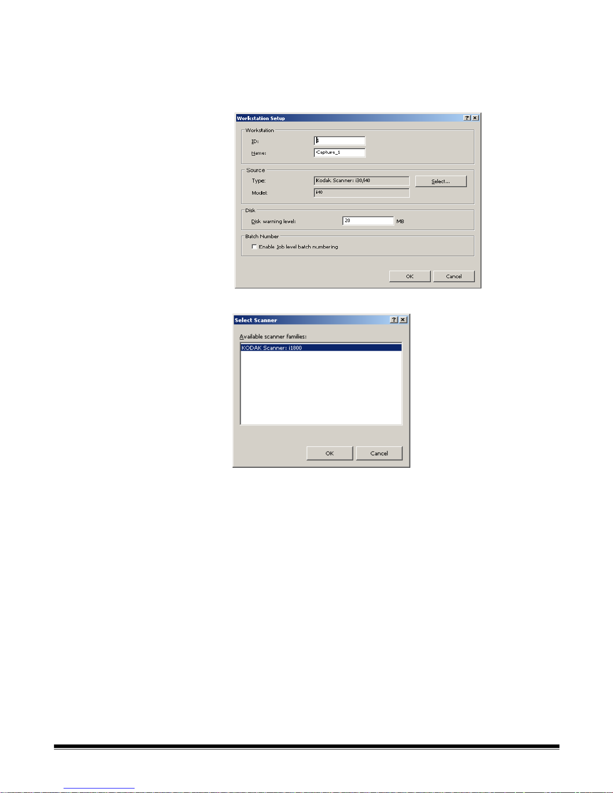
The first time you start Capture Pro Sof tware the m essage, Y our sc anner has
not been selected. Do you want to set it up now? is displayed. Click Yes to
display the Workstation Setup screen. From this screen you can select the
scanner you will be using from the list of available scanners. Subsequent
launches of the software will bypass these steps.
1. Click Select. The Select Scanner screen will be displayed.
2-4 A-61635 December 2010
2. Select the scanner you have installed on your PC and click OK.
3. Click OK on the Workstation Setup screen.
4. After selecting your scanner, the registration screens will be displayed.
Register your copy of Kodak Capture Pro Software to continue using the
software after the initial 14-day period.
NOTE: An Internet connection is required to complete the registration
process. Follow the on-screen prompts and enter the required
information. After submitting the registration, you have 14 days to
use the software before you need to enter the code that will be sent
to your registered e-mail address to fully unlock the software.
Page 10

Terminology Before you begin a basic understanding of some of the terminology used in
Kodak Capture Pro Software is helpful.
Kodak Capture Pro Software is “job” based. A job is a configuration that is
setup to capture and process a set of documents that you want to scan.
To scan documents in a job, you need to create a batch to hold the scanned
documents, images and data before you o utput them.
Kodak Capture Pro Software organizes scanned documents in the following
hierarchy:
• Batch: contains one or more scanned documents (similar to a folder or
hanging file containing several sepa rate documents).
• Document: contains one or more page(s) related to a single item (e.g., the
contents of an envelope).
• Page: are physical sheets of paper that are fed through the scanne r to
produce images.
• Image: electronic representations of scanned pages.
Output is the process of sending the batch to the desired output system /
location in the format that you chose.
NOTE: See Appendix A, Glossary for a full listing Kodak Capture Pro Software
terminology.
A-61635 December 2010 2-5
Page 11
Batch Manager
dialog box
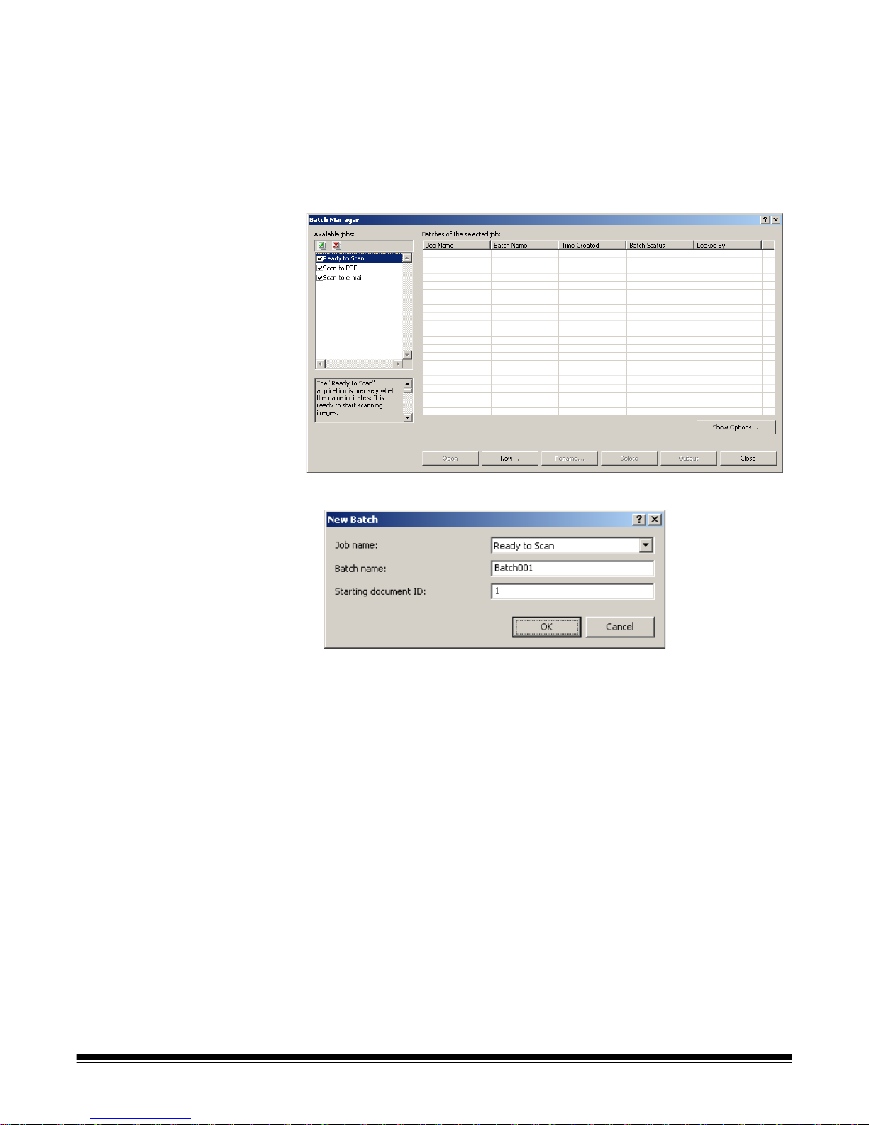
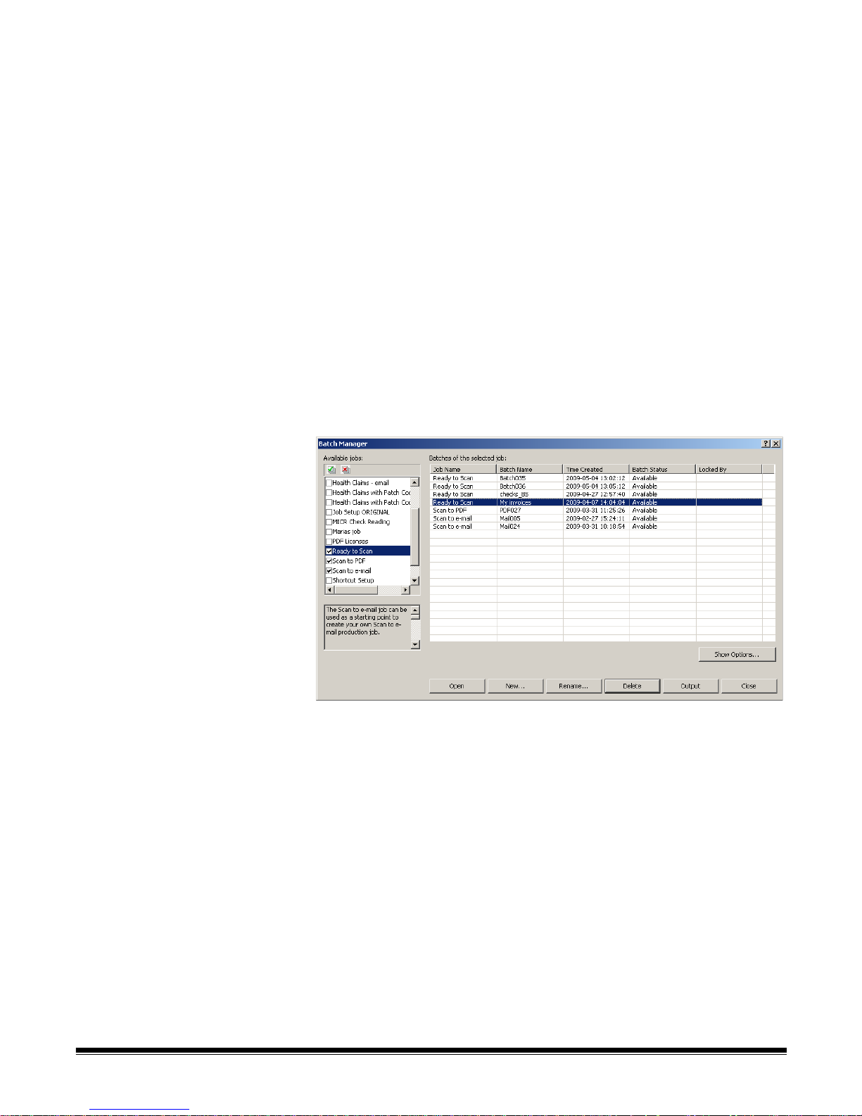
When you log into Kodak Capture Pro Software, the Batch Manage r dialog box
will be displayed. The Batch Manager dialog box can also be displayed by
selecting Batch>Open. Use this box to manage all the batches associated
with your job setups.
Available jobs — lists all of your job setups. Select a batch from any of these
job setups.
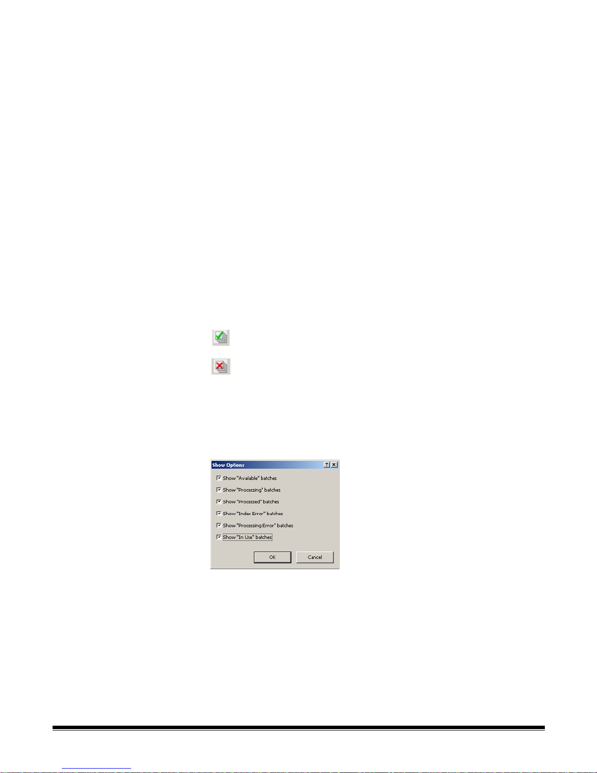
Click to display all the batches in all of the job setups.
Click to hide all the batches in all of the job setups.
Batches of the selected job — displays the Job Name, Batch Name, Time
Created, Batch Status, and Locked By fields for the selected jobs.
Show Options — displays the Show Options dialog box, which allows you to
select what sta tes (i.e., Available, Processing, etc.) to display in the Batch
Status field on the Batch Manager dialog box.
Open — displays the batch that you selected on the list. The Open com ma n d
will not open a batch listed as In Use. You must have read/write permission for
the scanned image location to open an existing batch.
New — displays the New Batch dialog box, which allows you to create a new
batch.
Rename — displays the Rename Batch dialog box, which allows you to
rename the selected batch.
Delete — deletes the selected batch. A confirmation box will be displayed to
confirm your deletion.
Output — sends the batch to be processed.
Close — closes the dialog box.
2-6 A-61635 December 2010
Page 12
Creating a new batch When you want to scan documents, you need to create a new batch or ope n
an existing batch to scan the documents into. In most cases your system
administrator has already configured the jobs you will use. These jobs will be
listed in the Batch Manager dialog box.
To create a new batch:
1. Launch Kodak Capture Pro Software. The Batch Manager dialog box will
be displayed.
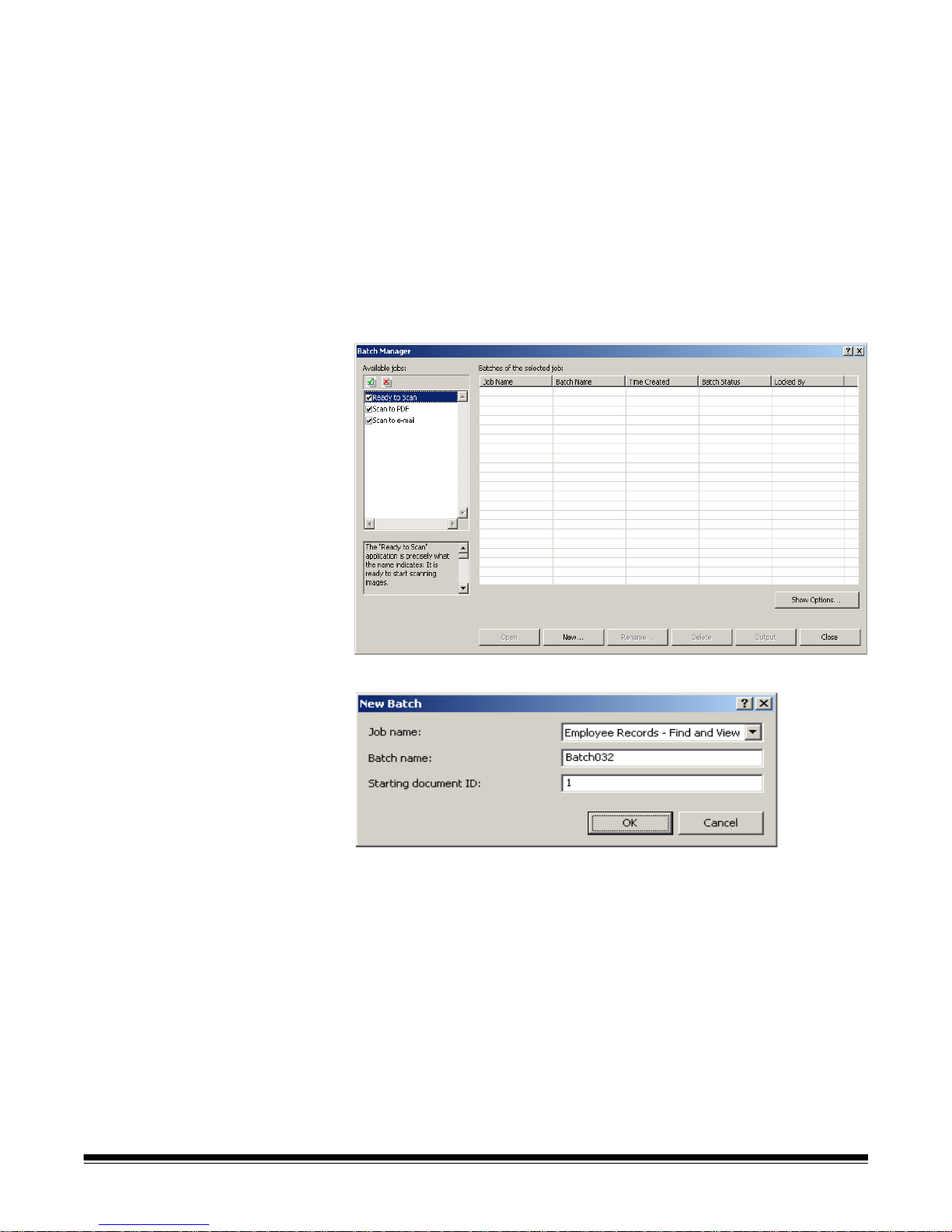
1. Select New. The New Batch dialog box will be displayed.
2. Select a job setup from the Job name drop-down list. Your new batch will
be captured and output as defined in this job setup.
3. If applicable, enter a new batch name in the Batch name field. By default,
Kodak Capture Pro Software suggests a new batch name based upon the
last batch name created for the job setup. For example, if the last batch
name is Health030, then the new batch name default will be Health031.
You will not be able to enter a value is Enable Job Level batch
numbering is unchecked on Workstation Setup dialog box.
4. If applicable, enter the starting do cument ID. The starting document ID is
the ID you want to assign to the first document in a batch. In most cases,
that ID is 1. By default, the software suggests a starting document number
based upon the job setup.
5. Click OK. The Image Viewer will be displayed on the Main window with the
batch name you assigned. The Image Viewer, Batch Explorer, and
Thumbnail Viewer will remain blank until you start scanning.
A-61635 December 2010 2-7
Page 13
Opening an existing
To open an existing batch:
batch
1. Select Batch>Open. The Batch Manager dialog box will be displayed.
Depending on your settings, the batches from all of your job setups will be
displayed.
2. Highlight the batch you want and click Open. The batch you selected will
be displayed in the Image Viewer and the Batch Explorer. You can now
work in this batch.
NOTE: If you are scanning in a multiple-scanner environment and the
batch you selected is already opened at anothe r wo rks tation,
Kodak Capture Pro Software will not allow you to open the batch.
The message, The batch cannot be opened because it is
currently in use by another user will be displayed.
Deleting a batch Deleting a batch erases both the images and batch subdirectory structure of
the selected batch.
1. Select Batch>Open. The Batch Manager dialog box will be displayed.
Depending on your settings, the batches from all of your job setups will be
displayed.
2-8 A-61635 December 2010
2. Highlight the batch you want to delete and click Delete. The message, Are
you sure you want to delete the selected batch “XXXXX”? will be
displayed.
3. Click OK.
Page 14
Using a job This section provides the basic steps for creating a new batch, scanning your
documents and outputting a batch. Detailed information regarding indexing,
setting up OCR zones, patch reading, selecting different output sources, etc.
can be found in other chapters of this User’s Guide.
NOTE: There are several ways to complete an action when using Kodak
Capture Pro Software. For example, if you want to open a batch, you
can select Batch>Open from the menu bar, you can click the Open
Batch toolbar button or you can press the F3 shortcut key. For the
purpose of this manual, all actions are described by using the menu
bar. For a complete list of menus, toolbar buttons and function keys
see Chapter 3, The User Interface.
1. If you have not already started Capture Pro Software, do so now. The
Batch Manager dialog box will be displayed.
2. Click New. The New Batch screen will be displayed.
3. Select the desired job setup from the Job name drop-down box. The Batch
name and Starting document ID are automatically filled in. You may
change these if desired.
A-61635 December 2010 2-9
Page 15

4. Click OK. The main screen will be displayed and you are ready to start
scanning.
5. Place the stack of documents you want to scan in the input tray of your
scanner.
6. Click Start. The scanner will feed the pages.
7. When your documents have been scanned, you can perform any
necessary editing options (i.e., remove blank pages, rotate imag es, crop
images, etc.). See the next section, “Editing options” for a brief d escriptio n
of some of the options available.
8. When your batch is how you want it, select Batch>Output. The batch
output task begins and the New Batch screen will be displayed allowing
you to start another scanning session while processing is being done in the
background.
Your scanned images will be delivered to the location designated on the
Capture tab in Job Setup.
2-10 A-61635 December 2010
Page 16

Editing options Before outputting your batch, review your images to be sure they are as you
want them. If you need to make some adjustment s, tools are availab le for your
use. This section provides procedures for some of the more commonly used
editing functions (i.e., rotating images, deleting images, cropping ima ges, etc.).
Procedures for splitting and merging images can be found in Chapter 7, Page
Setup.
All menu options and toolbar options are described in Chapter 3, The User
Interface.
Rotating images Kodak Capture Pro Software allows you to automatically ro tate your images as
they are being scanned (this is setup using Page Setup before scanning) or
manually rotate them after they are scanned. Images are rotated 90, 180 or
270° clockwise.
To manually rotate images in an existing batch:
1. Click on individual (or groups of) images, pages, or documents from the
Batch Explorer list or in the Image Viewer.
A-61635 December 2010 2-11
2. Select Tools>Rotate> 90, 180, or 270. The rotated images will be
displayed in the Image Viewer.
Page 17

Drawing a region The Draw Region tool allows you to draw a rectangle around a portion of an
image, then blank the area inside the rectangle usin g Blank or crop the image
to the size of the rectangle using Crop.
1. Click on an image that you want to crop or blank in the Image Viewer.
2. Select Tools>Draw Region.
3. Click and drag the draw region cursor to create a rectangle over the part of
your image that you want to select. Release the cursor; the rectangle is
now green.
4. You can now crop or blank the region.
To discard a region:
• Right-click on the image containing the green rect angle and sele ct Deselect
Region.
Cropping images You can crop an area outside a rectangular region that you create using the
Draw Region tool and using the Crop option.
1. Click on the image in Batch Explorer that you want to crop. The image you
selected will be outlined in red in the Image Viewer.
2. Select Tools>Draw Region.
3. Click and drag the draw region cursor to create a rectangle over the part of
your image that you want to save. Release the cursor; the rectangle is now
green.
4. Select Tools>Crop. The image area outside of the green rectangle will be
deleted and only the selected area will remain in the Image Viewer.
2-12 A-61635 December 2010
5. Click OK to save your setting.
Page 18

Blanking out part of an
image
If you want to blank out part of an image, you can draw a region on the image
and use the Blank tool. The area inside the rectangle will be blanked out.
1. Click on an image in Batch Explorer that you want to blank.
2. Select Tools>Draw Region.
3. Click and drag the draw region cursor to create a rectangle over the part of
your image that you want to blank. Release the cursor; the rectangle is
now green.
4. Select Tools>Blank. The image will now display a blank area where you
positioned the green rectangle.
5. Click OK to save your setting.
Attaching pages This option allows you to scan extra pages into an existing document.
1. In the Batch Explorer, select the document that is to receive the
attachment.
2. Click Document>Attach Page.
3. Scan the images. The new pages will be displayed at the end of the
selected document.
Rescanning images When reviewing your batch of scanned images, occasionally you may need to
rescan some documents.
1. Highlight the page or pages you want to rescan.
2. Put the originals in the correct order in the scanner.
3. Click the Rescan icon. The images will be rescanned and placed in their
original scanned positions.
Deleting images If you want to delete selected images from a batch:
1. Select the image you want to delete.
A-61635 December 2010 2-13
2. Select Edit>Delete. The message, Are you sure you want to delete the
selected item(s)? will be displayed.
3. Click Yes to confirm the deletion.
Page 19

Deleting a range of
documents
You can delete a range of documents in an existing batch.
1. Select Document>Delete Range. The Delete Document s in Range dialog
box will be displayed.
2. Enter the beginning number of the document group you want to delete in
the From Document Number field.
3. Enter the ending number of the document group in the To Document
Number field.
4. Click OK.
Removing blank images
from a batch
This option allows you to remove the blank back or front images produced by
the scanner.
1. Select Batch>Remove Blank Images. The Remove Blank Images Setup
dialog box will be displayed.
2. Enter the beginning document number in the batch where you want to
search for blank images in the Start at document field. The default is the
currently active document.
3. Define the byte-size threshold of the images to be verified in the Show
Black and White images below and Show Color/Grayscale images fields. A
good setting for typical business documents is 3000 bytes in 200 dpi black
and white.
2-14 A-61635 December 2010
4. Click Check only back sides to remove only the blank back sides of the
images in a batch.
5. Click Pre-select all if all images are candidates for deletion.
Page 20
6. Define the number of columns and rows you want to display in the Display
layout field. On a 1024 x 768 SVGA screen, a matrix of 14 x 7 allows you to
check 98 images per screen.
7. Click OK to accept the values you entered.
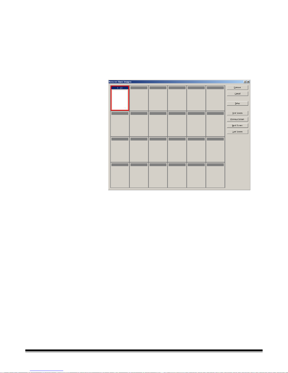
After the batch is examined, Kodak Capture Pro Software displays all the
images that match the criteria you set up (for ex amp l e, back sides below
5000 bytes) the Remove Blank Images window. These images are
displayed in a red highlight color. All colored images are considered blank
and ready to be deleted.
• If no blank images are displayed in the Remove Blank Images window,
it means that Kodak Capture Pro Software cannot locate images in your
batch that match your criteria. You can click Setup on the Remove
Blank Images window to reopen the Remove Blank Images Setup
dialog box and enter higher threshold numbers (in bytes) for the black
and white and/or color/grayscale images.
8. By default, all the blank images are outlined in red and selected for
deletion. Select any blank images you do not want to delete by clicking
them individually. The red outline disappears on those images.
9. Use the First Screen, Previous Screen, Next Screen and Last Screen
buttons to help you navigate through all the possible blank images in the
batch.
10. Click Remove. The message Remove all selected images? will be
displayed.
11. Select Yes to confirm the deletion of the blank images. Capture Pro
Software removes the blank images still outlined in red, repaginates the
documents, and updates the available batch and hard disk capacity.
A-61635 December 2010 2-15
Page 21
Outputting (processing)
your batch
When all of your editing changes are complete, you are ready to output your
batch.
Kodak Capture Pro Software allows you to output (or process) one batch at a
time or output all available batches at once.
To output the current batch in a job setup:
1. Select Batch>Output.
When your batch is queued for output, the New Batch dialog box will be
displayed allowing you to scan another batch of documents.
2. Click OK to continue scanning images into the new batch. When you
output a batch, it is processed according to the System Output Destination
selected in the Output tab of the Job Setup dialog box. This typically results
in the batch being copied to an output subdirectory path.
To output all available batches in a current job setup:
•Select Batch>Output All. The Batch Manager dialog box will be displayed
where you can select one or more batches to be outputted.
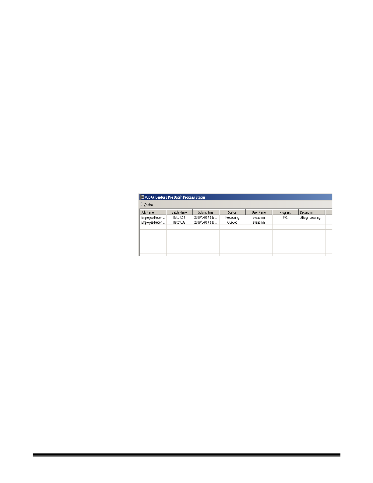
To view the output progress:
•Select Batch>View Batch Output Status. The Kodak Capture Pro Batch
Process Status window will be displayed.
This window will update you on the progress of your batches as they are
outputted. When outputting in the background, scanning takes higher
priority. Output will be slowed until scanning is finished.
NOTE: If you experience issues when outputting your job, see Chapter 11,
Troubleshooting for problem resolution.
2-16 A-61635 December 2010
Page 22

3 The User Interface
Contents Main window ..............................................................................................3-2
Menu bar....................................................................................................3-4
File menu................... ... .......................................... ...............................3-4
Setting up your workstation................................................................3-5
Batch menu............................................................................................3-6
View menu .............................................................................................3-7
Capture menu ............... ... .......................................... ............................3-8
Document menu.....................................................................................3-9
Edit menu.............................................................................................3-10
Tools menu........................................................................................... 3-11
Index menu................... ... .......................................... ..........................3-13
Help menu............... ... ... .......................................... .............................3-14
Toolbars ...................................................................................................3-15
Capture toolbar ................ .... .......................................... ......................3-15
Batch toolbar........................................................................................3-15
Document toolbar.................................................................................3-15
View toolbar .........................................................................................3-16
Navigation toolbar................................................................................3-16
Flag toolbar..........................................................................................3-17
Edit toolbar...........................................................................................3-17
Index toolbar................. .......................................... .............................3-18
Scanner Adjustments toolbar............................ ... ... ... .... ... ... ... ... .... ... ...3-18
Keyboard shortcuts..................................................................................3-19
Batch Explorer .........................................................................................3-20
Image Viewer...........................................................................................3-20
Image context-sensitive menu .............................................................3-21
Thumbnail Viewer .......... ... ... .... ... .......................................... ...................3-23
Thumbnail Viewer context-sensitive menu...........................................3-23
Index window .............. ... ... ... .... ... ... .......................................... ................3-23
Information window..................................................................................3-24
Batch Status window............................................................................3-25
Changing the Main window interface.......................................................3-26
A-61635 December 2010 3-1
This chapter provides descriptions of the Ma in windo w of Kodak Capture Pro
Software, as well as descriptions of the menu bar, toolbars and viewers.
Page 23
Main window The Main window has the following components.
1 Program title bar — provides the name of the job setup.
2 Menu bar — provides the following menu items: File, Batch, View,
Capture, Document, Edit, Tools, Index and Help.
3Toolbars — provides the following toolbars: Capture, Batch, View,
Document, Navigation, Flag, Edit and Index.
4 Batch Explorer — lists all the document folders, pages and image files in
the batch.
5 Image Viewer — displays the images in a batch. The Image Viewer can
be configured to show 1, 2, 4, 8 or more images at a time.
6 Thumbnail Viewer — displays thumbnails of all the images in the batch.
7 Index tab — when you click the Index tab (located on the right-hand side
of the Main window) the Index window is displayed which provides batch
or document level indexes.
3-2 A-61635 December 2010
Page 24
8 Information tab — when you click the Information tab (located on the
right-hand side of the Main window) the Information window is displayed
which provides detailed statistics on the batch, document, page and
image.
A-61635 December 2010 3-3
Page 25

Menu bar The Menu bar provides the following menu items: File, Batch, View, Capture,
Document, Edit, Tools, Index, and Help.
File menu The File menu contains the following options:
Job Setup — displays the Job Setup dialog box, which allows you to set up all
the parameters for a job setup. See Chapter 4, Job Setup for more information.
Keyboard shortcut: J.
Page Setup — displays the Page Setup dialog box, which allows yo u to select
a predefined page setup or create your own custom pa ge setup for your job
setup. Kodak Capture Pro Software comes with several pre-defined page
setups. The list of predefined page setups varies depending on the scanner
being used. See Chapter 7, Page Setup for more information.
Workstation Setup — displays the Workstation Setup dialog box, which
allows you to select the scanner attached to your PC for scanning documents
into Kodak Capture Pro Software. If license d, you ma y also sele ct Au to Imp ort
to automatically import images into Kodak Capture Pro Software. See the next
section entitled, “Setting up your workstation” for procedures.
Import Job Setup— displays the Import dialog box, which allows you to
import a job setup. See Chapter 4, Job Setup for more information.
Export Job Setup — displays the Export dialog box, which allows you to
export the job setup to a file. See Chapter 4, Job Setup for more information.
User Setup — displays the User Setup dialog box, which allows the
administrator to set up and manage users of Kodak Capture Pro Software. See
Chapter 9, User and Group Setup for more information.
Change Password — displays the Change Password dialog box, which
allows you to change your password.
To change a password:
1. Select File>Change Password. The Change Password dialog box will be
displayed.
2. Enter your Old Password, then enter your New Password.
3. Confirm your password by entering your new password in the Confirm
Password field.
4. Click OK.
Language — allows you to select the language in which the user interface is
displayed. Supported languages are: English, French, Italian, German,
Portuguese-Brazilian, Dutch, Spanish, Simplified Chinese, Traditional
Chinese, Swedish, Korean, Turkish, Czech, Russian and Japanese.
To change the language:
1. Select File>Language.
2. Select the desired language. The user interface will be displayed in the
selected language.
3-4 A-61635 December 2010
NOTE: The Scanner Setup dialog box (TWAIN Driver) may display the wrong
text characters when the default language is a Western language and
the user changes to an Asian language. To solve this, use the system
"Regional and Language options" to set the "Language for nonUnicode Programs" to the desired Asian language.
Page 26
Measurement System — allows you to select US or Metric units.
Print — displays the Print Setting dialog box for the selected printer, which
allows you to print scanned documents. Keyboard shortcut: Ctrl + P.
Save As PDF — displays the Save as PDF dialog box, which allows you to
save scanned images to a searchable or unsearchable PDF format.
Logout — logs out the current user.
Minimize to System Tray — minimizes the Capture Pro Software application
but does not close the software.
Exit — closes Kodak Capture Pro Software. Keyboard shortcut: Alt + F4.
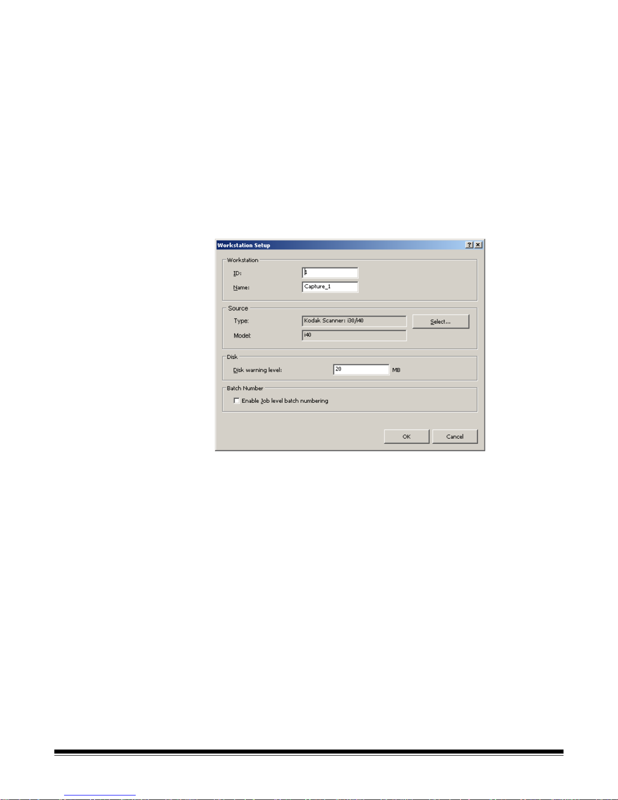
Setting up your workstation When you select File>Workstation Setup, the Workstation Setup screen is
displayed. From this screen you can setup the workstation information and
choose the scanner you want to use.
1. Enter the ID and Name of your workstation. In a multi-scanner environment
the ID and name must be unique.
2. Click Select. The Select Source dialog box will be displayed and provides
a list of available scanners and other sources, such as Auto Import,
depending on your license.
3. Select the source you want to use and click OK.
4. Enter the desired Disk Warning Level in megabytes (MBs). You will receive
a warning if the free space on the disk falls below this level.
5. Check Enable job level batch numbering if you want the batch sequence
number to be kept independently for each job. If this option is checked,
numbering will be maintained at the job level. If not checked, numbering
will be maintained at the system level. For example:
System Level Job Level
Invoices INV001 Invoices INV001
Claims CLM002 Claims CLM001
Records RCD003 Records RCD001
Invoices INV004 Invoices INV002
6. When finished, click OK.
A-61635 December 2010 3-5
Page 27

Batch menu The Batch menu contains the following options:
New — displays the New Batch dialog box, which allows you to create a new
batch. See Chapter 2, Installing the Software and Getting Started for
procedures.
Open — displays the Batch Manager dialog box, which allows you to open an
existing batch. Keyboard shortcut: F3. See Chapter 2, Installing the Software
and Getting St arted for procedures.
Rename — displays the Rename Batch dialog box, which allows you to
rename a current batch.
Remove Blank Images — displays the Remove Blank Images Setup dialog
box, which allows you to remove the blank back or front images produced by
the scanner. See Chapter 2, Installing the Software and Getting Started for
procedures.
Output — starts processing all images in the current batch. Keyboard
shortcut: O. See Chapter 2, Installing the Software and Getting Started for
procedures.
Output All — starts processing all images in all batches of the current job.
View Batch Output Status — displays the Kodak Capture Pro Batch Status
window, which provides information on the progress of your outputting
commands.
Clear — erases all the images in a batch, but keeps the batch subdirectory
structure intact.
Delete — erases both the images and batch subdirectory structure of the
selected batch. See Chapter 2, Installing the Software and Getting Started for
procedures.
Delete to End of Batch — erases all the images from the selected image to
the last image in the batch.
3-6 A-61635 December 2010
Page 28
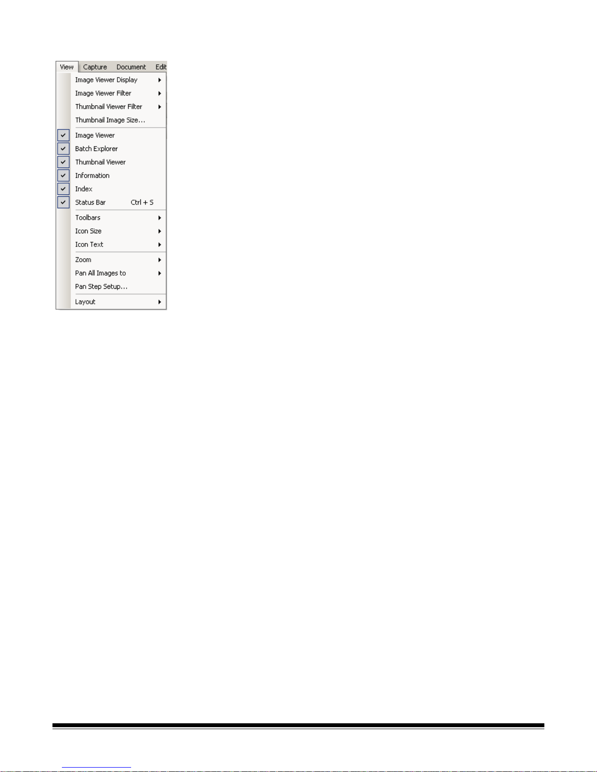
View menu The View menu contains the following options:
Image Viewer Display — allows you to select a grid of 1, 2, 4 or 8 images to
display in the Main window . Selecting Customize d isp lays the Custom Layo ut
Setup dialog box, which allows you to specify another grid size.
Image Viewer Filter — allows you to specify one or more types of images that
will be displayed in the Image Viewer of the Main window. You can select one
or more of the following: Front, Back, Black & White, Grayscale, and Color.
Thumbnail Viewer Filter — allows you to specify one or more types of images
that will be displayed in the Thumbnail Viewer of the Main window. You can
select one or more of the following filters: Front, Back, Black & White,
Grayscale and Color.
Thumbnail Image Size — displays the Thumbnail Image Size Setup dialog
box, which allows you to specify the size of each thumbnail that will be
displayed in the Main window.
Image Viewer, Batch Explorer, Thumbnail Viewer, Information, Index,
Status Bar — these commands allow you to select whether the corresponding
components are displayed in the Main window. The keyboard shortcut for
Status Bar is Ctrl + S.
Toolbars — allows you to view or hide the following toolbars: Capture, Batch,
View, Document, Navigation, Flag, Edit, and Index. Detailed information
regarding the toolbars can be found later in this chapter.
Icon Size — allows you to specify Small, Medium or Large icons.
Icon Text — allows you to specify if icon labels will be displayed and, if so, on
the right or below the icons.
Zoom — increases or decreases the displayed size of an image.
• Actual: displays the image at actual size (one scanned pixel equals one
pixel on the Image Viewer.)
• Zoom In: increases the image display by the increment specified in the
Zoom Step Setup dialog box.
• Zoom Out: decreases the image display by the increment specified in the
Zoom Step Setup dialog box.
• Zoom Step: displays the Zoom Step Setup dialog box, which allows you to
specify the increment (15%, 20%, 25%, 30%, 35% or 40%) that the image
size is changed when you use the Zoom In and Zoom Out commands.
Pan All Images to — enables you to move all images around the Image
Viewer pane at once. You can pan to the Top, Bottom, Left or Right of the
images.
Pan Step Setup — displays the Pan Step Setup dialog box, which allows you
to specify the desired number of pixels (5, 10, 15, 25, 50 or 100) an image
moves when you use the Pan commands.
Layout — allows you to change between the Classic and Enhanced layout
modes.
A-61635 December 2010 3-7
Page 29

Capture menu The Capture menu contains the following options:
Start — enables the scanner and starts the transport. Keyboard shortcut: F7.
Stop — clears and stops the transport and disables the scanner. Keyboard
shortcut: F6.
Page Setup List — displays the Page Setup List dialog box, which allows you
to select from the defined page setups. Keyboard shortcut: F2.
Capture modes — determines how a batch is scanned by allowing you to
select one of the following settings:
• Two-Sided: scans the front and back of a page.
• One-Sided Front: scans the front of a page.
• One-Sided Back: scans the back of a page.
Select Scanner — displays the Workstation Setup dialog box, which allows
you to select the scanner you want to use.
Manual Import Images — allows you to import image files created from
another source (e.g., an engineering drawing scanner) into the currently
displayed document in Capture Pro Software.
When you select Manual Import Images, the Open dialog box will be
displayed. Navigate to the directory where you wa nt to import images from and
select the desired image file(s). BMP, JPEG, PDF and TIFF image files can be
imported. The images that you selected to be imported will be inserted
immediately before the image that is selected in the currently displayed
document. If there are no selected images, the imported images will be
appended to the end of the current document.
Both single- and multi-page TIFF files are supported. When importing a multipage TIFF file, each image in the file will be imported as a separate image into
the document.
More than one image file can be selected for import. If more than one image
file is selected, the images will be imported in alphabetical/numerical order
according to their image file name.
Auto Import Setup — displays the Auto Import Setup dialog box which allows
you to configure auto import “watch folders”. You can identify watch folders
and assign them user friendly names using the Auto Image Setup dialog box.
You can also identify directories for archiving and error handling, assign error
threshold levels, specify auto import batch separation rules, and timeout
intervals. See Chapter 10, Auto Import for more information.
Set Image Address — displays the Image Address dialog box, which allows
you to change image address settings for your batch. This option becomes
active only if you have a scanner capable of image addressing.
Set Counter — displays the Set Counter dialog box, which allows you to reset
the sequential counter value assigned (and optionally printed) to the next p age
scanned. This option becomes active only if you have a scanner with a
counter.
3-8 A-61635 December 2010
Page 30

Document menu The Document menu contains the following options:
New — creates a new document with a document number equal to the last
document number plus "1". Keyboard shortcut: Ctrl + Enter.
NOTE: For some scanners, selecting New also enables the scanner and
starts the scanner transport/feeder or flatbed.
Attach Page — allows you to scan extra ima ges and add them as p ages to an
existing document. Keyboard shortcut: F4.
Insert Pages — inserts additional pages into a scanned document. Keyboard
shortcut: Insert.
NOTE: If image address and patch detection are set, Insert Pages will not
cause a document separation when a document patch is detected.
Rescan Pages — repeats scanning of the document. Keyboard shortcut: R.
Split Document — splits the selected document into two documents.
Merge into Previous — places the document currently be ing scanned into the
previous document.
Delete — deletes the currently opened document. Keyboard shortcut: F8.
Delete Range — displays the Delete Documents in Range dialog box, which
allows you to delete a range of documents in the batch.
Delete to End of Document — allows you to delete the selected image and
all subsequent images of a document. This command removes images from
your hard drive. You cannot undo this function.
Go to Document — allows you to select to go to the first, last, next or previous
document in the batch, or you can select a Document Number to go to a
specific document within a batch.
Go to Image — opens the Go to Image dialog box, which allows yo u to
navigate to a specific image in the current document. Keyboard shortcut: I.
A-61635 December 2010 3-9
Page 31

Edit menu The Edit menu contains the following options:
Undo — reverts one level of the last action. If an action cannot be undone, a
message will be displayed. Keyboard shortcut: Ctrl + Z.
Copy — copies a selected image for pasting to another location. Keyboard
shortcut: Ctrl + C.
Copy Image Area — after using Draw Region to create a region on your
image, this option allows you to copy this region to another location. Keyboard
shortcut: Ctrl + I.
Copy Image to Job Setup — displays the Copy Image to Job Setup dialog
box, which allows you to import images into the Bar Code window or the OCR
window to create bar code or OCR zones.
Select All — selects all images in the current batch. Keyboard shortcut:
Ctrl + A.
Select Document — selects all images in the current document.
Select Filtered — selects all images whose filtered parameters are selected.
Deselect All — deselects all images. Keyboard shortcut: Ctrl + D.
Select Flagged — selects all images that are flagged. Keyboard shortcut:
Ctrl + F.
Delete — deletes the selected images from the batch. Keyboard shortcut: Del.
3-10 A-61635 December 2010
Page 32

Tools menu The Tools menu contains the following options:
Selector — displays the Pointer tool, which allows you to select images.
Keyboard shortcut: S.
Selection mode — select Image, Page or Page Side.
• If you select Image, you can click on an image in the Image Viewer and just
the image will be selected.
• If you select Page, you can click on the image and the entire page, front an d
back, black and white and color/grayscale, will be selected.
• If you are scanning multiple images for a side (dual-stream scanning), when
you select Page Side, and click on a front image, all front images will be
selected. If you click on a back image, all back images will be selected.
Magnify — enlarges a portion of an image. When you select Magnify, the
Magnify tool will be displayed. You can enlarge any area where you place the
Magnify tool. (You must click and hold on the image.) Keyboard shortcut: M.
Pan — allows you to move the image ar ound the Ima ge Vi ewer pa ne when the
image is larger than the pane. Keyboard shortcut: P.
Draw Region — allows you to draw a rectangle aroun d a po rtion of a n imag e,
then blank the area inside the rectangle using Blank; or crop the image to the
size of the rectangle using Crop (or copy it using Edit>Copy Image Area).
Magnification Ratio — displays the Magnification Ratio Setup dialog box,
which allows you to select the desired magnification ratio of 100%, 150%,
200%, 250% or 300%.
To magnify an existing image in the Image Viewer or Thumbnail Viewer:
1. Select Tools>Magnify.
2. Click on an image, then hold and drag the Magnify tool over the image.
Rotate — manually rotates the selected image 90, 180 or 270 degrees
clockwise. Kodak Capture Pro Software allows you to automatically rotate your
images as they are being scanned or manually rotate them after they are
scanned.
Intelligent QC — launches the Intelligent QC tool. All selected images will be
available for review and processing. If no images have been selected, all
flagged images will be available. The Intelligent QC tool may also be launched
by right clicking on an image in the Image Viewer or Batch Explorer and
selecting Intelligent QC in the selection list.
A-61635 December 2010 3-11
Page 33

Flag Tool options — allows you to flag an image(s) that may need to be
rescanned or adjusted in some way (e.g., contrast values may need to be
adjusted to provide better image quality). Keyboard shortcut: C.
• Flag Tool: allows you to flag a page, image or both the front and b ack of an
image.
• Flag All Selected: flags all selected images in the batch to be rescanned.
• Flag Document: flags all the images in the selected document.
• Flag Filtered: allows you to apply a filter to images currently displayed in
the Image Viewer. Once you select which viewer you want to apply your
filter to, you can select the Front Side or Back Side, Black and White,
Grayscale or Color images.
• Unflag All Selected: removes the flags from the images currently selected.
• Unflag All: removes any of the previously flagged images in the current
batch.
Split Document — splits a document into two documents. For more
information see Chapter 7, Page Setup.
Crop — allows you to crop out the area outside the rectangle you crea ted
using the Draw Region option. A confirmation box will be displayed when you
select this option. Keyboard shortcut: Ctrl + R.
Blank — allows you to blank out the area inside the rect angle that you created
using the Draw Region option. A confirmation box will be displayed when you
select this option. Keyboard shortcut: Ctrl + B.
3-12 A-61635 December 2010
Page 34

Index menu The Index menu contains the following options:
Edit Index Fields — provides access to the index fields at the batch and
document levels. Keyboard shortcut: E.
Previous Document — displays the index information for the previous
document. Keyboard shortcut: F9.
Next Document — displays the index information for the next document.
Keyboard shortcut: F10.
Next Invalid — displays the index information for the next document in which
an index is invalid. Keyboard shortcut: F11.
Define Enter Key Behavior — allows you to assign an action that you want
the software to take when you press Enter. Options are: go to the Next
Document, go to the Next Invalid document or Save & Exit Indexing.
Zoom Zones — allows you to draw a rectangle around a portion of the image
that you want zoomed for display when editing index fields. This zoom setting
is saved per index field. As a result, you can define a zoom zone for each
index field and the image display automatically zooms to the appropriate part
of the image when that field is edited.
Drag-and-Drop OCR — allows you to populate an index field by drawing a
region on the image. OCR is performed within the region, and the value is
automatically put into that index field. After selectin g the to ol, draw a re ct angle
around the index data to be captured.
NOTE: To properly create OCR special language-specific characters (e.g., «
or ¸) or MICR code characters, select the appropriate language or
MICR font from the drop-down list.
OCR Language — allows you to setup what language will be used for the
OCR function.
Save & Exit Indexing — exits indexing and saves any changes you made to
the batch. Keyboard shortcut: F12.
Cancel & Exit Indexing — exits indexing without saving any changes you
made to the batch.
A-61635 December 2010 3-13
Page 35

Help menu The Help menu contains the following options:
Help — displays the on-line help for Kodak Capture Pro Software. Keyboard
shortcut: F1.
Send Error Report — displays the Send Error Report dialog box, which allows
you to enter a message describing your problem and send it to Kodak.
Tutorial — if you have installed the Tutorial for Kodak Capture Pro Software,
this option will be on the Help menu.
Enter License Code — displays the Enter License Code dialog box, which
allows you to enter the license information necessary to use the software. The
Request Code will be displayed at the top of the box.
Register — displays the Product Registration dialog box which allows you to
register your Kodak Capture Pro Software.
Kodak Capture Pro Online — displays the online help for Kodak Capture Pro
Software.
About Kodak Capture Pro — displays the About Kodak Capture Pro
Software dialog box, which provides information about the current version of
the software. Use this box to view the following information:
•Copyright
• File extension
• File path
• Software serial number
• Software version number
This dialog box also allows you to access System Information which opens the
Files Information window. This window provides information on individual files
within the Capture Pro Software. The Files Information window is read-only.
• File name
• File size
• Creation date
• Version number
• Description
NOTE: Click "X" in the top right-corner to close the Files Information window.
3-14 A-61635 December 2010
Page 36
Toolbars
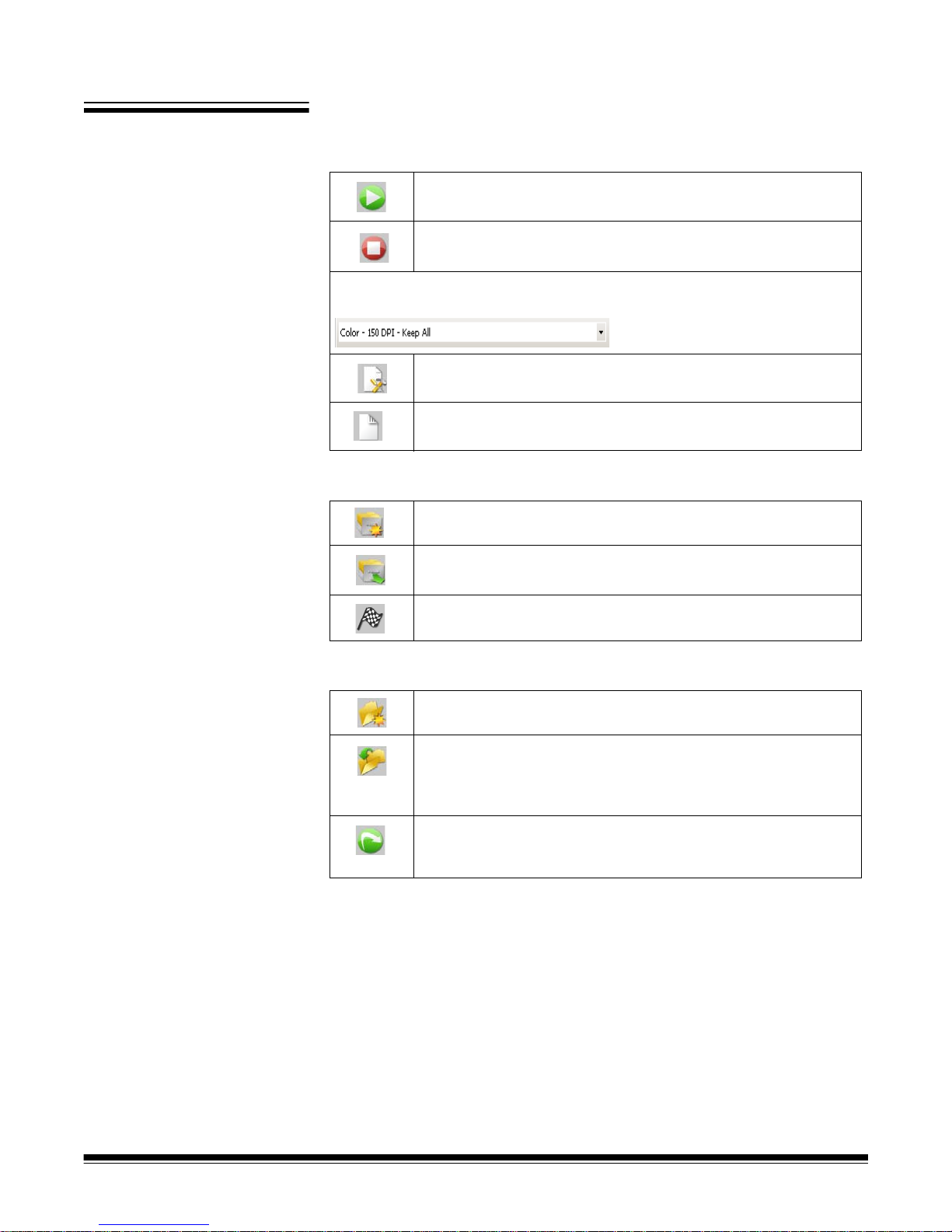
Capture toolbar The Capture toolbar contains the following commands:
Start — starts scanning images on the scanner.
Stop Scan — stops scanning images.
Page Setup name — select a page setup name from the drop -down list that
best fits the job you are scanning.
Page Setup — displays the Page Setup dialog box, which
allows you to set up scanning parameters.
Sides to Capture — allows you to select Two-sided, OneSided Front or One-Sided Back.
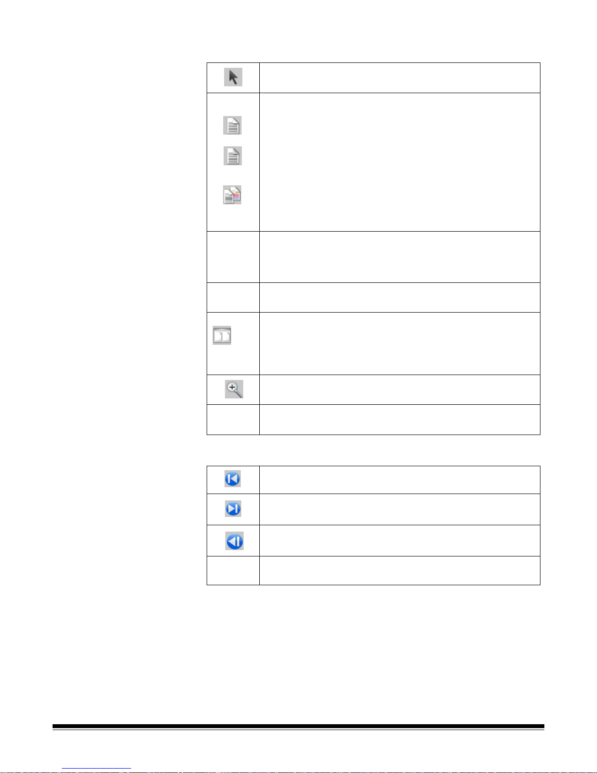
Batch toolbar The Batch toolbar contains the following commands:
New batch — displays the New Batch dialog box, which allows
you to create a new batch.
Open batch — displays the Batch Manager dialog box, which
allows you to open an existing batch.
Output batch — starts outputting all the images in the current
batch.
Document toolbar The Document toolbar contains the following commands:
New document — allows you to add a new document.
Insert Pages — inserts additional pages into a scanned
document. Highlight the first image in a page and the icon
becomes active. Put the additional pages in the scanner and
click this icon.
Rescan pages — repeats scanning of selected parts of the
document. Highlight the page or pages you want rescanned , put
the originals in the scanner and click this icon.
A-61635 December 2010 3-15
Page 37
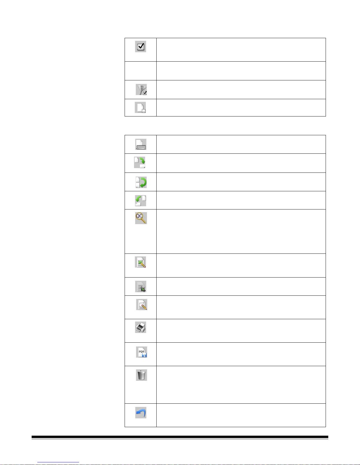
View toolbar The View toolbar contains the following commands:
Selector — displays the pointer tool, allowing you to select
images.
Selection mode — select Image, Page or Page Side.
• If you select Image, you can click on an image in the Image
Viewer and just the image will be selected.
• If you select Page, you can click on the image and the entire
page, front and back, black and white and color/grayscale, will
be selected.
• If you are scanning multiple images for a side (dual-stream
scanning), when you select Page Side, and click on a front
image, all front images will be selected. If you click on a back
image, all back images will be selected.
Magnify — allows you to enlarge a portion of an image. When
you select Magnify, the Magnify tool will be displayed. You can
enlarge any area where you place the tool. (You must click and
hold on the image.)
Pan — allows you to move the image around the window when
the image is larger than the window.
Image Viewer Display — allows you to use the down arrow to
display 1, 2, 4 or 8 images or Customize your la yout. When you
select Customize, the Custom Layout Setup dialog box will be
displayed, allowing you to enter the number of rows and
columns you want to appear in the Image Viewer.
Zoom In — zooms in on all the images in the Image Viewer.
Zoom Out— zooms out on all the images in the Image Viewer.
Navigation toolbar The Navigation toolbar contains the following commands:
First Document — displays the first document of the batch in
the Image Viewer.
Last Document — displays the last document of the batch in
the Image Viewer.
Previous Document — displays the previous document of the
batch in the Image Viewer.
Next Document — displays the next document of the batch in
the Image Viewer.
3-16 A-61635 December 2010
Page 38
Flag toolbar The Flag toolbar contains the following commands:
Flag Tool — allows you to flag a page or image. For example,
you may want to permanently identify images that need to be
rescanned.
Flag All Selected — flags all selected images in the batch.
Flag Filtered — allows you to flag images currently displayed in
the Image Viewer or Thumbnail Viewer.
Unflag All — removes flags from any of the previously flagged
images in the current batch.
Edit toolbar The Edit toolbar contains the following commands:
Edit Index Fields — provides access to the index fields at the
batch and document levels.
Rotate 90 — rotates the selected image(s) 90 degrees
clockwise.
Rotate 180 — rot ates the selected image(s) 180 degrees
clockwise.
Rotate 270 — rotates the selected image(s) 270 degrees
clockwise.
Intelligent QC — launches the Intelligent QC tool. All selected
images will be available for review and processing. If no images
have been selected, all flagged images will be available. The
Intelligent QC tool may also be launched by right clicking on an
image in the Image Viewer or Batch Explorer and selecting
Intelligent QC in the selection list.
Draw Region — allows you to draw a rect angle around a portion
of an image, then remove the area inside the rectangle using
Blank; or crop the image to the size of the rect ang le using Crop.
Crop — allows you to remove the area outside the rect angle you
created using the Draw Region option.
Blank — allows you to blank out the area inside the rectangle
that you created using the Draw Region option. A confirmation
box will be displayed when you select this icon.
Print — displays the Print Settings dialog box, which allows you
to print a complete document or specific images within a
document.
Save as PDF — displays the Save as PDF dialog box, which
allows you to save a complete document or indi vidual images as
a searchable or unsearchable PDF file.
Delete Selected — deletes one or more images selected inside
a document. For example, blank images can be deleted from a
two-sided document; all remaining images are renumbered af ter
the selected images are deleted. A confirmation box will be
displayed when you select this icon.
Undo — reverts to the last crop, blank, or rota tion of an image or
set of images. The Undo option does not revert deletion
commands.
A-61635 December 2010 3-17
Page 39

Index toolbar The Index toolbar contains the following commands:
Front Back
Front Back
Previous document — moves to the previous document
number containing images.
Next document — moves to the next document number
containing images.
Next Invalid — goes to the next document that has an invalid
index.
Zoom Zones — enlarges the display of the index data captur ed
for the current field, allowing you to more clearly see difficult-toread special language-specific characters.
Drag-and-Drop OCR — allows you to drag-and-drop indexing
via Optical Character Recognition (OCR) without entering the
index value. After selecting the tool, draw a rect angle around the
index data to be captured.
OCR Language — allows you to select an OCR language from
the drop-down list.
Save & Exit Indexing — saves the changes on the current
batch and closes the Index window.
Cancel & Exit Indexing — closes the Index window without
saving any changes.
Scanner Adjustments
Toolbar
The Scanner Adjustments Toolbar allows you to change the following scan ning
options directly from the Capture Pro Software Main window:
Threshold — controls the lightness and darkness of the
background in an image. Valid values are 0 to 255. There is
a separate Threshold setting for the front and back images.
Contrast — enhances the edges contained in a document.
The higher the contrast level, the more the image edges will
be enhanced. Valid values are 0 to 100 or -50 to 50
depending on your scanner model. There is a separate
Contrast setting for the front and back images.
iThresholding — when selected, the scanner automatically
determines the optimal Threshold setting for each scanned
page, thus improving overall scanning productivity and
image quality. When selected, the Threshold setting for the
front and back images are grayed out and unavailable for
change.
NOTES:
• The Scanner Adjustments Toolbar is only available and can only be used
with Kodak Document Scanners.
• Any changes made to the settings are temporary and will not modify the
currently selected Page Setup that is being used for scanning.
3-18 A-61635 December 2010
• When a change is made to one of the settings on the toolbar, the setting will
be highlighted in yellow to indicate that a change has been made.
• When the Page Setup to be used for scanning is changed, or if the same
Page Setup is re-selected, the Scanner Adjustments Toolbar settings will be
reset to the values that are defined in the Page Setup.
Page 40

Keyboard shortcuts This section lists common keyboard shortcuts. Where available, the keyboard
shortcuts are shown on the menu item for the function.
+ Zoom in image display
- Zoom out image display
1, 2, 4, 8 Allows you to change the image display between 1, 2, 4 or 8
images
C Flag tool
E Edit index fields (enter Indexing Mode)
Enter New Document
F Fit image display size to the Image Viewer (best fit)
F1 Display on-line Help
F2 Display the Page Setup list (to select a different scanner settings
profile)
F3 Open a batch
F4 Attach a page to the current document
F5 Display the Page Setup dialog box
F6 Stop scanning
F7 Start scanning
F8 Delete the selected document
F9 Move to Next document in indexing mode
F10 Move to Previous document in indexing mode
F11 Move to Next Invalid document in indexing mode
F12 Save index values and exit Indexing mode
I Go to image
J Display the Job Setup dialo g box
O Output the current batch and automatically displays the New Batch
dialog box
P Pan images
M Magnify tool (manual zoom tool)
R Rescan pages
S Selector tool (select images for post scan editing or for moving
images / pages)
Z Draw region
A-61635 December 2010 3-19
Page 41

Batch Explorer The Batch Explorer displays all the document folders, p age and image files for
the batch that is currently open in the Image Viewer. It automatically appears
on the left side of the Main window when the Enhanced layout is active.
• Click an image file in Batch Explorer and the image will be displayed in the
Image Viewer.
• Drag an image file, page file, or document folder to a different location in
Batch Explorer.
• Right-click an image file, page file, or document folder to display a context
sensitive menu for more options.
Image Viewer The Image Viewer is the ar ea where yo ur images ar e displa ye d. You can view
1, 2, 4 or 8 images at a time, or customize the Image Viewer layout.
The title bar contains the batch name and the document number for the
images displayed in the Image Viewer.
To move an image:
1. Select an image.
2. Drag the image to the desired location.
To delete an image:
1. Select an image.
2. Select Edit>Delete. The image will be deleted from the document.
To change the number of images displayed:
1. Select View>Imag e Viewer Dis play.
2. Select 1, 2, 4, 8 or Customize. The Image Viewer displays the selected
layout.
NOTE: If you select Customize the Custom Layout Setup dialog box will
be displayed allowing you to enter the desired number of columns
and rows you want to display.
3-20 A-61635 December 2010
Page 42

Image context-sensitive
menu
When you right-click on an image in the Image Viewer, a menu provides the
following options:
Selection mode — select Image, Page, or Page Side.
• If you select Image, you can click on an image in the Image Viewer and just
the image will be selected.
• If you select Page, you can click on the image and the entire page, front an d
back, black and white and color/grayscale, will be selected.
• If you are scanning multiple images for a side (dual-stream scanning), when
you select Page Side, and click on a front image, all front images will be
selected. If you click on a back image, all back images will be selected.
Copy — copies a selected image for pasting to another location.
Copy Image — after using Draw Region to create a region on your image,
this option allows you to copy this region to another location.
Copy Image to Job Setup — displays the Copy Image to Job Setup dialog
box, which allows you to import images into the Bar Code window or the OCR
window to create bar code or OCR zones.
Rotate — rotates the selected image 90, 180 or 270 degrees clockwise.
Intelligent QC — launches the Intelligent QC tool. All selected images will be
available for review and processing. If not images have been selected, all
flagged images will be available.
Split Document — performs a manual document separation, which splits the
selected document into two documents.
Merge into Previous — appends the selected document to the previous
document to create one document.
Zoom — increases or decreases the displayed size of an image.
• Fits Images to window: fits each image to its pane in the Image Viewer,
regardless of its original size.
• Actual: enlarges an image to its actual physical size.
• Zoom in: enlarges an image by a fixed percentage according to the Zoom
Step setting.
• Zoom out: reduces an image by a fixed percentage according to the Zoom
Step setting.
• Zoom Step: accesses the Zoom Step dialog box, which allows you to
specify a percentage to scale from 15 to 40% in increments of 5%.
Pan All Images to — allows you to move all images to the Top, Bottom, Left,
Right or Same position.
Pan Step Setup — displays the Pan Step Setup dialog box, which allows you
to change the pixel settings for the Pan tool.
Hide Front — hides all the front images in the batch.
A-61635 December 2010 3-21
Hide Back — hides all the back images in the batch.
Hide Black and White — hides all the black and white images in the batch.
Hide Grayscale — h
Hide Color — hides all the color images in the batch.
ides all the gr
ayscale images in the batch.
Page 43

If you select the Flag, Magnify or Draw Region tool before right-clicking on an
image, additional options will appear on the menu.
• If the Flag tool is active, the flag options will be displayed.
- Flag All Selected — places green checkmarks on all the selected
images in the batch. To select more than one image, hold down the
Control key while you click on images in the Image Viewer.
- Flag All — places green checkmarks on all the images in the batch.
- Unflag All — removes the green checkmarks from all the images in the
batch.
- Flag Filtered — takes all the filtered (displayed) images and puts green
checkmarks on them.
•If the Magnify tool is active, the Magnification Ratio option will be displayed.
This option displays the Magnification Ratio Setup dialog box, which allows
you to specify the image size displayed when you use the Magnify tool.
•If the Draw Region tool is active, the options related to this tool will be
displayed.
- Apply Region to Document — places the selected region on all the
images in the document.
- Applies Region to Selected — places the selected region only on the
images you selected.
- Crop — allows you to remove the area outside the rectangle you created
using the Draw Region option. A confirmation box will be displayed when
you select this option.
- Blank — allows you to blank out the area inside the rectangle that you
created using the Draw Region option. A confirmation box will be
displayed when you select this option.
3-22 A-61635 December 2010
Page 44

Thumbnail Viewer The Thumbnail Viewer provides thumbnail versions of all the images in the
batch that is currently open.
To select an image in the Image Viewer:
• Click the thumbnail in the Thumbnail Viewer.
To magnify a thumbnail:
• Left-click on the image and hold it. You can move the magnified area by
continuing to hold.
Thumbnail Viewer
context-sensitive menu
When you right-click on a thumbnail image, the following menu options will be
displayed:
Front or Back — hides all the front or back thumbnails.
Black and White, Grayscale, or Color — hides all the black and white,
grayscale, or color thumbnails.
Thumbnail Image Size —- the Thumbnail Image Size Setup dialog box will be
displayed, allowing you to change the image size.
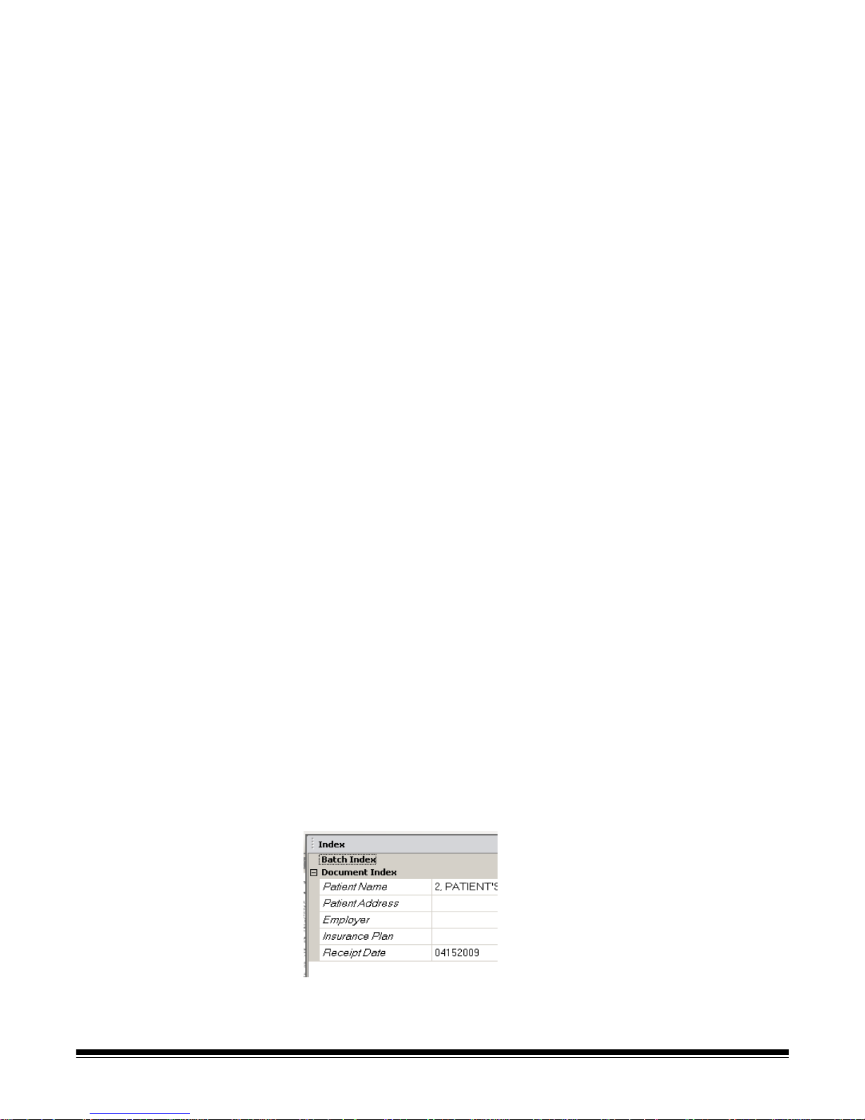
Index window For your convenience, the Index window on the right side of the Image Vie wer
displays the index data for each batch and document that has indexes defined.
It is available as a pull-out tab on the right-hand side of the screen. The index
data can be either shown briefly (hover over the tab stop) or optionally pinned
to the Image Display to continuously view the index fields for all of your images
as they are being scanned into Kodak Capture Pro Software. You can use this
feature to view the index fields for a particular document or the entire batch
and make any necessary corrections to the content within each field.
A-61635 December 2010 3-23
To open the Index window:
• Click the Index window tab on the right side of the Image Viewer. To keep
the window from closing, click the Pin icon once in the top-right corner of the
window.
To close the Index window:
• Double-click the Pin icon or click anywhere outside the Index window. If the
window is pinned open, click the Pin icon once to close it.
Page 45

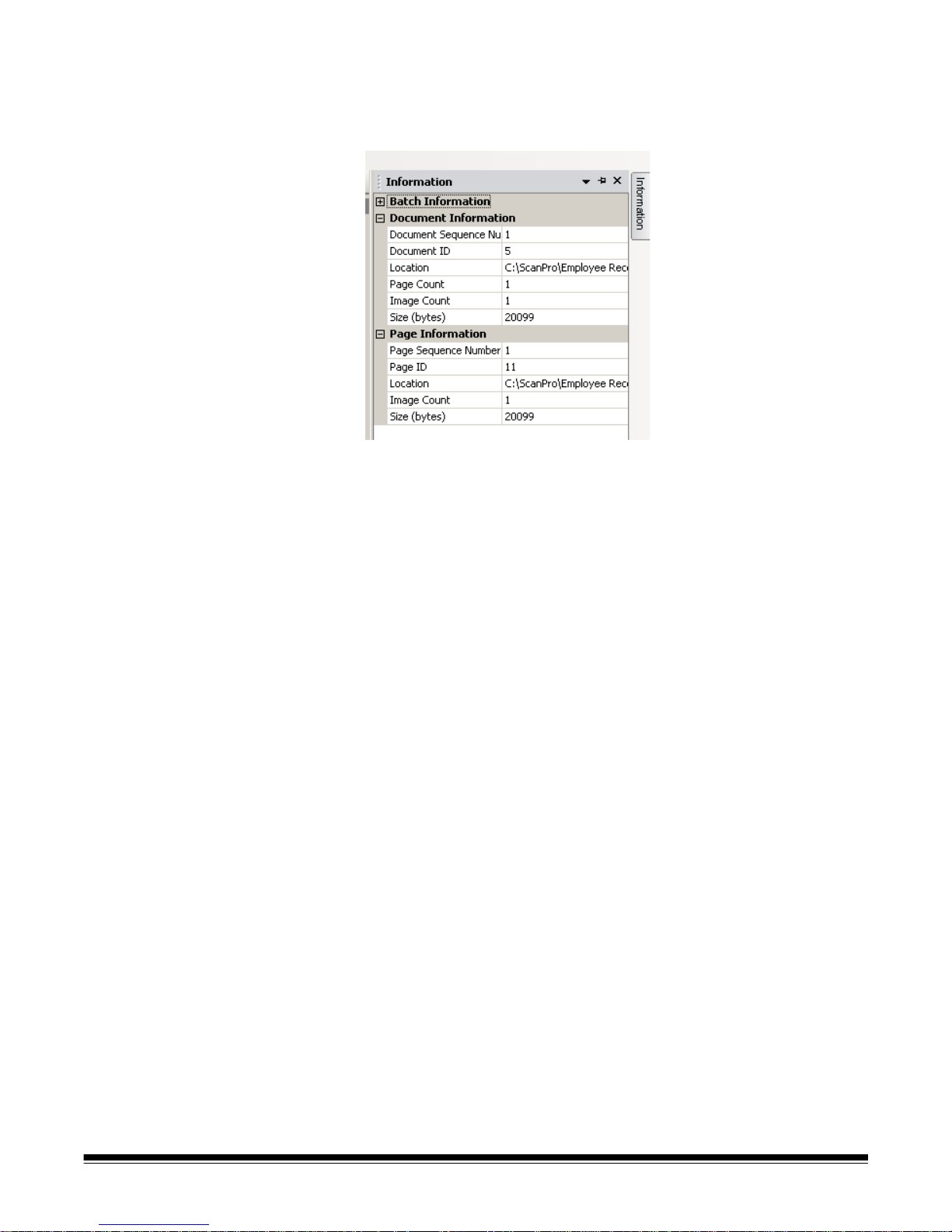
Information window The Information window on the right side of the Image Viewer provides
statistics on the batch that is currently open. You can pin open the Information
window to continuously view batch statistics as your images are being
scanned into Kodak Capture Pro Software.
Information in this window can be displayed for the batch, each document,
each page, or each image. Image information includes the image sequen ce
number, page ID, location on disk, compression, resolution, image size, and
print string.
To open the Information window:
1. Highlight an image, page or document from the Batch Explorer, or highlight
an image from the Image Viewer.
2. Click the Information window on the right side of the Image Viewer . To keep
the window from closing, click the Pin icon once in the top-right corner of
the window.
To close the Information window:
• Double-click the Pin icon or click anywhere outside the Information window.
If the window is pinned open, click the Pin icon once to close it.
3-24 A-61635 December 2010
Page 46

Batch Status window The Kodak Capture Pro Batch Statu s window provides info rmation on b atches
that you are preparing for output from Kodak Capture Pro Software.
Click Control to display the Control menu:
• Show Log — opens a Notepad window and displays the output log.
• Clear log — deletes all the entries in the output log. A confirmation box will
be displayed to verify your choice.
• About — opens the About Kodak Capture Pro Software dialog box, which
has a command for viewing all the files in Capture Pro Software.
• Exit — opens the Shutdown Options dialog box, wh ich contains commands
for exiting Capture Pro Software. Output processing is performed in the
background and independently of Kodak Capture Pro Software. If you close
Capture Pro Software, you will be prompted to continue or stop output
processing.
The Kodak Capture Pro Batch Status window provides the following
information on each batch that has been outputted or is being outputted: Job
Name, Batch Name, Submit Time, Status, Progress, and Description.
• Click on the Job Name to Clear All Errors or Clear Selected Errors.
To view the Batch Status window:
•Select Batch>View Batch Output Status.
A-61635 December 2010 3-25
Page 47

Changing the Main
window interface
As pages are scanned, the images appear in all the displayed viewers: the
Image Viewer , Thumbna il Viewer an d/or Batch Explorer. Capture Pro Software
has two default screen layouts: Classic and Enhanced.
Kodak Capture Pro Software allows you to customize the layout of the Main
window by moving the toolbars, viewers, etc. around to suit your own
preference and hide any unwanted compon en ts of the scree n .
These options apply to the Image Viewer, the Batch Explorer, the Thumbnail
Viewer, the Information window, and the Index window. These icons are
located on the right-top corner of these windows:
Closes any window. To open the window again, select the
window you want to display from the View menu.
Pins the window open. To auto-hide the window, click the Pin
icon.
Auto-hides the window, leaving only the title bar open. To show
the window, move your cursor over the title bar.
Anchor icons (represented by fo ur ve rt ical do ts) are located on
the left-top corner of the windows. When you select an anchor
icon and hold the mouse button down, the image anchor is
released and blue location arrows will be displayed. As you hold
the mouse button down, you can move the windo w to a new
location. When the window is where you want it, release the
mouse button.
3-26 A-61635 December 2010
The size of the images within the viewers can be set as required. The Image
Viewer can be set to a fixed size or remain at the Best Fit default which
displays the images at the best size for the screen.
The toolbars and image windows can be moved or hidden as desire d. Capture
Pro Software remembers the settings for ea ch job when exiting the job. This
means different jobs can be displayed the way you want each job displayed . At
any time you can select View>Layout>Classic (or Enhanced) and reset the
screen back to the default layout.
If you are using the Classic layout and want to add a window from the
Enhanced layout, display the View menu and select a window (i.e., Batch
Explorer, Index window). The additional window will be displayed in the Classic
layout.
Page 48

• Classic layout — displays the Image Viewer only. The number of images
displayed is selectable from 1, 2. 4, 8 or customizable up to 6 columns by 6
rows.
• Enhanced Layout — displays the Image Viewer, Thumbnail Viewer and
Batch Explorer. Each window can be resized as required.
A-61635 December 2010 3-27
Page 49

4 Job Setup
Contents Accessing a job setup................................................................................4-2
The Job Setup dialog box ..........................................................................4-3
Job Setup: Capture tab......................................... ... ... ... .... ... ... ... ...............4-6
General settings - Capture tab ...................................................... ... ... ..4-7
Batch settings - Capture tab..................................................................4-8
Changing the Batch naming settings .................................................4-9
Bar Code & OCR settings - Capture tab................................. ... .... ... ... ..4-9
Separation settings - Capture tab........................................................4-10
By count separation .........................................................................4-10
By Blank page separation ................................................................4-11
Testing your settings ........................................... ... .... ... ... ... ... .... ... ...4-12
Job Setup: Index tab......................................... .... ... ... ... .... ... ... ................4-13
Adding a document index field ..... .... ... ... ...... .... ... ... ... .... ... ... ... ... .... ... ...4-14
Editing a document index field.............................................................4-19
Adding a batch index field ...... ... ... .... ... ... ... ....... ... ... ... .... ... ... ... ... .... ... ...4-20
Input formats........................................................................................4-21
Index Default value specification.........................................................4-30
Transform Expressions........................... ... ... .... ... ... ... .... ... ... ... ....... ... ...4-32
Output formats.....................................................................................4-39
Using the SharePoint Index Setup Wizard ..........................................4-40
Index tab: Database Lookup................................................................4-45
Configuring Database Lookup................... .... ... ... ... .... ... ... ... ... .... ......4-45
Using Database Lookup......................................... .... ... ... ... ... .... ... ...4-50
Edit Index mode...............................................................................4-51
Batch Output....................................................................................4-51
Job Setup: Output tab....................................... .... ... ... ... .... ... ... ... .............4-52
Destination options: File (1) and File (2)..................................................4-52
Setup options for File (1) and File (2)..................................................4-53
Index options for File (1) and File (2)...................................................4-62
Building location and filename formulas using the Location Setup
dialog box.........................................................................................4-65
Using the Index Content Setup dialog box..........................................4-67
System (1) and System (2) options..........................................................4-68
Setting up your e-mail options.............................................................4-69
Setting up your Print options ...............................................................4-71
Setting up your SharePoint options.....................................................4-72
Advanced options ....................................................................................4-72
Auto-deletion .......................................................................................4-73
Auto-orientation...................................................................................4-74
Background color smoothing...............................................................4-75
Image Edge Fill....................................................................................4-76
Image Stamping...................................................................................4-77
Rotate..................................................................................................4-79
Stitch....................................................................................................4-80
Split......................................................................................................4-80
Invoke other program option....................................................................4-82
Remote Output (Network Edition only) ....................................................4-85
A-61635 December 2010 4-1
Page 50
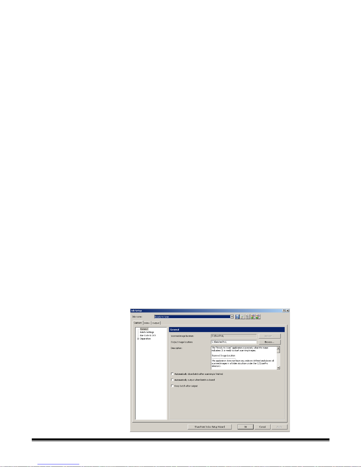
Job Setup: Scanner-specific setting.. .... ... ... ... ... .... ... ... ... .... ...... ... ... .... ... ...4-86
Kodak i1800 Series Scanners.............................................................4-86
Kodak i600/i700/i1400 Series Scanners..............................................4-90
Kodak i200/i100 Series Scanners .......................................................4-91
Kodak i800 Series Scanners...............................................................4-93
Kodak Digital Science 3520 Scanner................................................4-101
The Job Setup function allows you to set up all the parameters for a job. A job
is a configuration that is setup to capture and process a set of documents that
you want to scan. This chapter provides information and procedures on how to
select options on the Capture, Index and Output tabs that allow you to setup
a job to meet your scanning needs. Once a job is setup, you can select the job
required to scan a batch of documents and output them the way you want.
To setup jobs for use with Kodak Capture Pro Software you need to access the
Job Setup dialog box. From Job Setup you can select an already-defined Job
Name and use it as a template to customize the jobs you need to use in your
environment.
There are three predefined jobs that come with Kodak Capture Pro Software:
Ready to Scan — allows you to start scanning documents without any setup
using default settings. This job does not have any indexes defined and places
all scanned images in a folder structure under the C:\ScanPro directory.
Accessing a job
setup
Scan to PDF — similar to Ready to Scan, except when you scan your
document(s), the first page will be displayed in the Image Viewer and you will
be prompted for a filename to be entered as inde x data. The ind ex data is used
as the filename when you output the documents.
Scan to e-mail — similar to the Scan to PDF except a PDF file will be created
and will be included as an attachment to an e-mail. When the scan is
complete, the e-mail software application will be opened with your scanned
attachment and be ready to send to an e-mail address from your e-mail
account.
Depending on what you want to do, you can select one of these job setups to
use as a starting point to setup your job.
• Click File>Job Setup. The Job Setup dialog box will be displayed.
4-2 A-61635 December 2010
Page 51
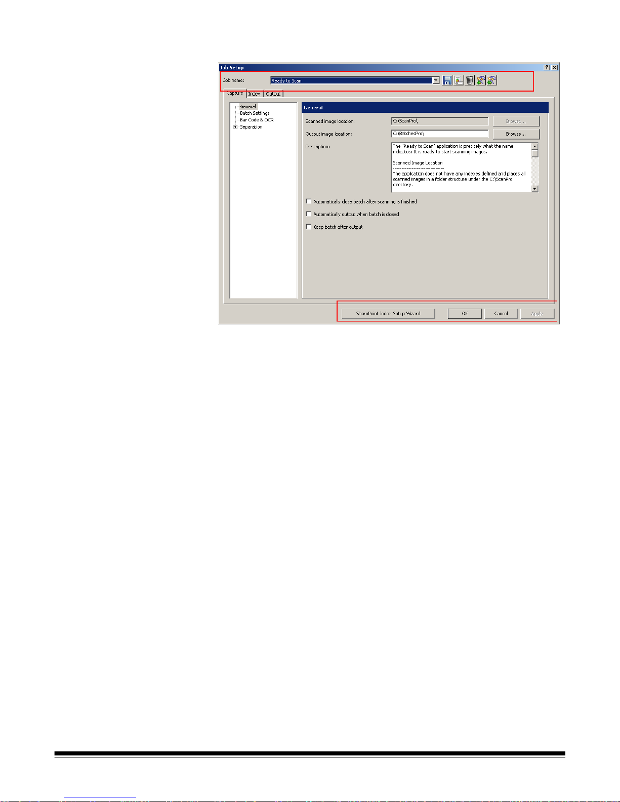
The Job Setup dialog
box
The following information is common to all tabs on the Job Setup dialog box:
Job name — select a job setup name from the drop-down list.
The Job Setup dialog box has three tabs: Capture, Index, and Output.
Detailed information on how to use these tabs can be found in the following
sections.
•The Capture tab allows you to make General, Batch, Bar Code & OCR,
Separation and Scanner settings.
- General settings — define the way images will be stored after scanning.
- Batch settings — select the batch settings for the job setup and put
limits on the number of batch documents and pages.
- Bar Code & OCR settings — create and modify bar code or OCR zones
and set them up for use.
- Separation settings — set up separations by count, blank page, bar
code zone, OCR zone, or patch code.
- Scanner settings — create settings for image addressing and printing
on scanners with those capabilities. Scanner settings such as image
address, printer , and patch settings should al ways be done in Job Setup
and not in Page Setup. Conflicting settings will default to the Job Setup
settings.
•The Index tab allows you to define index fields at the batch and document
levels. The Database Lookup tab allows you to specify the data source,
define how the lookup is performed and what data is used to populate index
fields or validate the contents of index fields.
A-61635 December 2010 4-3
•The Output tab allows you to select the System Output and Advanced
Processing options for the job setup.
Page 52
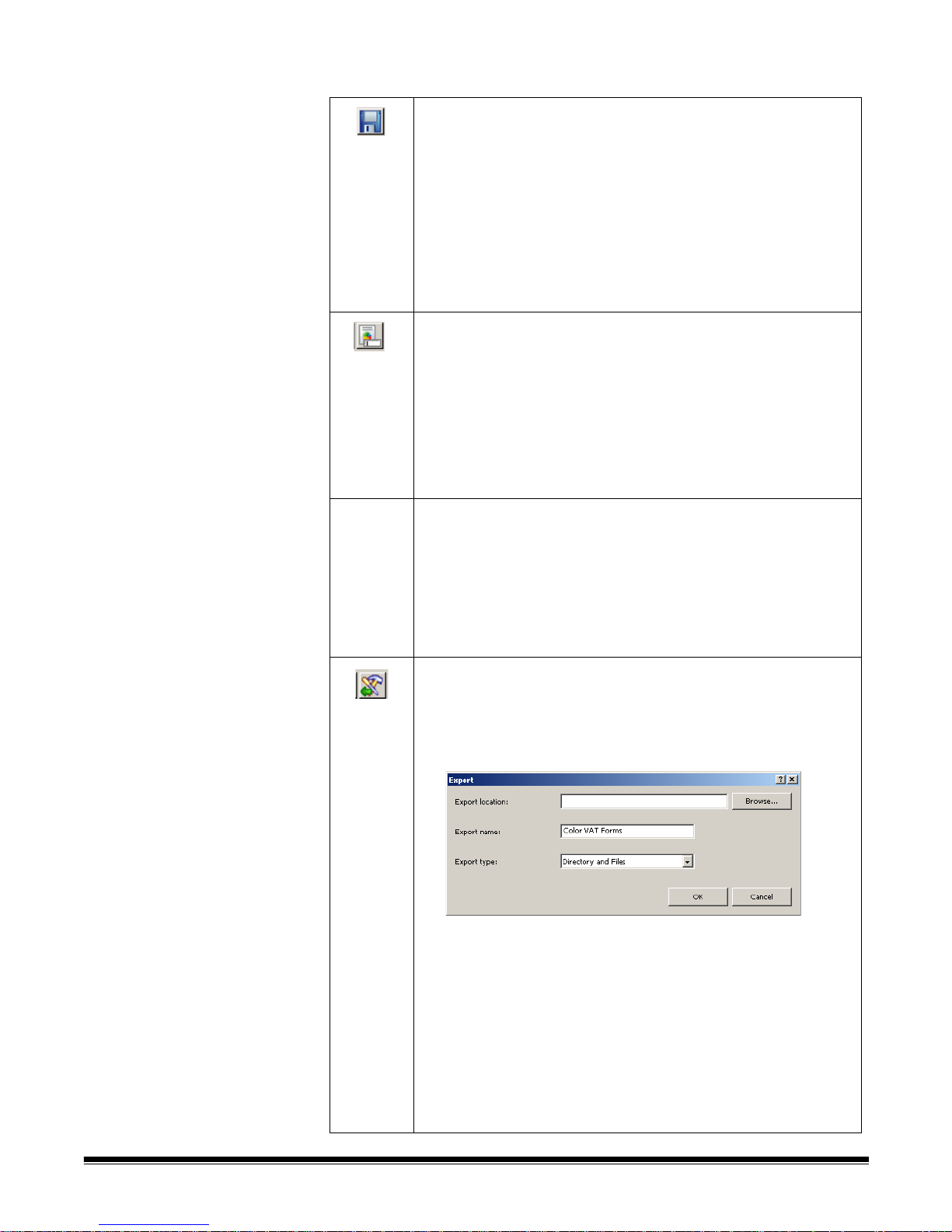
Icons
Add: allows you to add a new job setup.
1. Click the New icon.
2. Enter a name for the new job setup and click Save.
3. Using the Capture, Index and Output tabs set up your
criteria for this job setup. See the sections that follow for
detailed information about each of these tabs.
4. Click OK when finished.
NOTE: The last character of the job setup name cannot be a
period (.).
Rename: allows you to rename the currently selected job setup.
You cannot rename a job that is open.
1. Select a job setup you want to rename from the Job Name
drop-down list.
2. Click the Rename icon.
3. Enter a new name for the job setup and click OK.
NOTE: The last character of the job setup name cannot be a
period (.)
Delete: allows you to delete the selected job setup. You cannot
delete a job setup if it is open, or until all batches are processed
or deleted.
1. Select a job setup you want to delete from the Job Name
drop-down list.
2. Click the Delete icon. A confirmation box will be displayed.
3. Click Yes to confirm the deletion.
Export: allows you to export the job setup to a different location
while still saving it in Capture Pro Software.
1. Select a job setup from the Job Name drop-down list.
2. Click the Export icon. The Export dialog box will be
displayed.
3. Click Browse to navigate to the destination folder where you
want the job setup exported.
4. The export name will be filled in with the job name that you
are exporting. If you want to change that name, enter the
new name in the Export name field.
NOTE: Directory and Files is the only Export type available at
this time.
4-4 A-61635 December 2010
5. Click OK. A message will be displayed to notify you that the
export was successful.
Page 53
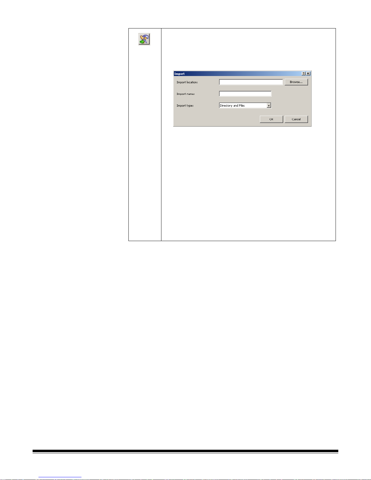
Import: displays the Import Job dialog box, which allows you to
import a job setup into Kodak Capture Pro Software from
another location.
1. Click the Import icon. The Import dialog box will be
displayed.
2. Click Browse to navigate to an exported job setup you want
to import.
3. The import name will be filled in with the job name that you
are importing. If you want to change that name, enter the
new name in the Import name field.
NOTE: Directory and Files is the only Import type available
at this time.
4. Click OK. A message will be displayed to notify you that the
import was successful.
NOTE: If you are importing a job that uses a different scanner
model than the one you are using, any scanner -spe c ific
settings (i.e., printer/counter settings) must be
reconfigured.
After making all your job setup entries, click:
OK — closes the dialog box. All the entries you made are saved.
Cancel — closes the dialog box. Your entries are not saved.
Apply — saves the changes made in the dialog box. The dialog box remains
open.
A-61635 December 2010 4-5
Page 54
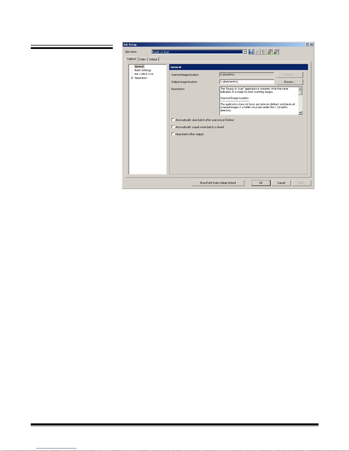
Job Setup:
Capture tab
The Capture tab allows you to make General, Batch, Bar Code & OCR,
Separation and Scanner settings.
• General — allows you to define the way images will be stored after
scanning.
• Batch Settings — allows you to define the batch name format for the job
setup and put limits on the numbers of batch documents or document
pages.
• Bar Code & OCR — allows you to create and modify bar code and OC R
zones and set them up for use.
• Separation — allows you to set up batch and document separations by:
count, blank page, bar code zone, OCR zone, or patch code.
• Scanner — allows you to create settings for image addressing and printing
on scanners with those capabilities. Scanner settings such as image
address, printer , and patch settings should always be done in Job Setup and
not in Page Setup. Conflicting settings will default to Job Setup settings.
4-6 A-61635 December 2010
Page 55

General settings Capture tab
Select General on the Capture tab to make or change the following settings:
Scanned image location — displays the current location where scanned
images will be stored for the selected job. If you do not want images scanned
into the displayed location, click Browse to select another location.
Output image location — allows you to select the final destination for your
output images. If you do not want the images to go to the displayed location,
click Browse to select another location.
Description — allows you to enter any important notes as a reminder of the
settings for this job setup.
Automatically close batch after scanning is finished — if checked, closes
the batch in Batch Explorer and the Image Viewer when the scanner transport
stops.
Automatically output when batch is closed — if checked, processes the
batch to output immediately after the batch is closed.
Keep batch after output — if checke d, saves the batch in the scanned im age
location and also creates the output batch.
A-61635 December 2010 4-7
Page 56
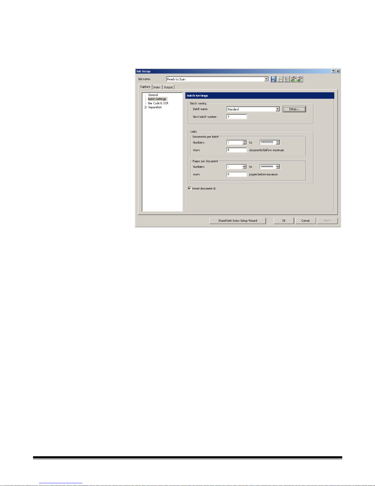
Batch settings —
Capture tab
Select Batch Settings on the Capture tab to define the batch naming format
for this job and set limits on the number of batch documents or document
pages. For example, if you know that all of your batches contain 100
documents, setting limits will alert you if your batch does not match the number
of documents you are expecting in a batch.
• Batch naming — make the following selections:
- Batch name — select a batch name from the drop-down list. The
Standard batch name is “BatchXXX”. If you want to change your batch
name to “Invoices” and the date, you would click Setup to open the
Standard Setup dialog box. From this dialog box, you can make these
settings. See the next section “Changing the Batch nam ing setting s” for
procedures.
- Next batch number — enter the desired next batch number.
The actual batch number is determined at the time the batch is created.
You will not be able to enter a value if Enable Job Level batch
numbering is unchecked. See “Setting up your Workstation” in Chapter
3.
- Limits - Documents per Batch — make the following selections:
- Numbers: enter or select the minimum and maximum number of
documents that you want to allow in a batch.
- Warn: enter a document number to serve as a warning that the batch is
approaching its maximum number of documents. When scanning
exceeds this limit (by one or two documents), scanning will stop.
• Limits - Pages per Document — make the following settings:
- Numbers: enter or select the minimum and maximum number of pages
that you want to allow in a document.
- Warn: enter a page number to serve as a warning that the document is
approaching its maximum number of pag es. When scanning exceeds this
limit (by one or two pages), scanning will stop.
• Reset document ID: check this box to reset the document counter to 0.
4-8 A-61635 December 2010
Page 57
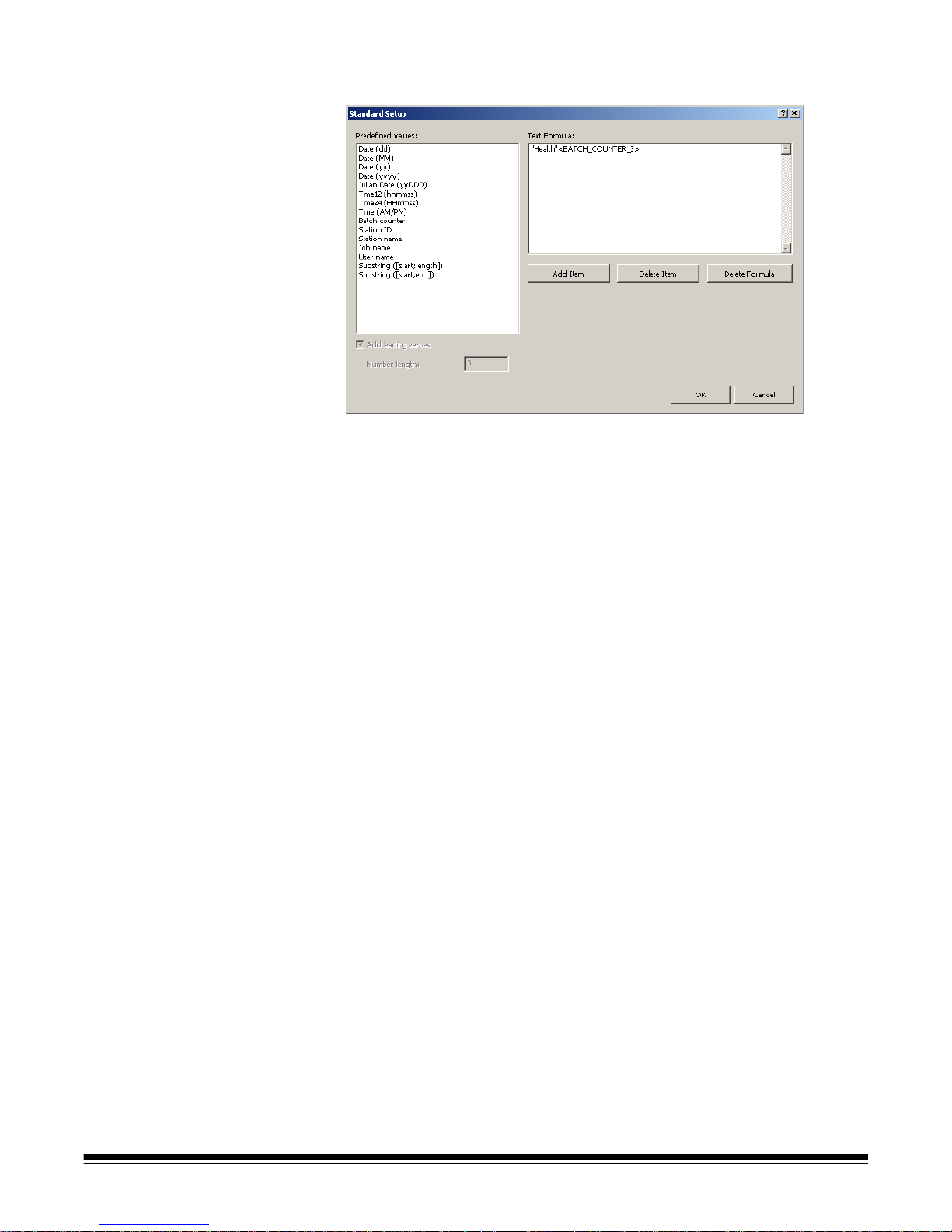
Changing the Batch naming
settings
When you select Setup from the Batch naming box, the Standard Setup dialog
box will be displayed where you can add or delete values to the batch name.
The Predefined values list provides values that you can select to add to the
text formula currently in use. You can add any number of items to the batch
name by selecting the item you want from the Predefined values list.
For example, if you want your batch to be labeled with the User name, date
and time you would enter the following:
User name, Date (dd), Date (yy), Time24 (HHmmss)
The result would be: John Smith0409115503.
To add a value:
1. Select the value you want to add from the Predefined values list.
2. Click Add Item. The item will be added to the formula.
NOTE: When specifying a path name, the limit is 248 characters in length .
3. If you want to add more values, repeat Steps 1 and 2.
NOTE: The Add leading zeros and Number length fields become available
when you select the Batch counter value.
4. If applicable, click Add leading zeros to add zeroes the left side of your
sequence number.
5. If applicable, enter a value in the Number length field to limit the numb er of
Predefined values allowed in the text formula.
6. Click OK when finished.
NOTES:
• Clicking Delete Item will remove the last predefined value from the text
formula.
• Clicking Delete Formula will remove the text formula.
Bar Code & OCR settings
— Capture tab
A-61635 December 2010 4-9
See Chapter 6, Bar Code and OCR Setup for information on configuring your
bar code and OCR settings.
Page 58

Separation settings —
Capture tab
By Count The By Count separation setting on the Capture tab allows you to enter the
The Separation option o n the Capture t ab a llows you to identify how you want
to separate batches and document s for this job . There are several wa ys to add
separators to your batches. The following list provides the op tions you can use
to create separation settings in Kodak Capture Pro Software:
• with a bar code zone (see Chapter 6, Bar Code and OCR Setup)
• with an OCR zone (see Chapter 6, Bar Code and OCR Setup)
• with Patch codes 2, 3 or T (see Chapter 5, Patch Code Setup)
• by automatically counting pages in a document(s) in a batch (set this option
up using the By Count option)
• with a blank page (set this option up using the By Blank Page option)
• by selecting Document>New or Batch>Next
• by pressing Enter during scanning
• by right-clicking on a page file in the Batch Explorer and clicking Split
The sections that follow provide information and procedures for using Kodak
Capture Pro Software to automatically separate documents or batches by
counting pages and how to use blank page separation.
number of documents that each batch will contain, and the number of pages
each document will contain.
1. Choose Batch Level and/or Document Level.
2. Click Every at the Batch Level and enter the number of documents that
the batch must contain before a new batch is created.
4-10 A-61635 December 2010
3. Click Every at the Document Level and enter the number of pages that a
document must contain before a new document is created.
Page 59

By Blank page When scanning images, you can insert blank pages to serve as separators.
Kodak Capture Pro Software can recognize blank pa ges and use them to start
new batches, start new documents, or create attachments to documents.
To use this method enable the By blank page option and select the desired
settings.
When you are simultaneously scanning black and white and color/grayscale
images, Capture Pro Software can use either black and white or the color
image to determine a blank page. When the software detect s a blank p age , all
four images (Color front; Color back; Black and White front; and Black and
White back) of the page are either deleted or attached to the new/current
document, depending on the settings you created.
The size (in bytes) of both the front and rear images of a page must fall below
the entered byte value for Capture Pro Software to recognize the page as
blank. If the software does not recognize a blank page, it will ignore it as a
separator.
NOTE: It is recommended that you test these values to ensure that the
software will detect your blank pages as a separator. See the next
section “Testing your settings” for procedures.
Blank Page Image Separator when — activates blank page separation.
• Image size (byte) is below — creates blank page separations based on the
size (in bytes) of the blank page image. Specify the maximum amount of
data (bytes) an image can contain and still be considered blank for each
image type (Black & White, Color/Grayscale) that you will be scanning.
The image size is checked against the raw image coming from the scanner
before operations are perfor me d .
- Black and White: enter the maximum image size in bytes for bl ack and
white. By default, 3000 bytes is suggested for black and white images.
A-61635 December 2010 4-11
- Color/Grayscale: enter the maximum image size in bytes for color or
grayscale. The maximum image size that can be specified is 1,000,000
bytes (1 MB) to allow for blank page separation when color scanning.
100,000 bytes is recommended.
Page 60

• Image content (%) is below — creates blank page separations based on
the percentage of image content in the blank page image.
NOTE: If the pages you will scan are different sizes, a small page may fall
below your blank image byte count even though it contains data.
In this case, you may prefer to describe a blank image by
specifying % content rather than byte size.
- Black & White: enter the percentage limit for black and white images.
- Color/Grayscale: enter the percentage limit for color and grayscale
images.
Test — opens the Test Image dialog box, which allows you to scan and test
the blank page that is being used as a separator that will be considered blank
when compared against the Image content (%) settings. Use this option to
verify that the software considers the page to be blank. See the next section
“Testing your settings” for more information.
What to do if a page is blank — select one of the options as the next step
after the software recognizes a blank page separation.
• Create a new batch — creates a new batch when a blank p age is detected.
• Create a new document — creates a new document whe n a bl ank page is
detected.
• Next page stays in current document — deletes the blank page.
• Delete page — when checked, the blank page will not be included in the
batch or document that you are separating on.
Testing your settings 1. Place a document in the scanner that is representative of the document
you want to test for blank page separation.
2. Click Test to display the Test Image dialog box.
The results will be displayed in the Test result box.
• The image is: indicates if the image is Blank or Not Blank.
• Image size is - (bytes): the size of the test image in bytes.
• Content is - %: the percentage of content in the test image.
4-12 A-61635 December 2010
3. Evaluate the values displayed in the Image size is - (bytes) and/or
Content is - % test result area and click Close.
4. Based on the results, readjust your entered values as needed and click
OK.
Page 61

Job Setup:
Index tab
Indexing is a sophisticated feature that allows you to add data processing
functions to your scanning, capturing and outputting of images at the
document and batch level.
You can set up indexing formulas that check the accuracy of metadata
contained in OCR zones and bar code zones. If OCR or barcode reading
misinterprets data, the indexing formula can catch the errors and stop the
scan.
You can setup indexing formulas that output your images to different locations
based on metadata.
• For information on creating input formats, see “Input formats” later in this
section.
• For information on creating output formats, see “Output format s” later in this
section.
• For information on setting up indexes for output to SharePoint, see “Using
the SharePoint Index Setup Wizard” later in this section.
The Index tab on the Job Setup dialog box allows you to define an index field
at the Batch level and Document level. Index fields are setup the same way
for Batch level and Document level.
Following are descriptions of the fields on the Index tab:
A-61635 December 2010 4-13
Action when audit fails — select the action you want the scanner to take
when an audit fails.
• Continue scanning: keep scanning even when the audit finds illegal index
values.
• Stop scanning: stop scanning and automatically enter Index Editing mode
when the audit finds illegal index values.
Page 62

Bypass audit during navigation — when checked, disables the audit
function when navigating through docu men ts in the Batch Exp lor er. The term
"audit" refers to the verification system that verifies all index values comply
with the input/output format.
The Indexes field displays the values that are set up for each index: Name,
T ype, Default V alue , Input Format, Output Format , Read-only , and Hidden.
Y o u can edit, delete, move a value up or down in the list or add a new value by
using the following buttons:
• Add: opens the Document Add Index Field dialog box to create a ne w index
field in a document or the Batch Add Index Field dialog box to create a new
field in a batch.
• Edit: opens the Document Edit Index Field dialog box to modify an index
field in a document or the Batch Edit Index Field dialog box to modify an
index field in a batch.
• Delete: click to remove the selected index field.
• Move up: click to move the selected index field up one position in the index
list.
• Move down: click to move the selected index field down one position in the
index list.
Adding a document
index field
To add a document index field:
1. Select File>Job Setup. The Job Setup dialog box will be displayed.
2. Select a job from the Job Name drop-down list and open the Index tab.
3. Open the Document tab.
4. Click Add. The Document Add Index Field dialog box will be displayed.
4-14 A-61635 December 2010
5. Enter the name of your index in the Label field.
6. Enter any notes or comments in the Description field.
Page 63

7. Select either Single Value, Drop-down list, Drop-down list, multiple
selection or an index API (if available) from the Type field. Single Value
allows to you enter any value. Drop-down list allows you to set up a fixed
list of values to choose from (e.g., if you want to provide a list of countries
to choose from).
NOTE: If you created your own index API it will appear in the Type drop-
down list. When you select an index API, the Setup button will
become available. Click the Setup button to make any
configuration changes.
8. If you selected Single V alue, you can check Read only to make this inde x
non-writable. This protects crucial information from being deleted by
operators.
9. Check Required to make this index a must-have check item.
10. If you selected Single Value, you can check Hidden to hide this index
from users. This protects sensitive information.
11. Enter a number to define the shortest valid length of the index field in the
Minimum index field length field.
12. Check the Check field during scanning box if you want the system to
check index fields when scanning pages.
13. Enter a predefined value in the Default value field or click Setup to display
the Default Value Setup dialog box.
A-61635 December 2010 4-15
NOTE: If you created a bar code or OCR zone, it will be displayed in the
Predefined values list (e.g., BC_[zonename] or OCR_[zonename].
To use a bar code/OCR zone for an Index field, you must assign
the appropriate BC_[zonename]/OCR_[zonename] as a default
value for the Index field. You may need to scroll to the bottom of
the Predefined value list to see the Bar code/OCR index fields.
Page 64

Use the Default V alue Setup dialog box to cr eate or revise a form ula for the
default value of the index field.
• Select a predefined value from the Predefined Values list. The Default
Value Formula (if any) will be displayed on the right side of the box.
• Click Add Item.
NOTE: Delete Item removes the last predefined value that was added
to the Default Value Formula; Delete Formula removes the
entire Default Value Formula.
• Click OK when finished. The revised formula will be populated into the
Default Value text box.
14. Enter your input format. See the section entitled “Input for mats” later in this
chapter for more information.
15. Enter your output format. See the section entitled “Output formats” later in
this chapter for more information.
16. If you want to define Substitute Characters, click Setup to define
character pairs for automatic substitution. The Substitute Chara cters Setup
dialog box will be displayed.
4-16 A-61635 December 2010
• Original column — lists the old characters to be replaced. Select an
original character from the drop-down list at the bottom of the column.
Select <Space>, <Linefeed> or <Tab>. An original character can appear
only once in the Original column.
• Substitute column — lists the new characters to be put in. Select a
substitute character from the drop-down list at the bottom of the column.
Select <Space>, <Linefeed>, <Tab> or <Replace>. A substitute
character may appear more than once in the Substitute column.
• Add — click to add the original and substitute character pair that you
selected from the two drop-down lists. If you only selected an original
character, Kodak Capture Pro Software will default to <Replace> as the
substitute character.
• Delete — deletes the highlighted original and substitute character pair
from the Original and Substitute columns.
Page 65
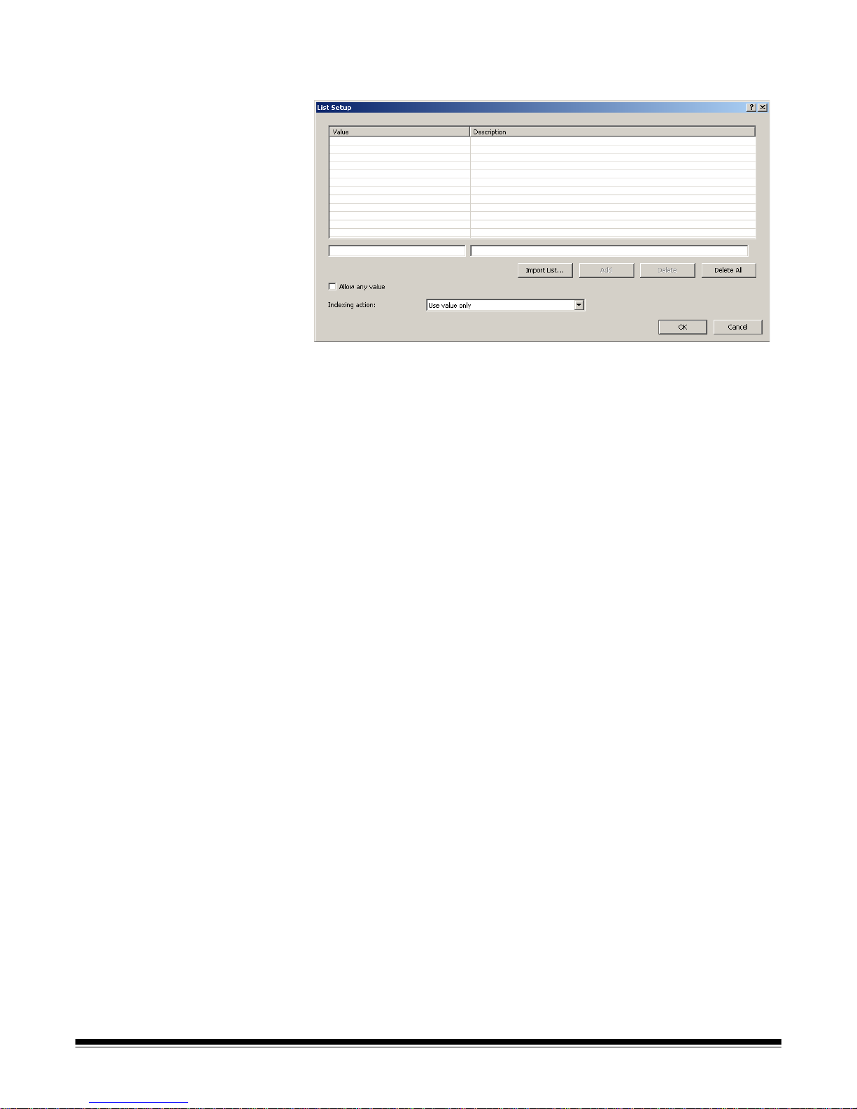
17. If you want to define a value list for the index field, click Setup next to the
List box. The List Setup dialog box will be displayed.
You can select to manually enter list values or import a list of existing
values from an ODBC compliant data source or a SharePoint library.
Manual entry
• Enter the desired value in the text box under the Value column.
• Enter a description of the value in the text box under the Description
column.
• Click Add to add the value and description pair that you entered in the
two text fields. If you did not create a description, that row in the
Description column will be blank.
Importing a list
• Click Import List.
• Create a new SharePoint or ODBC connection or select and existing
connection.
• Click Next.
• Select the column that will be used to populate the Value field and
select a column that will be used to populate the Description field.
A-61635 December 2010 4-17
Page 66

• Click Import. All unique values and the associated descriptions, if
specified, will be imported. If a matching value is already in the list, it will
not be replaced by the imported value. Imported values will be
appended to the list.
NOTE: Click Delete if you want to remove a value or click De lete Al l to
delete all entries in the list.
•Check Allow any value if you want to set no limitation on index values.
• Select an Indexing action from the drop-down list: Use value only , Use
description only or Use value and description.
• Click OK when finished and return to the Document Add Index Field
dialog box.
18. Click OK on the Document Add In dex Field dialog box. The new document
index information will be displayed in the table in the Document tab.
NOTE: To sort the table in ascending or descending order, click on the
appropriate column header. If you click on the Value column
header, the table will be sorted by the values in the Value column.
If you click on the Description column header, the table will be
sorted by the values in the Description column.
19. Click OK to save and exit the Job Setup dialog box.
4-18 A-61635 December 2010
Page 67
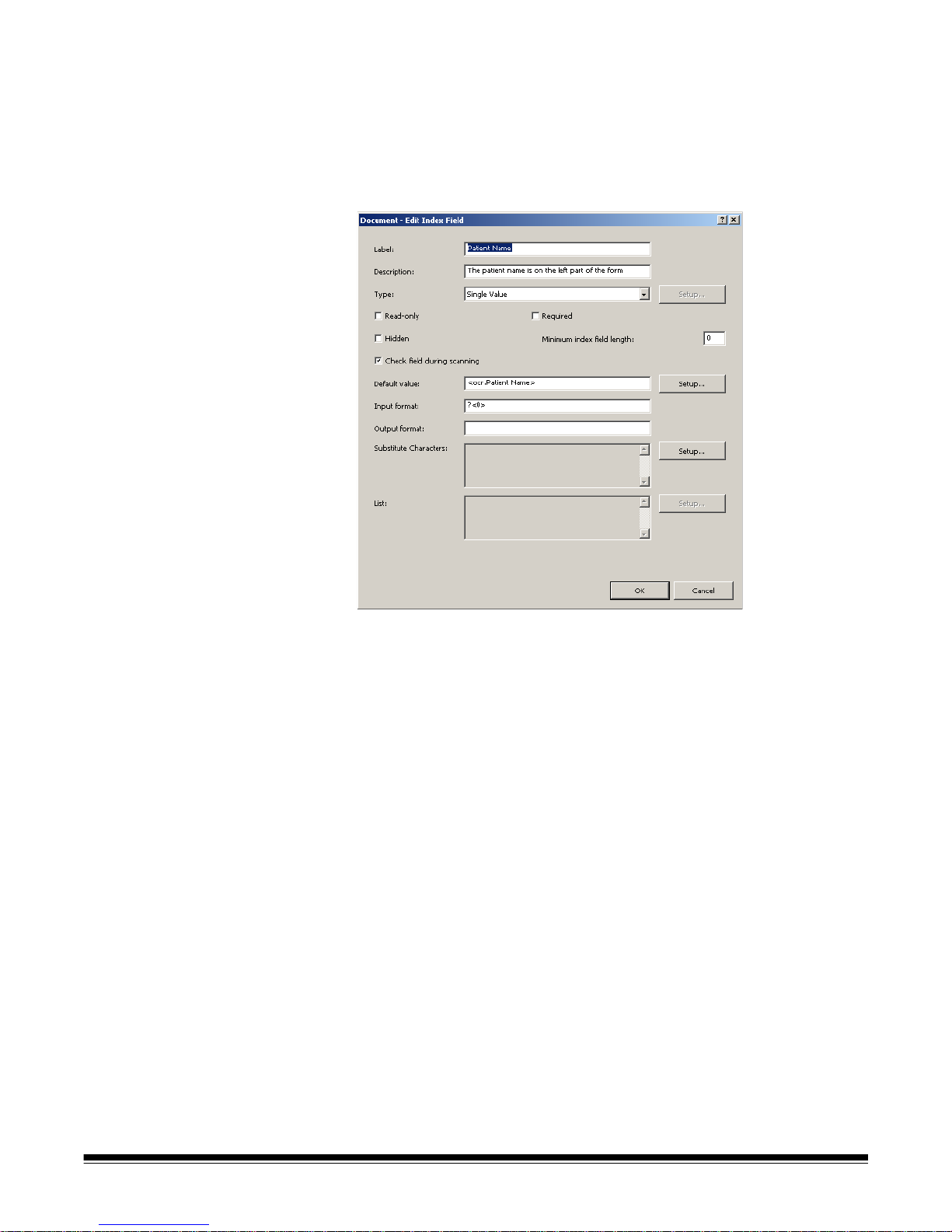
Editing a document
index field
To edit a document index field:
1. Select File>Job Setup. The Job Setup dialog box will be displayed.
2. Select a job from the Job Name drop-down list and open the Index tab.
3. Open the Document tab.
4. Click Edit. The Document Edit Index Field dialog box will be displayed.
5. Change the information in the dialog box as desired and click OK.
A-61635 December 2010 4-19
Page 68
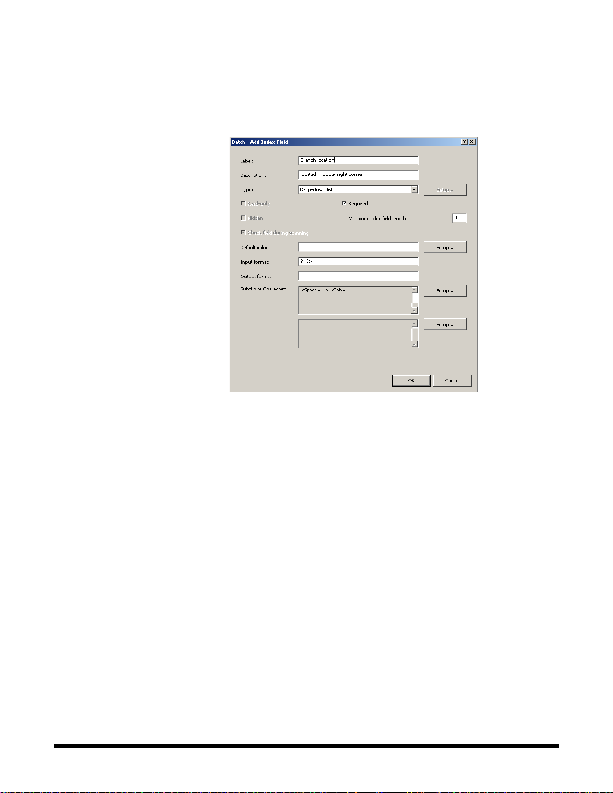
Adding a batch index
field
To add a batch index field:
1. Select File>Job Setup. The Job Setup dialog box will be displayed.
2. Select a job from the Job Name drop-down list and open the Index tab.
3. Open the Batch tab.
4. Click Add. The Batch Add Index Field dialog box will be displayed.
5. Complete the information in the dialog box and click OK. See the section
entitled, “Adding a document index field” earlier in this chapter for detailed
field descriptions.
6. Click OK to save and exit the Job Setup dialog box.
4-20 A-61635 December 2010
Page 69

Input formats An Input Format is a text expression used to audit the user input for a
particular index field. Its purpose is to prevent incorrect data from being
entered into index fields. The syntax of the input format can be one or
combination of the following formats:
• Text formats
• Number formats
• Time format s
• Fixed string formats
Input Tex t formats #
#<maxlength>
#<minlength, maxlength>
# — used to represent a single character of a specific type. # may be one of
the following character types:
9: valid input character set includes '0', '1', ..., '9'
Z: valid input character set includes 'A', 'B', ..., 'Z'
z: valid input character set includes 'a', 'b', ..., 'z'
A: valid input character set includes all characters in Z and z type
C: valid input character set includes all characters in Z and 9 type
c: valid input character set includes all characters in z and 9 type
X: valid input character set includes all characters in Z, z and 9 type
?: valid input character set includes any characters
Examples
999999
Description — 6 numeric characters
Valid input examples
123456
888888
Invalid input examples
ABCDEF wrong character type
1234567 too long
12345 too short
ZZZ999?
Description — 7 characters, first three characters are alphabetic letters, next
three characters are numeric, last character is any character.
Valid input examples
BAT001%
BOX123a
Invalid input examples
BAT12b3 sixth character must be a numeric
Bat123a second and third letters must be upper case alphabetic
characters
BAT12345 too long
A-61635 December 2010 4-21
Page 70

#<maxlength> — used to represent a variable length text value that has n o
minimum length but may have a maximum leng th.
• If maxlength is 0, there is no limitation on the length of the inp ut value.
• If maxlength is greater than 0, the length of the input value length must be
less than or equal to maxlength.
The maxlength may not be less than 0.
Examples
A<6>
Description — a string that may contain 6 or less alphabetic characters.
Valid input examples
A
ABCDEF
Invalid input examples
ABC123 last three characters must be alphabetic characters
ABCDEFG too long
?<0>
Description – any text value.
#<minlength, maxlength> — used to represent a fixed or variable length
input value that may have a minimum and maximum length.
•If minlength is 0, the input string may be empty.
•If minlength is greater than 0, the input value length must greater than or
equal to minlength.
•The minlength may not be less than 0.
•If minlength is equal to maxlength, the input value must have the specified
number of characters.
Examples
X<2,10>
Description — an input value that contains 2 to 10, upper or lower case
alphabetic or numeric characters.
Valid input examples
Batch0001
1234abcABC
A1
Invalid input examples
Batch-001 The ‘-‘ character is not a valid ‘X’ character
A too short
1234abcdABCD too long
AB Inc space character is not a valid ‘X’ character
4-22 A-61635 December 2010
Page 71

Input Number formats #
?<3,0>
Description – a string that contains 3 or more characters of any type
Valid input examples
ABC
+%=
ABC Company
jsmith@ABC.com
Invalid input examples
A1 too short
A<4,4>
Description — a string of exactly 4 alphabetic characters. The same format as
AAAA.
9<0,3>
Description — a string of 3 or less numeric characters. String may be empty.
A<3,2>
Description — invalid input format, maxlength must be greater or equal to
minlength if maxlength is greater than 0.
#(min, max)
#(min, max]
#[min, max}
#[min, max]
# — used to represent one of the following number types:
i : integer number that may be positive or negative, does not cont ain a decimal
point
n : any number, positive or negative and may contain a decimal point.
The value range or precision of the number is limited by the operating system.
The valid number range is typically:
i : -2,147,483,648 to 2,147,483,647
n : 1.7 E +/- 308 ( 15 digits )
The min and max values define the range of the number value.
The value of min and max must be consistent with the number type. For
example if the number type is i, both min and max must be a valid integer
number.
The character * may be used in place of min or max and represents an infinite
value or no limit.
The max value must be greater or equal to the min value.
( : input value must be greater than min.
) : input value must be less than max.
[ : input value must be greater than or equal to min.
] : input value must be less than or equal to max.
A-61635 December 2010 4-23
Page 72

Examples
i
Description — any integer number.
Valid input examples
123
-456
Invalid input examples
123.456 must be integer. Decimal values are not allowed
-123. integer values cannot have a decimal point
n
Description – any integer or decimal number
Valid input examples
123
123.456
-123.
#(min, max) — used to specify a value that is greater than min and less than
max.
Examples
i(-100, 100)
Description — any integer number greater than –100 and less than 100
Valid input examples
-99
0
99
Invalid input examples
-100 too small, must be greater than –100
-99.9 must be an integer (decimal not allowed)
100 too large, must be less than 100
#(min, max] — used to specify a value that is greater than min and less than
or equal to max.
Examples
i(-100, 100]
Description — any integer number greater than –100 and less than or equal
to 100
Valid input examples
-99
0
100
Invalid input examples
-100 too small, must be greater than –100
-99.9 must be an integer (decimal not allowed)
101 too large, must be less than or equal to 100
4-24 A-61635 December 2010
Page 73

#[min, max) — used to specify a value that is greater than or equal to min
and less than max.
Examples
n[-100, 100)
Description — any number greater than or equal to –100 and less than 100
Valid input examples
-100
-99.9
99.9999
Invalid input examples
-100.1 too small, must be greater than –100
100 too large, must be less than 100
#[min, max] — used to specify a value that is greater than or equal to min
and less than or equal to max.
Examples
n[-100, 100]
Description — any integer number greater than or equal to –100 and less
than or equal to 100
Valid input examples
-100
0
100
Invalid input examples
-100.1 too small, must be greater or equal to –100
100.001 too large, must be less than or equal to 100
i[100, *)
Description — any integer number greater than or equa l to 10 0
Valid input examples
100
1000
Invalid input examples
99 too small, must be greater than or equal to 100
100.5 integer values cannot have a decimal point
i(-1.0, +1.0)
Description — this is an invalid input format because the min and max are not
integer values as the “i” specifies.
n(+1.0, -1.0)
Description — this is an invalid input format because max is less than min.
A-61635 December 2010 4-25
Page 74

Input time formats T<timeformat>
timeformat is a text string expression of the date/time value. The syntax ca n be
one or combination of the following elements:
yyyy year (1000-9999)
yy year (00-99, for 00-79, it means 2000-2079, for 80-99, it means
MM month (01-12)
dd day of month (00-31, validate date when year and month are available)
DDD day of year (001-366, validate date when year and mo nth are available)
HH hour (00-23)
hh hour (01-12)
mm minute (00-59)
ss second (00-59)
TT AM/PM
T A/P
tt am/pm
t a/p
"text" text is a fixed text string.
The following date/time elements cannot be repeated in the timeformat. For
example, if you have selected yyyy for year date format, you cannot use yy o r
another yyyy in the timeformat. This limitation includes:
yyyy and yy
dd and DDD
HH and hh
HH, TT, T, tt and t
1980-1999)
Examples
T<yyyyMMdd>
Description — a full date.
Valid input examples
20051025
19000101
Invalid input examples
2005/10/25 unexpected character /
20051032 invalid date
20050229 invalid date (because the year 2005 was not a leap year)
00990101 date is earlier than 1000
4-26 A-61635 December 2010
Page 75

T<MMdd>
Description — a date without a year specified.
Valid input examples
1201
1231
0229
Invalid input examples
0001 invalid month
0230 invalid date of February regardless if it is a leap year
ABCDEF invalid text
T<HH":"mm":"ss>
Description — a time with : as separator.
Valid input examples
23:59:59
00:00:00
Invalid input examples
99:59:00 invalid hour
120000 no separator
T<hhmmsst>
Description — a full time.
Valid input examples
010000a
120000p
Invalid input examples
010000A A should be lower case
000000a invalid time
1355101 invalid hour must be 00-12
T<HHmmssTT>
Description — this is an invalid input format because HH represents 00 to 23
hours and TT represents AM/PM which is not valid with a 24-hour time string.
T<yyyyMMyyyy>
Description — this is an invalid input format for yyyy because it was used more
than once in a timeformat.
A-61635 December 2010 4-27
Page 76

Input fixed string formats “text”
text is any text string. Because the start and end of the text string is defined by
the character “ (double quote), the double quote cha racter is not allowed in the
text string. A text string format is normally used in combination with other input
formats.
Examples
999”-”99”-”999
Description — fixed string (to define a United States Social Security number)
"ID"
Description — fixed string.
Valid input examples
ID
Invalid input examples
XX does not match text in format. Input must be: ID
“Text”ABC””
Description — this is an invalid input format because it includes two extra “
characters in the format.
Combination input
formats
An Input Format can consist of multiple formats that are used in combination.
To use multiple formats to define an Input Format connect the format
expressions together with or without a blank space.
No format expression may follow format that is of variable length. For example:
A<1,0>”-Comment” is not valid because A<1,0> may be any length. The
format: “Comment-“A<1,0> is valid because the variable length format is at the
end of the combination input format.
Following are valid and invalid combination formats.
Examples
"ID"999999
Description — combined formats: "ID" and 999999.
Valid input examples
ID123456
Invalid input examples
IDabcdef the letters abcdef must be numbers
id123456 the first two letters id do not match format which is ID
“DATE”T<yyyyMMdd>
Description — combined formats “DATE” and T<yyyyMMdd>
T<“DATE”yyyyMMdd> is equivalent to the above format.
4-28 A-61635 December 2010
Valid input example
DATE20051025
Page 77

Invalid input examples
n?<0>
Description — this is an invalid input format for the number specified . n is a
variable length and no additional format can follow it.
A<2,3>”XX”
Description — this is an invalid input format because A<2,3> specified a
variable length and no additional format can follow it.
A<3,3>”XX”
Description — combined with formats: A<3,3> and “XX”.
Valid input example
XYZXX
Invalid input examples
XXXXXX unexpected X at the end of the text string.
20051025 the text DATE must proceed the date
DATE20051032 October does not have 32 days
XXXXXXX too long, extra X at end of string
A-61635 December 2010 4-29
Page 78

Index Default value
specification
Default value expression is a text expression to set the default value for a
particular index field. In default value expression, you need to define the
default value by using one or more predefined tags (i.e., system, barcod e/OCR
value) or a fixed string. You can also define multiple options of the default
value by connecting tags with the OR keyword.
Tags
<tagname>
<tagname:transformexpression>
tagname is a pre-defined system, OCR or barcode zone data expression.
System data expressions include date, time, Station ID and name, Job and
User name, batch and workgroup path, document an d p age ID and Last Value.
transformexpression is used to transform the format of the system or
barcode/OCR value. For example the date is expressed as MMddyy, the
transform expression may change the format to MM/dd/yyyy. See the next
section for a description of transform expression.
Fixed string formats "text"
text is a fixed text string. The string delimiter character " (double quote) is not
allowed in the format. A fixed text string format is normally used in combination
with other formats.
Using multiple tags A default value may include more than one tag expression used in
combination. For example you may want the Default value to include the date,
time and Station ID separated by a dash. To do this concatenate them
together.
For example:
<sys.date:ddMMyy>"-"<sys.time:hhmmss> "-“ <sys.stationid>
Using the OR keyword The OR keyword may also be included in the default value expression. This
may be useful when a value may not always be present. You may want to set
the default value to the value of a barcode that appears on the document.
For example:
<barcode.UPI ID Number>
If no barcode is found on the document, the index field will be empty. The OR
keyword can be used to provide an alternate value.
For example:
<barcode.UPI ID Number> OR “Barcode not found on document:”
<app.documentid>
As many expressions as needed may be OR’d
Default Value Option #1 OR Default Value Option #2 OR ... OR Default Value
Option #n
The system will check the Default Value Option # one by one from left to right,
and use the first valid data to initialize the index data.
4-30 A-61635 December 2010
Page 79

Available Tags — the following displays the available default value tags:
NOTE: Barcode/OCR zones will be displayed at the bottom of the default
value list.
Default value using
LASTVALUE
When lastvalue is selected as the default value, Capture Pro Software
automatically uses the last assigned value for an index field from the previous
document (for document indexes) or previous batch (for batch indexes)
whenever a new document or batch is created. This is useful, for example, in a
backlog application, when you scan folders of documents with the same date.
When you start scanning into a new batch, and no index value has yet to be
assigned, enter the date once and it remains the same for every new
document after that until you change it.
lastvalue is also very useful when performing bar code indexing but not every
document scanned will have a bar code attached to it. For example, a default
value expression of:
<barcode.Patient ID> OR <app.lastvalue>
means that when a new document is scanned, assign the index field value to
the value of the bar code zone "Patient ID" <barcode.Patient ID>. However, if
the document did not have a bar code on it, assign the index field instead to
the value of the previous document OR <app.lastvalue>.
A-61635 December 2010 4-31
Page 80

Transform Expressions A Transform Expression is a text expr ession to for mat or tran sfo rm the data of
a particular field into a default or output value. T ransform Expressions are used
to define default values and output format for an index field.
Default value specification: when a new batch or document is created, the
index field will be populated with a value based on the default value
specification. The default value specification is entered on the Index tab and
takes the form <tagna me> or <t agname:t ransform expression>. The transform
expression is described below.
Examples:
<sys.date:ddMMyy>
<sys.stationid:[1,5]>
Output format: when a batch is output, the index data for the batch and for
each document in the batch will be reformatted based on the output format.
For instance, a date index with a value of MMddyy can be reformatted to:
MM/dd/yyyy.
The output format is entered on the Index tab and takes the form:
transform expression.
Examples:
ddMMyy
[1, 5]
The syntax can be one or a combination of the following formats:
• Text formats
• Number formats
• Time formats
• Fixed string formats
Transform text formats [start]
[start, end]
[index, ‘delimiter’]
[start; len]
These formats are used to extract a sub-string from the original index value.
[start] — used to extract a sub-string starting at the position start to the end of
the original value.
• If start is a positive number, the start position will be counted from the
beginning of the original value.
• If start is a negative number, the start position will be counted from the end
of the original value.
• If start is 0 or *, the start position will be the beginning of the original value.
4-32 A-61635 December 2010
Page 81

Examples
[5]
th
Description — get sub-string from the 5
character to the end of the original
value.
“ABCDEFGHIJKL” Î “EFGHIJKL”
“1234567890” Î “567890”
“1234” Î “”
[*]
Description — get full string
“ABCEDFG” Î “ABCDEFG”
“1234567” Î “1234567”
[start, end] — used to extract a sub-string starting at the position start and
ending at the position end of the original value.
• If end is a positive number, the end position will be counted from the
beginning of the original value.
• If end is a negative number, the end position will be counted from the end of
the original value.
• If end is 0 or *, the end position will be the end the original value.
• If the start position is after the end position, the sub-string will have the
reverse order of the original value.
Examples
[1, 2]
Description — get sub-string from the 1
original value.
“ABCDEFG” Î “AB”
“123456” Î “12”
[-4, -1]
Description — get sub-string from the 4
character of the original value.
“ABCDEFGHIJK” Î “HIJK”
“1234567890” Î “7890”
[*, 5]
Description — get sub-string from the 1
original value.
“ABCDEFGHIJK” Î “ABCDE”
[5,2]
Description — get sub-string from the 5
of the original value.
“ABCDEFGHIJK” Î “EDCB”
st
character to the 2nd character of the
th
from the last character to the last
st
character to the 5th character of the
th
to the 2nd character in reverse order
A-61635 December 2010 4-33
“1234567890” Î “5432”
Page 82

[2, -2]
nd
Description — get sub-string from the 2
character to the 2nd from the last
character of the original value.
“ABCDEFGHIJ” Î “BCDEFGHI”
“1234567890” Î “23456789”
“AB” Î “BA”
“A” Î “A”
[index, ‘delimiter’] — used to extra ct th e ele m en t at th e po sitio n spec ifie d by
index where each element in the index data is separated by the character
delimiter. The first element is index 1.
NOTE: This transform expression is especially useful when assigning data
elements in a PDF417 bar code to different index fields. It is also
useful when assigning different lines of multi-line OCR results to
different index fields. The delimited produced by multi-line OCR is the
carat (^) character.
Examples
[2, ‘^’]
nd
Description — get the 2
element in the multi-line OCR where elements are
separated by the character ‘^’
“John Smith^123 Main Street^Some City” Î “123 Main Street”
[3, ‘*’]
Description — get the 3
rd
element from the PDF417 barcode where elements
are separated by the character ‘*’
“John Smith*123 Main Street*Some City” Î “Some City”
[start; len] – used to extract a sub-string for the position start for len
characters.
Examples
[2;3]
nd
Description — get sub-string from 2
character with a length of 3 characters.
“ABCDEFGHIJ” Î “BCD”
“1234567890” Î “234”
“AB” Î “B”
“A” Î “”
4-34 A-61635 December 2010
Page 83

Transform number
formats
#<width, fracwidth>
#<width, fracwidth, padding>
#<textformats, width, fracwidth>
#<textformats, width, fracwidth, padding>
0width
# can be one of the following characters to define the desired number type.
n: generic number
N: generic number with sign
p: percentage number
P: percentage number with sign
c: currency number
C: currency number with sign
The value range or precision of the number is limited by the operating system.
The valid number range is 1.7E ±308 (15 digits).
#<width, fracwidth> — used to format a number that has at most, width
number of characters and at most, fracwidth characters after the decimal.
width defines the total number of digits to be included in the output string.
• If width is a positive number , the output text will be right-aligned with the
padding character (if any) on the left.
• If width is a negative number, the output text will be left-aligned with the
padding character (if any) on the right.
fracwidth defines the number of digits to be displayed to the right of the
decimal point.
The number 0 is used to show no decimal point.
The * character is used to show a default of 6 digits to the right of the decimal
point.
Examples
n<20,2>
Description — a generic number with a maximum width of 20 characters and 2
digits after the decimal point. The string will be right aligned.
A-61635 December 2010 4-35
Page 84

Examples
“324.5” Î “ 324.50”
“abcd” Î “ 0.00”
p<-20, 2>
Description — a number expressed as a percentage with a total width of 20
characters and 2 digits after the decimal point. The string will be left aligned.
Examples
“0.12abc” Î “12.00% “
“-43” Δ-4300.00% “
c<20, 0>
Description — a number expressed as currency with a total width of 20
characters and no decimal point. The string will be right aligned.
Examples
“12345.6” Î “ 12,346”
“-12345.6” Î “ –12,346”
C<20, 2>
Description — a number expressed as signed currency with a total of 20
characters and 2 digits after the decimal point. The string will be right aligned.
Examples
“12345.6” Î “ +12,345.60”
“-12345.6” Î “ –12,345.60”
“abc” Î “ +0.00”
“-0.001” Î “ –0.00”
“-0.00” Î “ +0.00”
#<width, fracwid th, pa dding> — used to format a number that will be p added
with the padding character, to the specified width, including fracwidth
characters after the decimal point.
padding defines the character to fill the space if the formatted text is less that
the width defined.
Example
P<20, 3, ‘#’>
Description — a number expressed as a signed percentage with a total width
of 20 characters, 3 digits after the decimal point and p added with the character
‘#’.
Examples
“0.12abc” Î “############+12.0000%”
“-43” Î “##########-4300.000%”
#<textformats, width, fracwidth> — used to format a num ber that is
extracted from a string using textformats.
textformats specifies how to extract the number from the original index string.
See the Output formats section.
Example
N<[2], 20, 3>
Description — a signed number with a total width of 20 characters and 3 digit s
nd
after the decimal point. The number will be extracted starting at the 2
character in the original string.
4-36 A-61635 December 2010
Page 85

Examples
“A12345.6” Î ” +12345.600”
“-12345.6” Î “ +12345.600”
“TT9000” Î “ +0.000”
“—9999” Î “ –9999.000”
N<[2, ‘^’], 20, 3>
Description — a signed number with a total of 20 characters and 3 digits after
the decimal point. The number will be extracted from the 2 element in the
string, where the elements are separate d by the character ‘^’.
Example
“12345.6^45678.9” Î “ +45678.900”
#<textformats, width, fracwidth, padding> — used to format a number that
is extracted from a string using textformats and padded with the specified
character.
This format is a extension of the format #<textformats, width, fracwidth> where
the output string will be padded with the specified character.
0width — used to zero-fill a number to the minimum specified width.
Examples
010
Description — a zero-filled number with a total width of 10 characters.
Examples
“123” Î “0000000123”
“0” Î “0000000000”
03
Description — a zero-filled number with a total width of 3 characters.
Example
“1” Î “001”
“1234” Î “1234”
A-61635 December 2010 4-37
Page 86

Transform time formats #
# — may be one or any combination of the following formats:
yyyy year (1900-2099)
yy year (00-99)
y year
MM month (01-12)
M month (1-12)
dd day of month (01-31)
d day of month (1-31)
D day of week (1: Sunday, 2: Monday, etc.)
DDD day of year (001-365)
HH hour (00-23)
H hour (0-23)
hh hour (01-12)
h hour (1-12)
mm minute (00-59)
m minute (0-59)
ss second (00-59)
s second (0-59)
TT AM/PM
T A/P
tt am/pm
t a/p
ww week of year (01-53)
w week of year (1-53)
When using time formats, you must specify an Input Time format to define the
contents of the string that is to be formatted for output.
Examples
ddMMyyyy
Description — a date in day, month, year format.
Examples
Input Format: T<yyyyMMdd> the string “20051026” Î “26102005”
Input Format: T<yyyyMM> the string “102005” Î “102005”
4-38 A-61635 December 2010
Page 87

Fixed string formats text”
text is any text string. Because the start and end of the text string is defined by
the character “ (double quote), the double quote cha racter is not allowed in the
text string. A text string format is normally used in combination with other input
formats.
Examples
"ID-"[*]"-XX"
Description — output fixed text string of "ID".
Examples
"20051026" ==> "ID-20051026-XX"
Combining T ransform
formats
A Transform Expression can consist of multiple formats that are used in
combination. To use multiple formats to define a Transform Expression simply
connect the format expressions together with or without a blank space.
Examples
"Revenue"c<20, 2>
Description — combination with formats "Revenue" and c<20, 2>.
Examples
"123456" ==> "Revenue 123,456.00"
yyyy"/"MM"/"dd"-"HH":"mm":"ss
Description — combined with formats: yyyy , "/", MM, "/", dd, "-", HH, ":", mm, ":"
and ss.
Examples
"20051026080405PM" ==> "2005/10/26-20:04:05"
Input Format: T<yyyyMMddhhmmssTT>
Output formats An Output Format is a text expression to format the data of a particular index
field into an output value. Transform Expr essions are used to de fine the output
format for an index field.
Output format: when a batch is output, the index data for the batch and for
each document in the batch will be reformatted based on the output format.
For instance, a date index with a value of MMddyy can be reformatted to:
MM/dd/yyyy.
A-61635 December 2010 4-39
The syntax can be one or a combination of the following formats:
• Text formats — see Transform Expression, Text formats
• Number formats — see Transform Expression, Number formats
• Time formats — see Transform Expression, Time formats
• Fixed string formats — see Transform Expression, Fixed string formats
• Combination formats — see Transform Expression, Combining Tran sfor m
formats
Page 88
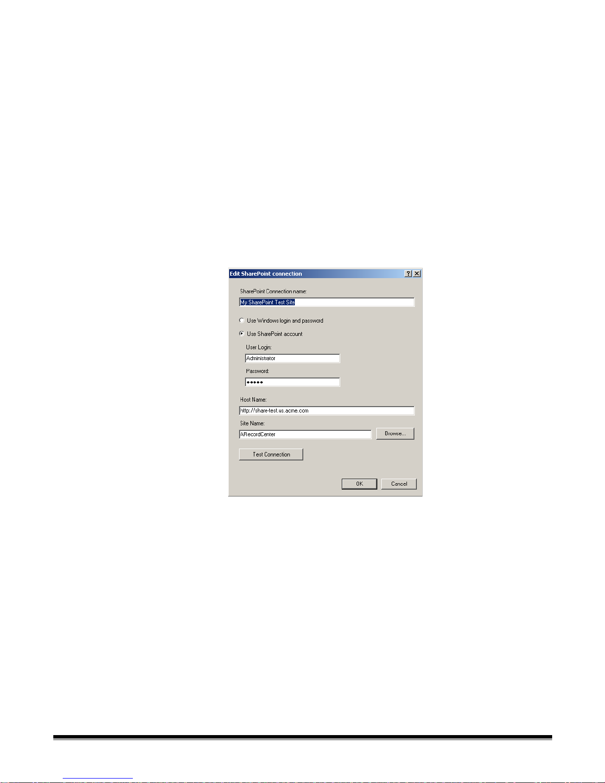
Using the SharePoint
Index Setup wizard
The SharePoint Index Setup provides a quick, easy way of configuring a
Capture Pro Software job setup for use with your existing SharePoint site.
The setup wizard will guide you in connecting to your SharePoint site, creating
index fields to populate SharePoint columns and defining storage paths for
images.
The wizard is aware of SharePoint data types and will recommend index field
formats to ensure properly formatted and ‘in range’ data capture. In the case
of columns of type ‘choice’, the wizard will populate a drop-down list with the
acceptable data values.
The SharePoint Index Setup Wizard will guide you through four steps:
Step 1: SharePoint setup: Create, Edit, Select SharePoint Connection
1. Select a ‘connection’ to the SharePoint site where you want to place the
batch images and data. A connection specifies the Host name, Site name
and the Credentials required to access the site. You may provide a
meaningful name to the connection for future use.
4-40 A-61635 December 2010
If no connections have been defined, the Create a SharePoint connection
dialog box will be displayed.
1. Enter a Host name for the connection. You will use this name to refer to
this specific SharePoint site.
2. Enter the credentials, if required, to access this SharePoint site.
3. Enter the Host name. For example: https://my-SharePoint-host.
4. Enter the Site name. If the host name and credentials are correct, you can
click Browse to select the available sites.
Page 89

Step 2. Creating Document Index Fields based on your existing
SharePoint columns
After selecting one of the available SharePoint Lists fo und on your Shar ePoint
site and selecting the Document Type, the SharePoint columns will be
displayed.
The Column Type will be shown and the Required checkbox will be checked if
the column is required by your SharePoint List.
By default the Create Index checkbox will be checked for all column types that
may be populated by the automatically created and configured index fields. If
you do not want to populate a specific column or if you do not require a new
Index field to populate a specific column, then uncheck the Create Index
checkbox. If you want to create an index field for a SharePoint column that is
not checked, check the Create Index check box and then click Edit to
configure the index field. You will have the opportunity later to specify the data
that is to be stored in a column.
As an example of when to uncheck the Create Index check box imagine that
the SharePoint column ‘Full Name’ is to contain a persons name in the form
‘last name, first name’.Two existing index fields, ‘First Name’ and ‘Last Name’,
will be used to populate this column. The mapping of these two index fields
will be done later, for now uncheck the Create Index checkbox for the ‘Full
Name’ column as an index field ‘Full Name’ is not needed.
An ‘Input Format’ will be recommended for each new index field based on the
data requirements of the SharePoint column. You should not need to change
the recommended format unless you need to further restrict the dat a range or
data type.
A ‘Default Value’ will be shown if a default value has been specified in
SharePoint for the column. Y o u may change an existing value or add a defa ult
value if a value is not shown simply be selecting the drop down list. A list of
default predefined values, including any defined bar code or OCR zones will
be displayed. If you require a more complex default value, select Edit. You will
be able to define the default value using one or more predefined tags or fixed
strings.
A-61635 December 2010 4-41
Page 90

The ‘Status’ column will indicate if there are any issues in creating an index
field. Selecting a row containing the indication will display a Status Message in
the area below the Edit button. This symbol indicates that an index field will
not be created for this SharePoint column. In most cases this is because the
column type may not be automatically created by the application. For example
the column type ‘calculated’ requires references to other SharePoint column
that are not known by the application. You may choose to create an index field
for this column by checking Create Index.
Selecting a row containing the indication will display a status message in
the area below the Edit button . Th e status me ssa ge will de scribe the problem
and how it may be resolved. This symbol indicates that there is a problem
creating the index field that must be resolved before continuing. You can
uncheck the Create Index check box if the index field is not needed.
To add or edit other index field parameters such as ‘Output fo rmat’, ‘Substitu te
Characters’ and ‘List’ (for drop down index fields) select the row for the
appropriate index field and click Edit.
Step 3. SharePoint setup: Selecting values to populate SharePoint
columns
Now that you have created index fields, you may use these index fields along
with system values (Job name, Batch name, date, time, etc.), OCR zone
values, Bar code zone values or combinations of these values to populate your
SharePoint columns.
4-42 A-61635 December 2010
The SharePoint columns that require a value are shown at the top. By default
the index field created in Step 2 is used to populate the column. To select a
different value, select the SharePoint column and select the change control
icon. Y ou can select one or more items from the list, including fixed text strings
enclosed in double quotes. For example "Created : "<DATE_DDMMYY>.
Any SharePoint column that was not included in Step 2 (Create Index
checkbox not checked) will not show a default value. This is because no index
field was created for this column. You may still define a value for this column
using other index fields, system values, OCR and bar code zone values or
combinations of these values.
Page 91

TIP: The SharePoint Name column will define the name of the file stored in
SharePoint. In Step 4 you will decide how to group images.
If you group by Multi-Page for each ‘Document’, then each document must
have a unique name. For example ‘Name’ may be
<DOCUMENT_SEQUENCENUMBER>.
If you group by Single page, each image must have a unique name which
means the Name column must contain a value that will be unique for each
image. For example ‘Name’ may be
<IMAGE_SEQUENCENUMBER_DOCUMENT>.
Step 4. SharePoint setup: Defining storage options and paths
The last step is to specify the format of the images and where you want to
store the images in SharePoint.
The ‘Starting Folder” is the path to an existing folder in the current SharePoint
site. The image paths you specify for ‘All’, ‘Black & White’ and ‘Color/
Grayscale’ will start at this folder. You may select Setup to view the available
folders.
If you have Black & White and Color / Grayscale images and all the images are
to be stored at the same location using the same image format then select the
All checkbox.
Select the file type (Text, TIFF, PDF, etc.) for your output. Select Options to
configure the file format for the file type you selected. For a description of the
file format dialog boxes see the section entitled “Setup options for File (1) and
File (2)” in Job Setup: Output Tab.
You may specify folder location for the image in the box below the file type.
Select Setup to build the folder location from available system and field index
values.
TIP: The Setup buttons allow you to specify the p ath and folder name in which
to store images (SharePoint documents). Each ‘document’ must have a
unique path and name or the document may be overwritten. If versioning is
configured, a duplicate filename error may result. Verify that SharePoint
‘Name’ you choose in Step 3 is compatible with the path and image grouping
selection you have made.
A-61635 December 2010 4-43
Page 92

If you only have Black & White or Color / Grayscale images or you would like to
have different file types for your Black & White and Color / Grayscale images
then select the ‘Black & White’ and ‘Color / Grayscale’ check boxes.
To check-in documents to a SharePoint document library that has versioning
enabled check the Check in after uploading check box. If your SharePoint
List does not have versioning enabled a warning will be displayed and the box
unchecked. Y ou may check-in documents with a major ver sion number (1.0) or
with a minor version number (0.1). If your SharePoint is not configured to allow
minor version numbering, a warning will be displayed and the major version
number selected.
TIP: When SharePoint versioning is enabled, you may also need to configure
SharePoint to ‘Require check out’.
When checking in, you may include a ‘Check In Comment’. The comment may
be a fixed message or click Setup to build a comment using system and index
values. For example: <STATION_NAME>" : " <USER_NAME>.
The predefined index called ‘Image Sequence number (batch)’ can start at a
specific number by checking the Continuous image numbering from
checkbox and providing a start value.
NOTE: Checking this box does not change the ‘Image Sequence number
(document)’ start value.
TIP: Before starting the wizard it is recom mended that cr eate any bar code and
OCR zones that you want to include in the output to SharePoint.
Launch the SharePoint Index Setup Wizard by:
• Selecting File>Job Setup, then select the SharePoint Index Setup Wizard
button at the bottom of the Job Setup dialog box.
4-44 A-61635 December 2010
Page 93

Index tab — Database
Lookup
Database Lookup can be used to populate or validate batch and document
index fields from ODBC (Open Database Connectivity) compliant data
sources. A configuration wizard is used to specify the data source, define how
the lookup is performed and what data is used to populate index files or
validate the contents of index fields. A Job Setup may contain more than one
Lookup. Each Lookup may be to a different data source and may be used to
populate or validate selected index fields. Lookups may occur during scanni ng
when the index value used for the Lookup is a result of a barcode reader or an
OCR action. Each Lookup takes the form: SELECT <table column 1>, <table
column 2>, ... <table column n> FROM <data source> WHERE <table column
x> = <index field value>.
Configuring Database
Lookup
Configuring Database Lookup starts with defining the batch and document
index fields that will be used by the Lookup. Database Lookups are configured
for each job.
NOTE: Defining of index fields in Job Setup has not changed from previous
versions of Kodak Capture Pro Software.
To add or edit a new lookup:
1. Click File>Job Setup. The Job Setup dialog box will be displayed.
2. Select a job setup from the Job Name drop-down list. The settings for the
job setup will be displayed.
3. Select the Index tab.
4. Select the Database Lookup tab. The Lookup s table will be displayed with
the following fields: Name, Input Index Field, Output Index Field (Batch)
and Output Index Field (Document) for each Lookup.
A-61635 December 2010 4-45
Page 94

5. Click Add. The Database Lookup wizard will be displayed.
6. Enter the name of your Lookup in the Lookup name field.
7. Click Browse to open the Select Data Source dialog box.
4-46 A-61635 December 2010
• Select an existing File Data Source or Machine Data Source, or click
New to create a new data sour ce. Depending on th e type of data so urce
you have selected, you will be prompted for additional information.
• Click OK after all required information has been entered.
8. Select the table or file from the Database table drop-down list that contains
the data that will be used to populate or validate the index fields.
Page 95

9. Click Next to define how you want to do the data lookup.
10. Select Validate index fields from Lookup results if you want to verify
one or more index field values match data in your data source.
11. Select Populate index fields from Lookup results if you want to fill in
one or more index fields from the Lookup.
12. Select the index field to be used by the Lookup as a key to find matching
values in the selected database from the Looku p index field drop-down list.
This list contains all defined document and batch index fields.
13. Select the table column to be searched for values matching the selected
Lookup index field from the Lookup table column drop-down list. This list
contains all table column names from the selected database table.
14. For each batch or document index field that you want to populate or
validate, select the database column that contains the desired data. Click
in the column to the right of the index field name and select the database
column from the drop-down list.
A-61635 December 2010 4-47
Page 96
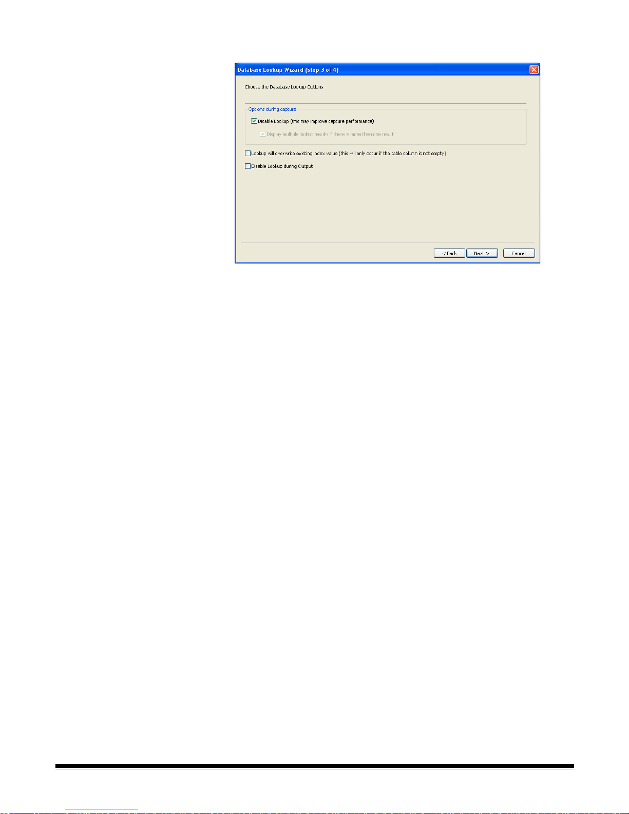
15. Click Next to choose the database lookup options.
16. Select the desired Lookup options:
• Disable Lookup: when checked, Lookups will not be performed during
scanning. This may improve performance with large or remote
databases. Lookups will continue to occur in Edit Index mode and when
the batch is output.
• Disable multiple lookup results if there is more than one result:
when checked, the Multiple Lookup Results table will not be displayed
during scanning. Multiple Lookup results will be resolved in Edit Index
mode, allowing scanning to continue uninte rr up te d.
• Lookup will overwrite existing index value: when checked, the
Lookup will always populate an index field with the lookup value in the
database, as long as the database entry has a value (i.e., is not empty
or null). If you want users to be able to manually enter data into an index
field that Database Lookup is populating, then this option should be
unchecked or disabled.
NOTE: Database Lookup will never overwrite data when the batch is
output.
• Disable Lookup during Output: when checked, no Lookup (populate
or validate) will occur during output. If unchecked, empty fields will be
populated and missing or multiple records will be ignored. V alidation will
fail if no matching record is found.
4-48 A-61635 December 2010
Page 97
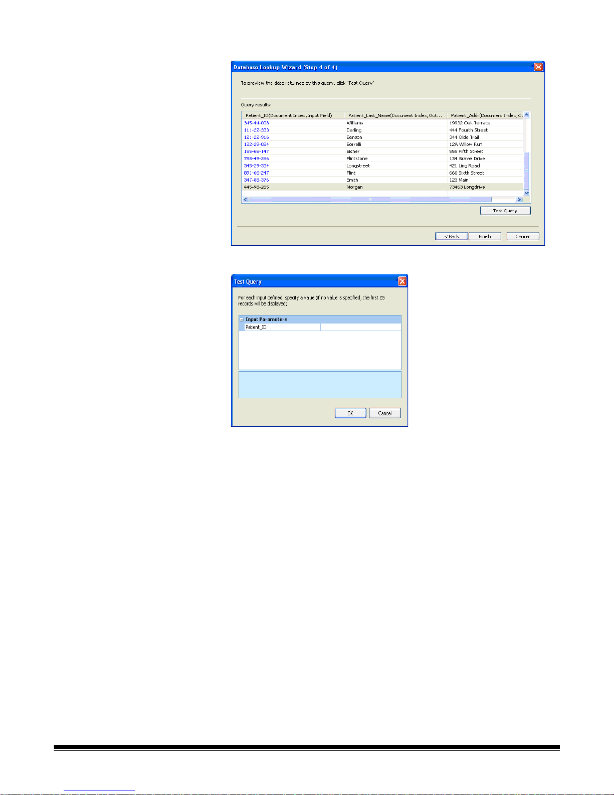
17. Click Next to test the Lookup.
18. Click Test Query. The Test Query dialog box will be displayed.
19. Enter a valid value for the parameter that is used to per form the Lo okup. If
you leave the value blank, the first 25 records in the data table will be
displayed.
20. Click OK
A-61635 December 2010 4-49
Page 98
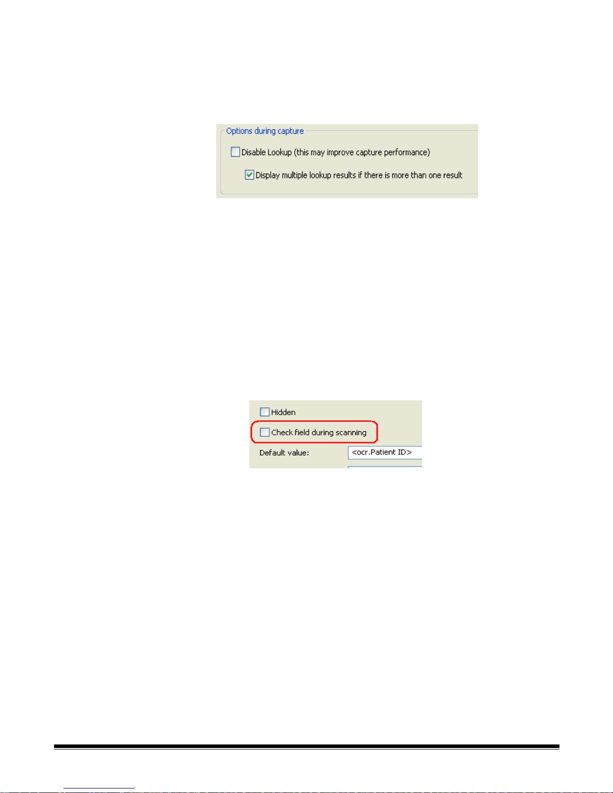
Using Database Lookup After configuring a job to do a Database Lookup , it is important to understand
when the Lookup will be performed. The following are the common scenarios:
During Scanning - Populating index fields
When Disable Lookup during capture has not been checked, Lookups will
occur on-the-fly during scanning.
The Lookup will only take place when the index field that is being used for the
Lookup has a value that was populated during scanning (e.g., as a result of a
bar code or zonal OCR read).
During Scanning - Validating index fields
When Disable Lookup during capture has not been checked, Lookups
configured for index field validation only will also occur on-the-fly during
scanning.
The Lookup Validation will only take place when the index field that is being
validated has a value that was populated during scanning (e.g., as a result of a
bar code or zonal OCR read).
NOTE: When Disable Lookup is not checked, Database Lookups will always
be performed during scanning. Even if the Index Field setup option
Check field during scanning is disabled, the database lookup va lidation
will still be performed.
4-50 A-61635 December 2010
Page 99
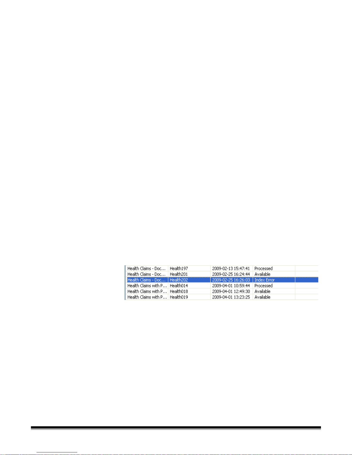
Edit Index mode After scanning has been performed and the user enters Index mode
(Index>Edit Index Fields), the Lookup will always be performed on a
document whenever the document is navigated to while in indexing mode.
If the index field that is being used for the Lookup already has a value (e.g.,
from bar code or zonal OCR) then the Lookup for a document will be
performed automatically when navigating to the document.
If data is manually being entered in the index field, then the Lookup will be
performed when the user leaves the index field. If the Tab key is used to
navigate away from the index field just entered, the results of populating the
other index fields will be displayed for verification. If the Enter key is used or
one of the other indexing mode function keys (i.e., F9, F10, F1 1) to navigate to
another document, then the Lookup will be performed and the other index
fields will be populated. However, you will not see the results of the Lookup as
that document is no longer being displayed in indexing mode.
If the Lookup index field is populated using Drag n’ Drop OCR, then the
Lookup will be performed immediately and the results of populating the other
index fields will be displayed for verification.
Batch Output Data base Lookup only occurs on output if the Disable Lookup on Output
option is not checked. When you click the Output tool, as part of Index field
validation, Database Lookup for populating and validating index fields is
performed immediately before the batch is queued for output processing. If a
Database Lookup is populating index fields, errors will be ignored. If no record
is found or multiple records are found, the current value in the index field will
be unchanged or left empty. If a Database Lookup is validating index fields, an
error will occur if no matching record is found. The batch will not be submitted
for output and the error must be corrected before the batch can be
successfully output.
If a batch is output from the Batch Manager screen or is automatically output
from Job Setup, Database Lookup is performed immediately as part of the
background batch processing. If a Lookup fails, the batch will be put into Index
Error status.
When the batch is opened to correct the error, the document that had the
Lookup failure will be automatically displayed and you can go into Index mode
to correct the indexing problem and re-submit the batch for output processing.
A-61635 December 2010 4-51
Page 100

Job Setup:
Output tab
The Output tab is where you set up your output options for your job setup.
• Destination — allows you to make settings for the format of the output,
where to send the output, and how to index it. The Destination options are:
- File (1) and File (2): allows you to select your file format (TIFF, JPEG ,
PDF, etc.) and type of output (e.g., black and white, color/grayscale).
- System (1) and System (2):allows you to select the System Output
Destination for your job setup.
- E-mail: allows you to setup up the software to automatically e-mail the
output.
- Print: allows you to setup up the software to automatically print the
output.
• Advanced Options — allows you to apply Kodak Capture Pro Software
image processing options to the output.
• Invoke Other Program — allows you to use another software application
on your output.
Destination options:
File (1) and File (2)
File (1) option — select a file format (TIFF, PDF, JPEG, etc.) for your output.
Your choice of formats will depend upon your type of output:
• All (black and white and color/grayscale)
• Black and white
• Color/grayscale
4-52 A-61635 December 2010
NOTE: For a description of the file format dialog boxes see the section
entitled, “Setup options for File (1) and File (2)” later in this chapter.
 Loading...