

Page 1
{ServiceManual}{Produ ction}{KodakServiceSupp ort}{ExternalAndInterna l}
Publication No. SM1399-1
SERVICE MANUAL
for the
Kodak EasyShare C643 ZOOM DIGITAL CAMERA
Service Code: 1399
and the
Kodak EasyShare C603 ZOOM DIGITAL CAMERA
Service Code: 1417
Important
Qualified service personnel must repair this equipment.
19JUN06
Confidential
Restricted Information
© Eastman Kodak Company, 2006
Page 2

PLEASE NOTE The information contained herein is based on the experience and knowledge relating to the
subject matter gained by Eastman Kodak Company prior to publication.
No patent license is granted by this information.
Eastman Kodak Company reserves the right to change this information without notice, and
makes no warranty, express or implied, with respect to this information. Kodak sh all not be liable
for any loss or damage, including consequential or special damages, resulting from any use of
this information, even if loss or damage is caused by Kodak’s negligence or other fault.
This equipment includes parts and assemblies sensitive to damage from electrostatic
discharge. Use caution to prevent damage during all service procedures.
Table of Contents
Description Page
Illustrated Parts List . . . . . . . . . . . . . . . . . . . . . . . . . . . . . . . . . . . . . . . . . . . . . . . . . . . . . . 4
Necessary Materials
Configurations for the CAMERA DOCK
Reference Table for New CAMERAS
Reference Table for Adjustment Procedures
Visual Index
Equipment Parts
COVER AYs
MONITOR LCD
LENS AY AND MCU BOARD, POWER BOARD AND FRAME AY,
Alphabetical Index
Diagnostics
Error Codes
Troubleshooting
Diagnostic Tests
Checkout Procedures
Adjustments
MCU BOARD/LENS AY - “Shutter Delay”
MASTER CAMERA - “Calibration of the MASTER CAMERA”
CCD - “AWB/ ISO/DBP”
Auto Focus - “EFA”
Replacements
POWER BOARD AND FRAME AY
MONITOR LCD
MCU BOARD
Additional Service Procedures
Downloading the Files from the Partner Site
Installing the
Doing the Configuration of the SERVICE SOFTWARE
Checking the Connection to the SERVICE SOFTWARE
Preparing the MEMORY CARDS for Service
Doing a Calibration of the Test Equipment
Upgrading the Firmware Using the MEMORY CARD
Upgrading the Firmware Using the Internal Memory
Checking the ACTUATION, FLASH, POWER-ON COUNTERS and Serial Number
. . . . . . . . . . . . . . . . . . . . . . . . . . . . . . . . . . . . . . . . . . . . . . . . . . . . . . . . 9
SHUTTER BOARD. . . . . . . . . . . . . . . . . . . . . . . . . . . . . . . . . . . . . . . . . . . . . 13
. . . . . . . . . . . . . . . . . . . . . . . . . . . . . . . . . . . . . . . . . . . . . . . . . . . . . . . 15
. . . . . . . . . . . . . . . . . . . . . . . . . . . . . . . . . . . . . . . . . . . . . . . . . . . . . . . . . . . . . 16
. . . . . . . . . . . . . . . . . . . . . . . . . . . . . . . . . . . . . . . . . . . . . . . . . . . . . . . . 16
. . . . . . . . . . . . . . . . . . . . . . . . . . . . . . . . . . . . . . . . . . . . . . . . . . . . . . . . . . . . 36
. . . . . . . . . . . . . . . . . . . . . . . . . . . . . . . . . . . . . . . . . . . . . . . . . . . . . . . . . . 44
Altek Vista SERVICE SOFTWARE on the Computer. . . . . . . . . . . . . . 51
. . . . . . . . . . . . . . . . . . . . . . . . . . . . . . . . . . . . . . . . . . . . . . . . . . 4
. . . . . . . . . . . . . . . . . . . . . . . . . . . . . . . . . . . 6
. . . . . . . . . . . . . . . . . . . . . . . . . . . . . . . . . . . . 7
. . . . . . . . . . . . . . . . . . . . . . . . . . . . . . . 8
. . . . . . . . . . . . . . . . . . . . . . . . . . . . . . . . . . . . . . . . . . . . . . . . . . . . . 10
. . . . . . . . . . . . . . . . . . . . . . . . . . . . . . . . . . . . . . . . . . . . . . . . . . . . 10
. . . . . . . . . . . . . . . . . . . . . . . . . . . . . . . . . . . . . . . . . . . . . . . . . 12
. . . . . . . . . . . . . . . . . . . . . . . . . . . . . . . . . . . . . . . . . . . . . . . . . . . . . 17
. . . . . . . . . . . . . . . . . . . . . . . . . . . . . . . . . . . . . . . . . . . . . . . . . . . . . 22
. . . . . . . . . . . . . . . . . . . . . . . . . . . . . . . . . . . . . . . . . . . . . . . . 30
. . . . . . . . . . . . . . . . . . . . . . . . . . . . . . . . . 36
. . . . . . . . . . . . . . . . . . 38
. . . . . . . . . . . . . . . . . . . . . . . . . . . . . . . . . . . . . . . . . . . . . . . 40
. . . . . . . . . . . . . . . . . . . . . . . . . . . . . . . . . . . . . . . . . . . . . . . . . . 42
. . . . . . . . . . . . . . . . . . . . . . . . . . . . . . . . . . . . . . 44
. . . . . . . . . . . . . . . . . . . . . . . . . . . . . . . . . . . . . . . . . . . . . . . . . . . . . 46
. . . . . . . . . . . . . . . . . . . . . . . . . . . . . . . . . . . . . . . . . . . . . . . . . . . . . . . 47
. . . . . . . . . . . . . . . . . . . . . . . . . . . . . . . . . . . . . . . . . . . . . . 48
. . . . . . . . . . . . . . . . . . . . . . . . . . . . . . . 48
. . . . . . . . . . . . . . . . . . . . . . . 60
. . . . . . . . . . . . . . . . . . . . . . 63
. . . . . . . . . . . . . . . . . . . . . . . . . . . . . . . 65
. . . . . . . . . . . . . . . . . . . . . . . . . . . . . . . . 72
. . . . . . . . . . . . . . . . . . . . . . . . 74
. . . . . . . . . . . . . . . . . . . . . . . . . 75
. 76
2 19JUN06 – SM1399-1
Page 3

Diagrams . . . . . . . . . . . . . . . . . . . . . . . . . . . . . . . . . . . . . . . . . . . . . . . . . . . . . . . . . . . . . . 77
Block
. . . . . . . . . . . . . . . . . . . . . . . . . . . . . . . . . . . . . . . . . . . . . . . . . . . . . . . . . . . . . . 77
System Overview
Schematics
MCU BOARD
POWER BOARD
SHUTTER BOARD
Component Locator
MCU BOARD
POWER BOARD
SHUTTER BOARD
Publication History
. . . . . . . . . . . . . . . . . . . . . . . . . . . . . . . . . . . . . . . . . . . . . . . . . . . . . . . . . 78
. . . . . . . . . . . . . . . . . . . . . . . . . . . . . . . . . . . . . . . . . . . . . . . . . . . . . . . 96
. . . . . . . . . . . . . . . . . . . . . . . . . . . . . . . . . . . . . . . . . . . . . . . . 77
. . . . . . . . . . . . . . . . . . . . . . . . . . . . . . . . . . . . . . . . . . . . . . . . . . . 78
. . . . . . . . . . . . . . . . . . . . . . . . . . . . . . . . . . . . . . . . . . . . . . . . 87
. . . . . . . . . . . . . . . . . . . . . . . . . . . . . . . . . . . . . . . . . . . . . . . 90
. . . . . . . . . . . . . . . . . . . . . . . . . . . . . . . . . . . . . . . . . . . . . . . . . . 91
. . . . . . . . . . . . . . . . . . . . . . . . . . . . . . . . . . . . . . . . . . . . . . . . . . . 91
. . . . . . . . . . . . . . . . . . . . . . . . . . . . . . . . . . . . . . . . . . . . . . . . 93
. . . . . . . . . . . . . . . . . . . . . . . . . . . . . . . . . . . . . . . . . . . . . . . 95
SM1399-1 – 19JUN06 3
Page 4

SERVICE MANUAL
Section 1: Illustrated Parts List
Necessary Materials
Primary Tools
Description Part No.
ESD MAT Region Provided
SCREWDRIVER - Phillips, No. 00 x 40 mm (1.57 in.) TL-5429
SCREWDRIVER - Phillips, No. 000 x 40 mm (1.57 in.) TL-5430
SCREWDRIVER - Phillips, No. 2 x 40 mm (1.57 in.) TL-5431
SCREWDRIVER - Phillips, No. 0 x 50 mm (1.97 in.) TL-5432
SCREWDRIVER - Milwaukee, cordless, with battery and charger, optional TL-5424
BATTERY for a POWER SCREWDRIVER - 2.4 V, optional TL-5422
HEX ADAPTER - 0.40 mm (0.02 in.) bit, optional TL-5421
BIT - power, 00 x 80 mm (3.14 in.), 4 mm (0.15 in.) drive, optional TL-5423
TWEEZERS - 2 TL-1207
TWEEZERS - special TL-5338
SOLDERING IRON - 35 W, 188 - 204
STATION - Weller, soldering, 50 W, optional TL-5412
TIP - soldering iron, standard ST1, optional TL-5413
TIP - soldering iron, single flat ST5, optional TL-5414
TIP - soldering iron, conical ST7, optional TL-5415
SOLDER REMOVAL TOOL Region Provided
FLASH CAPACITOR DISCHARGE TOOL - resistor minimum, 6.8 kΩ TL-5337
DIGITAL VOLTMETER TL-4114
DC POWER SUPPLY - 0 - 12 V, 5.0 A with clip leads, ez or alligator Region Provided
AIR HOSE - optional Region Provided
Kodak LENS CLEANING PAPER Region Provided
Kodak LENS CLEANER 1C8000
COVER CLEANER - Johnson SHINE-UP FURNITURE WAX TL-5182
Computer:
• Microsoft Windows XP OPERATING SYSTEM
• IBM COMPUTER or compatible, with a Pentium PROCESSOR, 2.0 GHz or
higher
• 512 MB RAM
• 40 GB hard disk space
• CD-ROM DRIVE
• USB PORT
• 21-in. color MONITOR
• INTERNET access
Color VIDEO MONITOR Region Provided
FEEDBACK SOFTWARE Region Provided
LIGHT BOX - Arrowin LBF, 2001 Region Provided
LAMP - Arrowin LBF, 2001 light box, EVC/FGX, Phillips, 6958 Region Provided
0
C (370 - 4000F) TL-2818
Region Provided
4 19JUN06 – SM1399-1
Page 5
Illustrated Parts List
Description Part No.
PAINT - gray, 18%, interior flat Region Provided
Vendor:
RC Shaheen
1400 St. Paul Blvd.
Rochester, NY 14621
Telephone: 585-266-1500
MUR1597
TARGET - gray, 18%, 3 x 4 ft minimum size TL-5845
GEN 3 CUSTOM TEST FIXTURE TL-5912
SHROUD - GEN 3 CUSTOM TEST FIXTURE - optional TL-5910
TRIPOD - Bogen, Model 3021s TL-5176
TRIPOD HEAD - Bogen, Model 3047 TL-5206
OPTRONICS PHOTOMETER/DETECTOR - Graseby Region Provided
COLOR TEMPERATURE METER - Gossen Color Pro 3F Region Provided
AUTO METER VF - Minolta Region Provided
TAPE - masking Region Provided
Special Tools
Description Part No.
Kyoritsu INFINITY COLLIMATOR VC-1100 Region Provided
BATTERY VOLTAGE ADJUSTMENT TOOL - battery simulator TL-5637
Kodak OXY-ALKALINE DIGITAL CAMERA BATTERY AA - 2-pack, 1.5 V, non-rechargeable 892 2338*
Kodak OXY-ALKALINE DIGITAL CAMERA BATTERY AA - 4-pack, 1.5 V, non-rechargeable 889 3992*
Kodak LITHIUM DIGITAL CAMERA BATTERY CRV3 - 3.0 V, non-rechargeable 888 2938*
Kodak Ni-MH RECHARGEABLE DIGITAL CAMERA BATTERY KAA2HR - 2.4 V, 2100 mAh 815 6572*
Kodak Ni-MH RECHARGEABLE DIGITAL CAMERA BATTERY AA - 2 pack, 2500 mAh 801 7949*
Kodak Ni-MH RECHARGEABLE DIGITAL CAMERA BATTERY AA - 4 pack, 2500 mAh 122 3353*
Kodak EasyShare CAMERA DOCK SERIES 3 188 6597
Kodak DOCK ADAPTER KIT D-22*** 175 6824
USB CABLE, 8-Pin, Model U-8, for Kodak EasyShare DIGITAL CAMERAS 195 5137
A/V CABLE, 8-Pin, Model AV-8, for Kodak EasyShare DIGITAL CAMERAS 811 8390
SERVICE SOFTWARE “Vista for Service V4.1.0.7” **
Firmware file “kc643100.fw” **
Kodak EasyShare SOFTWARE, Version 5.2 or higher *
* This item is provided by the region.
** This file is on the Kodak Partner Web site at https://partner.kodak.com/.
*** See “
Configurations for the CAMERA DOCK” on Page 6.
Publication No. Title
4J4308 “USER’S GUIDE for the Kodak EasyShare C643/C603 ZOOM DIGITAL CAMERA”
XP9999-52 “USER GUIDE for the GEN 3 CUSTOM TEST FIXTURE”
SM1399-1 – 19JUN06 5
Page 6
SERVICE MANUAL
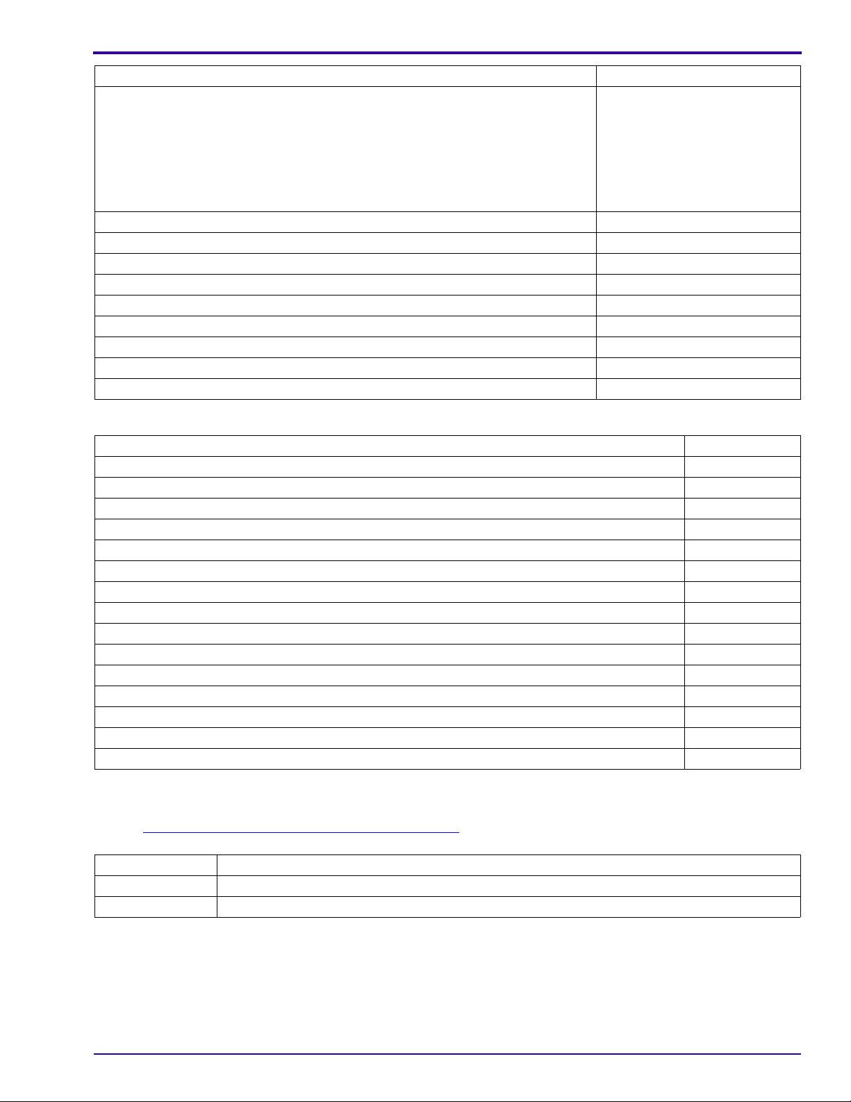
Configurations for the CAMERA DOCK
CUSTOM
DOCK
INSERT
DOCK ADAPTER
KIT D-22
CAMERA
DOCK
6000
Figure 2
CUSTOM
DOCK
INSERT
CAMERA
DOCK
SERIES 3
P252_0075BAFigure 1
Note
• You must use the Kodak DOCK ADAPTER KIT D-22 when connecting the Kodak EasyShare C643 ZOOM
DIGITAL CAMERA or the C603 ZOOM DIGITAL CAMERA to the Kodak EasyShare CAMERA DOCK 6000.
•The Kodak EasyShare C643 and C603 ZOOM DIGITAL CAMERAS are compatible with:
– Kodak EasyShare CAMERA DOCK SERIES 3
– other 26-PIN DOCKS
6 19JUN06 – SM1399-1
Page 7

Illustrated Parts List
Reference Table for New CAMERAS
Use the following catalog numbers to order a replace m en t CAM E RA if the CAME R A is under wa rr an ty an d cann o t
be repaired, or to order a MASTER CAMERA.
Region Language
Americas and Canada, with SENSORMATIC and
CHECKPOINT TAG
Americas and Canada, Non-OFM, with SENSORMATIC
and CHECKPOINT TAG
Brazil • Italian
Europe, Africa, and the Middle East • English
Europe, Africa, and the Middle East • Italian
Europe, Africa, and the Middle East
• English
• French
• Spanish
• English
• French
• Spanish
• Spanish
• Portuguese
• French
• German
• Spanish
• Portuguese
Nordic:
Catalog No. for
C643
857 7355 157 4763
168 4869 102 9766
198 7650 802 2550
859 4129 167 4399
393 6903 393 6978
393 6911 393 6986
Catalog No. for
C603
• Swedish
• Danish
• Finnish
Europe, Africa, and the Middle East
Emerging:
393 6929 393 6994
• English
• Russian
• Turkish
• Polish
Greater China and Taiwan • English
• Chinese
– simplified
– traditional
100 0587 187 4775
• Korean
People’s Republic of China • English
• Chinese
– simplified
– traditional
868 8343 127 3135
• Korean
Asia Pacific and Korea • English
• Chinese
– simplified
– traditional
120 7042 866 5648
• Korean
Japan Japanese 188 2729 120 9717
Kodak Service & Support - bulk, class A English
Kodak Service & Support - retail, class A English
SP 864 4676 SP 187 9659
SP 857 7355 SP 157 4763
SM1399-1 – 19JUN06 7
Page 8

SERVICE MANUAL
Region Language
Kodak Service & Support - bulk, class B English
Kodak Service & Support - retail, class B English
Reference Table for Adjustment Procedures
Component Procedure
LENS AY AND MCU BOARD • MCU BOARD/LENS AY - “Shutter Delay”
• CCD - “AWB/ ISO/DBP” on Page 40
Catalog No. for
C643
SP 864 4676 SP 192 7417
SP 866 5580 SP 116 4789
on Page 36
Catalog No. for
C603
8 19JUN06 – SM1399-1
Page 9
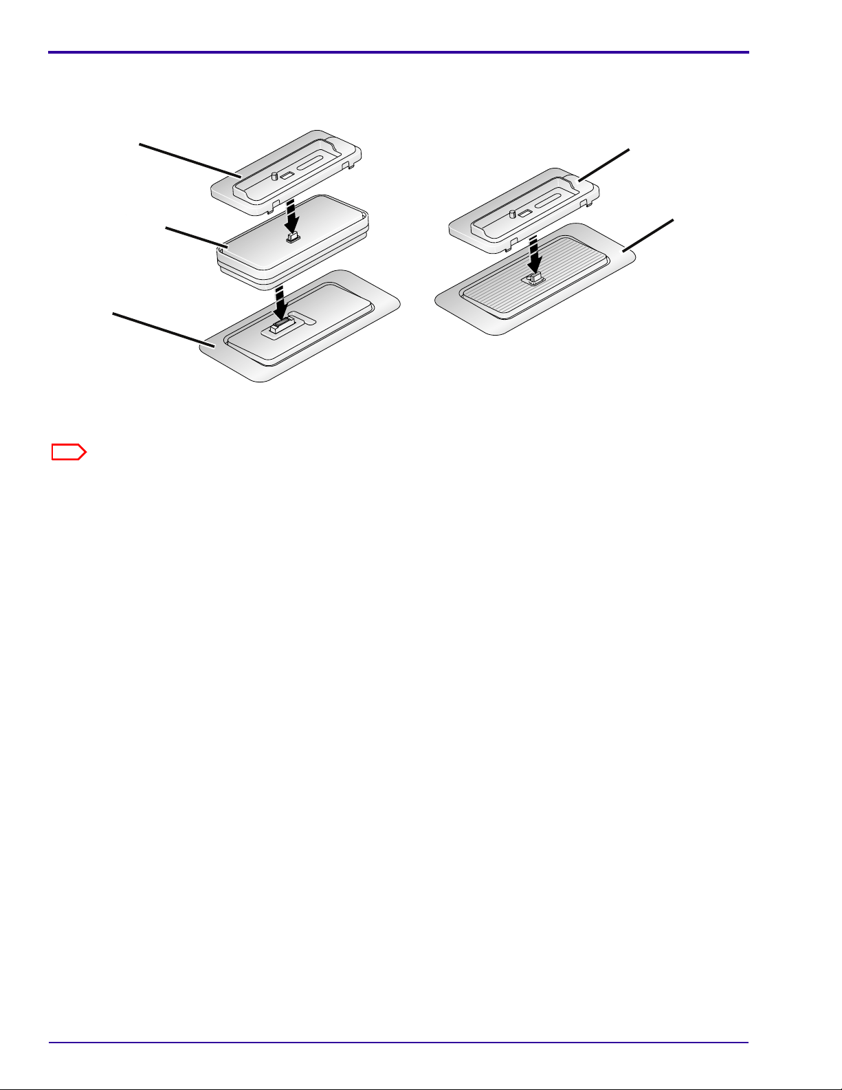
Visual Index
Illustrated Parts List
1
2
3
1
P273_1000DCA
P273_1000DC
Item Description
1 “
COVER AYs” on Page 10
2 “MONITOR LCD” on Page 12
3 “LENS AY AND MCU BOARD, POWER BOARD AND FRAME AY, SHUTTER BOARD” on Page 13
SM1399-1 – 19JUN06 9
Page 10
SERVICE MANUAL
Equipment Parts
Caution
Before removing the BACK COVER AY, you must:
• remove, if installed:
– MEMORY CARD
– BATTERY
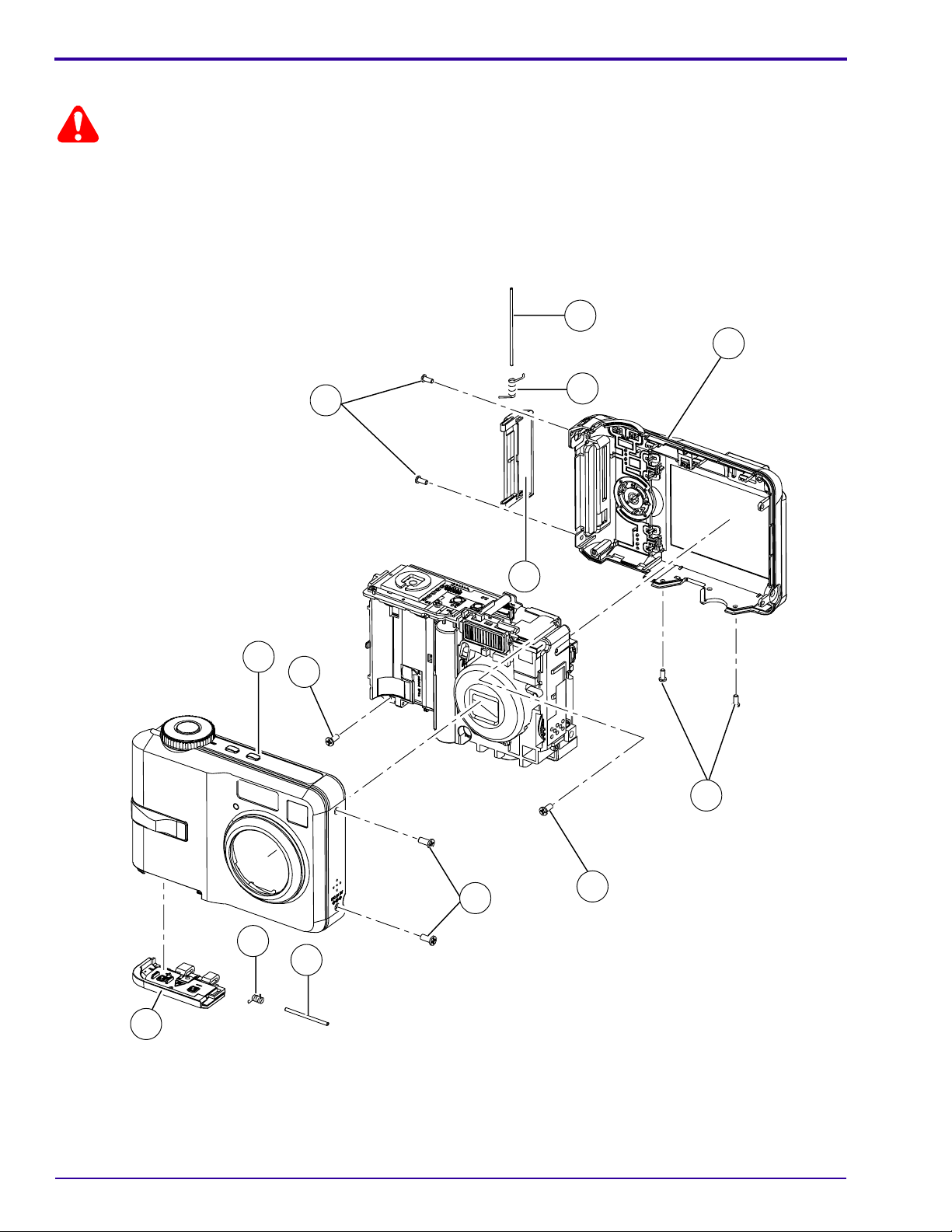
Figure 1 COVER AYs
1
1
5
5
2
2
6
6
4
4
3
3
1
1
1
1
1
1
1
8
8
7
7
9
9
1
P273_1001DCA
P273_1001DC
10 19JUN06 – SM1399-1
Page 11

Illustrated Parts List
Figure 1 COVER AYs
Item Part No. Description Quantity Notes
1 3F6374 SCREW - tapping, 1.7 x 4.0, nickel
2 3F9415 COVER - back, C643
3F9464 COVER - back, C603
3 3F9414 COVER - front, C643
3F9463 COVER - front, C603
4 3F9423 CARD DOOR AY - C643
3F9466 CARD DOOR AY - C603
5 3F9424 SHAFT - card door
6 3F9425 SPRING - card door
7 3F9421 SHAFT - battery door
8 3F9422 SPRING - battery door
9 3F9419 BATTERY DOOR - C643
3F9465 BATTERY DOOR - C603
------ 3F9618 PLATE - data, C643
------ 3F9619 PLATE - data, C603
------ 3F6387 STRAP - wrist
------ 3F9428 CUSTOM DOCK INSERT
1 8
1 1
1 1
1 1
1 1
1 1
1 1
1 1
1 1
1 1
1 1
1 1
1 1
1 1 Not visible in the graphic.
1 1 Not visible in the graphic.
1 1 Not visible in the graphic.
1 1 Not visible in the graphic.
SM1399-1 – 19JUN06 11
Page 12
SERVICE MANUAL
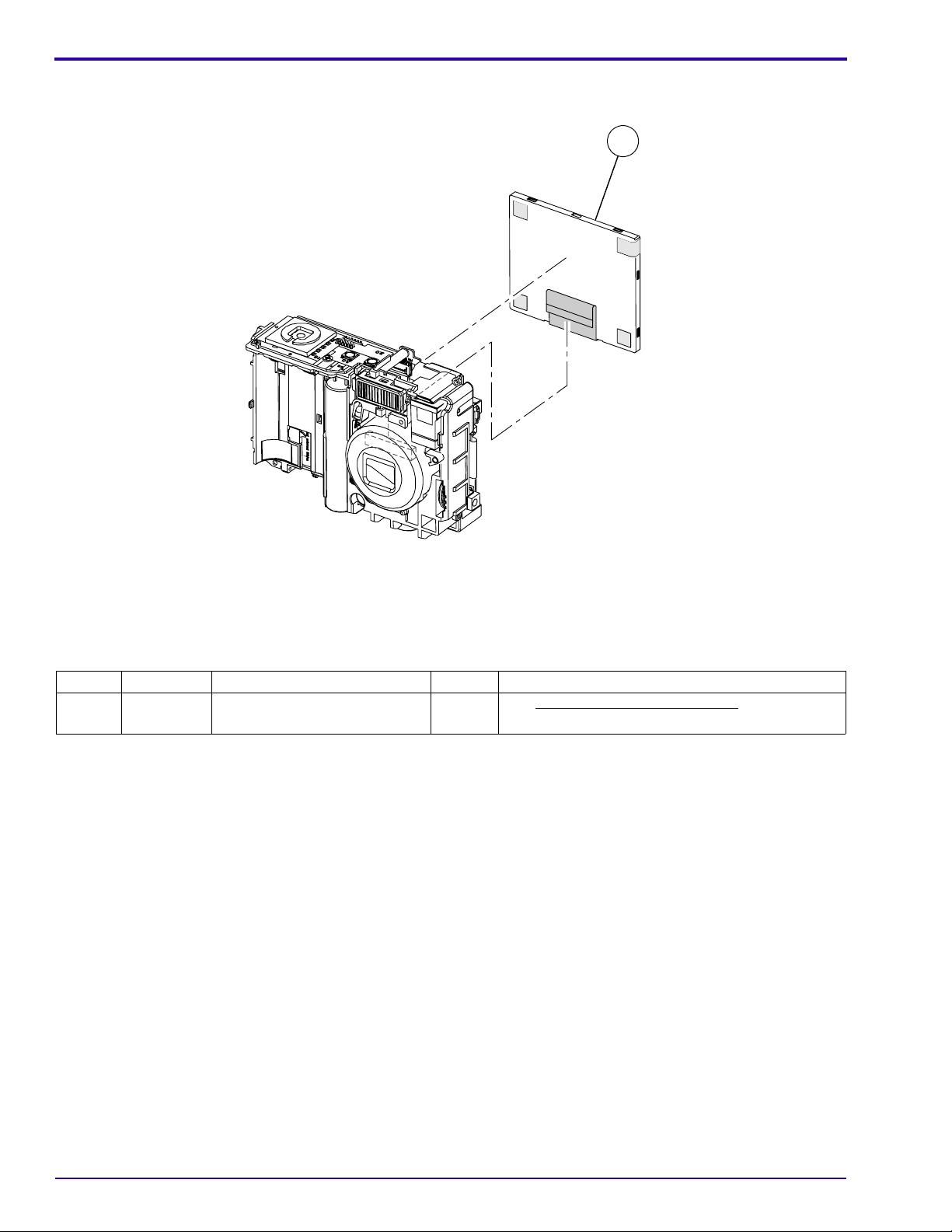
Figure 2 MONITOR LCD
1
1
Figure 2 MONITOR LCD
Item Part No. Description Quantity Notes
1 3F9413 MONITOR LCD
2 1See “MONITOR LCD” on Page 46 for special
replacement instructions.
P273_1002HCA
P273_1002HC
12 19JUN06 – SM1399-1
Page 13
Caution
Before removing the LENS AY AND MCU BOARD, you must:
• remove the SOLDER from the SOLDER JOINTS
• do a discharge of the CAPACITOR at the CONTACTS - see Step 1
“
POWER BOARD AND FRAME AY” on Page 44
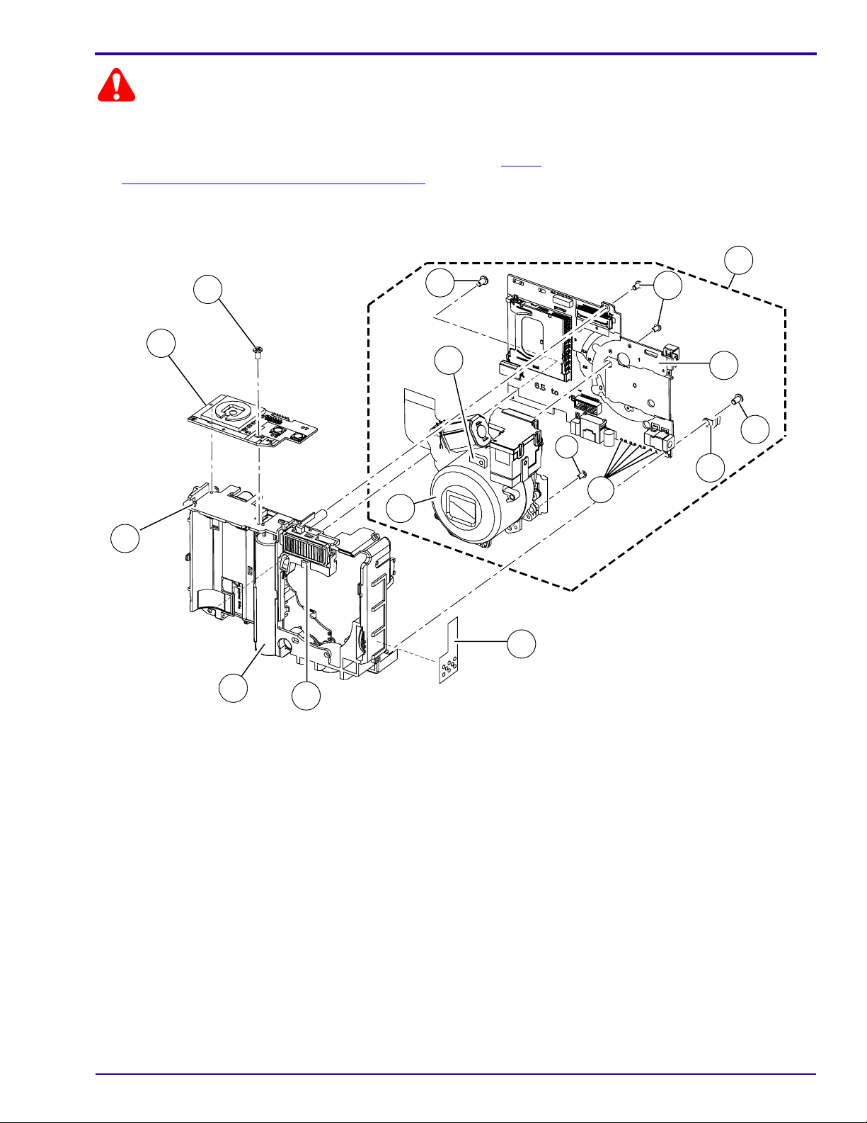
Figure 3 LENS AY AND MCU BOARD, POWER BOARD AND FRAME AY, SHUTTER BOARD
6
6
6
4
4
6
12
12
8
8
in To Remove: for the
6
6
6
6
1
1
Illustrated Parts List
2
2
7
7
6
6
5
5
11
11
9
9
3
3
10
10
P273_1003HCA
P273_1003HC
SM1399-1 – 19JUN06 13
Page 14

SERVICE MANUAL
Figure 3 LENS AY AND MCU BOARD, POWER BOARD AND FRAME AY, SHUTTER BOARD
Item Part No. Description Quantity Notes
1 ------ SOLDER JOINTS
2 3F9583 LENS AND MCU BOARD AY
3 5
3 1See “MCU BOARD” on Page 47 for details on
where the colored WIRES are soldered to the
MCU BOARD.
3 3F9417 POWER BOARD AND FRAME AY
3 1See “POWER BOARD AND FRAME AY” on
Page 44 for special replacement instructions.
4 3F9418 BOARD - shutter
5 3F9426 ESD PLATE - monitor LCD
6 3F6412 SCREW - tapping, 1.7 x 3.0, black
7 3F9416 BOARD - mcu
3 1
3 1
3 4
3 1See “MCU BOARD” on Page 47 for details on
where the colored WIRES are soldered to the
MCU BOARD.
8 3F9420 LENS AY
9 3F9443 ESD PLATE - speaker
10 ------ HOOK A
3 1
3 1
3 1 Release the LENS AY AND MCU BOARD from
the HOOK A.
11 ------ HOOK B
3 1 Release the SHUTTER BOARD from the
HOOK B.
12 ------ TAB
------ 3F6204 FUSE - 1.25 A, F3
------ 3F6205 FUSE - 2.5 A, F1, F2
3 1 Release the LENS AY from the TAB.
3 1See “POWER BOARD - 1 of 2” on Page 93.
3 1See “POWER BOARD - 2 of 2” on Page 94.
14 19JUN06 – SM1399-1
Page 15
Alphabetical Index
Section 2: Alphabetical Index
Alphabetical Index
Part No. Description Figure No.
3F9465 BATTERY DOOR - C603 1
3F9419 BATTERY DOOR - C643 1
3F9416 BOARD - mcu 3
3F9418 BOARD - shutter 3
3F9466 CARD DOOR AY - C603 1
3F9423 CARD DOOR AY - C643 1
3F9464 COVER - back, C603 1
3F9415 COVER - back, C643 1
3F9463 COVER - front, C603 1
3F9414 COVER - front, C643 1
3F9428 CUSTOM DOCK INSERT 1
3F9426 ESD PLATE - monitor LCD 3
3F9443 ESD PLATE - speaker 3
3F6204 FUSE - 1.25 A, F3 3
3F6205 FUSE - 2.5 A, F1, F2 3
------ HOOK A 3
------ HOOK B 3
3F9583 LENS AND MCU BOARD AY 3
3F9420 LENS AY 3
3F9413 MONITOR LCD 2
3F9619 PLATE - data, C603 1
3F9618 PLATE - data, C643 1
3F9417 POWER BOARD AND FRAME AY 3
3F6412 SCREW - tapping, 1.7 x 3.0, black 3
3F6374 SCREW - tapping, 1.7 x 4.0, nickel 1
3F9421 SHAFT - battery door 1
3F9424 SHAFT - card door 1
------ SOLDER JOINTS 3
3F9422 SPRING - battery door 1
3F9425 SPRING - card door 1
3F6387 STRAP - wrist 1
------ TAB 3
SM1399-1 – 19JUN06 15
Page 16

SERVICE MANUAL
Section 3: Diagnostics
Error Codes
E00
Description R ecommended Action
A communication error occurred between the
MCU and the 16-BIT MAIN CPU.
E12
Description Recommended Action
An error occurred when the LENS was retracted after
energizing the CAMERA.
1. Do “
2. Install a new MCU BOARD.
Upgrading the Firmware Using the MEMORY
CARD” on Page 74.
1. Check the FPC CABLE from the MOTOR to the
CONNECTOR J3 on the MCU BOARD.
2. Install a new MCU BOARD.
3. Install a new LENS AY.
E14
Description Recommended Action
An error occurred when the LENS was extended after
energizing the CAMERA.
E15
Description Recommended Action
An error occurred when the STEP MOTOR was reset
after energizing the CAMERA.
E20
Description Recommended Action
An error occurred when the CAMERA was writing to the
NANDFLASH memory.
1. Check the FPC CABLE from the MOTOR to the
CONNECTOR J3 on the MCU BOARD.
2. Install a new MCU BOARD.
3. Install a new LENS AY.
1. Check the FPC CABLE from the MOTOR to the
CONNECTOR J3 on the MCU BOARD.
2. Install a new MCU BOARD.
3. Install a new LENS AY.
1. Do “
2. Install a new MCU BOARD.
Upgrading the Firmware Using the MEMORY
CARD” on Page 74.
16 19JUN06 – SM1399-1
Page 17
Diagnostics
E22
Description Recommended Action
An error occurred when the LENS was retracted afte r
de-energizing the CAMERA.
1. Check the FPC CABLE from the MOTOR to the
CONNECTOR J3 on the MCU BOARD.
2. Install a new MCU BOARD.
3. Install a new LENS AY.
E25
Description Recommended Action
An error occurred when the STEP MOTOR was reset
after de-energizing the CAMERA.
1. Check the FPC CABLE from the MOTOR to the
CONNECTOR J3 on the MCU BOARD.
2. Install a new MCU BOARD.
3. Install a new LENS AY.
E41
Description Recommended Action
An error occurred when the LENS was retracting. 1. Check the FPC CABLE from the MOTOR to the
CONNECTOR J3 on the MCU BOARD.
2. Install a new MCU BOARD.
3. Install a new LENS AY.
E81
Description Recommended Action
An error occurred when the LENS was extending. 1. Check the FPC CABLE from the MOTOR to the
CONNECTOR J3 on the MCU BOARD.
2. Install a new MCU BOARD.
3. Install a new LENS AY.
Troubleshooting
LEDs
Description Recommended Action
The red VIEWFINDER LED is blinking. 1. Install a new BATTERY.
2. Check the BATTERY CONTACTS.
3. Install a new BATTERY DOOR AY.
SM1399-1 – 19JUN06 17
Page 18

SERVICE MANUAL
MONITOR LCD
Description Recommended Action
The MONITOR LCD does not energize. 1. Check the connection of the red and black wires
from the MONITOR LCD to the POWER BOARD
AND FRAME AY.
2. Check the condition of the SOLDER that connects
the POWER BOARD AND FRAME AY to:
• LENS AY
• VIEWFINDER
• MCU BOARD
• SOLDER that connects:
• MCU BOARD/LENS AY has no damage
• MONITOR LCD has no damage
3. Install:
• new MONITOR LCD
• new MCU BOARD/LENS AY
The MONITOR LCD energizes, but the screen is blank. 1. Check the FPC from the MONITOR LCD to
CONNECTOR J1 on the MCU BOARD.
2. Install:
• new MONITOR LCD
• new MCU BOARD/LENS AY
Malfunction of pixels occurs on the MONITOR LCD. Install a new MONITOR LCD.
The image on the MONITOR LCD is not in focus. Install a new MONITOR LCD.
Horizontal or vertical lines display on the MONITOR
LCD.
1. Check:
• FPC from the MONITOR LC D to CONNEC TOR
J1 on the MCU BOARD
• MCU BOARD/LENS AY has no damage
2. Install:
• new MONITOR LCD
• MCU BOARD/LENS AY
STROBE
Description Recommended Action
The STROBE does not energize. 1. Check that the correct mode of the STROBE is
selected.
2. Measure the voltage of the STROBE CAPACITOR
across both ends of the LAMP. The voltage should
be > 280 V.
3. Check:
• FUSE F4 on the POWER BOARD
• COIL and PLATE for the TRIGGER is soldered
correctly
The STROBE operates in the “Fill Flash” mode, but does
not operate in the “Auto Flash” mode.
18 19JUN06 – SM1399-1
Check the brightness of the environment.
Page 19

Description Recommended Action
Smoke emits from the CAMERA when the STROBE is
actuated.
The LAMP for the STROBE is dark. Do a replacement of the CAMERA.
Check:
• connection of the red and black wires between the
STROBE AY and the POWER FRAME AY
• STROBE COVER or STROBE REFLECTOR AY
has no debris
MEMORY CARD
Description Recommended Action
The CAMERA does not recognize the MEMORY CARD. 1. Use a new MEMORY CARD.
2. Check:
•“IMAGE STORAGE” option is set to “AUTO”
• SOCKET of the MEMORY CARD on the MCU
BOARD/LENS AY has no damage
3. Do “
Images are not stored on the MEMORY CARD. 1. Use a new MEMORY CARD.
2. Check:
3. Format the MEMORY CARD and capture an image
4. Do “
Upgrading the Firmware Using the Internal
Memory” on Page 75.
• position of the WRITE PROTECT SWITCH on
the SD CARD
•“IMAGE STORAGE” option is set to “AUTO”
• SOCKET of the MEMORY CARD on the MCU
BOARD/LENS AY has no damage
again.
Upgrading the Firmware Using the Internal
Memory” on Page 75.
Diagnostics
SM1399-1 – 19JUN06 19
Page 20

SERVICE MANUAL
Power
Description Recommended Action
The CAMERA does not energize. 1. Check:
• power source for the CAMERA
• FUSE F1 and F2 on the POWER BOARD. If
• BOARD-TO-BOARD CONNECTOR JP1 on the
2. Diagnose the MODULE that has the malfunction.
• Disconnect all MODULES from the MODE DIAL
• Connect the MODULES one at a time, until the
3. Install a new:
• MODE DIAL BOARD
• POWER BOARD
• MCU BOARD/LENS AY
The CAMERA with no BATTERY does not operate on
the CAMERA DOCK.
1. Check the DOCK CONNECTOR on the CAMERA.
2. Install a new MCU BOARD/LENS AY.
open, install a new FUSE.
MCU BOARD/LENS AY to J3 on the POWER
BOARD
BOARD.
FUSE opens.
Image Quality
Description Recommended Action
The images are black. 1. Check:
• BOARD-TO-BOARD CONNECTOR J1 on the
• FPC
• any sound from the SHUTTER
2. Install a new MCU BOARD/LENS AY.
• The image is not in focus.
• The color of the image is not correct.
• The images are too light.
• The images are too dark.
• The images have pixels that are continually
energized.
• The captured image is other than the image
displayed on the VIEWFINDER AY.
Install a new MCU BOARD/LENS AY.
MCU BOARD/LENS AY to J3 on the POWER
BOARD
20 19JUN06 – SM1399-1
Page 21

Diagnostics
Communication
Description Recommended Action
The CAMERA does not download images from the USB
PORT.
1. Connect the CAMERA to the computer to check for
communication.
2. Check for damage on:
• USB CONNECTOR to the PINS on the J3 on the
MCU BOARD
• BOARD-TO-BOARD CONNECTOR J1 on the
MCU BOARD/LENS AY to J3 on the POWER
BOARD
3. Install a new MCU BOARD/LENS AY.
General Functions
Description Recommended Action
One or more do not operate correctly:
•“menu” BUTTON
• FLASH BUTTON
•“share” BUTTON
•“delete” BUTTON
•“review” BUTTON
• 4-WAY BUTTON
•“OK” BUTTON
The SHUTTER BUTTON does not operate correctly. 1. Check the connection of the SHUTTER BOARD to
The SELF-TIMER LED does not operate correctly. Check the connection of the red and black wires from
1. Check for damage to:
• BUTTONS
• inside the BACK COVER AY
2. Install a new:
• BACK COVER AY
• MCU BOARD/LENS AY
the MCU BOARD/LENS AY.
2. Install a new:
• SHUTTER BOARD
• MCU BOARD/LENS AY
the SELF-TIMER LED to the MCU BOARD/LENS AY.
SM1399-1 – 19JUN06 21
Page 22

SERVICE MANUAL
Diagnostic Tests
Current Leakage Test
[1] Energize the DC POWER SUPPLY.
[2] Set the voltage to 3.0 V.
[3] Energize the DIGITAL MULTIMETER.
[4] Connect the DIGITAL MULTIMETER in series with the positive connection on the DC POWER SUPPLY.
[5] Set the DIGITAL MULTIMETER to read the current of 100 mA or less.
[6] Connect the POWER SUPPLY and the DIGITAL MULTIMETER to the BATTERY VOLTAGE ADJUSTMENT
TOOL.
[7] Check that the CAMERA is de-energized.
[8] Install the CAMERA on the BATTERY VOLTAGE ADJUSTMENT TOOL.
[9] Energize the CAMERA.
[10] Check that the current is within the limits:
During the first 10 seconds After 10 seconds
1 mA - 80 mA 0.5 mA - 20 mA
[11] Is the current within the limits?
Yes No
De-energize the CAMERA. 1. Install a new POWER BOARD AND FRAME AY.
2. Do Step 1
3. If the current is not within the limits again, do:
• install a new LENS AY AND MCU BOARD
• Step 1
4. De-energize the CAMERA.
- Step 10 again.
- Step 10 again
22 19JUN06 – SM1399-1
Page 23
Low Voltage Test
[1] Connect the DIGITAL MULTIMETER to the BATTERY VOLTAGE ADJUSTMENT TOOL:
To the BATTERY VOLTAGE
Wire Color From the DIGITAL MULTIMETER:
Red “+”“2.6 V”
Black Ground Ground
[2] Energize the DIGITAL MULTIMETER.
[3] Adjust the BATTERY VOLTAGE ADJUSTMENT TOOL to 2.5 V.
[4] Check that the CAMERA is de-energized.
[5] Install the CAMERA on the BATTERY VOLTAGE ADJUSTMENT TOOL.
[6] Rotate the MODE DIAL to “AUTO” to energize the CAMERA.
[7] Set the CAMERA to the “Fill Flash” mode.
[8] Press the SHUTTER BUTTON.
[9] Check:
• STROBE actuates
• image displays correctly
• low “Battery” icon displays
[10] Press:
•“review” BUTTON
•“T” BUTTON continually to a magnification to 8X
[11] Check the MONITOR for image quality.
[12] Do any of the following errors occur?
• red VIEWFINDER LED blinks
•“Battery” icon blinks
• error message “Batteries are too low for live view” displays
ADJUSTMENT TOOL
Diagnostics
Yes No
1. Install a new POWER BOARD AND FRAME AY.
2. Do Step 1
3. If any of these errors occur again, do:
• install a new LENS AY AND MCU BOARD
• Step 1
4. De-energize the CAMERA.
- Step 11 again .
- Step 11 again
De-energize the CAMERA.
SM1399-1 – 19JUN06 23
Page 24

SERVICE MANUAL
Checking the Power On “Self Test”
[1] Do Preparing the “C643_C603 Self_Test” MEMORY CARD on Page 70.
[2] Insert the “C643_C603 Self_Test” MEMORY CARD in the CAMERA:
[3] Do either:
• Install the CAMERA on the CAMERA DOCK.
• Insert a BATTERY that has a full charge into the CAMERA.
[4] Energize the CAMERA to execute the test.
[5] If the MONITOR LCD displays “Date and time have been reset”, select “CANCEL”.
[6] For each test displaying on the MONITOR LCD, do:
Test Check:
“F/W: n.nnnn” version of the firmware
“MCU: n.nnnn” version of the MCU
“RGB Level Checking...” quality of the 6 colors
“Gray Level Checking...” quality of the 6 gray areas
“LEDs On/Off testing”•green LED on the front of the CAMERA illuminates
• red and green LEDs on the back of the CAMERA illuminate
“LCD On/Off testing” MONITOR LCD blinks
“Strobe testing” STROBE energizes once
“SDRAM testing”•“SDRAM OK”
“IDRAM testing”
“SD card testing”
“NAND flash testing”
“Temperature checking...” message “OK”
“LCD Bad pixel testing” MONITOR LCD for:
•“IDRAM OK”
•“SD Card OK”
•“NAND Flash OK”
• dark pixels in the white screen
• white pixels in the dark screen
[7] When the test is completed, de-energize the CAMERA.
[8] Remove the MEMORY CARD.
24 19JUN06 – SM1399-1
Page 25
Checking for Uniform Flash
Diagnostics
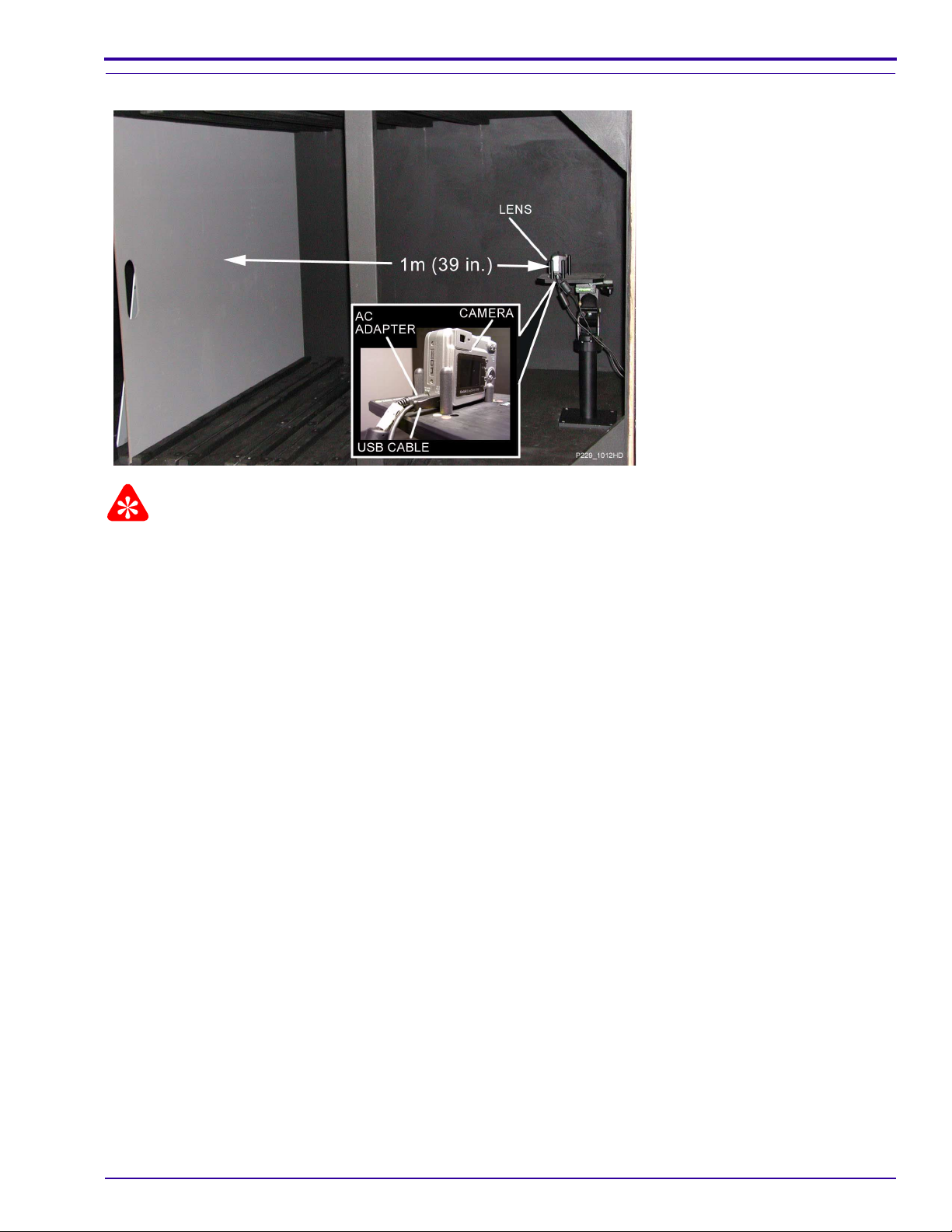
Important
• A dark room or the GEN 3 CUSTOM TEST FIXTURE can be used.
• The distance is measured from the surface of the TARGET to the front surf ace of the CAMERA.
SM1399-1 – 19JUN06 25
Page 26
SERVICE MANUAL
[1] If you are using:
GEN 3 CUSTOM TEST FIXTURE with Controlled Light Dark Room
a. Connect:
• USB CABLE between the CAMERA DOCK and the
computer
• 5 V AC ADAPTER to the CAMERA DOCK
b. Install the CAMERA ADAPTER on the CAMERA DOCK.
c. Adjust the GEN 3 CUSTOM TEST FIXTURE with:
• VERTICAL MEASURE TUBE “J” for T1
• HORIZONTAL MEASURE TUBE “H” and “K” for T4
•“X” axis to 1344
•“Y” axis to 1072
d. Place:
• 18% gray TARGET in the TARGET FRAME
• CAMERA DOCK on the CAMERA NEST
• CAMERA on the CAMERA DOCK
e. Press and hold:
•“review” BUTTON
•“T” TELE BUTTON
f. Rotate the MODE DIAL to “Auto”.
g. Release the BUTTONS.
h. Press the TRANSFER BUTTON on the CAMERA DOCK.
i. Check that the MONITOR LCD de-energizes.
j. Continue with Step 2
a. Place the TARGET 1 m (39.4 in.) from
the front surface of the CAMERA.
b. Continue with Step 2
.
.
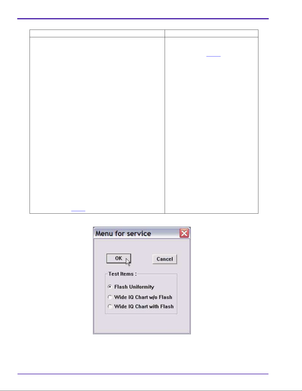
[2] Select “Flash Uniformity”.
[3] Click [OK].
26 19JUN06 – SM1399-1
Page 27
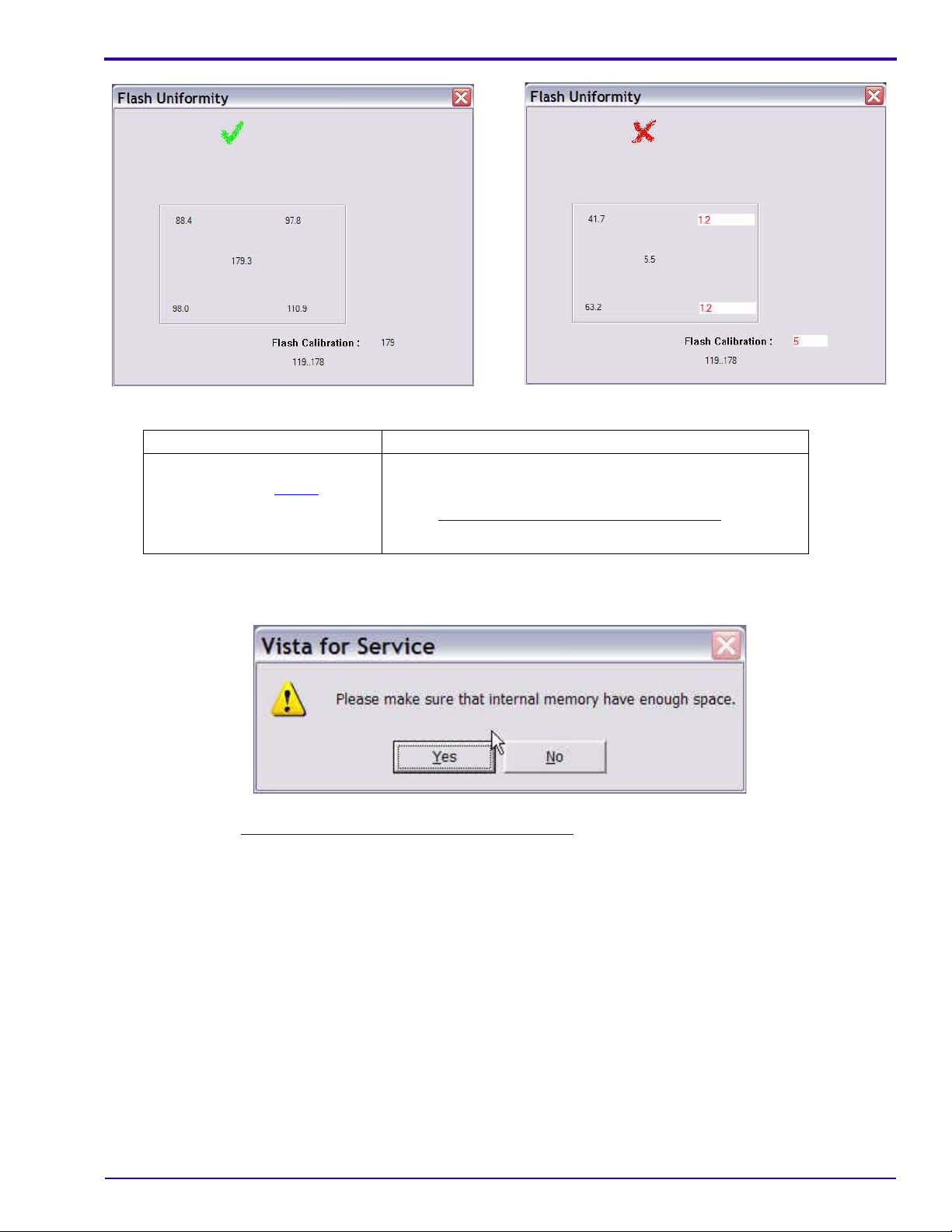
[4] Check the mark on the computer screen.
Green “✓” Red “X”
• The test was successful.
• Continue with Step 5
.
• A failure occurred.
• De-energize the CAMERA.
• Do “
• If the failure occurs again, check the hardware.
Diagnostics
Checking for Uniform Flash” on Page 25 again.
[5] Close “Flash Uniformity” window.
[6] Click [Yes].
[7] Continue with Checking “Wide IQ Chart w/o Flash”
on Page 28.
SM1399-1 – 19JUN06 27
Page 28
SERVICE MANUAL
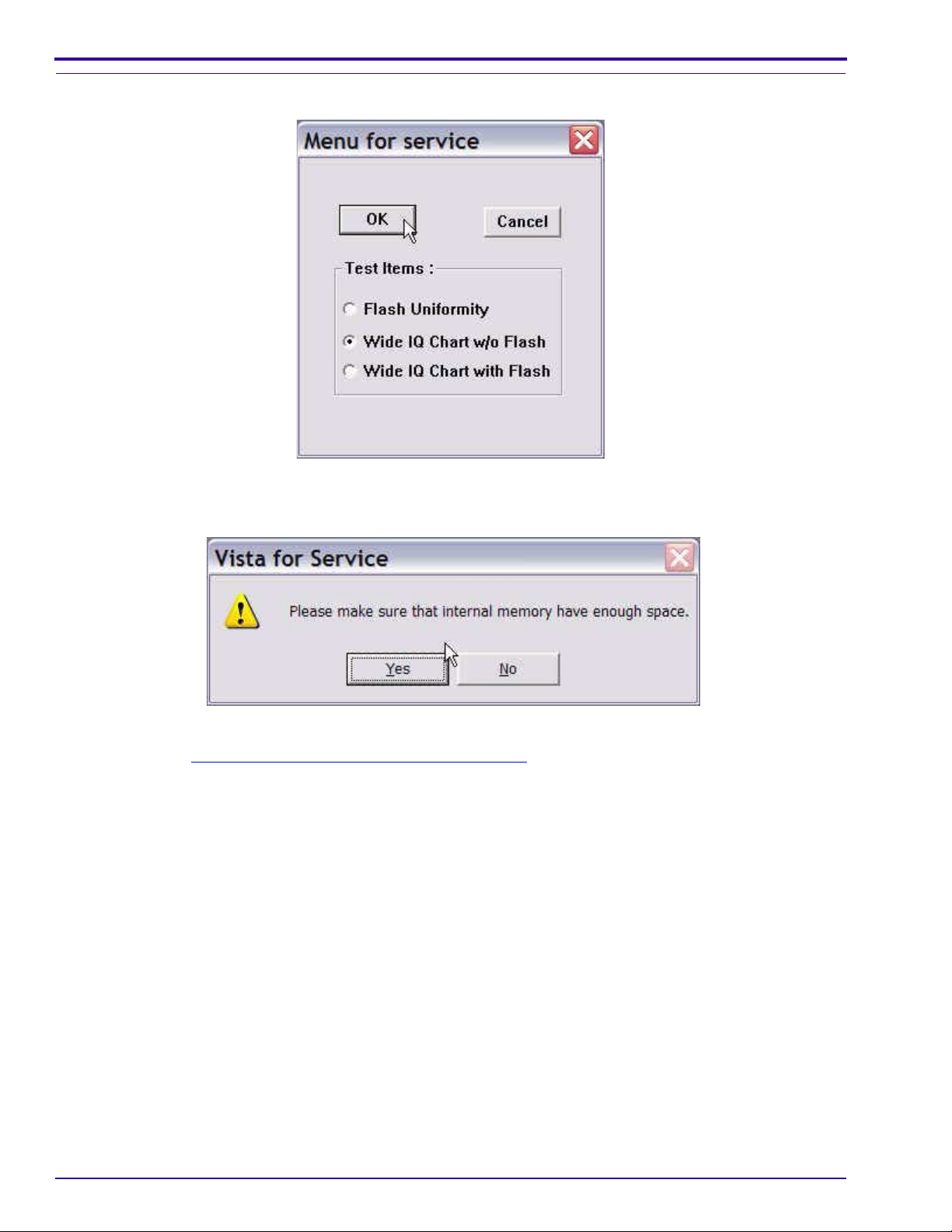
Checking “Wide IQ Chart w/o Flash”
[1] Select “Wide IQ Chart w/o Flash”.
[2] Click [OK].
[3] Click [Yes].
[4] Continue with Checking “Wide IQ Chart with Flash”
on Page 29.
28 19JUN06 – SM1399-1
Page 29
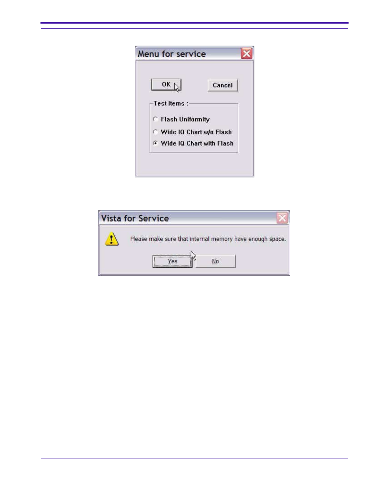
Checking “Wide IQ Chart with Flash”
[1] Select “Wide IQ Chart with Flash”.
[2] Click [OK].
Diagnostics
[3] Click [Yes].
[4] Close:
• “Menu for service” window
•“VISTA for SERVICE (Kodak)” window
[5] De-energize the CAMERA.
SM1399-1 – 19JUN06 29
Page 30

SERVICE MANUAL
Checkout Procedures
Checking the General Functions of the CAMERA
Important
Do these procedures before returning the CAMERA to the customer.
[1] Install the 5 V AC ADAPTER to:
• CAMERA DOCK
• source of power
[2] Connect the CAMERA DOCK to the computer with the USB CABLE.
[3] Remove the BATTERY from the CAMERA.
[4] Install the CAMERA on the CAMERA DOCK. See “
[5] Check that the STATUS LED on the CAMERA DOCK illuminates green.
[6] Remove the CAMERA from the CAMERA DOCK.
[7] Install:
• CRV3 BATTERY in the CAMERA
• CAMERA on the CAMERA DOCK
[8] Check:
• none of the LEDs for the BATTERY on the CAMERA DOCK illuminate green
• STATUS LED on the CAMERA DOCK illuminates green
[9] Remove:
• CAMERA from the CAMERA DOCK
• CRV3 BATTERY from CAMERA
[10] Install:
• Ni-MH BATTERY in the CAMERA
• CAMERA on the CAMERA DOCK
[11] Check:
• one or more of the LEDs for the BATTERY on the CAMERA DOCK illuminate green
• STATUS LED on the CAMERA DOCK illuminates green
[12] Remove the CAMERA from the CAMERA DOCK.
[13] Energize the CAMERA.
[14] Check that the CAMERA energizes.
[15] De-energize the CAMERA.
[16] Remove the BATTERY from the CAMERA.
[17] Insert the MEMORY CARD into the CAMERA.
[18] Install the CAMERA on the CAMERA DOCK. See “
[19] Rotate the MODE DIAL to the “AUTO” position.
[20] Check the energize sequence:
• green LED illuminates on the CAMERA DOCK
• green LED to the right of the VIEWFINDER
– blinks 2 times
– remains illuminated
• error code does not display
[21] De-energize the CAMERA.
[22] Remove the CAMERA from the CAMERA DOCK.
Configurations for the CAMERA DOCK” on Page 6.
Configurations for the CAMERA DOCK” on Page 6.
30 19JUN06 – SM1399-1
Page 31

[23] Install a new BATTERY that has a full charge into the CAMERA.
[24] Rotate the MODE DIAL to the “AUTO” position.
[25] Check the energize sequence:
• green LED to the right of the VIEWFINDER:
– blinks 5 times
– remains illuminated
• error code does not display
[26] Check the following BUTTONS and SWITCHES:
BUTTON/SWITCH Do:
•“menu”
• 4-WAY
•“OK”
1. Press the “menu” BUTTON.
2. Check that the MONITOR LCD illuminates.
3. Press:
• 4-WAY BUTTON up or down to move through the menu
•“OK” BUTTON to select an option
•“OK” BUTTON again to return to the screen before
•“menu” BUTTON to quit
4. Press:
•“menu” BUTTON
• SHUTTER BUTTON
5. Check:
• CAMERA quits the menu
• image is captured
• image displays on the MONITOR LCD
•“review”
•“share”
1. Press the “review” BUTTON.
2. Check that the MONITOR LCD illuminates.
3. Press:
• 4-WAY BUTTON left and right to display images
•“share” BUTTON
4. Check that options display.
5. Press:
•“share” BUTTON
•“review” BUTTON again to quit
6. Press:
•“review” BUTTON
• SHUTTER BUTTON
7. Check:
• CAMERA quits the “Review” mode
• image is captured
• image displays on the MONITOR LCD
Diagnostics
SM1399-1 – 19JUN06 31
Page 32

SERVICE MANUAL
BUTTON/SWITCH Do:
FLASH 1. Press the FLASH BUTTON.
SHUTTER 1. Press the SHUTTER BUTTON to capture an image.
2. Check that the MONITOR LCD illuminates.
3. Press the FLASH BUTTON again 3 times to check that the “Flash” icon
changes to:
•“Auto Flash”
•“Fill Flash”
•“Red Eye”
•“Flash Off”
4. Press the SHUTTER BUTTON.
5. Check:
• image is captured without the FLASH
• image displays on the MONITOR LCD
2. Check:
• green LED blinks once before the CAMERA captures the image
• image appears on the MONITOR LCD
• green LED blinks when the CAMERA stores the image
32 19JUN06 – SM1399-1
Page 33

BUTTON/SWITCH Do:
“delete” 1. Press:
•“review” BUTTON
•“delete” BUTTON
2. Check that options display.
3. Select the “EXIT” option.
4. Press:
•“OK” BUTTON to quit the “delete” screen
•“review” BUTTON to return to the “Auto” mode
5. Press:
•“review” BUTTON
•“delete” BUTTON
• SHUTTER BUTTON to capture an image
6. Check:
• CAMERA quits the “delete” screen
• image is captured
• image displays on the MONITOR LCD
7. Immediately press the “delete” BUTTON.
8. Use the 4-WAY BUTTON to select “YES”.
9. Press:
•“OK” BUTTON
•“review” BUTTON
10. Use the 4-WAY BUTTON to check that the image is deleted.
11. Press the “delete” BUTTON.
12. Use the 4-WAY BUTTON to select “PICTURE”.
13. Press:
•“OK” BUTTON to delete the image
•“OK” BUTTON again to select “EXIT”
14. Use the 4-WAY BUTTON to check that the image is deleted.
15. Press the “review” BUTTON to quit.
Diagnostics
[27] Press:
• 4-WAY BUTTON left and right to check that the exposure value changes
• SHUTTER BUTTON to capture an image
[28] Check that the MONITOR LCD displays:
• image
• icons:
–“Flash” mode
– quality of the image
– type of memory
–“Zoom” mode
– exposure value
• number of additional images that can be captured
SM1399-1 – 19JUN06 33
Page 34

SERVICE MANUAL
[29] Check the positions of the MODE DIAL.
After moving the
MODE DIAL to: Do:
“Video” 1. Check:
•“Video:” displays on the MONITOR LCD
• FRAMING MARKS are disabled
2. Press and release the SHUTTER BUTTON.
3. During the video recording, check:
• green LED flashes
•“REC” on the MONITOR LCD flashes
• recording time displays on the MONITOR LCD
4. Press and release the SHUTTER BUTTON.
5. Check that the MONITOR LCD displays “Press OK to Play or Pause”.
6. Press the “OK” BUTTON.
7. Check that the video begins to play back.
8. Press the “OK” BUTTON.
9. Check that the video stops.
10. Press the “delete” BUTTON.
11. Check that the MONITOR LCD displays “VIDEO” in the list of options.
12. Press:
•“delete” BUTTON to quit
•“review” BUTTON
13. Check that the MONITOR LCD illuminates in “Liveview” mode.
“Favorites” 1. Check that “Entering Favorites...” displays on the MONITOR LCD.
2. Press the “menu” BUTTON.
3. Check that the MONITOR LCD displays a list of options.
4. Press:
•“menu” BUTTON to quit
•“review” BUTTON
34 19JUN06 – SM1399-1
Page 35

Diagnostics
Checking the Communication
[1] Connect the CAMERA DOCK to the computer with the USB CABLE for the CAMERA DOCK.
[2] Download the images and the video file with the USER SOFTWARE.
[3] Check the quality of the images.
[4] Do “
[5] Remove the CAMERA from the CAMERA DOCK.
[6] Connect the CAMERA to the computer with the USB CABLE for the CAMERA.
[7] Download the 2 images with the USER SOFTWARE. If successful, the USB CONNECTOR on the MCU
Checking the Connection to the SERVICE SOFTWARE” on Page 63. If successful, the USB inte r face on
the DOCK CONNECTOR is operating correctly.
BOARD is operating correctly.
Checking the Accessories
[1] Disconnect the USB CABLE from the CAMERA.
[2] Connect the VIDEO MONITOR to the CAMERA with the VIDEO CABLE.
[3] If you are not using the internal memory, insert a MEMORY CARD with image files into the CAMERA.
[4] Energize the CAMERA.
[5] Press the “review” BUTTON.
[6] Check that the MONITOR LCD de-energizes and the image displays on the VIDEO MONITOR.
[7] De-energize the CAMERA.
[8] Remove the MEMORY CARD.
[9] Energize the CAMERA.
[10] Check that the green LED next to the VIEWFINDER blinks.
Checking the External Components of the CAMERA
[1] Check the COVERS of the CAMERA for scratches.
[2] If necessary, install new COVERS.
[3] Clean:
• COVERS
• SCREEN on the MONITOR LCD
• VIEWFINDER WINDOW
• FLASH COVER
[4] Check and clean the LENS.
SM1399-1 – 19JUN06 35
Page 36

SERVICE MANUAL
Section 4: Adjustments
MCU BOARD/LENS AY - “Shutter Delay”
Adjustment Specification
Important
Do not use the CAMERA DOCK in this procedure.
Purpose: To set the parameters for the speed of the SHUTTER.
Do When: • After installing a new MCU BOARD/LENS AY.
• Exposure of the images displayed on the MONITOR LCD is too high or too low.
Specification: No failure messages display.
Special Tools: • Computer with a MEMORY CARD READER/WRITER
• BATTERY
• LIGHT BOX
• SD/MMC MEMORY CARDS
Prerequisites:
None
To Check:
You cannot check this adjustment.
To Adjust:
Important
• The C643 CAMERA and MEMORY CARDS are used for the examples in this procedure.
• The procedure can be used for:
– C643 CAMERA
– C603 CAMERA
• If you are doing a calibration of the C6 03 CAMERA, use th e correct MASTER CAMERA an d MEMORY CARDS
made for that CAMERA.
[1] Do Preparing the “C643_C603 Shutter_Delay” MEMORY CARD
[2] Insert:
• new BATTERY with a full charge into the C643 CAMERA
•“C643_C603 Shutter_Delay” MEMORY CARD into the CAMERA
[3] Set the LIGHT BOX to LV15.
[4] Place the center of the LENS against the screen of the LIGHT BOX.
[5] Rotate the MODE DIAL to “AUTO” to execute the test.
[6] If the MONITOR LCD displays “Date and time have been reset”, select “CANCEL”.
[7] When the test is completed, check that the MONITOR LCD displays “Shutter Calibrate OK”.
[8] De-energize the CAMERA.
[9] Remove the MEMORY CARD from the CAMERA.
on Page 71.
36 19JUN06 – SM1399-1
Page 37

Postrequisites:
None
Adjustments
SM1399-1 – 19JUN06 37
Page 38

SERVICE MANUAL
MASTER CAMERA - “Calibration of the MASTER CAMERA”
Adjustment Specification
Important
Do not use the CAMERA DOCK in this procedure.
Purpose: To set the values for Automatic White Balance, ISO, and ID of the MASTER CAMERA.
Do When: Before calibrations of this type of CAMERA.
Specification: No failure messages display.
Special Tools: • Computer with a MEMORY CARD READER/WRITER
• BATTERY
• LIGHT BOX
• SD/MMC MEMORY CARDS
Prerequisites:
[1] Do MCU BOARD/LENS AY - “Shutter Delay” on Page 36.
To Check:
You cannot check this adjustment.
To Adjust:
Important
• The C643 CAMERA and MEMORY CARDS are used for the examples in this procedure.
• The procedure can be used for:
– C643 CAMERA
– C603 CAMERA
• If you are doing a calibration of the C6 03 CAMERA, use th e correct MASTER CAMERA an d MEMORY CARDS
made for that CAMERA in the procedure in Step 1
[1] Do Preparing the “C643_C603 Master Camera” MEMORY CARD
[2] Insert:
• new BATTERY with a full charge into a MASTER CAMERA for the C643 CAMERA
•“C643_C603 Master Camera” MEMORY CARD into the CAMERA
.
on Page 68.
38 19JUN06 – SM1399-1
Page 39

Adjustments
[3] Place the CAMERA in front of the LIGHT BOX.
• The LENS must be within 3 mm (0.1 in.) of the screen, but not touch ing the screen of the LIGHT BOX.
• The center of the LENS must be placed in the center of the light.
[4] Set the LIGHT BOX to LV10.
[5] Rotate the MODE DIAL to “AUTO” to execute the test.
[6] If the MONITOR LCD displays “Date and time have been reset”, select “CANCEL”.
[7] When the test is completed, check that the MONITOR LCD displays “Big LB OK”.
[8] De-energize the CAMERA.
Important
You must use the same LIGHT BOX when using this MEMORY CARD for calibration of other C643 CAMERAS.
[9] Remove the MEMORY CARD.
[10] Check that the following 4 additional files were written on the MEMORY CARD:
•“BIG_LAMP.fig”
•“BoxID_ref.fig”
•“CameraID_ref.fig”
•“K_RESULT.txt”
[11] Do Step 2
[12] When the test is completed, check that the MONITOR LCD displays “Small LB OK”.
[13] De-energize the CAMERA.
[14] Remove the MEMORY CARD.
[15] Check that the following 2 additional files were written on the MEMORY CARD:
•“CamerID_ref.fig”
•“Small_LAMP.fig”
to Step 6 again.
Note
These 6 files are necessary before you do Preparing the “C643_C603 AWB_ISO_DBP” MEMORY CARD on
Page 65.
[16] If the MONITOR LCD displays a failure message, do the correction:
Failure Cause Correction
“W/O Shutter K” The calibration of the SHUTTER
was not correct.
“Memory Fail” An occasional failure occurred
during a test of the memory.
“ISO Cal Fail” A failure occurred during the
calibration.
Do:
1. “
Preparing the “C643_C603 Shutter_Delay”
MEMORY CARD” on Page 71
2. Preparing the “C643_C603 Master Camera”
MEMORY CARD on Page 68 again
1. Do Preparing the “C643_C603 Master Camera”
MEMORY CARD on Page 68 again.
2. If the message occurs again, check the har dw ar e.
1. Check:
• LIGHT BOX
• LV value
2. Do Preparing the “C643_C603 Master Camera”
MEMORY CARD on Page 68 again.
Postrequisites:
None
SM1399-1 – 19JUN06 39
Page 40

SERVICE MANUAL
CCD - “AWB/ ISO/DBP”
Adjustment Specification
Important
Do not use the CAMERA DOCK in this procedure.
Purpose: To set the values for Automatic White Balance, ISO, and ID of the CAMERA.
Do When: After installing a new MCU BOARD/LENS AY.
Specification: The failure message does not display.
Special Tools: • Computer with a MEMORY CARD READER/WRITER
• BATTERY
• LIGHT BOX
• SD/MMC MEMORY CARDS
Prerequisites:
[1] Do MASTER CAMERA - “Calibration of the MASTER CAMERA” on Page 38.
To Check:
You cannot check this adjustment.
To Adjust:
Important
• The C643 CAMERA and MEMORY CARDS are used for the examples in this procedure.
• The procedure can be used for:
– C643 CAMERA
– C603 CAMERA
• You will need the files made from the procedure MASTER CAMERA - “Calibration of the MASTER CAMERA”
Page 38.
[1] Do “
[2] Make a copy of the following files from the “C643_C603 Master Camera” MEMORY CARD:
[3] Place these 6 files in the folder “Batch” on the “C643_C603 AWB_ISO_DBP” MEMORY CARD.
[4] Insert:
[5] Set the LIGHT BOX to:
Preparing the “C643_C603 AWB_ISO_DBP” MEMORY CARD” on Page 65.
•“BIG_LAMP.fig”
•“BoxID_ref.fig”
•“CameraID_ref.fig”
•“K_RESULT.txt”
•“CamerID_ref.fig”
•“Small_LAMP.fig”
• new BATTERY with a full charge into a C643 CAMERA
•“C643_C603 AWB_ISO_DBP” MEMORY CARD into the CAMERA
• LV10
• color temperature 5800 K
on
40 19JUN06 – SM1399-1
Page 41

[6] Place the center of the LENS against the screen of the LIGHT BOX.
[7] Rotate the MODE DIAL to “AUTO” to execute the test.
[8] If the MONITOR LCD displays “Date and time have been reset”, select “CANCEL”.
[9] When the test is completed, check that the MONITOR LCD displays “ISO Cal OK”.
Note
The result file “K_RESULT.TXT” is written to the MEMORY CARD.
[10] De-energize the CAMERA.
[11] Remove the MEMORY CARD from the CAMERA.
[12] If the MONITOR LCD displays the failure message “ISO Cal Fail”:
• open the file “K_RESULT.TXT” to obt ain the type of failure
• do the necessary correction
Failure Cause Correction
“W/O Shutter K” The calibration of the SHUTTER was
not correct.
“Memory Fail” An occasional failure occurred during
a test of the memory.
“ISO Cal Fail” A failure occurred during the
calibration.
Do:
1. MCU BOARD/LENS AY - “Shutter Delay”
Page 36
2. CCD - “AWB/ ISO/DBP” on Page 40 again
1. Do CCD - “AWB/ ISO/DBP”
again.
2. If the message occurs again, check the
hardware.
1. Check:
• LIGHT BOX
• LV value
2. Do CCD - “AWB/ ISO/DBP”
again.
Adjustments
on
on Page 40
on Page 40
Postrequisites:
None
SM1399-1 – 19JUN06 41
Page 42

SERVICE MANUAL
Auto Focus - “EFA”
Adjustment Specification
Important
Do not use the CAMERA DOCK in this procedure.
Purpose: To set the values for Automatic Focus.
Do When: After installing a new:
• MCU BOARD/LENS AY
• LENS AY
Specification: The message “OK” displays on the MONITOR LCD.
Special Tools: • Computer with a MEMORY CARD READER/WRITER
• BATTERY
• INFINITY COLLIMATOR VC-1100
• SD/MMC MEMORY CARDS
Prerequisites:
[1] Do MASTER CAMERA - “Calibration of the MASTER CAMERA” on Page 38.
To Check:
You cannot check this adjustment.
To Adjust:
Important
• The procedure can be used for:
– C643 CAMERA
– C603 CAMERA
• If you are doing a calibration of the C6 03 CAMERA, use th e correct MASTER CAMERA an d MEMORY CARDS
made for that CAMERA.
[1] Do “
[2] Make a copy of the following files from the “C643_C603 Master Camera” MEMORY CARD:
[3] Place these 6 files in the folder “Batch” on the “C643_C603 EFA” MEMORY CARD.
[4] Insert:
[5] Place the CAMERA on the CAMERA HOLDER in the INFINITY COLLIMATOR.
[6] Rotate the MODE DIAL to “AUTO”.
Preparing the “C643_C603 EFA” MEMORY CARD” on Page 67.
•“BIG_LAMP.fig”
•“BoxID_ref.fig”
•“CameraID_ref.fig”
•“K_RESULT.txt”
•“CamerID_ref.fig”
•“Small_LAMP.fig”
• AC ADAPTER in the CAMERA
•“C643_C603 EFA” MEMORY CARD into the CAMERA
42 19JUN06 – SM1399-1
Page 43

[7] If the MONITOR LCD displays “Date and time have been reset”, select “CANCEL”.
[8] Press the SHUTTER BUTTON to execute the test.
[9] Check that the test runs 6 times.
[10] When the test is completed, check that the MONITOR LCD displays “OK”.
[11] De-energize the CAMERA.
[12] Remove the MEMORY CARD from the CAMERA.
[13] Did the MONITOR LCD display the failure message “NG”?
Yes No
a. Install a new LENS AY AND MCU BOARD.
b. Do Step 4
c. If the MONITOR LCD displayed the failure
message “NG” again, install a new POWER
BOARD AND FRAME AY.
d. Do Step 4
[14] Capture some images at a variation of z oom positions of the LENS.
[15] Review the images on the MONITOR LCD.
[16] Check that the images are not too da rk or too light.
[17] Press the “T” BUTTON to increase the magnification of the images to the maximum.
[18] Check that the images on the MONITOR LCD are in focus.
- Step 12 again .
- Step 12 again .
Continue with Step 14
.
Adjustments
Postrequisites:
None
SM1399-1 – 19JUN06 43
Page 44

SERVICE MANUAL
Section 5: Replacements
Important
You must see the “Equipment Parts” on Page 10 for all parts information.
POWER BOARD AND FRAME AY
Prerequisites:
None
To Remove:
Caution
To prevent injury, you must do a discharge of the CAPACITOR.
[1] Before removing the POWER BOARD, do a discharge of the CAPACITOR across the CONTACTS on the
MCU BOARD.
[2] See “
44 19JUN06 – SM1399-1
LENS A Y AND MCU BOARD, POWER BOARD AND FRAME AY, SHUTTER BOARD” on Page 13 for the
parts diagram.
Page 45

To Install:
Important
You must do this procedure when you do a replacement of the POWER BOARD AND FRAME AY.
[1] Compare the serial number of the CAMERA with the “Beginning Serial Number”:
CAMERA Beginning Serial Number
C643 KCGFN61713506
C603 KCGFP61901199
[2] Is the serial number the same or higher than the “Beginning Serial Number”?
No Yes
Continue with Step 3
[3] Remove the RESISTOR R13 from the new replacement POWER BOARD AND FRAME AY.
Note
See “POWER BOARD - 2 of 2” on Page 94 to locate the RESISTOR R13.
[4] Discard the RESISTOR R13.
[5] Remove the RESISTOR R13 from the old POWER BOARD AND FRAME AY.
[6] Install:
• RESISTOR R13 on the new POWER BOARD AND FRAME AY
• new POWER BOARD AND FRAME AY
[7] Assemble the CAMERA.
. 1. Install a new POWER BOARD AND FRAME AY.
2. Advance to Step 7
.
Replacements
Postrequisites:
None
SM1399-1 – 19JUN06 45
Page 46

SERVICE MANUAL
MONITOR LCD
Prerequisites:
None
To Remove:
Caution
To prevent injury, you must do a discharge of the CAPACITOR - see Step 1 in To Remove: for the
“
POWER BOARD AND FRAME AY” on Page 44.
[1] See “
To Install:
You must do this procedure when you do a replacement of the MONITOR LCD.
[1] Compare the serial number of the CAMERA with the “Beg inning Serial Number”:
MONITOR LCD” on Page 12 for the parts diagram.
Important
CAMERA Beginning Serial Number
C643 KCGFN61713506
C603 KCGFP61901199
[2] Is the serial number the same or higher than the “Beginning Serial Number”?
No Yes
Continue with Step 3
[3] Remove:
• MONITOR LCD
• POWER BOARD AND FRAME AY
. 1. Install a new MONITOR LCD.
2. Advance to Step 5
.
Important
See the replacement procedure for the “POWER BOARD AND FRAME AY” on Page 44.
[4] Install a new:
• POWER BOARD AND FRAME AY
• MONITOR LCD
[5] Assemble the CAMERA.
[6] Do Preparing the “C643_C603 Monitor LCD” MEMORY CARD
[7] Insert the “C643_C603 Monitor LCD” MEMORY CARD in the CAMERA.
[8] Energize the CAMERA.
[9] Check that the MONITOR LCD displays the message “Script Loading... Run...”.
[10] Capture an image.
[11] Check the quality of the image displayed on the MONITOR LCD.
on Page 69.
Postrequisites:
None
46 19JUN06 – SM1399-1
Page 47

MCU BOARD
Prerequisites:
None
To Remove:
Caution
To prevent injury, you must do a discharge of the CAPACITOR - see Step 1 in To Remove: for the
“
POWER BOARD AND FRAME AY” on Page 44.
[1] See LENS AY AND MCU BOARD, POWER BOARD AND FRAME AY, SHUTTER BOARD
parts diagram.
To Install:
MCU BOARD
on Page 13 for the
Replacements
GW R B Y +
Important
You must install the large red and black wires on the right.
[1] Solder each WIRE at the correct CONTACT on the MCU BOARD:
CONTACT Size of WIRE Color of WIRE
G small green
W small white
Rsmallred
-
Bsmallblue
Y small yellow
+
-
small black
large red
large black
Postrequisites:
WIRES
P273_1006BCA
P273_1006BC
None
SM1399-1 – 19JUN06 47
Page 48

SERVICE MANUAL
Section 6: Additional Service Procedures
Downloading the Files from the Partner Site
[1] From the Kodak Partner site, download the software and firmware files from
Kodak EasyShare C643_C603_ ZOOM DIGITAL CAMERA_Software_and_Firmware.
[2] Right-click the “C643_C603_Software_Firmware.zip” file.
[3] Select WinZip>Extract to here.
[4] Open the folder
“C643_C603_Software_Firmware”.
[5] Open the folder “Service_Software”.
[6] Open the folder “Vista for Service V4.1.0.7”.
48 19JUN06 – SM1399-1
Page 49

Additional Service Procedures
[7] Check for th e 10 files.
[8] Click [Back] 2 times.
[9] Open the folder
“Firmware_and_Scripts_C643_C603”.
[10] Check for the 2 folders.
[11] Open the folder “Batch Files”.
SM1399-1 – 19JUN06 49
Page 50

SERVICE MANUAL
[12] Check f or 6 folders.
[13] Click [Back].
[14] Open the folder “Firmware”.
[15] Check for the firmware file.
50 19JUN06 – SM1399-1
Page 51

Additional Service Procedures
Installing the Altek Vista SERVICE SOFTWARE on the Computer
Important
Microsoft Windows XP OPERATING SYSTEM is necessary for the correct operation of the SERVICE SOFTWARE.
[1] Open the folder “Vista for Ser vice”.
[2] Open the folder “Setup”.
[3] Double-click “Setup.exe”.
SM1399-1 – 19JUN06 51
Page 52

SERVICE MANUAL
[4] Wait until:
• this window is complete
• the next window displays
[5] Click [Next>].
52 19JUN06 – SM1399-1
Page 53

Additional Service Procedures
[6] After selecting a folder, click [Ne xt>].
[7] Click [Yes].
SM1399-1 – 19JUN06 53
Page 54

SERVICE MANUAL
[8] Check that an icon for the “Vista for Service” appears on the computer screen.
[9] Connect the CAMERA to the computer with the USB CABLE.
[10] Energize the CAMERA.
[11] Check that the Kodak EasyShare SOFTWARE detects the CAMERA.
[12] Click:
• [Cancel] at the “Transfer” window
• [Exit]
[13] At the lower right edge of the computer screen, right-click on the “Kodak” icon.
[14] Select “Shut Down Kodak EasyShare software”.
[15] Select Start>Settings>Control Panel.
54 19JUN06 – SM1399-1
Page 55

[16] Double-click “System”.
Additional Service Procedures
[17] At the “System Properties” window, select the “Hardware” tab.
[18] Click [Device Manager].
SM1399-1 – 19JUN06 55
Page 56

SERVICE MANUAL
[19] Double-click:
•“Imaging devices”
•“KODAK Digital Camera”
[20] Click [Update Driver...].
56 19JUN06 – SM1399-1
Page 57

[21] Select “Install from a list or specific location (Advanced)”.
[22] Click [Next].
Additional Service Procedures
[23] Select “Don’t search. I will choose the driver to install”.
[24] Click [Next].
SM1399-1 – 19JUN06 57
Page 58

SERVICE MANUAL
[25] Select “Kodak Easy Share C643, USD”.
[26] Click [Next].
[27] Click [Continue Anyway].
58 19JUN06 – SM1399-1
Page 59

Additional Service Procedures
[28] Click [Finish].
[29] Close all windows.
[30] De-energize the CAMERA.
[31] Remove the USB CABLE from the CAMERA.
[32] Double-click the “Vista for Ser vice” icon.
[33] To energize the CAMERA:
• press and hold
–“delete” BUTTON
–“T” TELE BUTTON
• rotate MODE DIAL to “AUTO”
[34] Install the USB CABLE to the CAMERA.
[35] Continue with “
Doing the Configuration of the SERVICE SOFTWARE” on Page 60.
SM1399-1 – 19JUN06 59
Page 60

SERVICE MANUAL
Doing the Configuration of the SERVICE SOFTWARE
Important
You must do this procedure only once.
[1] Double-click the “Vista for Service” icon.
[2] Click [OK].
[3] Select Settings>Password...
[4] Click [OK].
60 19JUN06 – SM1399-1
Page 61

[5] Select Settings>Configuration...
Additional Service Procedures
[6] Check that the information in the fields on this screen match the graphic.
Note
If the information is not the same, you must enter the information to match the graphic.
[7] Click [OK].
SM1399-1 – 19JUN06 61
Page 62

SERVICE MANUAL
[8] Select Settings>Specifications...
[9] Check that the path for the file “kodak.spe” is C:\Program Files\Altek Corp\Vista for Service\Kodak.spe.
[10] Click [OK].
[11] De-energize the CAMERA.
[12] Disconnect the USB CABLE from the CAMERA.
62 19JUN06 – SM1399-1
Page 63

Checking the Connection to the SERVICE SOFTWARE
[1] Double-click the “Vista for Service” icon.
[2] Select Settings>Password.
[3] Click [OK].
Additional Service Procedures
[4] At the same time, press and hold:
•“review” BUTTON
•“T” TELE BUTTON
[5] Rotate the MODE DIAL to “AUTO” to energize the CAMERA.
[6] Check that the green LED next to the VIEWFINDER on the CAMERA blinks.
[7] Click the “Take” icon.
[8] Click [Yes].
[9] If no errors display:
• de-energize the CAMERA
• disconnect the USB CABLE from the
CAMERA
• continue with “
Page 25
Checking for Uniform Flash” on
SM1399-1 – 19JUN06 63
Page 64

SERVICE MANUAL
[10] If any of the error windows appear when you run the SERVICE SOFTWARE:
• Click [OK].
• Do “
Checking the Connection to the SERVICE SOFTWARE” on Page 63 again.
• Check:
– CAMERA is energized
– connections for the USB CABLE
– connections for the AC ADAPTER
– connections the CAMERA DOCK
– see “
Installing the Altek Vista SERVICE SOFTWARE on the Computer” on Page 51
64 19JUN06 – SM1399-1
Page 65

Preparing the MEMORY CARDS for Service
Important
• You will need 6 blank MEMORY CARDS.
• The prepared MEMORY CARDS can be used for either:
– EasyShare C643 ZOOM DIGITAL CAMERA
– EasyShare C603 ZOOM DIGITAL CAMERA
Preparing the “C643_C603 AWB_ISO_DBP” MEMORY CARD
[1] Open the folders:
•“Firmware_and_Scripts_C643_C603”
•“Batch_Files”
Additional Service Procedures
[2] Open the folder “AWB_ISO_DBP”.
SM1399-1 – 19JUN06 65
Page 66

SERVICE MANUAL
[3] Open the folder “Batch”.
[4] Check for 4 files.
[5] Click [Back].
[6] Make a copy of the folder “Batch” to a blank
MEMORY CARD.
[7] Label the MEMORY CARD
“C643_C603 AWB_ISO_DBP”.
66 19JUN06 – SM1399-1
Page 67

Preparing the “C643_C603 EFA” MEMORY CARD
Additional Service Procedures
[1] Open the folder “EFA”.
[2] Open the folder “Batch”.
[3] Check for 4 files.
[4] Click [Back].
[5] Make a cop y of the folder “Batch” to a blank
MEMORY CARD.
[6] Label the MEMORY CARD “C643_C603 EFA”.
SM1399-1 – 19JUN06 67
Page 68

SERVICE MANUAL
Preparing the “C643_C603 Master Camera” MEMORY CARD
[1] Open the folder “Master Camera”.
[2] Open the folder “Batch”.
[3] Check for 4 files.
[4] Click [Back].
[5] Make a copy of the folder “Batch” to a blank
MEMORY CARD.
[6] Label the MEMORY CARD
“C643_C603 Master Camera”.
68 19JUN06 – SM1399-1
Page 69

Preparing the “C643_C603 Monitor LCD” MEMORY CARD
[1] Open the folder “Monitor_LCD”.
[2] Open the folder “Batch”.
Additional Service Procedures
[3] Check for 8 files.
[4] Click [Back].
[5] Make a cop y of the folder “Batch” to a blank
MEMORY CARD.
[6] Label the MEMORY CARD
“C643_C603 Monitor LCD”.
SM1399-1 – 19JUN06 69
Page 70

SERVICE MANUAL
Preparing the “C643_C603 Self_Test” MEMORY CARD
[1] Open the folder “Self_Test”.
[2] Open the folder “Batch”.
[3] Check for 3 files.
[4] Click [Back].
[5] Make a copy of the folder “Batch” to a blank
MEMORY CARD.
[6] Label the MEMORY CARD
“C643_C603 Self_Test”.
70 19JUN06 – SM1399-1
Page 71

Preparing the “C643_C603 Shutter_Delay” MEMORY CARD
[1] Open the folder “Shutter_Delay”.
[2] Open the folder “Batch”.
Additional Service Procedures
[3] Check for 4 files.
[4] Click [Back].
[5] Make a cop y of the folder “Batch” to a blank
MEMORY CARD.
[6] Label the MEMORY CARD
“C643_C603 Shutter_Delay”.
SM1399-1 – 19JUN06 71
Page 72

SERVICE MANUAL
Doing a Calibration of the Test Equipment
Setting up the LIGHT BOX - “Light Box Calibration (LV10.0)”
Important
• This calibration:
– adjusts for the differences in color temperatur e between the FACTORY LIGHT BOX and a SERVICE LIGHT
BOX
– must be run once using a MASTER CAMERA before any of the “
LIGHT BOX with this type of CAMERA, can be run
– should also be run when the LIGHT BULB is changed
• Do not use the CAMERA DOCK.
[1] Do “
[2] Install into the CAMERA:
[3] Set the LIGHT BOX to LV10.0.
Preparing the “C643_C603 Master Camera” MEMORY CARD” on Page 68.
• BATTERY
•“C643_C603 Master Camera” MEMORY CARD
Adjustments” on Page 36, that use the
Important
• The CAMERA must be placed in the center of the LIGHT BOX.
• The LENS must not touch the SCREEN of the LIGHT BOX.
[4] Place the MASTER CAMERA in front of the LIGHT BOX.
[5] Rotate the MODE DIAL to “AUTO”.
[6] If the Date and Time Setting mode displays on the MONITOR LCD, select “CANCEL”.
[7] The calibration is complete when the MONITOR LCD displays “Big LB OK”.
Note
The calibration results are stored on the “C643_C603 Master Camera” MEMORY CARD. The files include:
•“BIG_LAMP.fig”
•“BoxID_ref.fig”
•“CameraID_ref.fig”
•“K_RESULT.txt”
[8] De-energize the CAMERA.
[9] Do Step 3
[10] The calibration is complete when the MONITOR LCD displays “Small LB OK”.
to Step 6 again.
Note
The calibration results are stored on the “C643_C603 Master Camera” MEMORY CARD. The files include:
•“CamerID_ref.fig”
•“Small_LAMP.fig”
[11] De-energize the CAMERA.
[12] Remove the MEMORY CARD from the CAMERA.
[13] If the calibrations are successful, make a copy of the results files into the“Batch” folder on the MEMOR Y CARDS
that are to be used for the “AWB/ISO/DBP” adjustments.
72 19JUN06 – SM1399-1
Page 73

[14] If the calibrations are not successful, do:
Failure Description Cause Action
“W/O Shutter K” No SHUTTER calibration. Do the procedures:
1. “
MCU BOARD/LENS AY - “Shutter Delay”” on
Page 36
2. “Doing a Calibration of the Test Equipment” on
Page 72 again
“Memory Fail” Software “script” failure Do the procedure “
Equipment” on Page 72 again.
“ISO Cal Fail” Environment variation 1. Check the settings and environment variations.
2. Do the procedure “
Equipment” on Page 72 again.
Additional Service Procedures
Doing a Calibration of the Test
Doing a Calibration of the Test
SM1399-1 – 19JUN06 73
Page 74

SERVICE MANUAL
Upgrading the Firmware Using the MEMORY CARD
Important
Use the firmware file “kc643nnn.fw” for both CAMERAS:
• Kodak EasyShare C643 ZOOM DIGITAL CAMERA
• Kodak EasyShare C603 ZOOM DIGITAL CAMERA
[1] Do Downloading the Files from the Partner Site
[2] Energize the CAMERA.
[3] Check that “AUTO...” is selected for the “IMAGE STORAGE”.
[4] Format the MEMORY CARD in the CAMERA.
[5] De-energize the CAMERA.
[6] Insert MEMORY CARD in a CARD READER/WRITER.
[7] Make a folder in the root directory on the MEMORY CARD with the name “System”.
[8] Make a copy of the “kc643nnn.fw” firmware file to the “System” folder on the MEMORY CARD.
[9] Change the file name to “kc643.fw”.
[10] Remove the MEMORY CARD from the CARD READER/WRITER.
[11] Insert into the CAMERA:
• BATTERY that has a full charge
• MEMORY CARD with the firmware file
on Page 48.
Important
Do not rotate the MODE DIAL after the energizing.
[12] At the same time:
• press the “delete” BUTTON
• rotate the MODE DIAL to “AUTO”
[13] Check that the CAMERA energizes.
[14] Select:
•“UPGRADE”
•“CONTINUE”
[15] Check:
• downloading begins
• downloading completes
[16] Select “EXIT”.
[17] De-energize the CAMERA.
[18] Remove the MEMORY CARD.
[19] Energize the CAMERA.
[20] Check that the firmware on the CAMERA is the correct version.
74 19JUN06 – SM1399-1
Page 75

Upgrading the Firmware Using the Internal Memory
Important
Use the firmware file “kc643nnn.fw” for both CAMERAS:
• Kodak EasyShare C643 ZOOM DIGITAL CAMERA
• Kodak EasyShare C603 ZOOM DIGITAL CAMERA
[1] Do Downloading the Files from the Partner Site
[2] Make a copy of the “kc643nnn.fw” firmware file.
[3] Change the file name to “kc643.fw”.
[4] Connect a USB CABLE to:
• CAMERA
• computer
[5] Energize the CAMERA.
[6] Select:
•“kc643.fw” file
• Edit>Copy
[7] Double-click:
•“My Computer” icon
•“CAMERA” icon
•“Internal Memory” folder
[8] Select:
• firmware file in the “Internal Memory” folder
• Edit>Paste
[9] De-energize the CAMERA.
[10] Disconnect the USB CABLE from:
• CAMERA
• computer
[11] Energize the CAMERA.
[12] Select:
•“UPGRADE”
•“CONTINUE”
on Page 48.
Additional Service Procedures
Note
The upgrading of the firmware file completes in less than 2 minutes.
[13] Select “EXIT”.
[14] De-energize the CAMERA.
[15] Energize the CAMERA.
[16] Check that the firmware on the CAMERA is the correct version.
SM1399-1 – 19JUN06 75
Page 76

SERVICE MANUAL
Checking the ACTUATION, FLASH, POWER-ON COUNTERS and Serial Number
[1] Energize the CAMERA.
[2] Press the “menu” BUTTON.
[3] Use the 4-WAY BUTTON to do a search for “SETUP MENU”.
[4] Press the “OK” BUTTON.
[5] Use the 4-WAY BUTTON to do a search for “ABOUT...”.
[6] Press the “OK” BUTTON.
[7] Check that the MONITOR LCD displays the firmware version.
[8] At the same time, press:
• 4-WAY BUTTON to the right
•“delete” BUTTON
[9] Release the BUTTONS.
[10] Check that the MONITOR LCD displays “HIDDEN MENU”.
[11] Press the 4-WAY BUTTON up to “TOTAL INFO”.
[12] Press the “OK” BUTTON.
[13] Record the information for the COUNTERS in the FEEDBACK SOFTWARE.
COUNTERS on the CAMERA Description on the FEEDBACK SOFTWARE
ID “ID of production Serial Number”
BV “Boot code Version”
MV “Micro processor code Version”
CS “Actuation”
CF “Flash”
CP “Power On”
[14] Press:
• 4-WAY BUTTON left 2 times
•“OK” BUTTON
•“menu” BUTTON to exit
76 19JUN06 – SM1399-1
Page 77

SM1399-1 – 19JUN06 77
System Overview
Block
Section 7: Diagrams
5 way button
L OK R
Take button
Take board
Bat. Type Det.
Flash light
Strobe
Cap.
MCU3.3V
Flash TRG
Flash
Trigger
circuit
Mode Dial
Bat. Temp.
sensor
Dock PWR 3.3V
Flash
Charge
Circuit
3.3V
10 modes
I/F
Flash RDY
Lens
Flash CHR
3.3V
PWR
LED R,G.
uP
6M
CCD
.
V Dri.
15.5V & -8V&3.3V shutter
I2C
Reset_in
4.9152
MHz
32.768
KHz
Flash TRG
SD1 ONM
I/F
MCU 3.3V
15.5V
-8V
3.3V
1.5V
5VM
DC/DC
convert
Sig.
in
12
MHz
SD2~4
CDS/AD
SD
Card
DC cont.
H1/H2/RG
ASIC
10 bit
USB
conn.
Video out
DOCK_PWR
Power sel.
F1
FB4
Self timer LED
SDRAM
(8Mx32)
AUD
in
Nand Flash
With
Boot code
(32Mx8)
Speaker out
Share,Dock det.,battery charge
Audio
IC
Dock
DC_ PWR
F2
Battery
Mic
Dock Batt+
3.3V
2.4 inch
Color LCD
LED backlight
12.5v
in
feedback
Diagrams
P273_9006FA
Page 78

SERVICE MANUAL
Schematics
MCU BOARD - 1 of 9
MCU BOARD 1 of 9
P273_0001KC_
78 19JUN06 – SM1399-1
Page 79

MCU BOARD - 2 of 9
Diagrams
MCU BOARD 2 of 9
P273_0002KC_
SM1399-1 – 19JUN06 79
Page 80

SERVICE MANUAL
MCU BOARD - 3 of 9
MCU BOARD 3 of 9
P273_0003KC_
80 19JUN06 – SM1399-1
Page 81

MCU BOARD - 4 of 9
Diagrams
MCU BOARD 4 of 9
P273_0004KC_
SM1399-1 – 19JUN06 81
Page 82

SERVICE MANUAL
MCU BOARD - 5 of 9
MCU BOARD 5 of 9
P273_0005KC_
82 19JUN06 – SM1399-1
Page 83

MCU BOARD - 6 of 9
Diagrams
MCU BOARD 6 of 9
P273_0006KC_
SM1399-1 – 19JUN06 83
Page 84

SERVICE MANUAL
MCU BOARD - 7 of 9
MCU BOARD 7 of 9
SD CARD
Connector
P273_0007KC_
84 19JUN06 – SM1399-1
Page 85

MCU BOARD - 8 of 9
Diagrams
MCU BOARD 8 of 9
P273_0008KC_
SM1399-1 – 19JUN06 85
Page 86

SERVICE MANUAL
MCU BOARD - 9 of 9
MCU BOARD 9 of 9
P273_0009KC_
86 19JUN06 – SM1399-1
Page 87

POWER BOARD - 1 of 3
Diagrams
POWER BOARD 1 of 3
P273_0010KC_
SM1399-1 – 19JUN06 87
Page 88

SERVICE MANUAL
POWER BOARD - 2 of 3
POWER BOARD 2 of 3
P273_0011KC_
88 19JUN06 – SM1399-1
Page 89

POWER BOARD - 3 of 3
Diagrams
POWER BOARD 3 of 3
P273_0012KC_
SM1399-1 – 19JUN06 89
Page 90

90 19JUN06 – SM1399-1
MAIN to SHUTTER CONN
SHUTTER BUTTON
SHUTTER BOARD: KEY FUNCTION TABLE
SERVICE MANUAL
SHUTTER BOARD
P273_0013KC_
SHUTTER BOARD
Page 91

Component Locator
MCU BOARD - 1 of 2
Diagrams
P273_9001DC
SM1399-1 – 19JUN06 91
MCU BOARD - 1 of 2
Page 92

SERVICE MANUAL
MCU BOARD - 2 of 2
P273_9000DC
MCU BOARD - 2 of 2
92 19JUN06 – SM1399-1
Page 93

POWER BOARD - 1 of 2
Diagrams
P273_9004DCA
P273_9004DC
F3
POWER BOARD - 1 of 2
SM1399-1 – 19JUN06 93
Page 94

SERVICE MANUAL
POWER BOARD - 2 of 2
F1
F2
P273_9005DCA
P273_9005DC
RESISTOR
R13
POWER BOARD - 2 of 2
94 19JUN06 – SM1399-1
Page 95

SHUTTER BOARD - 1 of 2
Diagrams
P273_9002HC
SHUTTER BOARD - 2 of 2
SHUTTER BOARD - 1 of 2
P273_9003HC
SHUTTER BOARD - 2 of 2
SM1399-1 – 19JUN06 95
Page 96

Section 8: Publication History
Publication History
Publication
Date
19JUN06 SM1399-1 --- sm1399_1.fm New Publication
Publication
No.
Changed
Pages
File
Name Notes
Kodak and EasyShare are trademarks of Eastman Kodak Company.
Printed in U.S.A. • sm1399_1.fm
EASTMAN KODAK COMPANY
Rochester, NY 14650
 Loading...