

Page 1

Using the
KODAK PROFESSIONAL Device Calibration
Software with the
KODAK PROFESSIONAL LED II
Printers 20P/20R
Part No. 6B6640
Page 2

©Eastman Kodak Company, 2001
All rights reserved. Contents of this publication may not be reproduced in any form
without permission from Eastman Kodak Company.
Page 3

Contents
1 Calibrating the Printer ...........................................................................................................................1-1
Starting the Device Calibration Software ..............................................................................................1-2
Starting the Calibration Application and Exposing a Test Target .........................................................1-3
Obtaining Densities ...............................................................................................................................1-6
Obtaining Densities from a File ......................................................................................................1-6
Using the Densitometer to Read Densities ....................................................................................1-7
Obtaining Densities from the Centralized Densitometer (NT Only) ................................................1-8
Completing the Calibration .................................................................................................................1-10
2 Troubleshooting ....................................................................................................................................2-1
Calibration Graph ..................................................................................................................................2-1
Calibration Errors ..................................................................................................................................2-2
Numeric Calibration Error Codes ...................................................................................................2-2
Non-Numeric Calibration Error Messages ...................................................................................2-11
Densitometer Errors ............................................................................................................................2-12
3 Using Additional Calibration Features ..................................................................................................3-1
Installing the Calibration Software .... ....... ...... ............................................. ....... ...................................3-1
System Requirements ... ....... ...... ....... ...... ....... ...... ....... ...... ............................................. ....... .........3-1
Installation Procedure ....................................................................................................................3-2
About the Kodak Professional Device Calibration Software .................................................................3-5
Application Window Definitions ......................................................................................................3-5
Starting the Device Calibration Software ..............................................................................................3-7
Editing the Log Settings .................... ....... ...... ....... ...... ....... ............................................. .... ..................3-7
Adding, Updating, and Deleting Devices ..............................................................................................3-9
Adding a Device .............................................................................................................................3-9
Updating a Device ........................................................................................................................3-10
Deleting a Device .........................................................................................................................3-12
March 2001 iii
Page 4

Contents
Advanced Features of the LED II Calibration Software ......................................................................3-13
Viewing Graphs .................... ............................................. ...... .....................................................3-13
Applying a Master Balance (NT Systems Only) ................ ...... .............................................. ...... .3-18
Sending LUTs ................................... ...... ....... ...... ....... ............................................. ...... ..............3-20
Sending Targets .......................................................... ...... ...... .....................................................3-22
Editing the Device Configuration ..................................................................................................3-25
Creating a Density File for Use with Calibration ...........................................................................3-36
File Formats .................................................................................................................................3-36
Installing the Densitometer ......... ...... ....... ...... ....... ............................................. ...... ...........................3-37
4 Installing and Using the Centralized Densitometer Application ............................................................4-1
Installing the Centralized Densitometer Applic at ion ............................. ...... ........................................ ..4-1
System Requirements ... ....... ...... ....... ...... ....... ...... ....... ...... ............................................. ....... .........4-1
Installation Procedure ....................................................................................................................4-2
Using the Centralized Densitometer Application ..................................................................................4-5
Adding a Printer .............................................................................................................................4-6
Deleting a Printer ...........................................................................................................................4-7
Changing Printer Information .........................................................................................................4-9
Changing the Densitometer Port ..................................................................................................4-10
Measuring Densities During a Calibration Cycle ..........................................................................4-12
Viewing Calibration Graphs .................................. ....... ...... ............................................. ....... . ......4-13
iv March 2001
Page 5

1 Calibrating the Printer
This section includes instructions for calibrating the Kodak Professional LED
Printers 20P/20R, Generations l and ll.
Kodak provides calibration applications for Windows NT and Macintosh systems.
See “Installing the Calibration Software” on page 3-1 for installation instructions.
See Section 3, Using Additional Calibration Features, for details about the
windows and dialog boxes for the application software and for additional
procedures not performed with each calibration.
Calibration is the process for creating and maintaining a Look-Up Table (LUT) that
produces the correct color balance for all images printed on the Printer. There is
sufficient variation among printers that each printer must be calibrated separately.
Before calibrating, make sure that:
• the paper path is threaded
• the printer status is “Online and Ready”
• no other printer applications are active
• the calibration application is running
• within the Kodak Professional Device Calibration software:
— at least one device is defined (see “Adding, Updating, and Deleting
Devices” on page 3-9)
— any needed changes to the configuration file are in place (see “Editing the
Device Configuration” on page 3-25)
• the densitometer is connected and calibrated
• the paper processor is in control
March 2001 1-1
Page 6
Calibrating the Printer
You need to calibrate the printer when you start the system up each day. You also
need to calibrate the printer when
• you change paper
• print quality is questionable
• the temperature at the site changes more than 5° F (2.8° C)
• if running more than one shift, at the beginning of each shift
NOTE: Most windows displayed in this section are from the Windows NT version
of the software. The windows for the Macintosh version of the software are
similar.
For information about editing the calibration settings (for example, you may want
to display a calibration graph only if calibration is out of tolerance), see “Editing
the Device Configuration” on page 3-25.
Starting the Device Calibration Software
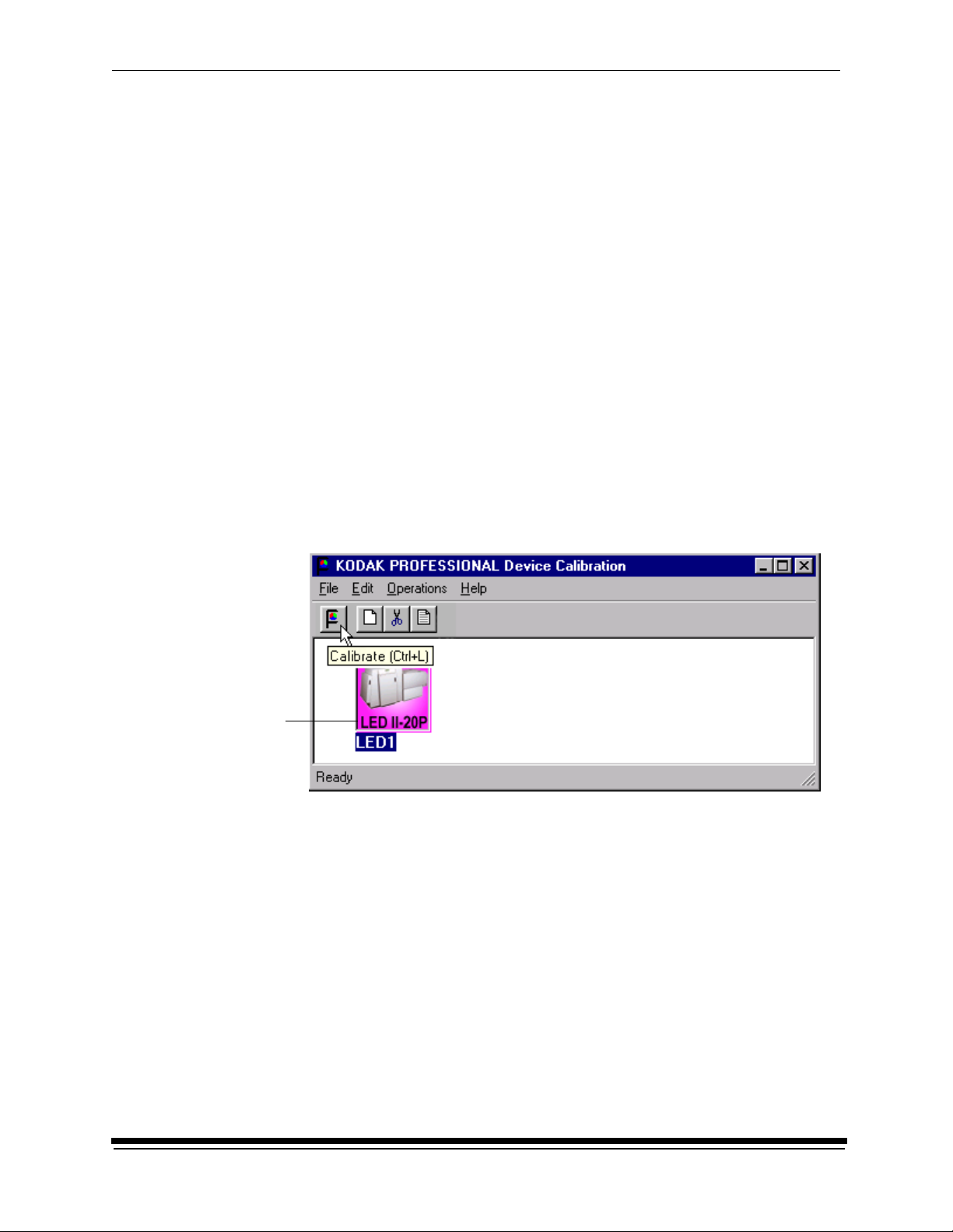
1. Open the KODAK PROFESSIONAL Device Calibration application.
The display shows the KODAK PROFESSIONAL Device Calibration window.
If the device you need to calibrate does not appear on the window, you need
to add a calibration device. See “Adding, Updating, and Deleting Devices” on
page 3-9.
LED Printer
icon
2. Select the icon for the LED Printer.
3. Click the Calibrate icon.
1-2 March 2001
Page 7
Calibrating the Printer
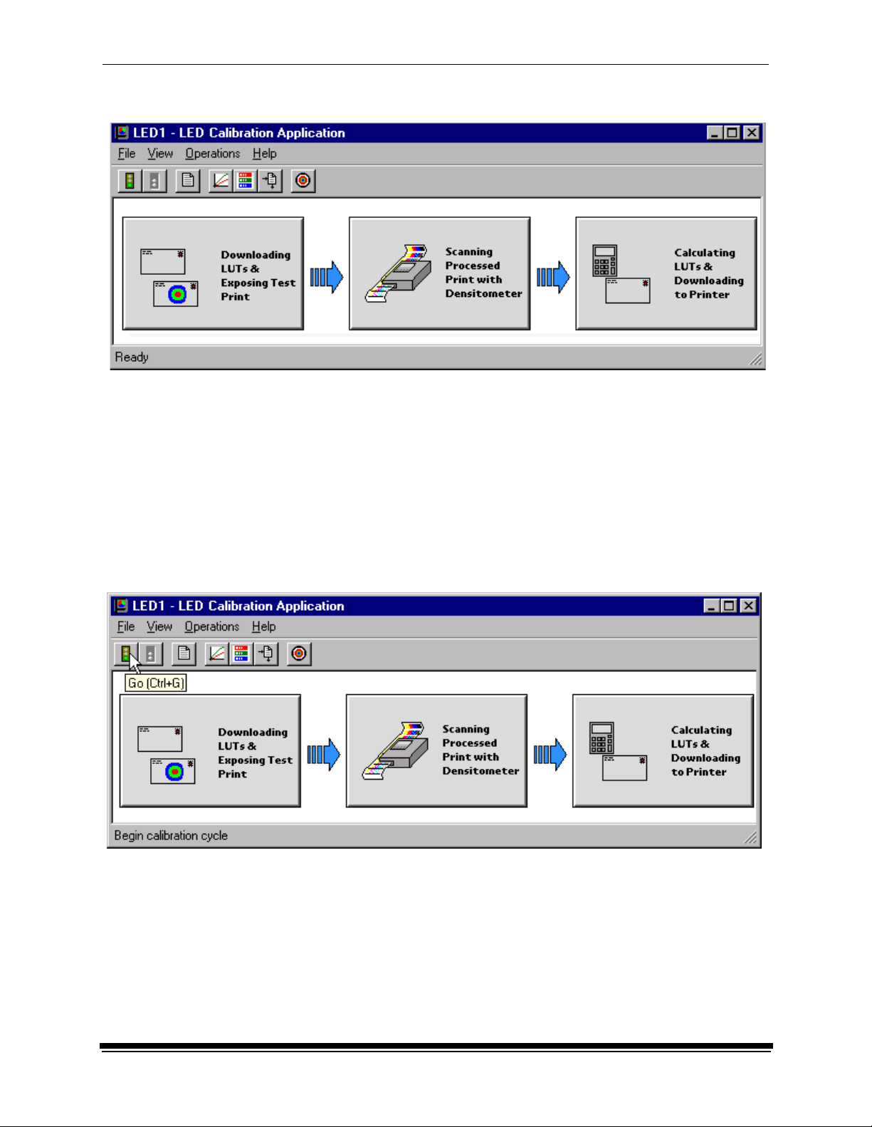
The display shows the LED Calibration Application window.
Starting the Calibration Application and Exposing a Test Target
IMPORTANT: The settings in the configuration file for the selected device
determine some of the actions and messages in this procedure.
The configuration file is specific to your lab and its operations. For
more information about the configuration file, see “Editing the
Device Configuration” on page 3-25.
1. Click Go to start the calibration cycle.
Downloading LUTs and Sending Test Print highlights.
March 2001 1-3
Page 8
Calibrating the Printer
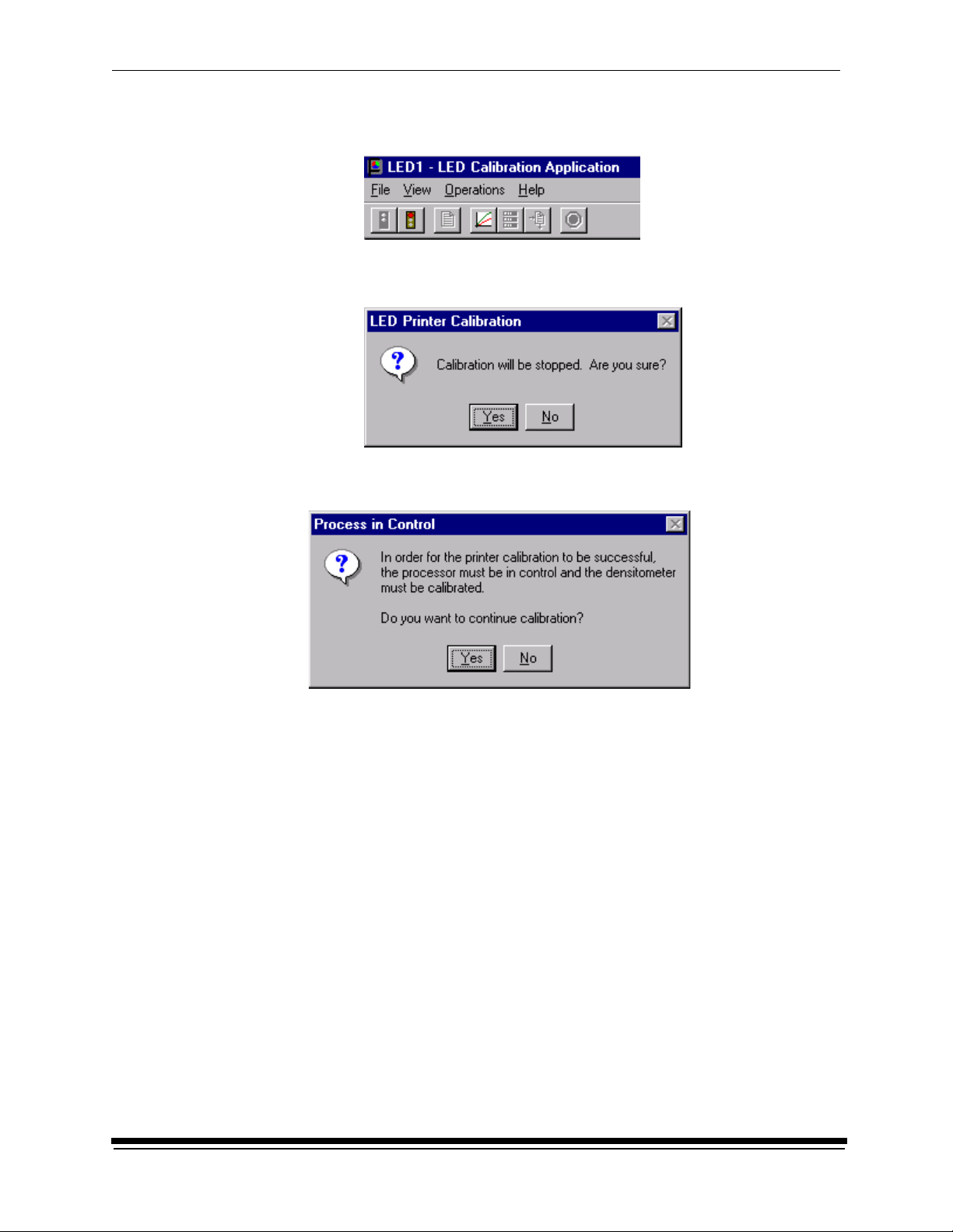
NOTE: Once the application has started, the red stoplight is active and you
can click the icon to stop the calibration procedure.
If you click the red stoplight icon, the display shows the following dialog
box.
Otherwise, if the configuration file specifies to Ask if processor is in control,
the display shows the Process In Control dialog box.
The processor is critical to printer calibration. You can calibrate the printer
only if the processor is in control.
1-4 March 2001
Page 9
Calibrating the Printer
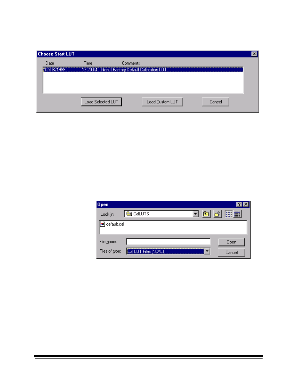
2. Click Yes.
The display shows the Choose Start LUT dialog box.
NOTE: The highlighted LUT in the dialog box above is the most recent
calibration LUT.
3. Click either Load Selected LUT or Load Custom LUT (or Cancel to cancel
the calibration process).
If you click Load Selected LUT, the system automatically down lo ads the
highlighted LUT to the printer to create a test print. When the test print has
been sent, the Scanning Processed Print with Densitometer status icon on
the LED Printer Calibration window highlights.
Continue with “Obtaining Densities” on page 1-6.
4. If you selected Load Custom LUT in step 3:
From the Open dialog box, select or type the name of the LUT file you want
and click Open.
The system automatically downloads the LUT file to the printer.
When the test print has been sent to the printer, the Scanning Processed
Print with Densitometer status icon on the KODAK LED Printer Calibration
window highlights.
March 2001 1-5
Page 10
Calibrating the Printer
Obtaining Densities
There are three methods for obtaining densities:
• from a file
• from a densitometer
• from a centralized densitometer (NT only and if the Centralized Densitometer
application is installed on your network)
The contents of the calibration configuration file determine which method you use
(see “Editing the Device Configuration” on page 3-25).
Obtaining Densities from a File
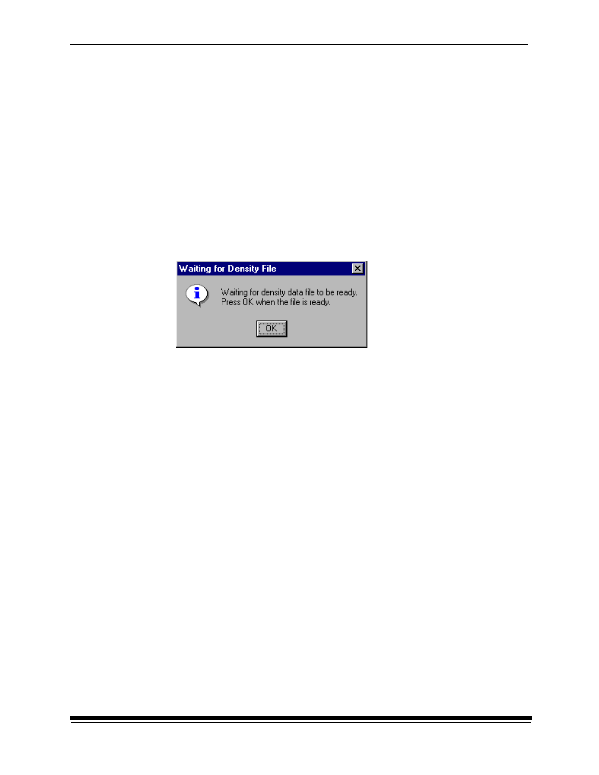
If the configuration settings include obtaining the density data from a file, the
display shows the Waiting for Density File dialog box.
If the configuration settings do not include obtaining the density data from a file,
go to either:
• “Using the Densitometer to Read Densitie s” on page 1-7
• “Obtaining Densities from the Centralized Densitometer (NT Only)” on
page 1-8
NOTE: T o create a density file, see “Creating a Density File for Use with Calibration”
on page 3-36.
1. Click OK to continue with the calibration process.
2. Go to “Completing the Calibration” on page 1-10.
1-6 March 2001
Page 11
Calibrating the Printer
Using the Densitometer to Read Densities
NOTE: For LED Gen I devices, you read only one neutral strip.
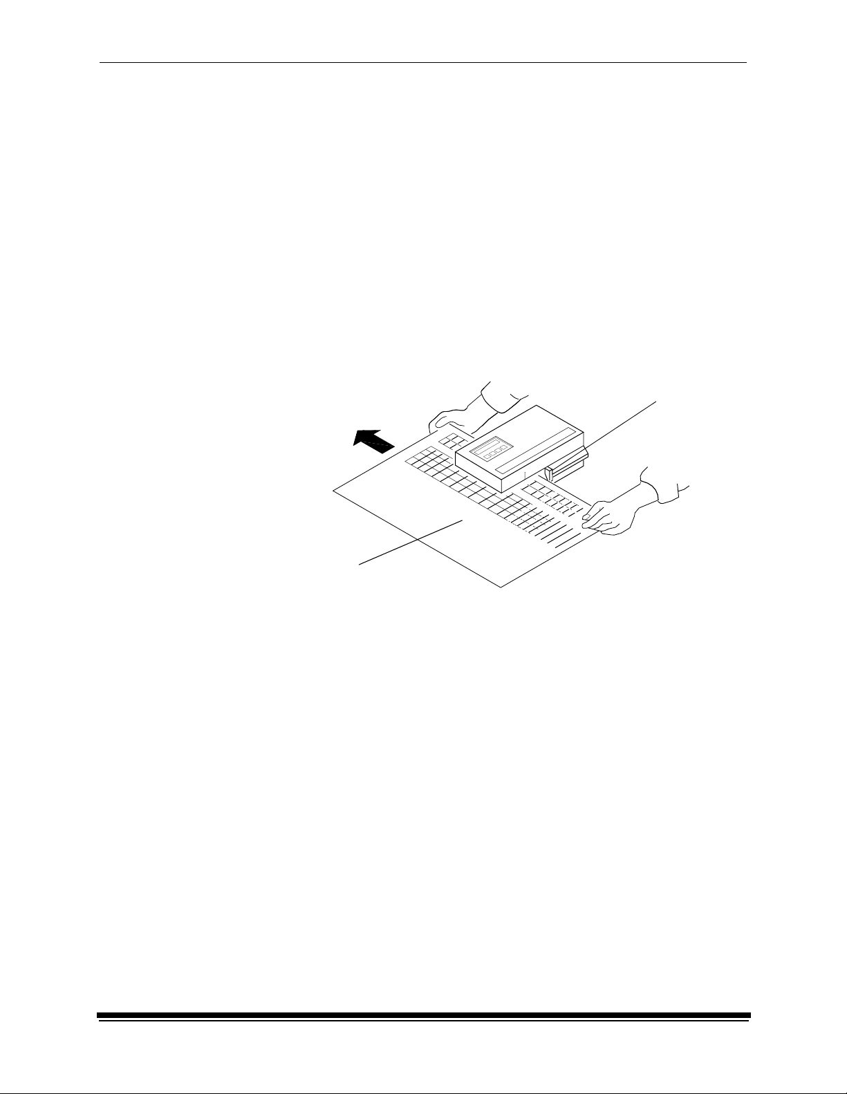
Do the following to scan the neutral (gray) patches on the processed test print into
the densitometer (refer to your densitometer manual for detailed instructions on
using the densitometer):
1. Slide the lever on the densitometer to position 15. Align the edge of the test
print with the lever on the densitometer. Gently feed the test print through the
densitometer to scan the patches labeled “even”.
2. Slide the lever on the densitometer to position 20. Align the edge of the test
print with the lever on the densitometer. Gently feed the test print through the
densitometer to scan the patches labeled “odd”.
3. Slide the lever on the densitometer to position 30. Align the edge of the test
print with the lever on the densitometer. Gently feed the test print through the
densitometer to scan the patches labeled “both”.
Lever
Test print
If the test print is read successfully, several messages will appear in the status
bar; the final message indicates that the densitometer values have been
successfully received. Go to “Completing the Calibration” on page 1-10.
If the test print is not read successfully, refer to Section 2, Troubleshooting.
March 2001 1-7
Page 12
Calibrating the Printer
Obtaining Densities from the Centralized
Densitometer (NT Only)
NOTE: For more information about installing and using the Centralized
Densitometer Application, see Section 4, Installing and Using the
Centralized Densitometer Application.
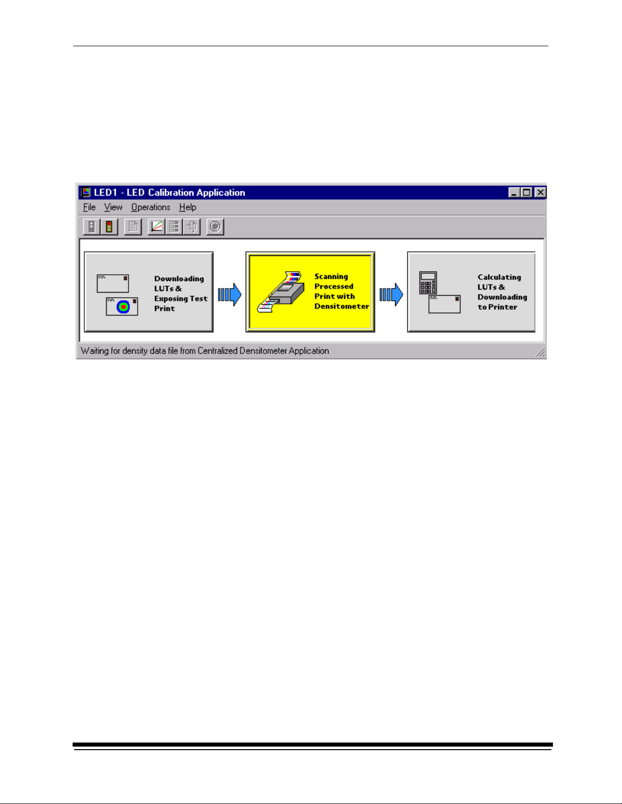
If the configuration settings include obtaining the density data from the centralized
densitometer application, the status bar shows a message.
1. Open the Centralized Densitometer Application.
1-8 March 2001
Page 13
Calibrating the Printer
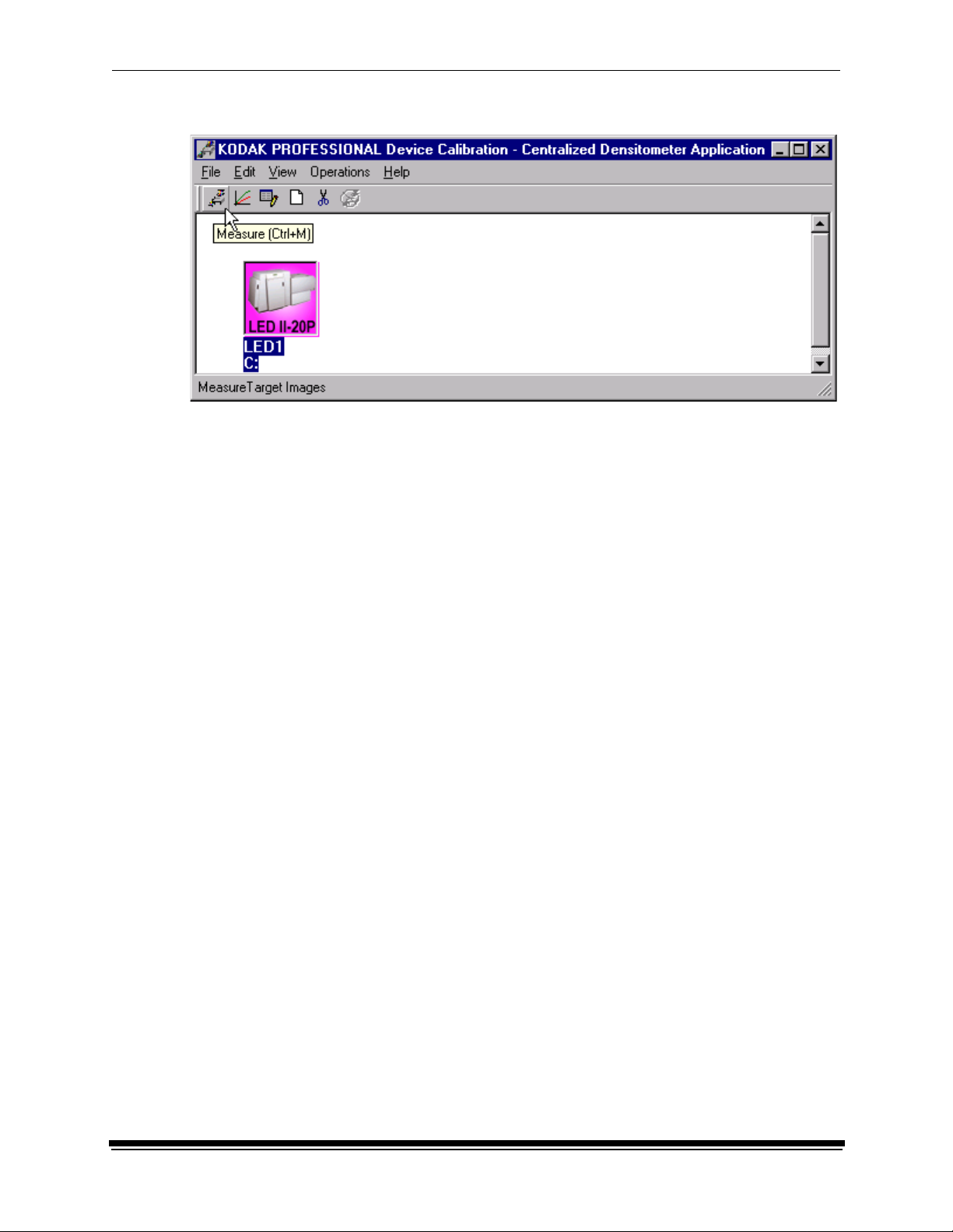
The display shows the window for the Centralized Densitometer Application.
2. Highlight the device.
3. Click Measure (or select Operations->Measure) to measure the target
images.
4. At the densitometer, measure the densities (see “Using the Densit ome ter to
Read Densities” on page 1-7).
When the densities are measured, the status bar on the Centralized
Densitometer Application window shows “Ready.”
The density measurements are automatically sent to the LED printer’s host
computer.
Continue with “Completing the Calibr at ion .”
March 2001 1-9
Page 14
Calibrating the Printer
Completing the Calibration
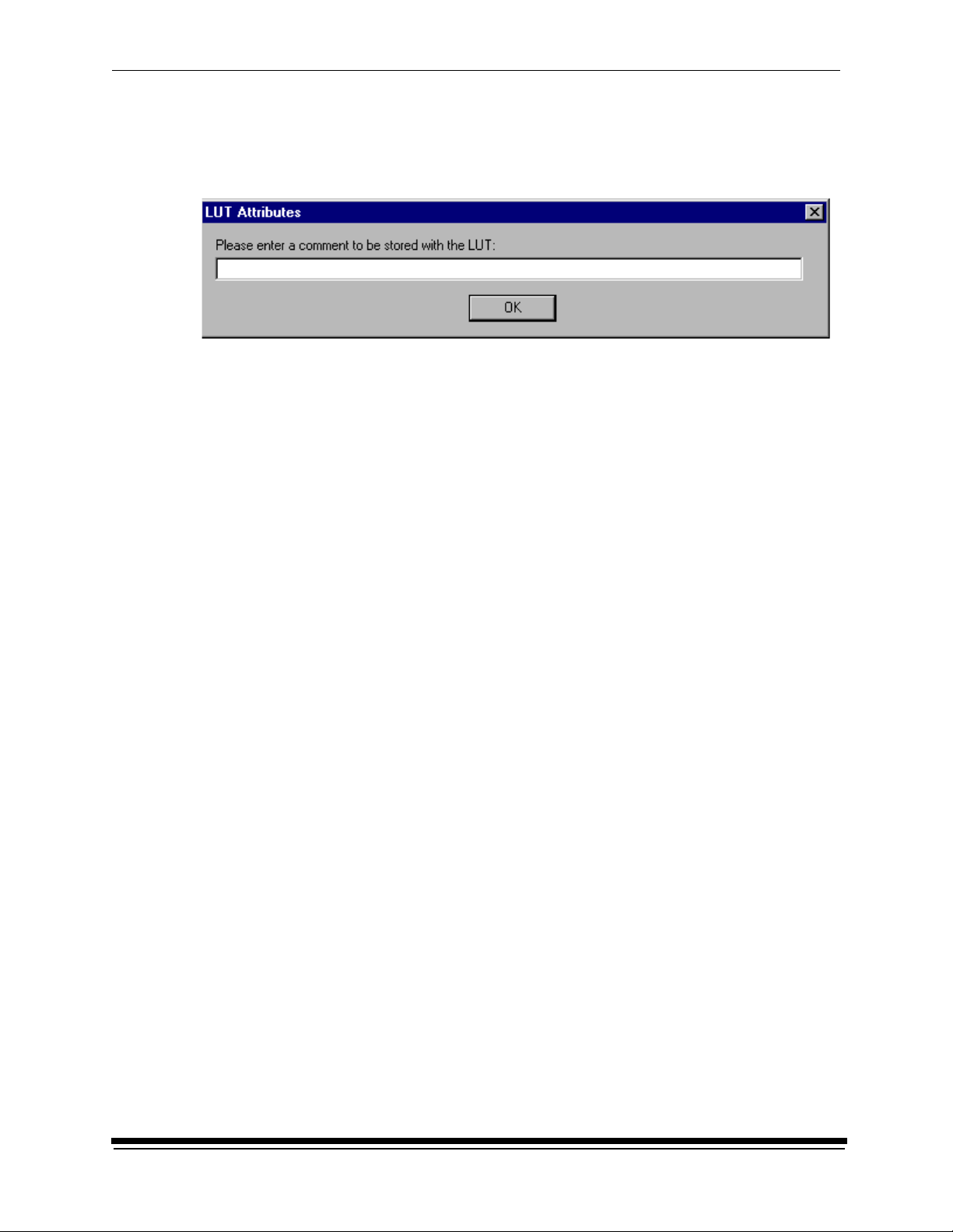
1. If calibration is in tolerance, the display shows the LUT Attributes dialog
box.
a. Type a name or comment in the dialog box. The comment you enter will
appear on the Send LUT to Printer dialog box to identify the LUT file with a
name that is meaningful to you (up to 75 characters).
b. Click OK.
The new printing LUT is calculated and downloaded. The status bar shows
“Calibration Complete.”
2. If calibration is out of tolerance, it may be necessary to run four or more
iterations of the calibration cycle to achieve a successful calibration.
1-10 March 2001
Page 15
Calibrating the Printer
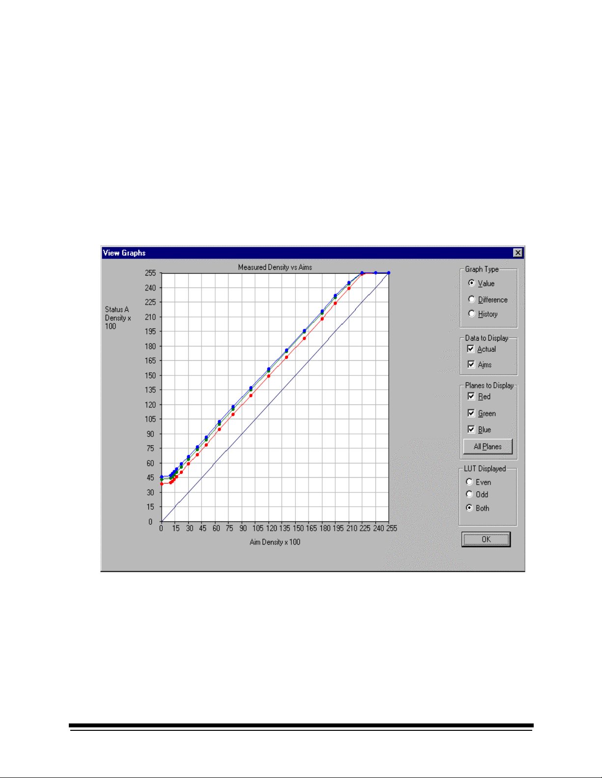
If the print densities are out of tolerance, the display shows a graph that
allows you to select the type of data and planes that you want to see
displayed.
a. Click OK.
March 2001 1-11
Page 16
Calibrating the Printer
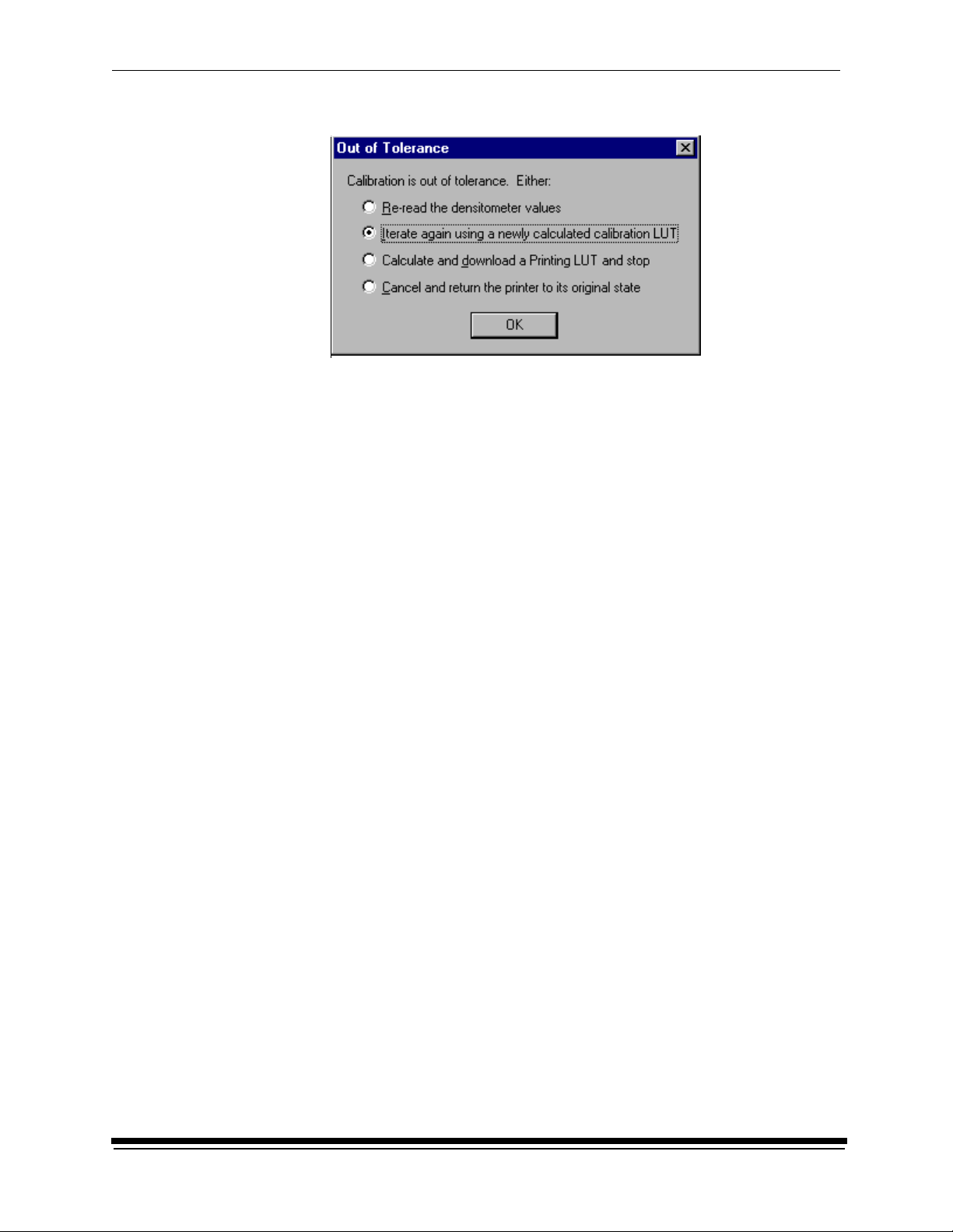
If specified in the configuration file, the display shows a list of options.
Re-read the densitometer values is most useful when the graphs show
an unusual plot. Rereading the test print lets you validate the graph, then
returns you to the Out of Tolerance dialog box.
Iterate again using a newly calculated calibration LUT allows you to
keep printing test prints with the newly created LUT without having to save
the LUT table.
Calculate and download a printing LUT and s top: When you select this
option, the LUT is calculated and the file is saved with the creation date
and time as its name.
Cancel and return the printer to its original state saves nothing. Any
corrupted data created after you saved the last time is thrown away.
b. Select one of the four options to try to complete the calibration
successfully.
1-12 March 2001
Page 17
This section describes the problems that you may occasionally have when using:
• the KODAK Device Calibration Software and the Calibration Software for the
KODAK PROFESSIONAL LED II Printer
• the X-RITE DTP36 Densitometer
Calibration Graph
The graph below is an indication that the calibration performed was out of
tolerance.
2 Troubleshooting
This may be result from invalid densitometer readings. It is necessary to perform
another calibration cycle if you see a graph that looks like the one above.
March 2001 2-1
Page 18
Troubleshooting
Calibration Errors
Numeric Calibration Error Codes
Code Status Message Possible Cause/Subsystem Possible Solution
1 The following file is
locked:_filename_.
2 The following file is
protected:_filename_.
3 The following file was not
found:_filename_.
4 Error:_oserror_occurred
during operation:_operation_
on file:_filename_.
5 The following file is in an
incorrect format:_filename_.
6 The following file already
exists:_filename_.
7 There is not enough space to
create:_filename_.
8 There are too many files to
open _filename_.
9 You do not have permission
to open file _filename_.
The system is trying to access a
file that is currently in use.
The system is trying to access a
protected file.
The system was trying to access
a file that it could not find.
An operating system error
occurred.
The file does not conform to the
application specification.
The system is trying to save to a
file that already exists.
The system is trying to save a file
but there is not enough disk
space.
Too many files are open. Close some files and or
The file permission is invalid. Rerun the application.
Close any other applications that
may be accessing the file.
Change the protections on the file
to grant access to the user.
Verify that the filename on one of
the configuration dialog windows i s
correct.
• Rerun the application.
• Reboot the operating system
Verify the file format.
• Delete the existing file.
• Change the filename.
Remove any unnecessa ry fil es to
increase free disk space.
applications.
10 Error copying print LUT to
DP2 folder (can’t open
_filename_.
2-2 March 2001
The folder doesn’t ex is t o r is readonly.
Modify the protection on the folder.
Page 19
Troubleshooting
Code Status Message Possible Cause/Subsystem Possible Solution
11 Error creating DP2 LUT
folder
101 No response from
device:_devicename_.
102 Device not
found:_devicename_.
103 The following device is
indicating it is not
ready:_devicename_.
104 The following device is
busy:_devicename_.
105 The following device is not a
TTY port:_devicename_.
106 The following device is
closed:_devicename_.
107 No data on
device:_devicename_.
A folder of the same name may
exist.
The device is not responding to
the system.
The system was trying to access
a device that it could not find.
The device is not ready. Wait several minutes and try the
The device is busy. Wait several minutes and try the
The port name in the
configuration file do es no t re fer t o
a valid serial port.
The serial port closed during
system reading.
No data is available for the
system to read on the serial port.
Change the selected folder name.
Verify tha t the dev ic e i s c onn ec ted
and on-line.
Verify that the device n ame on on e
of the configuration dialog
windows is correct.
activity again.
activity again.
Change the port name in the
configuration file to a valid serial
port.
• Verify that no other application
is accessing the port.
• Restart the application.
• Verify that the densitometer is
connected correctly.
• Restart the application.
108 Error:_oserror_occurred
during operation:
_operation_ on device:
_devicename_.
109 Invalid Device ID:
_devicename_.
An operating system error
occurred.
A new device was created with an
incorrect device ID.
• Rerun the application.
• Reboot the operating system
• If problem continues, call for
service.
Edit the device ID to reflect the
correct device ID.
March 2001 2-3
Page 20
Troubleshooting
Code Status Message Possible Cause/Subsystem Possible Solution
110 Unable to perform operation:
_operation_
Status Message:_statmsg_
Error Message:_errmsg_.
111 There is insufficient memory
for the requested operation
on device:_devicename_.
112 A communications time-out
occurred during operat ion on
device:_devicename_.
113 A device driver for the
following device c ould not b e
found:_devicename_.
114 An error occurred during
communications to the
following device:
_devicename_.
115 An operation error occurred
during communications to
the following device:_
devicename_.
An unknown device error
occurred.
The application does not have
enough memory to complete the
operation.
The connection between the
printer and host computer was
lost.
The application could not find the
necessary device software to
communicate with the printer.
• The cable between the printer
and the host computer is worn.
• One or more of the
connections between the
printer and the host computer
has malfunctioned.
• The cable between the printer
and the host computer is worn.
• One or more of the
connections between the
printer and the host computer
has malfunctioned.
Use the information in the status
message and error message to
resolve the device error.
Close the other applications and
unnecessary windows.
Check that all cables are properly
connected.
Make sure that the Calibration
Application and ASPI SCS I de vice
driver are installed correctly.
• Check that all cables are
properly connected.
• Check the cables and
connections between the printer
and the host computer for wear
and if necessary, replace them.
• Check that all cables are
properly connected.
• Check the cables and
connections between the printer
and the host computer for wear
and if necessary, replace them.
116 A software warning has be en
issued by the following
device: _devicename_ Error
Message: _errmsg_
A software error has occurred on
the printer.
Resolve printer error condition.
2-4 March 2001
Page 21
Troubleshooting
Code Status Message Possible Cause/Subsystem Possible Solution
117 A software error has been
detected by the following
device: _devicename_ Error
Message: _errmsg_
118 A SCSI ID for the following
device was not found:
_devicename_.
119 The wrong SCSI ID was
specified for the following
device: _devicename_.
120 This device has been setup
for the wrong model of
printer: _devicename_.
121 Unable to read ST A T US from
device: _devicename_.
122 The se lected LUT contains
data that exceeds the limits
of this printer .
201 An error occurred while
trying to allocate memory.
202 The following parameter is
invalid:_parametername:
_parametervalue_.
An error has occurred on the
printer.
SCSI driver not found. Reinstall the SCSI driver on host
SCSI ID is incorrect. Set the Target SCSI ID to the
The chosen device has not been
found.
Unable to see the printer. Check SCSI cable connections.
Trying to send a 12-bit LUT to a
10-bit printer.
The system is trying to allocate
memory; however, no memory is
available.
An internal error occurred wi th the
software.
Resolve printer error condition.
computer.
printer SCSI ID.
Verify chosen device matches the
printer model.
Select a 10-bit LUT file.
Close any unnecessary
applications.
• Restart the application.
• If problem continues, call for
service.
203 The function is not support ed
by the class.
204 This function has not been
implemented.
An internal error occurred wi th the
software.
An internal error occurred wi th the
software.
• Restart the application.
• If problem continues, call for
service.
• Restart the application.
• If problem continues, call for
service.
March 2001 2-5
Page 22
Troubleshooting
Code Status Message Possible Cause/Subsystem Possible Solution
205 Must enter the following
field:_field_.
301 The following key was not
found: _key_.
302 The following grouper was
not found:_grouper_.
303 The call depends on a
current grouper, but the
current grouper has not be en
set.
501 An error occurred while
applying the data.
601 A bad count was entered.
The expected count
was:_count_.
The operator left a configuration
field blank.
• An internal error occurred with
the software.
• One of the files was edited
manually and a key was
changed.
• An internal error occurred with
the software.
• One of the files was edited
manually and a grouper was
changed.
An internal error occurred wi th the
software.
• A file was edited manually and
an incorrect number of rows
was entered.
• An internal software error
occurred.
Enter information in the blank
configuration field.
• Restart the application.
• Restore the key to its previous
value.
• If problem continues, call for
service.
• Restart the application.
• Restore the grouper to its
previous value.
• If problem continues, call for
service.
• Restart the application.
• If problem continues, call for
service.
• Manually enter the correct
number of rows in the file.
• If problem continues, call for
service.
602 An error occurred during the
calculation process.
701 Patch _patch_, column
_column_, value _value_ is
beyond tolerance
_tolerance_ for aim _aim_.
An internal error occurred wi th the
software.
A density patch was out of
tolerance.
• Restart the application.
• If problem continues, call for
service.
Perform another calibration cycle.
2-6 March 2001
Page 23
Troubleshooting
Code Status Message Possible Cause/Subsystem Possible Solution
702 Patch _patch_ has a spread
of _spread_ which is out of
range _range_.
703 CalT ol eranceFile can on ly be
initialized once.
704 CalToleranceFile::
initialize must be called first.
801 Could not find row:_row_. An internal error occurred with th e
802 Could not find
column:_column_.
803 Could not find element -
column:_column_.
row:_row_.
804 Row value was not set
before using.
805 Column value was not set
before using.
The spread between colors for a
given density patch is out of
tolerance.
An internal error occurred wi th the
software.
An internal error occurred wi th the
software.
software.
An internal error occurred wi th the
software.
An internal error occurred wi th the
software.
An internal error occurred wi th the
software.
An internal error occurred wi th the
software.
Perform another calibration cycle.
• Restart the application.
• If problem continues, call for
service.
• Restart the application.
• If problem continues, call for
service.
• Restart the application.
• If problem continues, call for
service.
• Restart the application.
• If problem continues, call for
service.
• Restart the application.
• If problem continues, call for
service.
• Restart the application.
• If problem continues, call for
service.
• Restart the application.
• If problem continues, call for
service.
806 Error deleting row:_row_. An internal error occurred wi th the
software.
807 Element at row:_row_;
column:_col_
value:_val_ failed audit.
An input file had incorrectly
formatted data in it at the loca tion
indicated.
• Restart the application.
• If problem continues, call for
service.
• Verify that you are using the
correct file.
• Edit the file and correct the
format.
March 2001 2-7
Page 24
Troubleshooting
Code Status Message Possible Cause/Subsystem Possible Solution
910 Configuration file
field:_filename_is invalid.
Calibration will be cancelled.
911 Error_errcode_occurred.
Processing stopped.
919 Error occurred preparing to
handle exit from Kodak
Device Calibration. Will not
perform cleanup at exit.
921 Unable to return the printer
to its original state. Fix
printer problem and recalibrate.
922 There is already a printer
open. Please close the op en
printer first.
923 An error occurred during the
loading of a printer. Please
check to make sure the file
chosen was of the correct
type and/or format.
The user entered an incorrect
value in a configuration file.
An internal error occurred wi th the
software.
An internal error occurred wi th the
software.
The application was trying to
cancel but received an error when
sending the original LUT back to
the printer.
User tried to open a printer when
the printer was already open.
An error occurred during the
loading of a printer.
• Enter the correct value.
• Reinstall the application.
• If problem continues, call for
service.
Restart the application.
Restart the application.
Printer is in an unknown state.
Correct any printer problems and
restart the application.
Close the open printer.
Check that the file chosen was the
correct format or type.
924 No printer loaded. The operator has not yet opened
a printer.
941 The height and width values
do not agree with the size of
the target file.
942 Unable to configure
densitometer. Densitometer
configuration file may be
corrupt or lost.
The specified size does not match
the file size.
The file CalDevDensGen2.cfg is
corrupt or lost.
Open a printer.
Enter the correct file size.
Restart the application. If problem
continues, call for service.
2-8 March 2001
Page 25
Troubleshooting
Code Status Message Possible Cause/Subsystem Possible Solution
1003 Unable to load default
configuration file:_filename_.
1004 Unable to set values
in new configuration file.
1005 Unable to save configu rati on
file:_filename_.
1006 Configuration file fiel d:_field_
is invalid.
1007 Unable to remove
directory:_directory_.
1101 Density DMIN/DMAX points
are invalid.
1102 Density data is not
monotonic increasing.
1 103 Exceeded maximum number
of allowable data errors.
The default configuration file was
deleted or renamed or moved.
An internal error occurred wi th the
software.
The system is trying to save a file
but there is not enough disk
space.
The user entered an incorrect
value in a configuration file.
The user does not have the
authority to update the directory.
Density po ints are invalid. Reread density values on
Density da ta is invalid. Reread density values on
Density da ta is invalid. Reread density values on
Restore the file manually or
reinstall the software.
Restart the application.
Remove any unnecessa ry fil es to
increase free disk space.
• Enter the correct value.
• Reinstall the application.
Verify that the user has update
authority on the directory.
densitometer or make a new
calibration print.
densitometer or make a new
calibration print.
densitometer or make a new
calibration print.
1104 Asymmetric Density
Groupings are invalid.
1201 Unknown response from
densitometer.
Density da ta is invalid. Reread density values on
densitometer or make a new
calibration print.
During initialization , the
application received an unknown
response from the densitometer.
Verify that the baud rate of the
densitometer matches that of the
applications configuration.
March 2001 2-9
Page 26
Troubleshooting
Code Status Message Possible Cause/Subsystem Possible Solution
1202 Error:_error_from
densitometer.
1203 Error: Number of patches
seen by densitometer is
incorrect.
1300 Values have not been loaded The matrix file is missing. Create a new device.
1301 Data or Matrix files have not
yet been loaded
1302 Data cannot be saved, must
first apply the matrix
An unexpected error was returned
from the densitometer.
Unable densities on densitometer. Try adjusting frame counts or
The matrix file is missing. Create a new device.
The matrix file is missing. Create a new device.
Calibrate the densitometer. If the
problem continues, check the
manual for the densitometer.
reread the density patches on the
densitometer.
2-10 March 2001
Page 27

Troubleshooting
Non-Numeric Calibration Error Messages
Error Message Possible Cause/Subsystem Possible Solution
An underrun error occurred during
communications to the following
device.
An UNKNOWN error occurred
during communications to the
following device.
Device not found. The host computer attempted to
Invalid Device ID. The host computer attempted to
The following device is busy. The printer at the specified SCSI ID
• The cable between the printer
and the host computer is worn.
• One or more of the connections
between the printer and the host
computer has malfunctioned.
An unknown error occurred in the
application.
contact the printer at the specified
SCSI ID but did not get a response.
contact the printer at the specified
SCSI ID but did not get a response.
is busy.
• Check that all cables are pro perl y
connected.
• Check the cables and
connections between the printer
and the host computer for wear
and, if necessary, replace them.
• Restart the calibration application.
• If the problem continues, make
sure that the Calibration
Application and ASPI SCSI
device driver are installed
correctly.
• Make sure that the printer is
turned on and is on-line.
• Make sure that the Calibration
Application and ASPI SCSI
device driver are installed
correctly.
Make sure that the printer is turned
on and is on-line.
Check that all cables are properly
connected.
The following device is closed. The connection between the printer
and host computer was lost.
Check that all cables are properly
connected.
March 2001 2-11
Page 28

Troubleshooting
Densitometer Errors
Code Message Explanation
<01> BAD_COMMAND The densitometer does not recognize a command.
<02> PRM_RANGE_ERROR One or more data or address parameters is out of range. See the
command guide for parameter limits.
<03> DISPLAY_OVERFLOW_
ERROR
<04> MEMORY_OVERFLOW_
ERROR
<05> INVALID_BAUD_RATE The parameter included with the BR command was invalid. Valid
<06> INVALID_PHOTO_STRIP The specified photographic control strip does not exist.
<07> TIMEOUT The time interval between characters has exceeded 5 seconds.
<08> PRM_SYNTAX_ERROR. An invalid character was found in the command string.
<09> INVALID_PASS The requested pass does not exist for the currently stored strip (e.g.,
<0a> INVALID_STEP The requested step does not exist for a given pass in the cu rrent ly s tore d
<0b> NO_DATA_AVAILABLE Data was requested but no data is stored in memory.
<0c> MISSING_PARAMETER One or more required parameters was omitted.
<10> LAMP_MARGINAL The lamp output is at approximately 50% of its original brightness. Strip
An attempt was made to rea d or wri te bey ond the end of the dis play. Valid
addresses for the display range from 0x00 to 0x20 (0 to 31 decimal).
An attempt was made to read or write beyond the end of the external
RAM within the densit ometer. Valid addresses for t he external RAM range
from 0x0000 to 0x7fff (0 to 32767 decimal).
parameters are 06 (1200), 0C (2400), 18 (4800), 30 (9600), and 60
(19200).
specifying pass 5 for a 4-pass strip).
strip (e.g., specifying step 25 or step 0 on a 21-step pass).
readings can still take place, but to maintain proper accuracy and
repeatability, replace the lamp as soon as possible.
2-12 March 2001
Page 29

Troubleshooting
Code Message Explanation
<11> LAMP_FAILURE The lamp is either burned out or its output is at a level too low for
acceptable readi ngs. The densitome ter will not read strip s until the lam p is
replaced and the densitometer is re-calibrated.
<12> STRIP_RESTRAINED During calibration, the calibration s trip was hel d or restrai ned as it pas sed
through the unit. Do not hold the strip as it is reading and make sure the
read path is clear of any foreign matter.
<13> BAD_CAL_STRIP During calibration, the calibrat ion stri p was un recogn izabl e. The s trip ma y
have been inserted backwards, upside down, or held so that it slipped on
the internal rollers. This also may be an indication that the strip needs to
be replaced.
<14> MOTOR_ERROR During calibration, a problem was detected with the drive motor. This can
occur if the strip is held back while reading.
<20> INVALID_READING The strip just read was not recognized by the densitometer.
<21> WRONG_COLOR After a strip reading, the step wedge just read was not the color specified
for that pass or strip as defined in the densitometer editor menu.
<23> NEEDS_CALIBRATION The calibration check that was done immediately after reading a strip
indicated that the unit needs calibration. This occurs when the reading
taken from the opal glass after the strip exits the unit differs from the
reading taken during calibration by more than the internal tolerance
(default is 0.1 X, Y, or Z). The tolerance can also be changed by the RCI
command CC (Check Cal tolerance).
<26> NO_VALID_DATA The measure type is set to CONT and the strip that was read contained
nothing but base material. Base material is defined as measuring less
than 0.5D in the visual channel. For negative (black) based materials,
base material is defined as me asurin g less than twice the reflect anc e of a
measurement taken near the trailing edge of the strip. the densitometer
uses a measurement taken at about 0.25 inches from the trailing edge of
the strip to determine i f it is posi tive o r negati ve bas ed. Any m easu rement
greater than 10% reflectance is considered positive based; anything else
is considered negative based.
March 2001 2-13
Page 30

Troubleshooting
Code Message Explanation
<27> BAD_PATCH If the Pattern Recognition comparison window is set to 0 or 1, this error
may result when a single patch on the strip is bad due to dirt, smears,
creases, etc. (See expl anation of CW command for more informat ion.)
<30> BAD_STRING_LENGTH A strip definition string received as part of the DS (Define Strip) R CI
command did not contain the correct number of characters.
<31> BAD_CHARACTER A non-printable character was received in one of the name fields (strip
name or pass name). Print abl e cha rac ters are in the range 0x20 to 0x7E,
inclusive.
<32> BAD_MEAS_TYPE The value for the measure type field was greater than 3. Valid values are
0 through 3.
<33> BAD_COLOR The value for the color field was greater than 9.
<34> BAD_STEPS The value for the number of steps was greater than 72.
<35> BAD_STOP_LOCATION The value for t he guide setting was less than 4 or greater than 30.
<36> BAD_OUTPUT_TYPE The value for the output type was greater than 5.
<37> MEMORY_ERROR The definition could not be stored.
<38> BAD_N_FACTOR The n-factor (used in Dot calculations) is either less than 0500 (0.500) or
greater than 4500 (4.500).
<39> STRIP_DOESNT_EXIST The SD command was issued and the requested strip does not exist.
<3A> BAD_MIN_MAX_VALUE The value for the min/max field was greater than 4.
<40> BAD_SERIAL_NUMBER An attempt was made to redefine one of the stored serial numbers with a
number containing one or more invalid digits.
2-14 March 2001
Page 31

3 Using Additional Calibration Features
The topics covered in this section include:
• Installing the Calibration Software
• An overview of the Kodak Professional Dev ice Cali br ati on Software
• Advanced Features of the LED II Calibration Software
• Installing the Densitometer
IMPORTANT: For the step-by-step procedure to calibrating the printer, see
Section 1, Calibrating the Printer.
Installing the Calibration Software
Installing the software includes installing both the Kodak Professional Device
Calibration Software (which manages the calibration of multiple Kodak devices)
and the Calibration Software for the Kodak Professional LED II Printer 20P/20R.
Y ou can install the software either from a supplied CD or by downloading from the
Kodak web site.
System Requirement s
MACINTOSH Systems
• Power MACINTOSH System 7.5 or above
• Minimum of 35 MB free disk space
• 608 K free disk space for each of as many as six configured devices
• 256 colors at 640 x 480 spatial resolution
• CD ROM Drive
WINDOWS NT Systems
• 100 MHz PENTIUM Processor
• 64 MB Main System Memory
• VGA Monitor (640 x 480 spatial resolution)
• CD ROM Drive
March 2001 3-1
Page 32

Using Additional Calibration Features
Installation Procedure
1. If you are installing the software from the supplied CD-ROM:
a. Place the CD in your CD-ROM drive.
b. When the Browser is displayed, select LED Printer.
2. If you are downloading the installation files from the Kodak web site, go to
http://www.kodak.com/global/en/service/printers/led2Printer/led2Printer.shtml.
3. Under the heading Product Support, select Drivers, Softwa re and F irmwa re.
4. Select Calibration Utilities.
5. Under the heading Download File, select KODAK PROFESSIONAL Device
Calibration.
The display shows the Save As dialog box.
6. Either accept the default path and file name or select another path and file
name and save the file.
3-2 March 2001
Page 33

Using Additional Calibration Features
NOTE: The installation is similar for NT and Macintosh systems. When the
instructions say, for example, click Next or Install, the first option is for NT
systems and the second is for Macintosh systems.
CAUTION: T o avoid possible damage, do not connect or disconnect the cable
between your host computer and the printer when either device
is powered up.
7. Open the installation file (KODAK PROFESSIONAL Device Calibration.exe).
The display shows a splash screen for KODAK PROFESSIONAL Device
Calibration and a Setup message.
8. After the Welcome screen is displayed, click Next or Continue.
9. For Macintosh systems only, read the readme information, then click
Continue.
10. Read the license agreement.
• To accept the terms and continue the installation, click Yes or Agree.
• Or, to cancel the installation, click No or Disagree.
11. For NT systems only, read the readme information, then click Next.
12. Select the installation type:
For NT systems, select one of the following:
NOTE: The Compact option is not supported.
• Typical includes Device Calibration Applications for the Kodak
Professional LED Printer and for the Kodak Professional
Digital Mutliprinter, plus the Linearization Calibration
Application for the Kodak Professional RFS 3570+ (Speed
Up) Film Scanner
• Custom allows you to choose specific features for the application you
choose to install, including the Centralized Densitometer
Application; for the LED Printer, you may choose to install
either Gen I or Gen II.
For Macintosh systems, select Easy Install.
March 2001 3-3
Page 34

Using Additional Calibration Features
13. Click Next to install the software on your system.
The display shows a dialog box for you to designate where to install the
calibration software.
14. Either accept the default path and folder or select another path and folder.
15. Click Finish or OK.
NOTE: For NT systems, the dialog box gives you the option of reading the
16. If you installed the software from a CD-ROM, remove the CD and store it in a
safe place.
readme file associated with your installed applications.
3-4 March 2001
Page 35

Using Additional Calibration Features
About the Kodak Professional Device Calibration Software
The Kodak Professional Device Calibration software manages and launches
customized calibration software applications, including the calibration software for
the LED 20P and 20R printers.
Application Window Definitions
The window below and the tables that follow define the application window for the
KODAK PROFESSIONAL Device Calibration Software.
Tool bar
Menu bar
Device icon
(this is displayed
when you add
a calibration
device)
Title bar
Status bar
Window Area Description
Title Bar Contains the application name, “KODAK PROFESSIONAL D evice Calibration”
Menu Bar Contains selectable menu items
Tool Bar Contains the user selectable menu choices and is activated by a shortcut keystroke or
by a mouse pointer and left mouse button
Client Area Contains the icons that represent devices available for calibration
Device Icon Represents a device that can be calibrated
Status Bar Displays messages to the user to indicate actions that are occurring or the status of
the occurring action and the currently selected device
Client area
March 2001 3-5
Page 36

Using Additional Calibration Features
The table below defines the functions and their corresponding icons on the main
window of the Device CalibrationSoftware.
Menu
Access
Function Icon/Key Availability Description
Operations C
File N
alibrate
ew
Edit Cut
File E
dit
NT Systems: Ctrl+L
MAC Systems: +L
NT Systems: Ctrl+N
MAC Systems: +N
NT Systems: Ctrl+X
MAC Systems: +X
NT Systems: Ctrl+E
MAC Systems: +E
When the
device is
selected
Passes control to calibration
software for the device; doubleclicking on a device icon
performs the same action
Always Displays Create a New Device
dialog box; adds a device to
control area
When a
calibration
device is
selected
Removes object from control
area. All history data files
(including log data, LUT files
etc.) will be deleted for this
device. The display shows a
confirmation dialog box so you
cancel the action.
Always If no object is selected, Edit
Application Configuration dialog
box is displayed. If an object is
selected, Update a Device
Registry dialog box for that
device is displayed.
File
MAC Systems:
Quit
NT Systems:
NT Systems: Ctrl+Q
MAC Systems: +Q
Always Exits application
Exit
Help Product Info NA Always Displays Product Information
dialog box
3-6 March 2001
Page 37

Using Additional Calibration Features
Starting the Device Calibration Software
Load the Calibration Software according to the table below. (If needed, see
“Installing the Calibration Software” on page 3-1.)
MACINTOSH Systems NT Systems
1. Open the folder that cont ai ns th e fil es fo r the
calibration application.
2. Click the icon for KODAK PROFESSIONAL
Device Calibration.
Editing the Log Settings
Your Device Calibration application has specific “log settings” for the purpose of
keeping a history of the calibration. You may want to change the settings—the
type of messages written to the log file, the number of days to keep the log file,
and the name of the log file. (See also “Editing Information on the History Tab” on
page 3-30.)
T o change the log settings for the Device Calibration:
1. On the Device Calibration window, deselect all devices.
Select:
Eastman Kodak/KPRO Applications/KODAK
PROFESSIONAL Device Calibration
from the WINDOWS NT Start menu.
All devices
must be
deselected
2. Click the Edit icon or select File->Edit.
March 2001 3-7
Page 38

Using Additional Calibration Features
The display shows the Edit Configuration dialog box with the default settings:
3. Edit the device settings as needed or click Default to refresh the dialog box
with the default settings.
The log operations/settings include:
Device Setting Options
Log Type None: No logging of events or errors
Events: Log events only (status messages that are displayed on the
Errors: Log errors only
Log all actions: Log all actions
screen)
Keep log for
(days)
Enter the number of days you want to keep logged information – for up to
99 days
Log File Name Enter the name that you want to give to the log file
4. Click OK to save (or Cancel to cancel) the changes.
3-8 March 2001
Page 39

Using Additional Calibration Features
Adding, Updating, and Deleting Devices
You can:
• add new printer calibration devices
• update the name or SCSI ID (Target ID) of an existing device
• delete devices
• update the configuration files for devices
Adding a Device
1. Click the New icon or select File->New on the Device Calibr ation w indow.
The display shows the Create a New Device dialog box.
2. Enter the correct device settings. Use a unique identifying word for the device
name.
NOTES: The default SCSI ID for the printer is 5. The printer’s OCP menu
displays the current SCSI ID for the printer.
Make sure the Device Type field matches the type of printer that
is being calibrated (for example: Digital LED II 20P).
3. Click OK to accept the changes.
March 2001 3-9
Page 40

Using Additional Calibration Features
A new printer device icon is displayed on the Device Calibration window.
NOTE: If an error message is displayed, refer to Section 2, Troubleshooting.
Updating a Device
T o update the device name or the SCSI information for a device:
1. Select the device by clicking once on the device icon on the Device
Calibration window.
Device
icon
2. Click the Edit icon or select File->Edit.
3-10 March 2001
Page 41

Using Additional Calibration Features
The display shows the Update a Device dialog box.
3. Enter the correct device settings.
The options for the device settings include:
Device Setting Options
Device name Enter the name that you want to give to the device.
NOTE: The MACINTOSH platform limits the device
name to 10 characters.
SCSI Host Adapter Adapter ID on host computer
SCSI ID The SCSI ID for the device; the default is 5 for the
LED Printer
4. Click OK to save (or Cancel to cancel) the changes.
March 2001 3-11
Page 42

Using Additional Calibration Features
Deleting a Device
T o delete a device and all files associated with the device:
1. Select the device by clicking once on the device icon.
Device
icon
2. Click the Cut icon or select Edit->Cut.
The display shows:
3. Click Yes to delete the device and associated files (or click No to stop the
deletion process).
3-12 March 2001
Page 43

Using Additional Calibration Features
Advanced Features of the LED II Calibration Software
The Calibration Software for the KODAK PROFESSIONAL LED II Printer
20P/20R provides automated neutral density printer calibration and is designed to
be used without assistance from technical experts. The advanced calibr ati on
features provided by this product enable you to customize the calibration of the
printer. To use the advanced features, you should understand image science
technology and the implications of manipulating neutral density calibrations.
IMPORTANT: Printer calibration should not be mistaken for color management.
Color management is provided by software applications that are
independent of the printer and the calibration software.
Viewing Graphs
The View Graphs feature provides access to the available graphs from the most
recently completed calibr ati on .
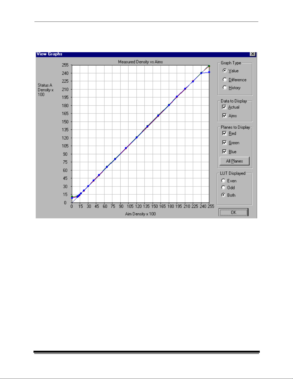
Examples of the Value, Difference, and History Graphs follow. The Value and
Difference Graphs reflect the densitometer values that were last read. The History
Graph displays the data from completed calibrations.
March 2001 3-13
Page 44

Using Additional Calibration Features
Value Graph
3-14 March 2001
Page 45
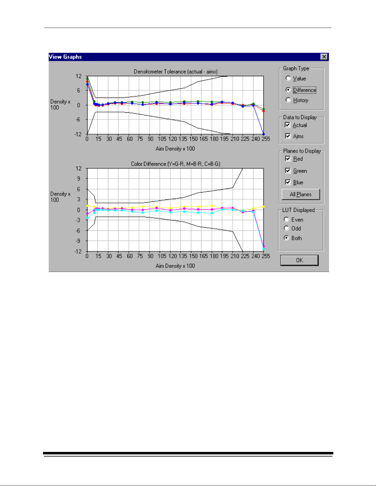
Difference Graph
Using Additional Calibration Features
March 2001 3-15
Page 46

Using Additional Calibration Features
History Graph
3-16 March 2001
Page 47

Using Additional Calibration Features
To view calibration graphs:
1. From the Device Calibration window, double-click the device for which you
want to view graphs.
The display shows the LED Calibration Application window.
2. Click the Graphs icon or select View->Graphs.
The display shows one of the graphs; typically it is the Value graph.
3. Select the Graph Type that you want to view. When the graph is displayed,
select the type of data and planes that you want to see displayed.
NOTE: The graph will be blank if the printer has not been calibrated.
March 2001 3-17
Page 48

Using Additional Calibration Features
Applying a Master Balance (NT Systems Only)
Master Balance is a method that allows you to temporarily modify printer neutral
calibration. This may be desired for customizing a particular job or correcting for a
short-term processing shift. It does not replace calibrating the printer.
1. From the Device Calibration window, double-click the device for which you
want to perform a master balance.
The display shows the LED Calibration Application window.
2. Click the Master Balance icon or select Operations->Master Balance.
3-18 March 2001
Page 49

Using Additional Calibration Features
The display shows the Master Balance dialog box.
3. Click and drag the sliders as needed for Density, Red, Green, or Blue
balance.
For Density, Red, Green, and Blue, 1 unit of change is equal to 0.01 log
exposure or 1 color correction (cc) units. For unit changes of less than one,
you can type the number directly into the edit box.
4. Click OK to accept the changes (or click Cancel to cancel the master
balance).
March 2001 3-19
Page 50

Using Additional Calibration Features
The display shows the Choose Master Balance LUT dialog box.
IMPORTANT:In the next step, do not select the default LUT.
5. Select one of the LUTs from the dialog box and click Load Selected LUT or
click Load Custom LUT and follow the prompts to load a custom LUT.
A new LUT is calculated based on the selected LUT and the input DRGB
values. The LUT is downloaded to the printer, overwriting the current LUT.
This LUT will be the current printer LUT until a new LUT is sent.
Sending LUTs
The Send LUT to Printer feature allows you to overwrite the current LUT in the
printer. You can create a valid printing LUT using an ASCII text editor. This option
sends the selected LUT to the printer, overwriting any existing LUT.
To send a LUT to the Printer:
1. From the Device Calibration window, double-click the device for which you
want to send a LUT.
3-20 March 2001
Page 51

Using Additional Calibration Features
The display shows the LED Calibration Application window.
2. Click the Send LUT icon or select Operations->Send LUT.
The display shows the Send LUT to Printer dialog box.
3. Select one of the LUTs from the dialog box and click Load Selected LUT or
click Load Custom LUT and follow the prompts to load a custom LUT. The
LUT is downloaded to the printer, overwriting the current LUT.
March 2001 3-21
Page 52

Using Additional Calibration Features
Sending Targets
The Send Target feature enables you to send any properly formatted target file to
the printer without performing a calibration. The target file must contain image
data in the format for the K oda k Pr ofe ss io nal LED II Printer 20P/20R. The format
of this file must be raw RGB pixel interleaved.
T o send a test target to the printer:
1. From the Device Calibration window, double-click the device for which you
want to se nd a test target.
The display shows the LED Calibration Application window.
2. Click the Send Target icon or select Operations->Send Target.
3-22 March 2001
Page 53

Using Additional Calibration Features
The display shows the Send Target to Printer dialog box. (The versions for
both NT and MACINTOSH Systems are shown.)
NT Systems
NOTE: Users of N T systems can click Browse to select another file name. The
display shows the Open dialog box. Select the file name, then click
Open.
March 2001 3-23
Page 54

Using Additional Calibration Features
MACINTOSH Systems
3. Enter the desired settings and click OK to save the settings (or Cancel to
keep the previous settings).
The selected test target is sent to the printer.
3-24 March 2001
Page 55

Using Additional Calibration Features
Editing the Device Configuration
The Edit Configuration feature allows you to change the printer’s calibration
configuration attributes. However, it is recommended that you use the default
settings for these attributes for most operations.
Edit Configuration consists of a set of six tabs—each with related configuration
attributes. There can be only one set of configuration attributes for the printer
calibration application at a time. If you make any changes to information on one or
more of the tabs and then click OK to save your changes, the changes will
overwrite the previous attributes used for the automated calibration.
T o edit the device configuration:
1. From the Device Calibration window, double-click the device for which you
want to change the calibration configuration.
March 2001 3-25
Page 56

Using Additional Calibration Features
The display shows the LED Calibration Application window.
2. Click the Edit icon or select File->Edit.
The display shows the Edit Configuration window with the Procedure tab
displayed.
3. To navigate among the tabs, click the tab you want and follow the instructions
for updating the information for that tab.
IMPORTANT:Whenever you c li ck OK, the software assumes ALL changes to
the Edit Configuration are complete and the Edit Configuration
window closes. Similarly, you can click Cancel at any time while
the Edit Configuration window is open; any changes you made
to any of the tabbed information are canceled and the Edit
Configuration window closes.
For Macintosh users only: you can click Default at any time to reset the attributes
to their factory defaults and then click OK to save the defaults.
3-26 March 2001
Page 57

Using Additional Calibration Features
Editing Information on the Procedure Tab
The Procedure tab contains general configuration attributes as shown and
described below. The values displayed in the example are the default settings.
Procedure
Attribute
Graphing Instructs the application when to display the graphs of the data
Tolerance Level Indicates whether the level of tolerance is Normal, Loose, Strict, or ColorMetallic
Normal.
NOTE: ColorMetallic paper requires its own tolerance file.
Out of Tolerance Provides the flexibility to interact at each step or to use a fully automated calibration
Maximum
Cycles
Processor In
Control
Indicates the maximum number of iterations the calibration procedure will perform if
“Out of Tolerance” is set to “Automatically iterate up to maximum cycles.”
Indicates whether the Processor In Control dialog box is to be displayed at the
beginning of the calibration process
To edit the configuration information on the Procedure tab:
1. Use the drop-down lists to change the Procedure information as needed.
2. If you have completed all editing (including information on the other tabs),
click OK to save the changes and close the Edit Configuration window. (Or,
click Cancel to cancel all changes.)
3. To continue making changes to the Edit Configuration, click another tab and
make changes as needed.
Description
March 2001 3-27
Page 58

Using Additional Calibration Features
Editing Information on the Density Source Tab
The Density Source tab specifies how the calibration application is to receive
density data. The values displayed in the example are the default settings.
Density Source
Attribute
Density Source Indicates the source (local densitometer or file or, for PC applications only,
centralized densitometer application) of the density data.
Density Source
Port
Density Source
File
Indicates the name of the RS-232 port that the densitometer is connected to. This
port is the source of the density data. The name of the port is specific to the
computer system platform.
NOTE: This is only used if the Density Source is DTP36.
Indicates the filename for the source of density data. This is only used if the Density
Source is a file. If you designate a file as the density source, this is the file name you
use for “Creating a Density File for Use with Calibration” on
page 3-36.
To edit the configuration information on the Density Source tab:
1. Use the drop-down lists to change the Density Source information as needed.
2. If you have completed all editing (including information on the other tabs),
click OK to save the changes and close the Edit Configuration window. (Or,
click Cancel to cancel all changes.)
3. To continue making changes to the Edit Configuration, click another tab and
make changes as needed.
Description
3-28 March 2001
Page 59

Using Additional Calibration Features
Editing Information on the Aim Tab
The Aim tab specifies:
• whether the aims used for calibration are Density Aims or Lightness Aims
• whether to apply the Channel-Independent Matrix
• which table to use if Copyright Detection is functional
The values displayed in the example are the default settings.
Attribute Description
Desired Aim Indicates whether to use Density Aims or Lightness Aims for calibration. Using
Lightness Aims will improve both the highlights and shadows of your prints.
Apply Channel
Independent Matrix?
Copyright Detection
Table
Indicates whether or not to apply the Channel-Independent Matrix to the aim
values. If the matrix is applied, the number of cycles required to successfully
calibrate the printer should be reduced.
Select the table to be used. This feature is available with Gen II LED printers
only . Only use this feature as instructed by Kodak.
To edit the configuration information on the Aim tab:
1. Change the Aim information as needed.
2. If you have completed all editing (including information on the other tabs),
click OK to save the changes and close the Edit Configuration window. (Or,
click Cancel to cancel all changes.)
3. To continue making changes to the Edit Configuration, click another tab and
make changes as needed.
March 2001 3-29
Page 60

Using Additional Calibration Features
Editing Information on the History Tab
The History tab specifies information about maintaining calibration history data.
The values displayed in the example are the default settings.
Attribute Description
Keep History For (days) Indicates the number of days that the calibration LUT, print LUT, density
data and LUT history information (LED trend data) are to be kept.
Information older than the specified number of days will be deleted.
Log Type Indicates the type of log file available during calibration. All recordable
events or just the recordable errors can be logged to a selected filename.
Keep log for (days) Indicates the number of days that the error and events information is to be
kept. Information older than the specified number of days will be deleted.
Log File Name The name of the file that contains the logged information.
To edit the configuration information on the History tab:
1. Change the History information as needed.
2. If you have completed all editing (including information on the other tabs),
click OK to save the changes and close the Edit Configuration window. (Or,
click Cancel to cancel all changes.)
3. To continue making changes to the Edit Configuration, click another tab and
make changes as needed.
3-30 March 2001
Page 61

Using Additional Calibration Features
Editing Information on the Paper Tab
The Paper tab allows you to specify the paper being calibrated. The value
displayed in the example is the default setting.
Attribute Description
Paper Type Select from the list of supported paper types.
To edit the configuration information on the Paper tab:
1. Change the Paper Type if needed.
2. If you have completed all editing (including information on the other tabs),
click OK to save the changes and close the Edit Configuration window. (Or,
click Cancel to cancel all changes.)
3. To continue making changes to the Edit Configuration, click another tab and
make changes as needed.
March 2001 3-31
Page 62

Using Additional Calibration Features
Editing Information on the DP2 (NT Systems) or KPIS
(MACINTOSH Systems) Tab
The DP2 (or for MACINTOSH Systems, KPIS) tab specifies whether to activate
DP2 (or KPIS) interoperability, and if so, names the directory and filename
designated for the DP2 (or KPIS) information.
There are minor differences in the editing of DP2 and KPIS information.
Editing DP2 Information (NT Systems)
When you click the DP2 tab of the Edit Configuration window, the tab is displayed.
The values in the example are the default settings.
Attribute Description
Activate DP2 Indicates if the calibration procedure should generate a LUT file to be used with the
DP2 system. When you select Operations->Send LUT or Operations>Master
Balance, the LUTS are also sent to the DP2 location to be used with the DP2 system.
DP2 Location Directory to contain generated LUT files for use with DP2
DP2 Filena me Name of the file containing the DP2 LUT files
To edit the configuration information on the DP2 tab:
1. If DP2 is not already activated, click the Activate DP2 checkbox (click again
to deactivate) so that the dialog box looks like the example above.
2. To change the DP2 Location, type a new directory name or click Browse and
select another director y.
3. If needed, change the DP2 Filename.
4. If you have completed all editing (including information on the other tabs),
click OK to save the changes and close the Edit Configuration window. (Or,
click Cancel to cancel all changes.)
5. To make other changes to the Edit Configuration, click another tab and make
changes as needed.
3-32 March 2001
Page 63

Editing KPIS Information (MACINTOSH Systems)
If you are using the calibration output files with the KPIS system, it is necessary to
activate KPIS and assign a filename and location to the output file.
When you click the KPIS tab of the Edit Configuration window, the following tab is
displayed. The values in the example are the default settings.
Attribute Description
Using Additional Calibration Features
Activate KPIS
Indicates if the calibration procedure should generate a LUT file to be used with the KPIS
system
KPIS Location Directory to contain generated LUT files for use with KPIS
KPIS Filename Name of the file containing the KPIS LUT files
March 2001 3-33
Page 64

Using Additional Calibration Features
To edit the configuration information on the KPIS tab:
1. Click the Activate KPIS checkbox (click again to deactivate).
The display shows the Edit Configuration window with the default settings for
KPIS Location and KPIS Filename.
2. To change the directory for the KPIS file:
a. Click KPIS Location. The display shows the Select KPIS Folder dialog
box.
b. If needed, browse to find the folder you want.
c. Click Select “directoryname” (the example above shows Select
“KodakLED”).
3-34 March 2001
Page 65

Using Additional Calibration Features
The display shows the updated Edit Configuration window with updated
File Location of CalDisk:CompositeMachine:Tables:KodakLED.
Completing the Edit Configuration
When you finish editing the configuration file, click OK to save the attributes.
(Click Cancel to exit without saving your changes. MACINTOSH System users:
you can click Default at any time to reset the attributes to their factory defaults
and then click OK to save the defaults.)
March 2001 3-35
Page 66

Using Additional Calibration Features
Creating a Density File for Use with Calibration
During calibration, you have the option of obtaining density data from a file or by
scanning a processed test target through an X-RITE DTP 36 densitometer. The
option is determined by the entry in the device configuration file. If the
configuration file is set up to receive density data from a file and you are creating
the file:
1. Scan the print into your densitometer.
2. Save the data to file using the density data file format specification (see “File
Formats” below). The Kodak Device Calibration Software does not perform
this function.
3. Move the density data file that you just saved to the “Dens” folder within the
device folder for your specific device. The filename should match the Density
Source File selected on the Density Source tab of the Edit Configuration
window (see “Editing Information on the Density Source Tab” on page 3-28).
File Formats
NOTE: If a file contains data in a tabular format, each entry may be separated by
multiple spaces and tabs; however, when the file is saved by the application,
each group of multiple spaces and tabs is automatically converted to a
single tab.
DensityDataRaw (TECHNET Format)
Example:
R2340 G1000 B2010
R2350 G1010 B2020
R2360 G1020 B2030
R2370 G1030 B2040
3-36 March 2001
Page 67

Installing the Densitometer
This section describes how to install the X-RITE DTP 36 Densitometer, including
changing some of the attributes on the Edit Configuration window to
accommodate the densitometer.
IMPORTANT: The supported densitometers use a RS-232 interface for
communication to the host. Each platform uses different
designations to identify the RS-232 ports.
To install the densitometer:
1. Connect the appropriate cable (provided by the user, supplier or with the
densitometer) between the densitometer and the host computer.
NOTE:For the X-RITE DTP 36 Densitometer:
• Remove the protective strip (for shipping) from the densitometer.
• Verify that the densitometer is configured with the factory defaults. (Refer
to the densitometer manual for this information.)
• Perform an initial calibration of the densitometer. (Refer to the
densitometer manual.)
2. Run the calibration software for the printer and click the Edit icon to access
the Edit Configuration window; see “Editing the Device Configuration”
beginning on page 3-25.
3. Click the Density Source tab.
Using Additional Calibration Features
4. Edit the attribute for the Density Source. Select the appropriate choice for
your densitometer from the list.
5. Edit the attribute for the Density Source Port. Enter the name of the port that
the RS-232 cable is connected to on the host computer system.
Host System Default Port
MACINTOSH System Printer
WINDOWS NT System COM 1
6. Click OK to save the changes to the configuration.
IMPORTANT:Densitometers require calibration at regular intervals. Refer to
your densitometer manual or instructions on how to calibrate your
densitometer and perform a calibration.
March 2001 3-37
Page 68

Using Additional Calibration Features
3-38 March 2001
Page 69

4 Installing and Using the Centralized
Densitometer Application
IMPORTANT: This chapter pertains only to users of WINDOWS NT Systems.
The Centralized Densitometer Application topics covered in this section include:
• Installing the application on a WINDOWS NT System
• Modifying printer and port information
• Viewing graphs
Installing the Centralized Densitometer Application
If you have a network of printers and will be using the Centralized Densitometer
application, install it on the host computer that will be connected to the central
densitometer.
NOTE: The Kodak Professional Device Calibration application must be installed
on each host PC connected to a printer; the Centralized Densitometer
application needs to be installed only on the computer with the
densitometer.
System Requirement s
• WINDOWS NT 4.0 with service pack 3 or higher
• 170 KB available disk space
• At least 2 MB main system memory
• CD ROM Drive
March 2001 4-1
Page 70

Installing and Using the Centralized Densitometer Application
Installation Procedure
1. If you are installing the software from the supplied CD-ROM:
a. place the CD in your CD-ROM drive.
b. When the display shows the Browser, select LED Printer.
2. If you are downloading the installation files from the Kodak web site, go to
http://www.kodak.com/global/en/service/printers/led2Printer/led2Printer.shtml.
3. Under the heading Product Support, select Drivers, Softwa re and F irmwa re.
4. Select Calibration Utilities.
5. Under the heading Download File, select KODAK PROFESSIONAL Device
Calibration.
The display shows the Save As dialog box.
6. Either accept the default path and file name or select another path and file
name and save the file.
7. Open the installation file (KODAK PROFESSIONAL Device Calibration.exe).
The display shows the splash screen for KODAK PROFESSIONAL Device
Calibration and a Setup message.
4-2 March 2001
Page 71

Installing and Using the Centralized Densitometer Application
8. After the Welcome screen is displayed, click Next.
9. Read the license agreement.
• To accept the terms and continue the installation, click Yes.
• Or, to cancel the installation, click No.
10. Read the readme information, then click Next.
The display shows a dialog box for choosing the destination location.
11. Either accept the default path and folder or click Browse to select another
path and folder.
The display shows the Setup Type dialog box.
12. Select Custom and click Next.
The display shows the Select Components dialog box.
March 2001 4-3
Page 72

Installing and Using the Centralized Densitometer Application
13. Click to check the box next to Kodak Professional Device Calibrat ion –
Centralized Densitometer and click Next.
14. Click Next to install the software on your system.
The display shows the Setup Status dialog box. You do not need to do
anything unless you want to Cancel the setup.
15. When the setup is complete, click Finish to restart the host computer.
16. If you used a CD to install the software, remove the CD-ROM and store it in a
safe place.
4-4 March 2001
Page 73

Installing and Using the Centralized Densitometer Application
Using the Centralized Densitometer Application
1. Click the Windows Start button and select Programs -> Eastman Kodak ->
KProApplications -> KODAK PROFESSIONAL Device Calibration -> KODAK
PROFESSIONAL Centralized Densitometer to open the Centralized
Densitometer application.
The display shows the Centralized Densitometer Application window.
With the Kodak Professional Device Calibration - Centralized Densitometer
Application, you can:
• add or delete a printer
• change the densitometer port
• for a selected printer
– change the printer information
– measure the density during a calibration cycle
– view calibration graphs
March 2001 4-5
Page 74
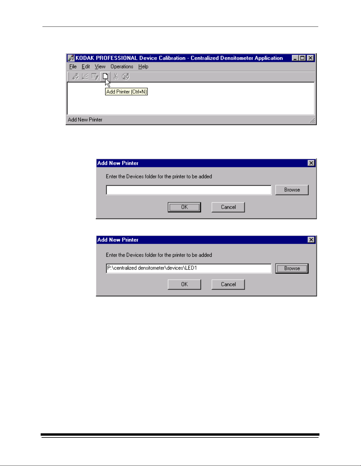
Installing and Using the Centralized Densitometer Application
Adding a Printer
1. Click the Add Printer icon or select File->New on the Centralized
Densitometer Application window.
The display shows the Add New Printer dialog box.
2. Either type a path or click Browse and select a path. Click OK.
4-6 March 2001
Page 75

Installing and Using the Centralized Densitometer Application
The display shows the Centralized Densitometer Application window with the
new printer added.
Deleting a Printer
1. Highlight the printer you want to delete.
2. Click the Delete icon or select Edit->Delete Printer on the Centralized
Densitometer Application window.
March 2001 4-7
Page 76

Installing and Using the Centralized Densitometer Application
The display shows the dialog box below.
3. Click Yes to delete the printer.
The selected printer is no longer visible in the Centralized Densitometer
Application window.
4-8 March 2001
Page 77

Installing and Using the Centralized Densitometer Application
Changing Printer Information
1. Highlight the printer for which you want to change the information (location).
2. Click the Printer Info icon or select Edit->Printer Info on the Centralized
Densitometer Application window.
The display shows the Update Printer Information dialog box.
3. Change the location for the printer as needed and click OK.
March 2001 4-9
Page 78
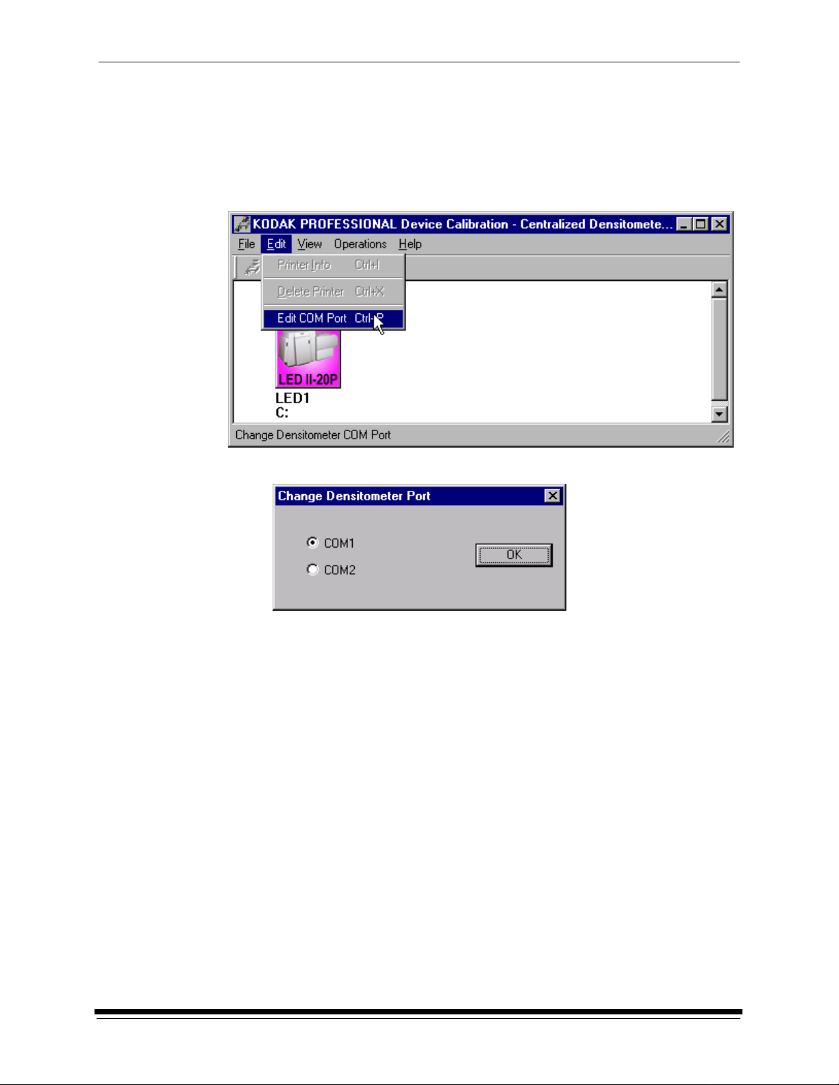
Installing and Using the Centralized Densitometer Application
Changing the Densitometer Port
You can change the designation of the port on your host computer to which the
densitometer is attached.
1. Select Edit->Edit COM Port on the Centralized Densitometer Application
window.
The display shows the Change Densitometer Port dialog box.
2. Click in the circle next to either COM1 or COM2 and click OK.
4-10 March 2001
Page 79

Installing and Using the Centralized Densitometer Application
If you change the port, a message is displayed on the status bar of the
Centralized Densitometer Application window.
March 2001 4-11
Page 80

Installing and Using the Centralized Densitometer Application
Measuring Densities During a Calibration Cycle
IMPORTANT: To use the centralized densitometer application for measuring
densities for a calibration cycle, the density source of “centralized
densitometer” must have been selected in the edit configuration
dialog for the device being calibrated; see “Editing Information on
the Density Source Tab” on page 3-28.
1. Open the Centralized Densitometer Application. The display shows the
window for the Centralized Densitometer Application.
2. Highlight the printer.
3. Click the Measure icon (or select Operations->Measure) to measure the
target images.
4. At the densitometer, measure the densities (see “Using the Densit ome ter to
Read Densities” on page 1-7).
When the densities are measured, the status bar on the Centralized
Densitometer Application window displays “Ready.”
The density measurements are automatically sent to the LED printer’s host
computer.
4-12 March 2001
Page 81

Installing and Using the Centralized Densitometer Application
Viewing Calibration Graphs
The View Graphs feature provides access to the available graphs from the most
recently completed calibration for th e selected printer .
For examples of the graphs, see “Viewing Graphs” beginning on page 3-13. The
Value and Difference Graphs reflect the densitometer values that were last read.
The History Graph displays the data from completed calibrations.
To view calibration graphs from the Centralized Densitometer application:
1. Highlight the printer you want to view graphs and click the Graphs icon or
select View->Graphs.
The display shows one of the graphs; typically it is the Value graph.
2. Select the Graph Type that you want to view. When the display shows the
graph, select the type of data and planes that you want to see.
NOTE: Y ou will get a message if there is no calibration data for the selected printer.
March 2001 4-13
Page 82

Installing and Using the Centralized Densitometer Application
4-14 March 2001
Page 83

Page 84

EASTMAN KODAK COMPANY
Rochester, New York 14653
U.S.A.
KODAK CANADA INC.
Toronto, Ontario M6M 1V3
Canada
Kodak and Kodak Professional are
trademarks of
Eastman Kodak Company
©Eastman Kodak Company, 2001 Printed in U.S.A.
 Loading...