

Knight Equipment RMP-300 Installation Manual
RMP-300 Digital
Instruction Manual
A101453 Rev: x1 (4/11) Page 1 of 24

TABLE OF CONTENTS
Specifications ....................................................................................................... 3
Unit and Remote Dimensions ............................................................................... 4
Package List ......................................................................................................... 5
Installation Diagram .............................................................................................. 6
Installation and Assembly
Mounting..................................................................................................... 7
Plumbing .................................................................................................. 8-9
Dry Detergent Plumbing .......................................................................... 10
Probe Installation ................................................................................. 10-11
Product Wiring ..................................................................................... 12-13
Operation ....................................................................................................... 14-16
Programming ................................................................................................. 17-22
Declaration of Conformity……………………………………………………………..23
Warranty ............................................................................................................. 24
SAFETY SYMBOL EXPLANATIONS
Listed below are explanations of the safety symbols that appear either on the unit, in the instruction manual, or both.
Please familiarize yourself with the meaning of each symbol.
GENERAL CAUTION: This symbol indicates a general safety caution.
Page 2 of 24 A101453 Rev: x1 (4/11)
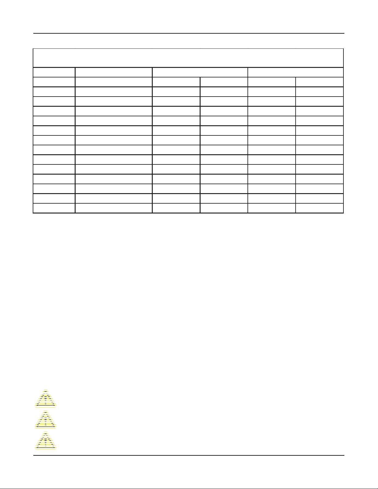
SETTING GUIDE
RMP VALUE RANGES
MODE DESCRIPTION
DetConcen Detergent Concent ration 0 - 100K 0 - 100K N/A N/A
AlarmDelay Alarm Delay 0 - 512s 0 - 512s N/A N/A
Rac k Ti me Rac k Time N/ A 0 - 30 s N/ A 0 - 3 0s
InitCharge Initial Charge N/A N/A 0 - 64s 0 - 128s
Recharge Recharge N/A N/A 0 - 20s 0 - 20s
RecAfRac ks Recharge After N Rack s N/A N/A 0-5 0-5
RinseDelay Rins e Delay 0 - 14s N/A 0 - 14s N/A
RinseLimit Rinse Limit 0 - 30s N/A 0 - 30s N/A
ResetRackCNT Reset Rack Count Y/N Y/N Y/N Y/N
ResetInitCNT Reset Initial Charge Count N/A N/A Y/N Y/N
InitChaRepeat Initial Charge Repeat N/A N/A Y/N Y/N
SanRunWith Sanitizer Run With Det/Rinse Det/Rinse Det/Rinse Det/Rinse
SanSpeed Sanitizer S peed 0 -100% 0 -100% 0 -100% 0 -100%
PROBE MODE PROBELESS MODE
DOOR CONVEYOR DOOR CONVEYOR
SPECIFICATIONS
Pollution degree ................................................................................................ 2
Installation category ......................................................................................... 2
Altitude .............................................................................. <2187 yard (<2000 m)
Humidity ......................................................................................... 50% to 80%
Electrical supply
Main supply voltage fluctuations are not to exceed 10 percent of the
nominal supply voltage Indoor use only
Replacement Fuse…………………….1Amp, 250V, 5x20mm, Fast-Acting
Ambient Temperature
Rinse flow rate ............................................... .1-1.5 oz/min (3-45 ml/min)
Detergent flow rate ................................................ 7.8 oz/min (230 ml/min)
Sanitizer flow rate .............................................. .2-3 oz/min (6-90 ml/min)
Main Unit Weight ........................................................................ 8 lb. (3 kg)
SAFETY PRECAUTIONS
CAUTION: Wear protective clothing and eyewear when dispensing chemicals or other
materials. Observe safety handling instructions (MSDS) of chemical mfrs.
........................................... 115, 208, or 230 Vac, 50/60 Hz
..................................... 41°F to 104°F (5°C to 40°C )
CAUTION: To avoid severe or fatal shock, always disconnect main power when
servicing the unit.
CAUTION: When installing any equipment, ensure that all national and local safety,
electrical, and plumbing codes are met.
A101453 Rev: x1 (4/11) Page 3 of 24
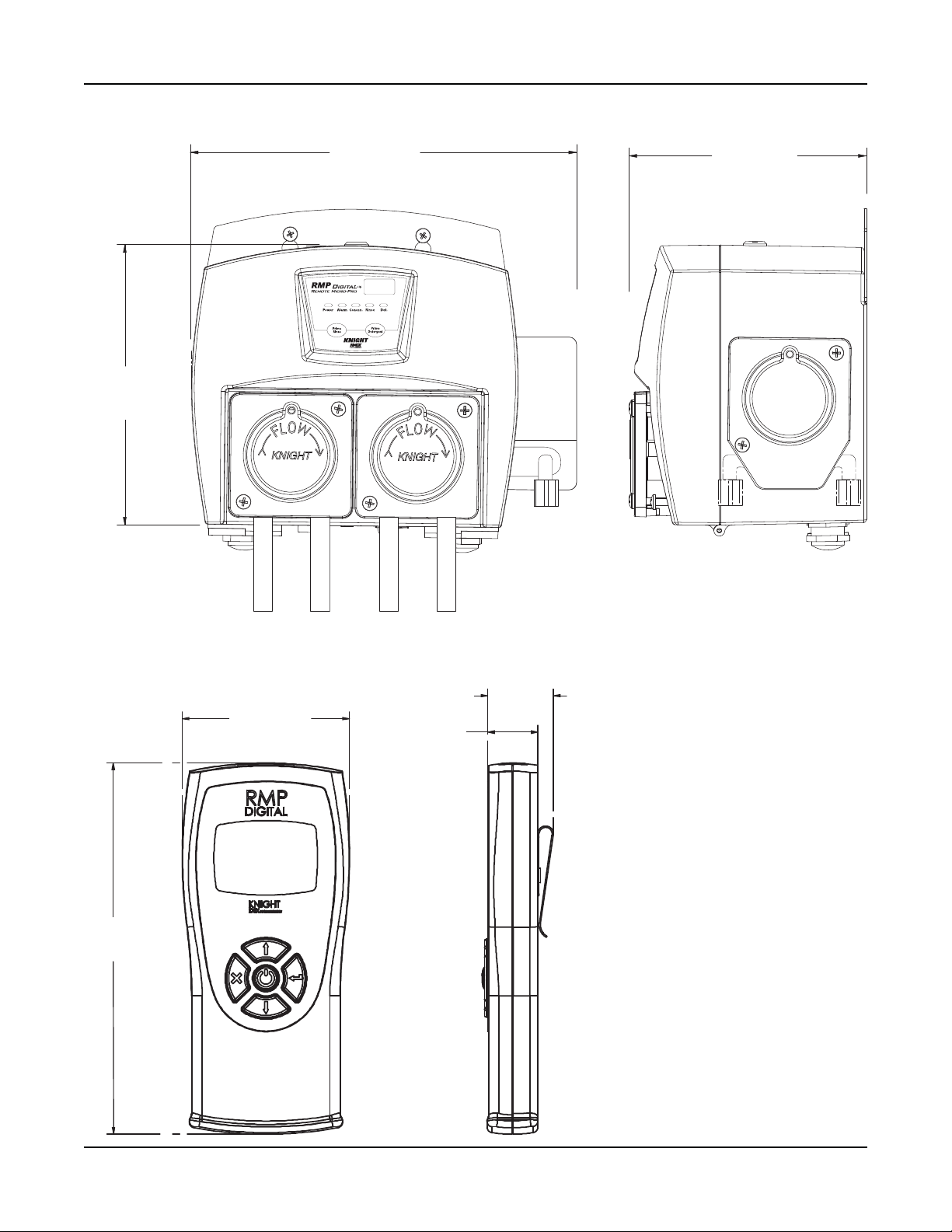
MAIN UNIT DIMENSIONS
”
7.088”
(180 mm)
9.75”
(248 mm)
6.041”
(153 mm)
REMOTE DIMENSIONS
2.528”
(64 mm)
5.620”
(143 mm)
.994
(25 mm)
.758”
(19 mm)
Page 4 of 24 A101453 Rev: x1 (4/11)
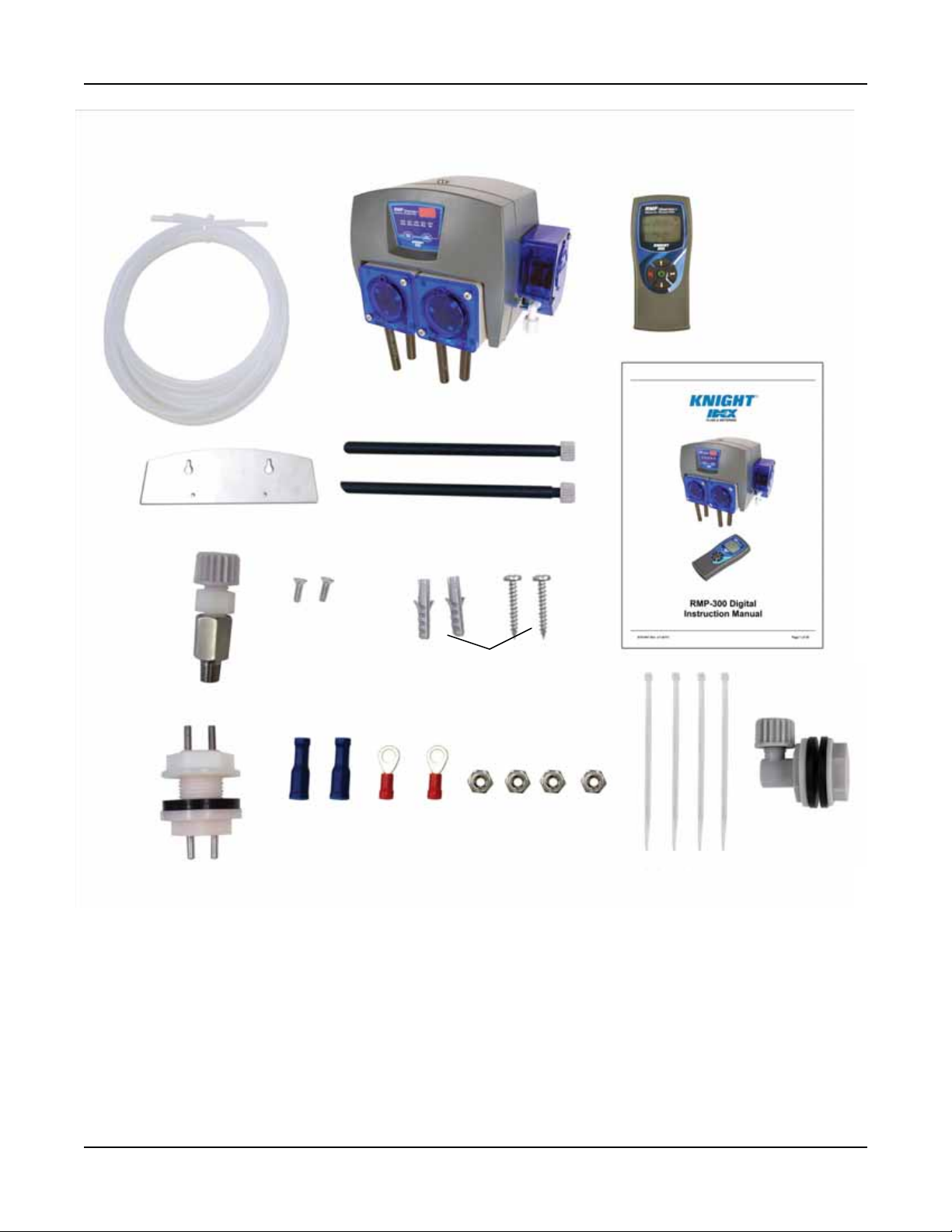
PACKAGE CHECKLIST
1
4
3
2
7
8
10 12 13 11
1. 1/4 “ Poly-tubing, 6 meters (7005190)
2. RMP-300D
3. RMP Remote (7150000)
Note: Not included in all RMP
4. Mounting Plate (A100609)
5. Pick-up tube (7020180)
6. Instruction Manual (A101453)
7. Check Valve, 1/4 tube (7901320)
8. 2 x Flat head rolling screw (S100076)
5
6
9
15
14
9. 2 x Expansion screw: includes wall anchor
and screw (7600121)
10. Probe: includes gasket & nut lock (7005190)
11. 2 x Bullet connector, blue (0300650)
12. 2 xTerminal ring tongue (2000682)
13. 4 x Nut, #8-32, hex, S.S. (1400438)
14. 4 x Tie wrap
15. Bulkhead fitting (7023342)
A101453 Rev: x1 (4/11) Page 5 of 24
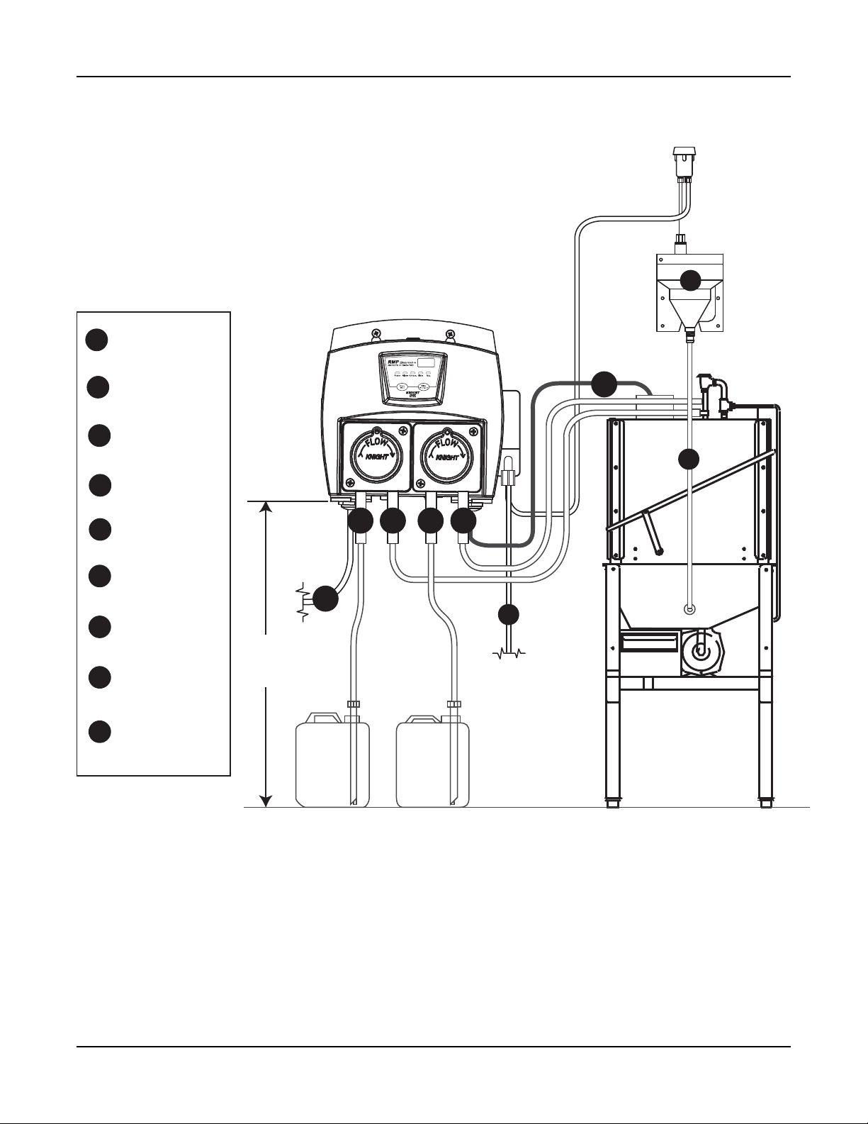
INSTALLATION DIAGRAM (RMP-300)
A
Rinse Suction
I
Rinse Discharge
B
Sanitizer Suction
C
Sanitizer
D
Discharge
E
Power
Rinse & Detergent
F
Signals
Water
G
Detergent
H
Discharge
Powder/Solid
I
type feeder
MAX
2 m
A B C D
E
Rinse
F
H
G
Sanitizer
Page 6 of 24 A101453 Rev: x1 (4/11)
INSTALLATION & ASSEMBLY
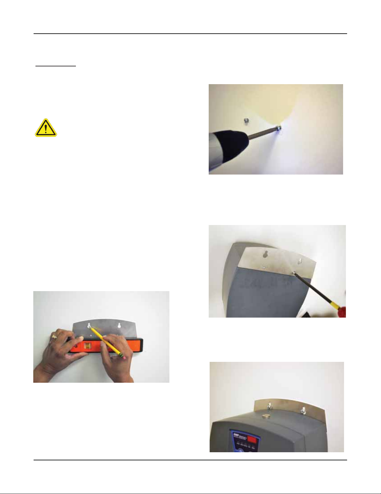
MOUNTING
Mount the unit on a nearby wall (using suitable
hardware) or on top of the dishwasher if desired.
Try to keep the unit within three feet from the
final rinse line to avoid long tubing runs.
CAUTION: Do not mount the unit in the
direct path of steam. This can short
circuit and permanently damage the
unit. Mounting the unit on the side, on
the back, or on the vents of the
dishwasher may cause thermal
overload and damage or hinder the
performance of the unit.
Check all applicable plumbing and
electrical codes before proceeding with
the installation. This will help to ensure
that the system is installed in safe and
suitable manner. A wiring schematic of
the dishwasher should be used as
reference for making electrical
connections — this is typically provided
by the dishwasher manufacturer if one
cannot be located on the machine itself.
Step 2: Pre-drill pilot holes at the marked
location. Insert wall anchor into the wall. Screw
expansion screw (10) into wall anchor in wall.
Step 3: Install mounting bracket on back of
RMP dispenser (2) using flat head rolling screw
(8).
Step 1: Use level to mark hole location for
mounting bracket (4)
Step 4: Hang unit on two screws installed in
step 2
A101453 Rev: x1 (4/11) Page 7 of 24
INSTALLATION & ASSEMBLY
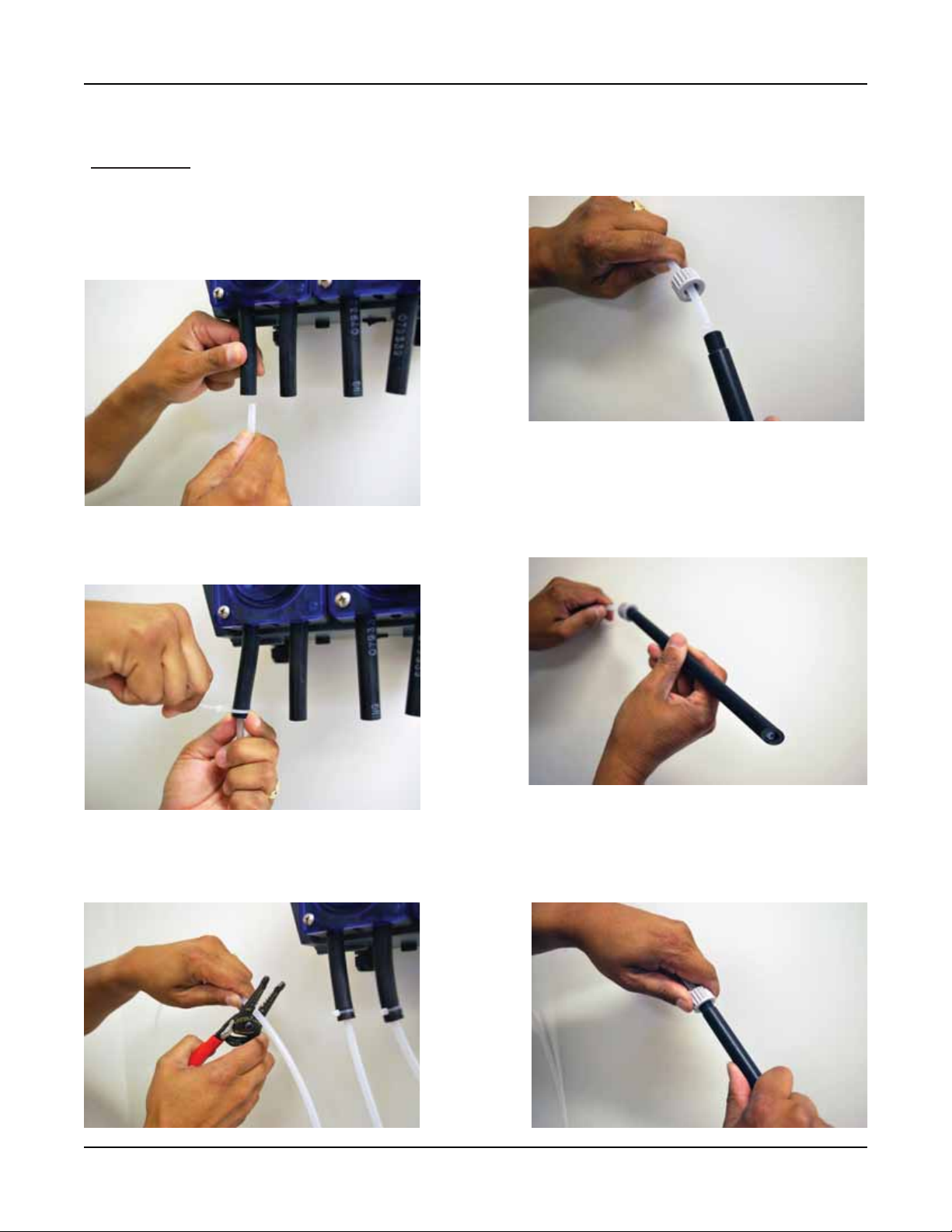
PLUMBING
LIQUID RINSE & SANITIZER PLUMBING
Step 1: Insert 1/4" OD poly tube (1) in suction
(left) side of the peristaltic pump.
Step 2: Secure with tie wrap (14)
Step 4: Insert suction end of 1/4" OD poly tube
into pick-up tube (5)
Step 5: Insert poly-tube to the end of 1/4" OD
poly tube leaving 5 mm from the end of the tube.
Step 3: Cut 1/4" OD poly tube to the appropriate length from pump to chemical container
Page 8 of 24 A101453 Rev: x1 (4/11)
Step 6: Tighten grey compression nut on top of
pick-up tube to secure poly-tube in place.
 Loading...