

Knight Equipment PRO-WATCH 510TMS Installation Manual

352:$7&+0,67,1*6<67(0
,16758&7,210$18$/
INTRODUCTION
If you received this manual as part of the Misting Kit, please see page 5. For all other applications, continue on...
The Pro-Watch Misting System is a liquid dispenser designed to automatically spray predetermined volumes of
chemicals such as deodorants and odor suppressants into trash compactors, trash bins, or any other application
requiring chemical treatment. The microprocessor timer activates the peristaltic pump which pushes liquid through a
spray nozzle, permitting large areas of waste to be treated.
The Pro-Watch uses an MT-300 control, capable of up to 20 separate run events per day. Each event can run for up
to 16 minutes. The MT-300 also has a security feature to prevent accidental or unauthorized programming changes,
and an “onboard” battery (with 5-year life) keeps the current time setting in the event of main power loss. All
programmed information is saved in non-volatile memory.
INSTALLATION
APPLICATION NOTE: Do not use system in freezing temperatures.
(1) Mount the unit on a wall using the supplied mounting bracket (customer must supply hardware to install).
Choose a mounting location near both the injection point and chemical supply. CAUTION: Do not mount the unit
in the direct path of steam. This can short circuit and permanently damage your system.
(2) If applicable, connect main power wires as shown in the wiring diagram on page 3, and per local electrical
codes. Failure to do so will void warranty.
(3) Mount the spray nozzle assembly (horizontal or vertical) in the desired location. Do not
protective cap from the nozzle while mounting — it prevents damage to the spray tip from tools or handling.
(4) Install poly tubing between the pickup tube and the input (left) side of the pump’s squeeze tube. Use a hose
clamp to secure poly tubing to the squeeze tube. Be sure to draw poly tubing through the end of the pickup tube.
(5) Insert the footvalve (strainer) into the bottom of the poly tube.
(6) Install poly tubing between the output (right) side of the pump’s squeeze tube and the elbow fitting on the spray
nozzle assembly. Push the poly tubing into the elbow fitting to secure it. Use a hose clamp to secure poly tubing
to the squeeze tube.
(7) Remove the green protective cap mentioned in step 3.
(8) To prime the pump, insert the pickup tube into the chemical container and press the “PRIME 1” button on the
front cover of the system. The pump will run as long as the button is pressed.
remove the green
HOW TO EASILY CALCULATE PUMP RUN TIMES
The pump dispenses about 3 ounces per minute under normal operation with the nozzle in place. The actual flow
rate of the pump will vary depending on product viscosity, tubing distance, and other factors. The steps below will
help you in determining the run time required to dispense the volume needed for your application.
(1) Make sure the chemical lines (both the pickup side and output side of the pump) are fully primed.
(2) Place a beaker or measuring cup under the spray nozzle, then hold down the PRIME 1 button for 30 seconds.
(3) Check the volume dispensed into your container and multiply by 2 — this will determine the actual flow rate of
the pump in oz/minute.
(4) Use this flow rate to determine how long you will need the pump to run to delivery the dosage required for your
application.
0900905 Rev: F (03/02) Page 1 of 8

OPERATION NOTES
During normal operation, the clock will display briefly when a run event starts, or while PRIME button is pressed.
•
During programming, if a button is not pushed within 2 minutes, the display will disappear and the control will
•
return to normal operation.
BUTTON FUNCTIONS
PRGM: Steps you through the setup program.
PRIME 1 (Ø): Manually activates the pump and shows clock when not programming.
Advances numbers downward when programming.
PRIME 2 (×): Manually activates the solenoid (if applicable) and shows clock when not programming.
Advances numbers upward when programming.
SECURITY FEATURE — REMOVE JUMPER JP1 TO PROGRAM
To prevent unauthorized tampering, the events and time/day setting can be “secured” by placing a jumper on the
JP1 pins on the back of the MT-300 circuit board. The jumper acts like a lock and key...when the MT-300 is secured
(jumper on) the display will show “SECU” if the PRGM button is pressed. The PRIME buttons are not affected and
will still function in their normal manner. Removing the jumper allows the MT-300 to be programmed or to change the
time of day clock. Replace jumper when done programming if you wish to secure the system.
HOW TO SET THE SYSTEM
(1) Press the PRGM button.....set the clock to the current time of day. Use ×/Ø to set the clock (note AM/PM).
(2) Press PRGM again.....PE 1 will be displayed. PE stands for P
to set the number of pump events per day that are required. The system will activate only the number of pump
events indicated by the PE #.
(3) Press PRGM again.....E 1 will be displayed indicating that you are going to program the first event.
(4) Press PRGM again.....pump start time will be displayed. Use ×/Ø to set pump start time (note AM/PM).
(5) Press PRGM again.....pump run time will be displayed. Use ×/Ø to set the pump run time (min:sec).
(6) Press PRGM again.....E 2 will be displayed if you selected more than 1 pump event (PE) per day. Repeat the
event programming instructions above to program all pump events. After all pump events are programmed, you
will return to the blank display.
(7) To review your programming, press the PRGM button and slowly step through the program. Make changes as
necessary referring to the above instructions.
If you hold down any of the buttons while programming, the numbers will scroll much faster.
Tip:
If you get lost in the program, press PRGM until you return to blank display. Then repeat instructions above.
Tip:
ump Events (“on” times) needed per day. Use ×/Ø
Page 2 of 8 0900905 Rev: F (03/02)
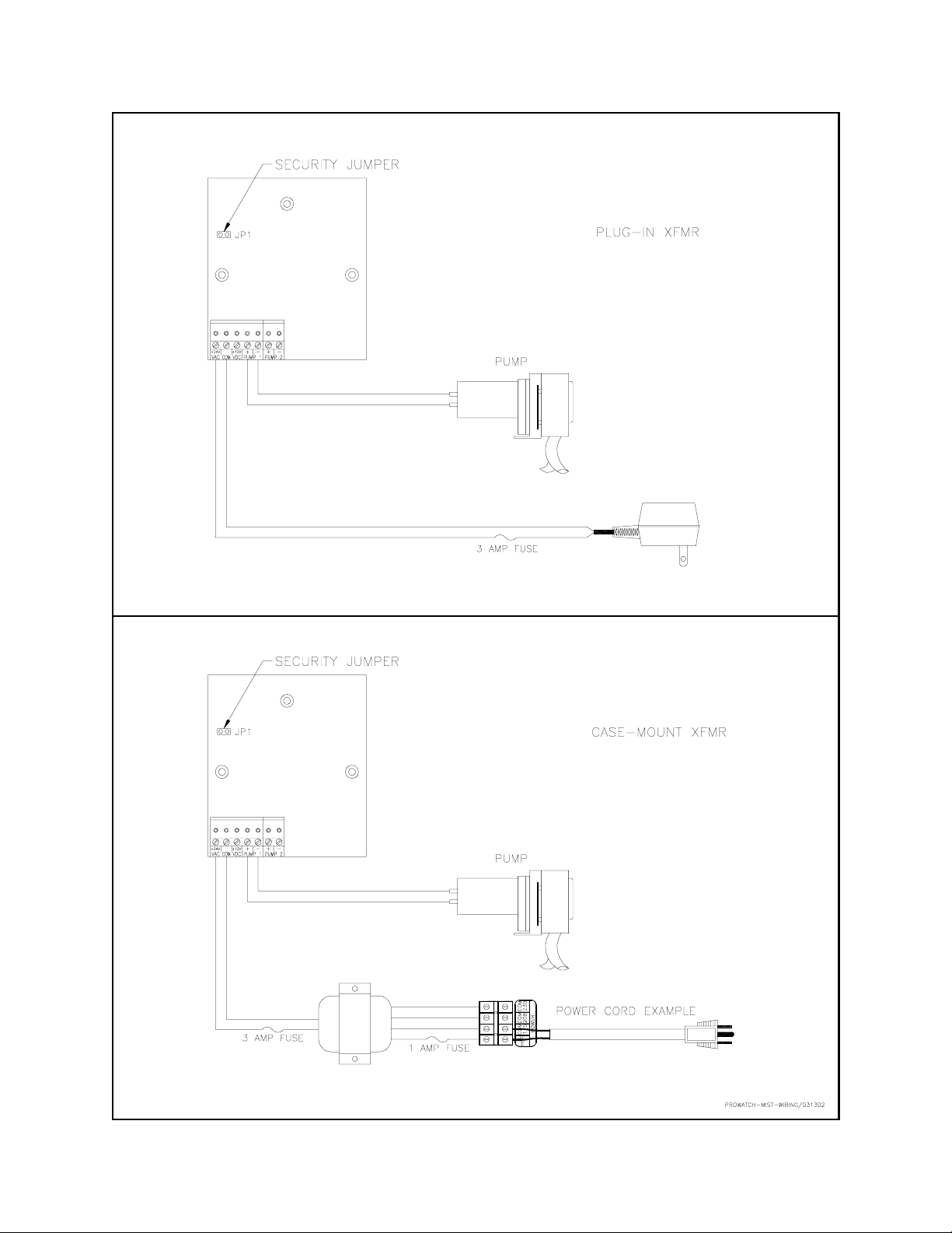
WIRING DIAGRAM
0900905 Rev: F (03/02) Page 3 of 8
 Loading...