

Page 1

Klark Teknik Group,
Klark Teknik Building,
Walter Nash Road,
Kidderminster.
Worcestershire.
DY11 7HJ.
England.
Tel:+44 1562 741515
Fax:+44 1562 745371
Email: sales@ktgplc.com
Website: www.klarkteknik.com
OPERATORS MANUAL
DN9340 Software V2.05
DN9344 Software V2.02
HELIX SYSTEM
DN9340 / DN9344
Page 2

Page 3
IMPORTANT SAFETY INSTRUCTIONS
These symbols are internationally accepted symbols that warn of potential hazards with
electrical products.
The lightning flash with arrowhead symbol, within an equilateral
triangle is intended to alert the user to the presence of uninsulated
“dangerous voltage” within the product's enclosure that may be of
sufficient magnitude to constitute a risk of electric shock to persons.
The exclamation point within an equilateraltriangle is intended to alert
the user to the presence of important operating and maintenance
(servicing) instructions in the literature accompanying the appliance.
1. Read these instructions.
2. Keep these instructions.
3. Heed all warnings.
4. Follow all instructions.
5. Do not use this apparatus near water.
6. Clean only with a dry cloth.
7. Do not block any of the ventilation openings. Install in accordance with the manufacturers
instructions.
8. Do not install near any heat sources such as radiators, heat registers, stoves, or other apparatus that
produce heat.
9. Do not defeat the safety purpose of the polarized or grounding-type plug. A polarized plug has two
blades with one wider than the other. A grounding type plug has two blades and a third grounding
prong. The wide blade or third prong are provided for your safety. When the provided plug does not fit into
your outlet, consult an electrician for replacement of the obsolete outlet.
10. Protect the power cord from being walked on or pinched particularly at plugs, convenience
receptacles, and the point where they exit from the apparatus.
11. Unplug this apparatus during lightning storms or when unused for long periods of time.
12. Refer all testing to qualified personnel. Servicing is required when the apparatusisdamagedinany way,
such as power-supply cord or plug is damaged, liquid has been spilled or objects have fallen into the
apparatus, the apparatus has been exposed to rain or moisture, does not operate normally,orhasbeendropped.
CAUTION
RISK OF ELECTRIC SHOCK
DO NOT OPEN
WARNING:
TO REDUCE THE RISK OF FIRE OR ELECTRIC SHOCK,
DO NOT EXPOSE THIS APPLIANCE TO RAIN OR MOISTURE
AVIS:
RISQUÉ DE CHOC ELETRIQUE. NE PAS OUVRIR
Page 4

Page 5
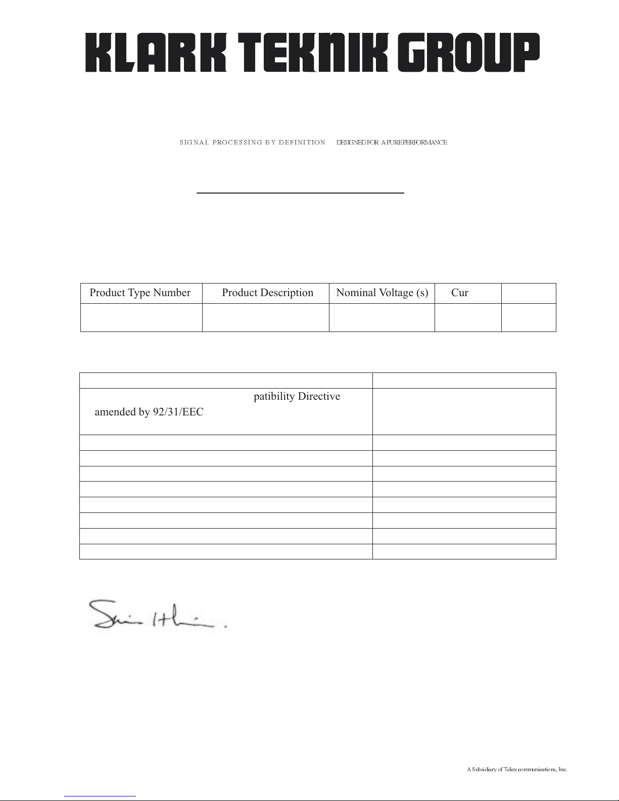
DECLARATION OF CONFORMITY
We,
of, Klark Teknik Building, Walter Nash Road, Kidderminster, Worcestershire, DY11 7HJ
Declare that a sample of the following product:-
to which this declaration refers, is in conformity with the following directives and/or standards:-
Signed:............................
Name: Simon Harrison
Authority: R&D Director, Klark Teknik Group (UK) PLC
Attention!
Where applicable, the attention of the specifier, purchaser, installer or user is drawn to special limitations of use
which must be observed when these products are taken into service to maintain compliance with the above
directives. Details of these special measures and limitations to use are available on request and are available
in product manuals.
Klark Teknik Group (UK) PLC
Walter Nash Road, Kidderminster, Worcestershire. DY11 7HJ. England
Tel: +44 1562 741515. Fax: +44 1562 745371
Company Registration No: 2414018
abc abc
SIGNAL PROCESSING BY DEFINITION DESIGNEDFOR APUREPERFORMANCE
Product Type Number Product Description Nominal Voltage (s) Current Freq
DN9340 Digital Equaliser 115V AC 200mA
100mA
50/60Hz
DN9344 230V AC
Date: 24th April 2003
A Subsidiary of Telex communications, Inc.
Directive(s) Test Standard(s)
89/336/EEC Electromagnetic Compatibility Directive
amended by 92/31/EEC & 93/68/EEC 73/23/EEC,
Low Voltage Directive, amended by 93/68/EEC
Generic Standard Using EN50130 Limits and Methods EN50081/1
Class B Conducted Emissions
Class B Radiated Emissions
Fast Transient Bursts at 2kV EN61000-4-4
Static Discharge at 4kV EN61000-4-2
Electrical Stress Test EN60204
Electrical Safety UL6500-99
E60065-00
EN50130
EN50130
Page 6

Page 7

l abc
Thank you for using a Klark Teknik product
After you have unpacked
Quick reference
Introduction and key features
Identification of controls: DN9340
Connections: DN9340
Signal flow: DN9340
Operation: DN9340
Remote Control
Identification of controls: DN9344
Signal flow: DN9344
Operation: DN9344
Application notes:
Technical specifications: DN9340
Technical specifications: DN9344
Service Information
1
3
5
7
9
13
15
Home page 17
Graphic equalisation 19
Parametric equalisation 22
Dynamic equalisation 24
Filters 26
Storing and recalling settings 28
Setup menu 29
Metering 30
Clear down sequence 31
32
37
41
Remote Control Mode 42
Contact Closure (RELAY) Mode 43
Stand Alone Mode 44
Application note 1: dynamic EQ 45
Application note 2: What do we mean by all these Q types? 48
51
52
53
Contents
T-DEQ
T-DEQ
Page 8

l abc
Page 9

.
1
l abc
Thank you for selecting the Klark Teknik Helix System digital equaliser. The equaliser continues the Klark
Teknik tradition of providing superb audio performance, technical accuracy and rugged reliability. At the
same time it offers unprecedented levels of flexibility by incorporating graphic, parametric and dualthreshold dynamic equalisation ( ) in a single unit. In view of this flexibility we hope that you will
spend a little time to read this manual, as this will allow you to obtain the very best results with minimum
effort. We also drawyou attention tothe “Important safetyinformation” page at the beginningof the manual.
For those of you in a hurry,the quick reference guides are on pages 5 and 6.
Do not install this unit in a location subjected to excessive heat,dust or mechanical vibration.
Connection is made by means ofan IEC standard powersocket. The rear panel text indicatesthe voltage range
required for satisfactory operation of the unit.
Before connecting this unit to the mains supply, ensure the fuse fitted is the correct type and rating is as
indicated on the rear panel, adjacent to the fuse holder.
This unit is fitted with a standard fused IEC mains inlet: For safety reasons the earth lead should never be
disconnected.
To prevent shock or fire hazard, do not expose the unit to rain or moisture. To avoid electrical shock do not
remove covers. Refer servicing to qualified personnel only.
This product should only be used with high quality, screened twisted pair audio cables, terminated with metal
bodied 3-pin XLR connectors. Any other cable type or configuration for the audio signals may result in
degraded performance due to electromagnetic interference.
Should this product be used in an electromagnetic field that is amplitude modulated by an audio frequency
signal (20Hz to 20kHz), the signal to noise ratio may be degraded. Degradation of up to 60dB at a frequency
corresponding to the modulation signal may be experienced under extreme conditions (3V/m, 90%
modulation).
Precautions
Voltage Selection and Power Connection
Safety Warning
Attention! Cables
Electric Fields:
The Klark Teknik Helix System
T-DEQ
Page 10

2
l abc
Page 11

3
l abc
After You Have Unpacked The Unit
Save all the packing materials - they will prove valuable should it become necessary to transport or ship this
product.
Please inspect this unit carefully for any signs of damage incurred during transportation. It has undergone
stringent quality control inspectionand everypossible effort has beenmade toensure that it left the factoryin
perfect condition.
If, however, the unit shows any signs of damage, please notify the transportation company without delay.
Only you, the consignee, may institute a claim against the carrier for damage during transportation.
If necessary, contact your supplier or as a last resort, your Klark Teknik importing agent, who will fully cooperate under such circumstances.
This
Side Up
KIDDERMINSTER ENGLAND
Page 12

4
l abc
Page 13
5
l abc
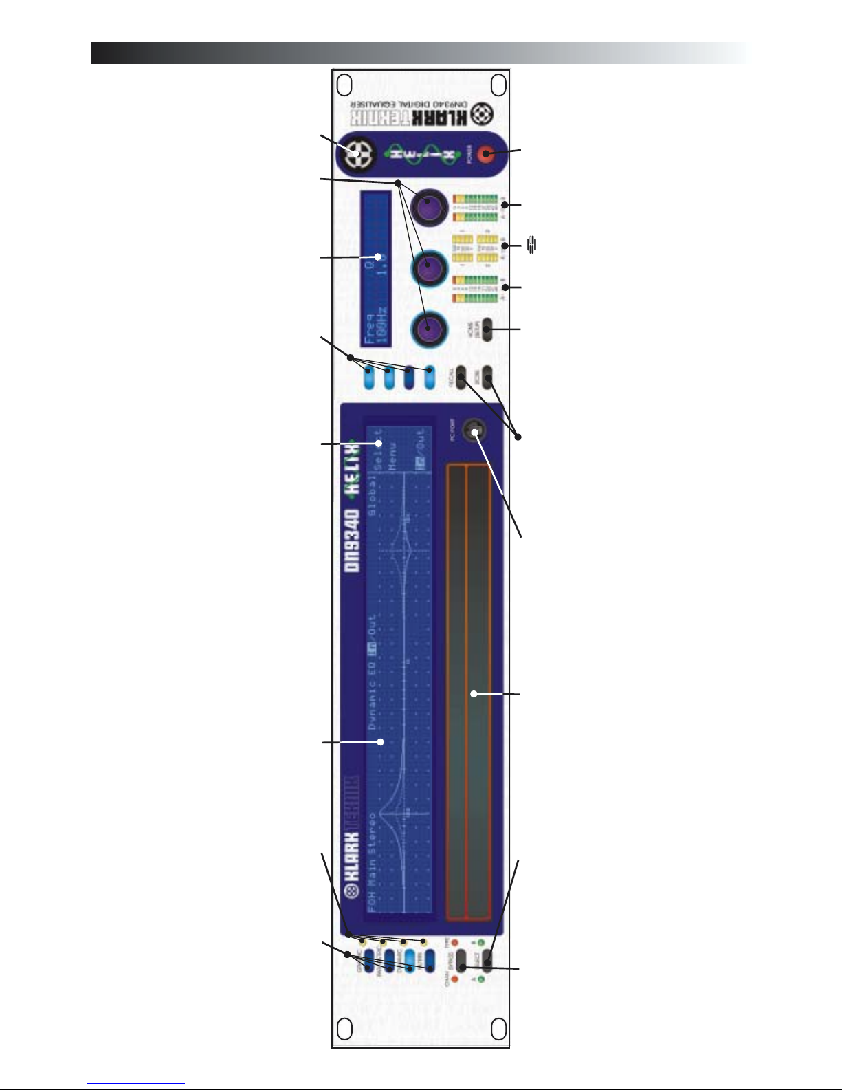
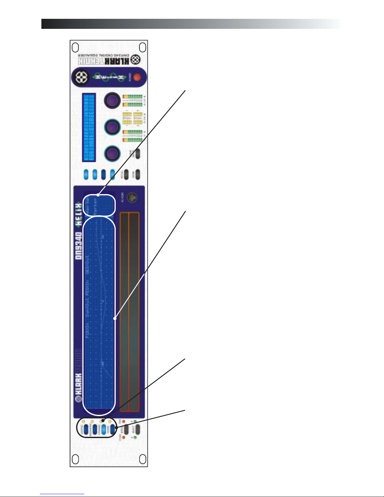
Quick reference: DN9340
Access keys to control each type of
equalisation - press HOME(SETUP) key to
return to thehome page.
EQ active lights - these show if a particular
type of EQ is currently affecting the overall
frequency response.
Main graphic display - this shows the
frequency response of the selected type of
EQ, or theoverall response onthe home page.
This area of the main graphic display labels
the soft key functions. Typically these
include “select” to choose a particular filter,
and “menu”to step round a circular choice of
options for that type of EQ. On the home
page these buttons access the gain, delay,
naming functions.
Soft keys for selecting options and secondary
functions.
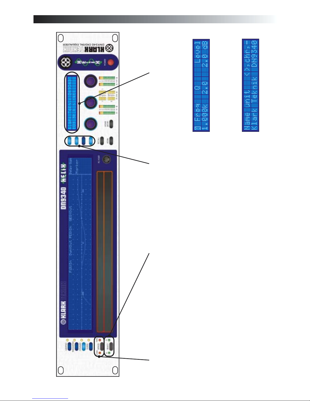
Alphanumeric display - this showsparameter
values for the current function being
controlled by theencoder knobs.
Power ON indication.
Power switch.
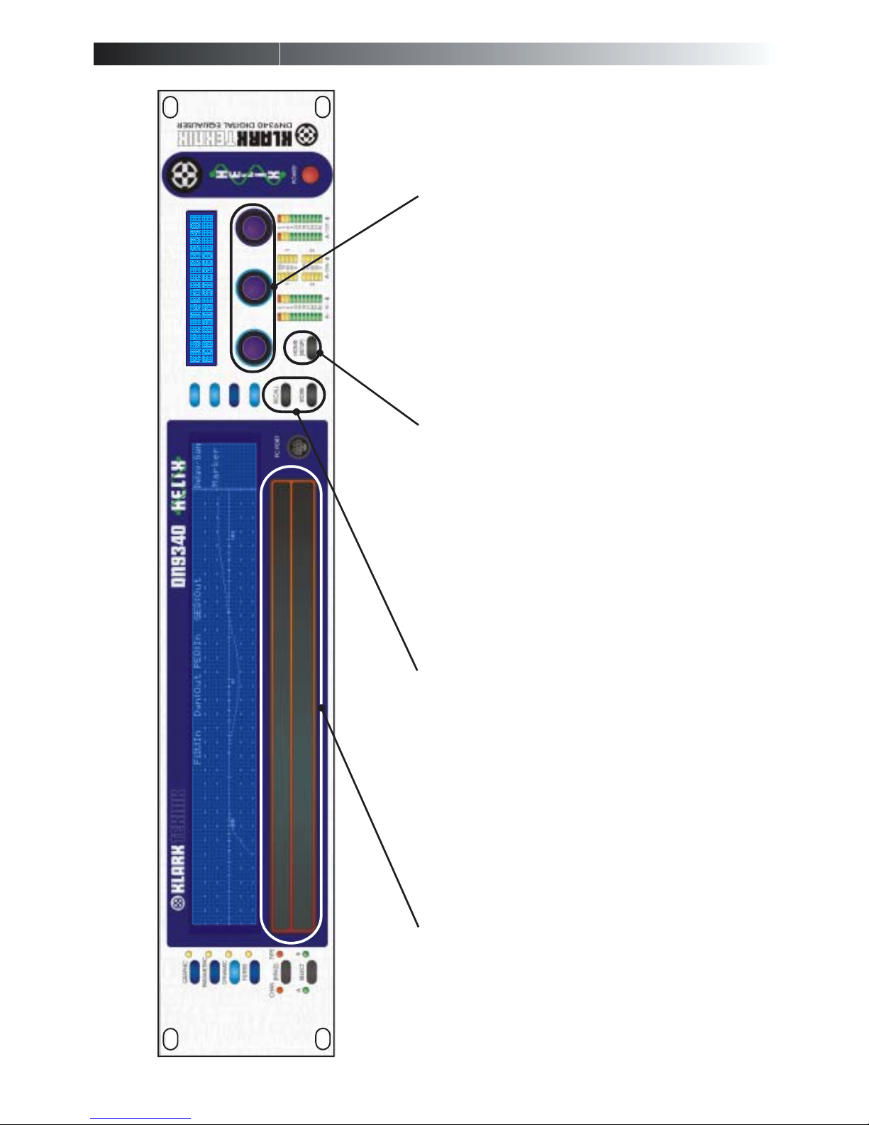
The left, centre and right encoder knobs used for controlling values and selecting
options.
Input metering incorporating multi-point clip
indication.
dynamic EQ metering.
Output metering incorporating multi-point
clip indication.
HOME(SETUP) key. Press once to return to
the home page. Onceon the homepage, press
and hold for one second to access the Setup
menu. Step through the Setup menu (and exit
after the last item) by repeatedly pressing this
key.
STORE and RECALL keys. Used to store
complete unit settings to one of the 64
memory locations andthen to recallthem.
PC port connector. Use with the supplied
cable to install software updates or to control
the unit froman external computer.
Two part touchstrip. Press either part briefly
to select a particular filter or fader. In
Graphic EQ mode, press and hold to increase
the level (upper strip) or reduce it (lower
strip).
Channel select key. Press to select either
channelAor B for control. If the unit is linked
for stereo operation then both indicators will
be lit.
Bypass key - on the home page this bypasses
the complete unit for the selected channel
(both channels if linked). When a particular
EQ type is selected (by the keys above the
bypass switch), the bypass operates on that
type of EQonly.
If you have received the unit in an unknown
state, and wish to clear it down to ensure
that no EQ is active, please refer to the
information onpage 29.
T-DEQ
Page 14
6
l abc
Power switch.
Power on indicator.
Section 1 output metering incorporating multi-point
clip indication.
Section 1 dynamic EQ metering.
Section 1 input metering incorporating multi-point
clip indication.
Section 2 output metering incorporating multi-point
clip indication.
Section 2 dynamic EQ metering.
Section 2 input metering incorporating multi-point
clip indication.
SETUP key. Press and hold to enter SETUP menu. A
momentary press toggles between the electronic
scribble-strip displays and display of Last Memory
Recalled and Communications Mode.
Communications Mode isnot editable when display is
accessed this way.
The large red alphanumeric displays can be used to
show electronic scribble-strip information, Last
Memory Recalled, andCommunications Mode.
Display mode indicator (blue) forSection 1. When lit
this indicates that the large red displays are now
showing Last Memory Recalled and
Communications Mode. When not lit, the displays
are showing electronic scribble-strip names. In this
case the left-hand three characters show the name of
Channel A and the right-hand three the name of
Channel B.
Display mode indicator (blue) for Section 2. When lit
this indicates that the large red displays are now
showing Last Memory Recalled and
Communications Mode. When not lit, the displays
are showing electronic scribble-strip names. In this
case the left-hand three characters show the name of
Channel A and the right-hand three the name of
Channel B.
T-DEQ
T-DEQ
Remote ControlActive indicator (green) for Channel
1A. This shows that that the master unit is currently
controlling this channel by remote control. Often
referred to asthe “me” light.(repeat for 1B/2A/2B).
UP and DOWN keys for Section 1. Used to select
communications channel (address) for remote
control and also contact closure mode. Active only
when in SETUPmenu.
UP and DOWN keys for Section 2. Used to select
communications channel (address) for remote control
and also contact closure mode. Active only when in
SETUPmenu.
PC port connector. Use with the supplied cable to
install software updates or to control the unit from an
external computer.
Communications traffic indicators. These indicate
when there is activity on any of the external
interfaces. Transmit and receive data are shown for
front panel (RS-232) and rear panel (RS-485) data,
and also thecontact closure (RELAY) input.
Scribble-strip areas to allow easy labelling of the unit.
Use only chinagraph pencils to avoid permanently
marking the unit. Remove chinagraph markings by
wiping with a soft cloth. Do not use solvents as these
may damage thesurface.
Quick reference: DN9344
Page 15

7
The Klark Teknik DN9340 Helix equaliser is a two-channel audio equaliser packaged in a 2RU, 19” rackmounting format. The two channels can be controlled independently as two separate mono equalisers or
linked for stereo operation. The unit has been designed to build on Klark Teknik's unrivalled reputation for
high quality equalisation whilst addressing a number of limitations in more conventional products.
The Klark Teknik DN9344 Helix Slave equaliser is a 1U slave version of the DN9340 unit. By packaging
FOUR channels of Helix processing into a 1U case it offers unrivalled space efficiency, with a cost per
channel lower than many less flexible products. The DN9344 can be controlled from a master DN9340 unit
or by an external computer,and also has provision for contact closure operation.
In addition to the obvious
advantages of a dual-purpose unit, this allows the engineer to separate out different sections of
equalisation. For example, during setup and any soundcheck, the parametric mode can be used to set
a basic EQ for the venue, with maximum flexibility. Once the show starts, however, the engineer can
flip to graphic mode, whichnow starts off from a `flat'baseline. Any problems thatneed fast attention
during the show can now be addressed using the speed of operation of graphic EQ, and without
confusion between the `showtime' EQ and the original venue setup. At any time, a quick look at the
home page will show the true overall response of the unit.
Over the years a number of dynamic EQ products
have been introduced. These typically resemble a combination of a dynamics processor and an
equaliser. This approach has the disadvantage that whilst it is usually fairly easy to determine the
level at which the dynamic EQ willstart to operate, itis much harder tovisualise the likely effect as the
system is pushed harder or to set a maximum amount of EQ. The unique system developed by
Klark Teknik with its dual thresholds provides unrivalled clarity of operation making this a very
practical tool.
Since the advent of digital signal processors, it has been possible to pack ever
more functions into smaller boxes. However, if afunction is buried in a hard-to-find sub-menu which
is only accessible after navigating a complex series of button presses, it may as well not be included.
In live production theoperation ofthe unitis ascrucial asthe soundquality, and this is a key part of the
Helix design. The 2RU format permits a large graphic LCD display, and a second alphanumeric
display provides clear value readouts above the control knobs without using up space on the main
LCD. Dedicated selection buttons for the main functions, clear LED indicators, and no less that 8
separate bargraph meters ensure that the unit is fast and accuratein operation. The unique two-section
touchstrip provides instant access to filters andfaders, so that Helixprovides the same feeling ofbeing
“in control” familiar to users of Klark Teknik analogue graphicequalisers.
The Helix system allows exceptionally compact EQ systems to be assembled. For
example, one DN9340 and six DN9344 units would provide 26 channels of EQ, each with graphic,
parametric, and dynamic EQ, plus flexible filters, all in 8U of rackspace.
To further enhance the speed of operation of the Helix system, an
interface is provided which connects to Midas Heritage and Legend series consoles. This allows
the EQ system to be controlled automatically from the solo system of the console, ensuring that
the correct EQ device is always ready for instant access.
·
·
·
Simultaneous availability of graphic and parametric equalisation.
Threshold Dependent Dynamic EQ ( ).
Speed of operation.
Space efficiency.
Interface to Midas consoles.
l abc
Introduction and key features
T-DEQ
T-DEQ
·
·
Page 16

l abc
8
Page 17
l abc
9
Access keys to control each type of
equalisation; graphic, parametric,
dynamic and filters. Pressing one of
these keys selects the type of EQ to be
controlled. These keys do not affect the
actual sound at all - they just activate the
controls. The large display will change to
show the display for the selected EQ type,
and the “type” bypass LED will indicate
whether this section is bypassed or not.
The keys illuminate to show which type
of EQ is currently being controlled. Press
the HOME(SETUP) key to return to the
home page, which will show the overall
system response.
EQ active lights - these show if a
particular type of EQ is currently
affecting the overall response. Note that
this is not just an indication of the bypass
state. For example, if all the faders on the
graphic EQ are flat, then the light will not
be lit. If the graphic is not bypassed, and
then a fader is moved away from zero, the
light will now light to indicate that the
response is now being affected by the
graphic. This is particularly useful on the
home page where it can be quickly seen
what is contributing to the overall
Main graphic display - this shows the
frequency response of the selected type of
EQ, or the overall response on the home
page. Along the top edge is the name of
the current working memory, the in/out
status (bypass) of each type of EQ and the
unit name.
This area of the main graphic display
labels the soft key functions. Typically
these include “select” to choose a
particular filter, and “menu” to step round
a circularchoice of options for that type of
EQ. Additional functions include adding
new filters (parametric and filter modes
only) and selecting an individual fader or
filter to be in or out. On the home page
these buttons access the gain, delay,
naming and markerfunctions.
Identification of controls:DN9340
Page 18
l abc
Identification of controls:DN9340
10
Soft keys for selecting options and
secondary functions. These keys
illuminate to indicate whether they are
active in aparticular mode ornot.
Alphanumeric display - this shows
parameter values for the current function
being controlled by the encoder knobs. In
general, when setting parameters the
labelling is directly above the relevant
knob, with the title on the top row and the
value on thebottom row.
When selecting options or entering text,
the top row shows the title and the knob
functions separated by commas, with the
status on thebottom row.
Channel select key. Press to select either
channel A or B for control. If the unit is
linked for stereo operation then both
indicators will be lit and the key will be
inoperative.
Bypass key - on the home page this
bypasses the complete unit for the
selected channel (both channels if linked).
When a particular EQ type is selected (by
the keys above the bypass switch), the
bypass operates onthat type ofEQ only.
Page 19
11
The left, centre and right encoder knobs -
used for controlling values and selecting
options. Each knob is surrounded by an
illuminated blue ring which lights to show
that the knobis active inthe current mode.
HOME(SETUP) key. Press once to return
to the home page from any of the
individual EQ pages. Once on the home
page, press and hold for one second to
access the setup menu. Step through the
setup menu (and exit after the last item) by
repeatedly pressing this key. The
HOME(SETUP) key is also used to abort
from STORE andRECALLoperations.
STORE and RECALLkeys. Used to store
complete unit settings to one of the 64 user
memory locations and then to recall them.
In addition to user memories settings may
be recalled from “preset” memories that
can only be manipulated by means of an
external computer.
Two part touchstrip. The touchstrip is
used to select individual faders or filters
and can also be used to adjust gain
settings. Press either part briefly to select
a particular filter or fader. Press and hold
or tap repeatedly to increase the level
(upper strip) or reduce it (lower strip).
Note that the lower strip is wider than the
upper one to reflect that it is generally
more urgent to reduce gain... Pressing
upper and lower strips simultaneously
allows thecreation of fader groups.
l abc
Identification of controls:DN9340
Page 20

12
Input metering incorporating multi-point
clip indication. This meter indicates the
input level immediately after the input
gain trim.
dynamic EQ metering. Four
meters are provided to monitor all four
dynamic EQ filters.
Output metering incorporating multi-
point clip indication. These meters
indicate the actual level leaving the unit,
while the red clip light indicates internal
clipping (monitored throughout the
internal processing stages) irrespective of
actual output level
.
PC port connector, using a three-wire RS-
232 interface on a Mini-DIN connector.
Use with the supplied cable to install
software updates or to control the unit
from an external computer. Note that this
is entirely separate from the rear-panel
RS-232 and RS-485 connectors, and can
be used at the same time as the rear panel
connectors.
Power ON indication.
Power switch.
l abc
Identification of controls:DN9340
T-DEQ
Page 21

13
l abc
Connections:DN9340
RS-485 serial communications.
These connectors are connected in“loop
through” fashion, so either may be used
for input or output. Connectors are
balanced with:
Pin 2 Hot
Pin 3 Cold
Pin 1 Ground
RS-232 serial interface for auto
solo operation in association with
consoles.
l
abc
Mains inlet unit is auto
sensing over the range 100-
240VAC.
Audio connectors for
channelA.
Electronically balanced
with:
Pin 2 Hot
Pin 3 Cold
Pin 1 Ground
Audio connectors for
channel B.
Electronically balanced
with:
Pin 2 Hot
Pin 3 Cold
Pin 1 Ground
Page 22

l abc
14
Page 23

15
l abc
Signal flow
INPUT
LEVEL
DELAY
FILTERS
DYNAMIC
EQ
PARAMETRIC
EQ
GRAPHIC
EQ
IN A
OUT A
INPUT
METER
DYNAMIC EQ
METERS
OUTPUT
METER
STEREO LINK
CLIP DETECT
CLIP DETECT
INPUT
LEVEL
DELAY
FILTERS
DYNAMIC
EQ
PARAMETRIC
EQ
GRAPHIC
EQ
IN B
OUT B
INPUT
METER
DYNAMIC EQ
METERS
OUTPUT
METER
CLIP DETECT
CLIP DETECT
Page 24

l abc
16
Page 25

l abc
17
Operation DN9340: Home page
The home page is accessed from any of the EQ pages by pressing the HOME(SETUP) key once. In the setup
menu the HOME(SETUP) key is pressed repeatedly to move through the menus, and after the last menu entry
returns to the home page.
On the home page, the large display shows the overall system response. Along the top edge is the name of the
current working memory, the in/out status (bypass) of each type of EQ and the unit name. The alphanumeric
display shows the unit name and the name of the current working memory. On the home page, the bypass key
will bypass all processing for the selected channel (A, B or both if linked for stereo in the setup menu).
Home page sub-menus
This menu provides controls for the overall delay of the system and the input gain trim.
The delay is set in increments of 20.83uS (1 sample at 48kHz sample rate) and is displayed in
time units by default.Alternatively the display can be selected to show distance in either Metric
or Imperial units. Details of changing the units are found in theSetup menu section on page 27.
The input gain control has a range of -40dB to +12dB in 0.1dB steps, and also provides an “off”
position which mutes the input signal.
Press HOME(SETUP) to return to home page.
Page 26

A/B Link
currently displayed
Touchstrip Operation on the Home Page
This menu allows the unit to be linked for stereo operation. Turnthe right-hand encoder to select
linked or non-linked (mono) mode. Note that when linking, the channel
will be copied to the other channel, so that both channels arethen identical. In other words, if the
“A” lamp is lit over the A/B select switch, then the settings for Channel A will be copied to
Channel B. If the “B” lamp is lit, the settings for Channel B will be copied to ChannelA.
In the home page, the touchstrip is inoperative. In the Marker sub-menu, the touchstrip can
be used to select which marker is currently active, and to drag the active marker to a new
frequency.
18
l abc
Page 27

19
Select graphic equalisation by pressing the GRAPHIC key.
The default display for the graphic EQ is 31 faders indicating the gain of the 31 bands of the 1/3 octave
equaliser. The left encoder can be used to select a fader and then the right-hand encoder can be used to set the
gain for that fader. Alternatively the fader can be selected using the upper or lower section of the touch strip.
If the touch strip is pressed for longer than half a second then the selected fader will move up (upper strip) or
down (lower strip) until the touchstrip is released.
selects each fader in turn
steps through the following pages on the alphanumeric display. Afterthe
last page, the next press returns to the first page, and so on.
Default page shows frequency and level for the currently-selected fader
EQ mode page
EQ type - allows the selection of different EQ characteristics. Proportional,
Constant and Symmetrical-Q types are available, together with emulations of the
classic Klark Teknik DN360 and DN27. See the application notes later in this
manual for more detail on selecting EQ types and Q. If in doubt, select either
DN27 or DN360 emulation for sensible curves with minimum fuss…
Q - only available with Proportional, Constant and Symmetrical-Q types. This
should be adjusted with care, as it is possible to produce both large amounts of
overlap between bands and also narrow filters with large inter-band ripple. The
default position for normal 1/3 octave operation is clearly indicated on the display.
Graph Mode - this toggles thelarge graphic display between the faderdisplay and
a frequency response curve.
Automatic features page
Soft Key Functions
o
o
o
·
·
·
l abc
Operation DN9340: Graphic equalisation
Page 28

·
·
Auto Gain - this feature, originally introduced on the Klark Teknik DN3600
equaliser, automatically adjusts the system gain so that the overall program level
remains constant despite changes in equalisation. The left encoder enables or
disables this feature. If set to “No” then the graphic EQ gain trim (operated by the
centre encoder) is entirely manual in operation. If set to “Yes”, then as the graphic
EQ faders are moved, the gain trim will automatically be adjusted to compensate
for the overall (average) level change. At any time, the display over the centre
encoder will show the actual gain trim being applied, and this can always be
adjusted manually (even whenAuto EQ is active).
Auto-EQ - this section enables automatic room equalisation when the Helix unit
is used with a Klark Teknik DN6000 Real Time Analyser. This function is only
available when the optional DN6000 interface is fitted.
After the Auto-EQ function is selected by setting the menu option in the
Automatic Features menu page, the user will be prompted to confirm that the
graphic EQ response will be set to a 1/3 octave symmetrical response (Q = 7.8) if
this has not already been set, as this is the only response that will match that of the
filtering in the DN6000. If 'No' is selected then the user is returned to the
Automatic Features menu page without the Auto-EQ function being enabled. If
'Yes' is selected then the Auto-EQ function is enabled, and the graphic EQ
response is changed to the 1/3 octave response, the user is then returned to the
Automatic Features page. Additionally, the third soft key from the top will now
be labelled 'AutoEq' to allow a snapshot of the DN6000's audio spectrum
frequency domain measurement to be captured by the Helix unit when this key is
pressed. The Helix unit will then generate a reciprocal response curve to
compensate for any peaks or troughs in the DN6000's measurement in order to
create a flat response across the audio spectrum.
In remote control applications, any slave unit can have the audio spectrum
snapshots captured from a DN6000 connected to the master unit applied to it. A
slave DN9340 cannot however capture snapshots from a DN6000 connected
directly to it.
EQ - Flat page
This page allow the graphic EQ faders to be quickly reset to their unity gain position.
To flatten the response, turn the centre encoder clockwise, then turn the right encoder
clockwise to confirm. Pressing any other key will abort the sequence.
pressing this allows an individual fader insert or a selected block of
faders to be switched in and out of circuit.
o
20
l abc
Page 29

Touchstrip operation with Graphic equalisation
Grouping
On the Graphic EQ page, the touchstrip can be used as an alternative to the encoder knobs for
selecting and operating the faders on the display. Touch either the upper or lower part of the
touchstrip below the fader that you want to select. The fader will highlight to indicate the
selection. Tapping repeatedly at the same position will result in the fader moving up (upper
strip) or down (lower strip) in 0.5dB increments. Pressing the strip continuously in the same
place will result in the fader rampingup or down overits full range. As an aid toresetting faders
to exactly 0dB, this ramping motion will stop as the fader passes overthe 0dB position. Release
the strip and then press again to continue moving past this point.
Groups of faders can be created and moved together. This is achieved by pressing below one
fader on the upper strip, and below a different fader on the lower strip. A group will be created
including all faders between those two that have been selected. This can now be moved up and
down using the encoder knob or by using the touchstrip in the area below the group. Pressing
the touchstrip outside the range of the group or moving the “frequency” encoder knob will
disband the group.
Simultaneous touch in both parts of the strip
21
l abc
Page 30

Select parametric equalisation by pressing the PARAMETRIC key.
The display for the parametric equaliser is similar to the home page, showing the frequency response - in this
case just for the parametric sections. At the top right is a legend “PEQ 1 of 1” which indicates which PEQ
section is currently active for control, and also how many sections are in use. So, for example, if we have 4
sections in use, and are adjusting the second one the legend would read “PEQ 2 of 4”. If no PEQ sections are
active, then the display is blank except for the “ADD” key.Press this key to add a section of EQ.
selects which PEQ section is to be controlled
EQ type - this allows control over the characteristics of the equaliser.
Proportional, Constant, and Symmetrical curves are available.
Graph display - three modes are available, to ensure that clear information is
available for any application. “Curve” mode shows the overall response of the
whole parametric equaliser. “Active” mode shows just the response of the single
section currently being selected for adjustment. “Individual” mode shows all the
sections, but as individual curves rather than as a single composite response.
EQ remove page
This page allows the currently-selected PEQ section to be deleted entirely (as opposed
to bypassed see IN/OUTbelow). The centre encoder is turned clockwise to remove the
section, and then the right encoder is also turned clockwise to confirm.
adds a new PEQ section. There are 12 PEQ sections available to each
channel, each of which can be used across the whole frequency range from 20Hz-20kHz.
pressing this allows an individual section to be switched in and out of
circuit without clearing its settings.
Soft Key Functions
o
o
o
Default page displays frequency, Q and level forthis section
EQ settings page
·
·
l abc
22
Operation DN9340: Parametric equalisation
Page 31

Touchstrip operation with Parametric equalisation
On the Parametric EQ page, the touchstrip can be used to select the currently-active section of
EQ. This is achieved by pressing either the upper or lower part of the strip below the centre
frequency of the chosen section. The centre frequency will highlight to indicate the selection.
Once selected, the frequency of the EQ section can be “dragged” up and down the display by
pressing the strip and sliding the point of contact to left and right. There is no difference
between the upper and lower strips when in Parametric mode.
23
l abc
Page 32

24
Select dynamic equalisation by pressing the DYNAMIC key.
The display for the parametric equaliser is similar to the home page, showing the frequency response of the
two dynamic EQ sections. Note, however, that for each of the two sections there are two different
curves drawn. These correspond to the response curve at high signal level and low signal level respectively.
For more details on dynamic equalisation see the application notes later .
this switches the controls between the two dynamic EQ sections
Default page shows frequency and Q/slope for this section.
Each of the sections can be used over the whole frequency range from 20Hz to 20kHz,
and has fullyparametric control over Q. In addition, each section can be selected to be
a high or low shelf, with 6dB/octave or 12dB/octave slopes. This is selected by turning
the Q knob beyond its maximum value of 20.
Hi Threshold /Level page
This page contains the settings for the high threshold (the signal level that we want to
call “loud”) and the amount of cut or boost that we want at that “loud” signal level.
Soft Key Functions
o
o
o
Lo Threshold /Level page
This page contains the settings for the low threshold (the signal level that we want to
call “quiet”) and the amount of cut or boost that we want at that “quiet” signal level.
on page 31
l abc
Operation DN9340: Dynamic equalisation
T-DEQ
T-DEQ
Page 33

25
o
o
·
·
Time constants page
This page allows the attack and release time constants to be set - in other words how
quickly the unit will respondto asudden increase inlevel (attack) ora suddendecrease
in level (release).
EQ settings page
EQ type - this allows control over the characteristics of the equaliser.
Proportional, Constant, and Symmetrical curves are available.
Graph display - two modes are available, to ensure that clear information is
available for any application. “Both” mode shows the overall response of the
whole dynamic equaliser. “Active” mode shows just the response of the single
section currently being selected for adjustment
pressing this allows an individual section to be switched in and out of
circuit.
On the Dynamic EQ page, the touchstrip can be used to select the currently-active section of
EQ. This is achieved by pressing either the upper or lower part of the strip below the centre
frequency of the chosen section. The centre frequency will highlight to indicate the selection.
Once selected, the frequency of the EQ section can be “dragged” up and down the display by
pressing the strip and sliding the point of contact to left and right. There is no difference
between the upper and lower strips when in Dynamic mode.
Touchstrip operation with Dynamic equalisation
l abc
Page 34

Select filters by pressing the FILTERS key.
The display for the filtersis similarto the homepage, showingthe frequency response- inthis case justfor the
filters.At the top right isa legend “Filter 1 of1” which indicates which filteris currently active for control,and
also how many filters are in use. So, for example, if we have 3 filters in use, and are adjusting the second one
the legend would read “Filter 2 of 3”. If no filters are active, then the display is blank except for the “ADD”
key. Press thiskey to add a filter.
selects which filter is to be controlled
The controls available vary depending on the type of filter selected:
Notch Frequency Q Low Pass (LPF) Frequency Normal/Peaking Slope/Gain
High Pass (HPF) Frequency Normal/Peaking Slope/Gain
Hi Shelf Frequency Slope Level
Lo Shelf Frequency Slope Level
“Create Filter” function
Turn the left encoder to select the type of filter required. The available options are Notch,
Low-pass (normal and peaking), High-pass (normal and peaking), Hi shelf and Lo shelf.
Turn the right encoder to confirm the selection and create thefilter.
Default page displays the main parameter controls for each filter.
Soft Key Functions
o
Filter Type Left Centre Right
26
l abc
Operation DN9340: Filters
Page 35

o
o
·
·
Filter settings page
Filter type - available types are Notch, Low Pass (normal and peaking), High Pass
(normal and peaking), Hi Shelf and Lo shelf.
Graph display - three modes are available, to ensure that clear information is
available for any application. “Curve” mode shows the overall response of the
whole filter module. “Active” mode shows just the response of the single filter
currently being selected for adjustment. “Individual” mode shows all the filters,
but as individual curves rather than as a single composite response.
Filter remove page
This page allows the currently-selected filter to be deleted entirely (as opposed to
bypassed - see IN/OUT below). The centre encoder is turned clockwise to remove the
filter,and then the right encoder is also turned clockwise to confirm.
adds a new filter.
Turn the left encoder to select the type of filter required. The available options are
Notch, Low-pass (normal and peaking), High-pass (normal and peaking), Hi shelf
and Lo shelf. Turn the right encoder to confirm theselection and createthe filter. There
are 4 filters available to each channel, each of which can be used across the whole
frequency range from 20Hz-20kHz.
pressing this allows an individual filter to be switched in and out of
circuit.
On the Filters page, the touchstrip can be used to select the currently-active filter. This is
achieved by pressing either the upper or lowerpart of the stripbelow the centre frequency ofthe
chosen filter. The centre frequency will highlight to indicate the selection. Once selected, the
frequency of the filter can be “dragged” up and down the display by pressing the strip and
sliding the point of contactto left andright. There is no difference between the upperand lower
strips when in Filter mode.
Touchstrip operation with Filters
27
l abc
Page 36

The Helix unit includes two types of memory location, to provide maximum flexibility in a range of
applications. There are 64 user memories in battery-backed-up SRAM, and also 32 preset memories in nonvolatile FLASH memory. Recalling settings from either memory type uses the same procedure, and the user
memories can be stored directly from the front panel of the unit. The FLASH memories, however, can only be
programmed directly from an external computer. This provides an absolute safeguard for valuable system
settings, particularly in fixed installations.
Press STORE
Turn left encoder knob to select the destination (U1 toU64)
Press STORE again toconfirm (or HOME(SETUP) to abort)
Use the centre encoder knob to select characters, and the left one to move left
and right, to enter a suitable name for the memory.Alternatively, if the name
already there indicates that you do not want to overwrite it, then
HOME(SETUP) will abort the store operation as before.
Press STORE again toconfirm. This will return you to the home page.
Press RECALL
Turn the left encoder to select the user (SRAM) memory required, or the right
encoder to select a preset (FLASH) memory.
Press RECALL again to confirm. This will return you to the home page.
Storingsettings:
Recalling settings:
·
·
·
·
·
·
o
o
28
l abc
Operation DN9340: Storing and recalling settings
Page 37

29
The Setup menu provides access to the options and configuration settings for the unit. It is accessed by first
selecting the HOME(SETUP) keyto goto the home page, then pressing andholding theHOME(SETUP) key
for one second. Each press of the HOME(SETUP) key will then move on to the next item in the Setup menu.
After the final item, the unit returns to the home page.
Communications channel
This selects the communications address for the unit when using remote control. See
the remote control section for more information on using remote control. Select
“OFF” for local control.
Panel lock .
LCD contrast adjustment. To ensure optimum screen visibility in a range of lighting
conditions, it is possible to individually adjust the contrast of the two LCD displays.
“Alpha” adjusts the contrast of the alphanumeric display, “Graphic” adjusts the
contrast of the large graphic display, and “INV”allows the mode of the graphic LCD to
be switched between white-on-blue to blue-on-white.
Name unit. This allows the unit to be given a name - useful in systems that contain
several Helix units.The left encoder knob is used to move between characters, and the
right one to select the character required in a given position.
Name Memory. This allows the working memory to be named. Note that a recall
operation will overwrite this with the name of the recalled memory.
Delay units. The equaliser can be set to display delay settings either directly in time, or
expressed as distance in metric or imperial units. The left encoder knob selects the
units, and the centre one allows the user to enter an ambient temperature value, which
is used in the distance calculations to improve accuracy.
Power-on Logo. The equaliser normally shows a logo page at power-on, including
information such as softwareversion number. This can be disabled by selecting “Logo
OFF”.
Setup Menu items
·
·
·
·
·
·
·
This allows the front panel controls to be locked by means of an eightcharacter password. The left encoder is used to move between the eight characters of
the password, and the centre encoder is then used to select which letter appears in each
character position. When the correct password has been selected, turn the right
encoder to select “Locked”, “Locked with Recall”, or “Unlocked”. Locked will
disable all front panel controls except the HOME(SETUP) key. Locked with Recall
allows the RECALL key to be used to recall stored memories, but the user is prevented
from editing any settings. In order to unlock a locked unit, press HOME(SETUP)
once, then press and hold HOME(SETUP) for one second to enter the Setup menu.
Press HOME(SETUP) once more tomove past theCommunications page.Use the left
encoder to move between the eight characters of the password, and the centre encoder
to select which letter appears in each character position. Finally turn the right encoder
to confirm the password entry. Press HOME(SETUP) to return to the home page.
l abc
Operation DN9340: Setup menu
Page 38

30
Comprehensive audio metering is provided by eight LED bargraph meters.
There are a pair of input meters (labelled A and B for audio channels A and B respectively),
which show the input level immediately following the input gain control. These can therefore
be used as a guide for setting the input gain to match the signal level being sent to the unit.
With the input gain control set to 0dB (unity gain) then full-scale on the meter will occur at a
signal level of +21dBu (which is the maximum permissible signal level). The input meters
incorporate a red ‘clip’ LED that indicates signal clipping both on the actual input to the unit
and also after the gain control - this ensures that all possible clip conditions are monitored
irrespective of the setting of the gain control.
There are a pair of output meters (labelled Aand B for audio channels A and B respectively),
which show the output level from the unit. Full-scale on the meter indicates maximum output
from the unit, which corresponds to +21dBu. The output meters also incorporate a red ‘clip’
LED. This indicates signal clipping within the unit, and is monitored at all internal points
where gain can be applied. Thus, if a large amount of gain is added with one section of a
parametric EQ resulting in a clipped signal, but the level is then reduced by a subsequent EQ
section, the clip LED will still light to indicate the internal clip condition despite the
apparently safe output level. In this situation the input gain should be reduced to provide
sufficient headroom for the desired EQ characteristic. Note that because these meters are on
the output of the unit, they will show the effect of any delay that has been selected.
There are four meters which show the action of the dual - threshold dynamic EQ
system - one meter for each EQ section on each of the two audio channels A and B. The
dynamic EQ meters are calibrated in percentage terms, from 0 to 100. If no dynamic EQ is
selected, or if the signal is below the ‘low’ threshold, then the meters will show 0% (i.e. no
LEDs lit). Under this condition the dynamic EQ will be using the ‘low’ frequency response
settings. If the signal level is above the ‘high’threshold, the relevant meter will indicate 100%
(fully lit) showing that the ‘high’EQ settings are now being applied. If the signal is between
the two thresholds, then the EQ will be morphing between the two EQ settings, and the meter
indicates the signal level relative to the two thresholds. Note that the effect of the attack and
release controls is also indicated on these meters - the height of the bar indicates the actual EQ
being applied, so if a slow release is set, for example, you will see the meter drop back slowly
following a peak.
l abc
Operation DN9340: Metering
T-DEQ
Page 39

l abc
31
Because of the comprehensive facilities available on the DN9340, itmay be important to ensure that theunit is
“cleared down” before use. Remember to clear down both channelsA and B if the unit is not linked for stereo
operation. There are a number of possible strategies for this:
A. Recall a memory that contains a suitable set of defaultvalues.
B. Select each type of EQ, andbypass them in turn by pressing “GRAPHIC”,then “BYPASS” (the
TYPE bypass lamp lights), “PARAMETRIC”, then BYPASS, and so on for DYNAMIC and
FILTERS. Finally selectHOME, press the soft key labelled“Delay/Gain” and set the delay and
gain to zero values. Press HOME again, and the unit is ready to use and set to provide a flat
response. This method is fast, but has the disadvantage that when the BYPASS function is
deselected for a given type of EQ, the previous settings will be restored, which may not be what
is required.
C. To ensure that each type of EQ is zeroed-out and can be introduced seamlessly into circuit,
follow this sequence:
Press HOME, then select the soft key labelled “Delay/Gain”. Set delay andgain to zero.
Press GRAPHIC. Press the soft key labelled “Menu” threetimes to display the “EQ FLAT”
menu page. Turn the centre encoder clockwise, then the right encoder clockwise to
confirm.
Press PARAMETRIC. If parametric EQ sections exist, then press the soft key labelled
“Menu” twice to display the “Remove” menu page. Turn the centre encoder clockwise,
then the right encoder clockwise to confirm deletion of the selected parametric section.
Repeat these encoder moves until no sections of EQ remain.
Press DYNAMIC. Press the soft key labelled “Menu” to display the Lo settings page. Set
the Lo Level to 0dB. Press the soft key labelled “Select” to jump to the other section of
dynamic EQ. Set the Lo Level to 0dB. Now press “Menu” once to display the Hi settings
page. Set the Hi Level to 0dB. Press “Select” to jump back to the first EQ section. Set the
final Hi Level to 0dB.
Press FILTERS. If filter sections exist, then press the soft key labelled “Menu” twice to
display the “Remove” menu page. Turn the centre encoder clockwise, then the right
encoder clockwise to confirm deletion of the selected filter section. Repeat these encoder
moves until no filters remain.
Press HOME to return to the home page.
·
·
·
·
·
·
Operation DN9340: Clear down sequence
Page 40

l abc
32
Remote Control: The Basics
Connections
Addresses
Data model
working memory
store
recall
each
Getting started
On a DN9340:
On a DN9344:
A DN9340 master unit can control both DN9340 and DN9344 units as slaves. In order to set up a remote
controlled Helix system, first connect the units together using the RS-485 connectors on the rear panel. The
units are connected in sequence from output to input, in any order. The first unit in the chain will have no
connection to its input, and the last unit will have no connection to its output.
The RS-485 network uses a system of addresses to identify which unit is being controlled. The Helix system
supports addresses from 1 to 32. A DN9340 unit has one address and a DN9344 has two addresses,
corresponding to the left-hand pair of channels (Section 1) and the right-hand pair of channels (Section 2)
respectively. The reason for having two addresses to communicate with each DN9344 is to allow systems to
be built up from eitherDN9340 (2audio channels) orDN9344 (4 audiochannels) inany combination. At any
time, two DN9340s can be replaced by a single DN9344 (or vice versa) without any need to change the
addressing of the system.
Each Helix unit has a “ ”which is the current state ofthe unit as seen on thefront panel - this
also corresponds to the sound that is currently being heard. In addition, there are 32 user and 32 preset
memories in each DN9340 and in each pair of channels in a DN9344.
Issuing a “ ” command to a unit will copy the working memory into the selected user memory on
that unit.
Issuing a “ ” command will copy the selected user or preset memory into the working memory
on that unit.
When using remote control, the Master unit holds a local copy of the working memory for slave that is
connected. This allows fast switching between units being controlled. When the system is set on-line, the
user can choose whether to “Get all” data from the slaves or to “Set all” data from the master. This allows the
settings for up to 64 channels of audio to be stored in a single DN9340, or conversely an “empty” master
DN9340 can be connected to a system that is already running and upload the system data.
Connect the units using the RS-485 ports as described above. Set the comms address for each slave unit ignore the master unit for now. It doesn't matter what addresses you use, but each unit MUST have a unique
address (two unique addresses for a DN9344).
Press HOME(SETUP). Press and hold HOME(SETUP). The left encoder lights, to
show that it is active. Turn to select the channel number. Turn the centre encoder to select SLAVE
mode. Press HOME(SETUP) to confirm.
Press SETUP. Press and hold SETUP. Use the UP and DOWN buttons to select the
channel number for Section 1. Repeat for Section 2. Press SETUP to confirm (unit will display
password menu). Press SETUP to exit.
Page 41

l abc
33
Remote Control
Once all the slaves have been set up, the master unit can be set on-line. Again, it must have a communication
channel allocated, which must not be the same as any of the slaves.
Press HOME(SETUP). Press and hold HOME(SETUP). The left encoder lights, to show that it is
active. Turn to select the channel number for the master unit. Turn the centre encoder to select
MASTER mode. Turn the right encoder to select the maximum number of audio channels in the
system. Press HOME(SETUP) to confirm.
The reason for setting themaximum number ofaudio channels isto prevent the masterunit from wastingtime
looking for units that are not present and trying to set them on-line, whilst allowing the user to choose any
channel addresses that are convenient. For example, a system including two DN9340s and two DN9344s
will have 12 audio channels, so set the “Max” value to 12. When the master unit goes on-line, it will search
for units starting from address 1. Once it finds the correctnumber of audio channels, it will stop searching.
The unit will now ask the user to choose either to “Set All” slaves to the data contained in the master
unit (from the master unit's local copy of the slave data for each address) or to “Get All” data from the
slaves themselves. Press HOME(SETUP) to confirm. The unit will show a “DETECTING UNITS”
page as it searches and initialises the slaves. The system is now on-line.
To select slaves, go to the home page by pressing HOME(SETUP). Press the lowest of the four soft keys
labelled “Comms”. This shows a set of “buttons” on the large graphicscreen which correspond to each audio
channel in the system. Use the touchstrip to select the channel that is to be controlled. Units above the line
are selected using the upper touchstrip and units below the line usingthe lower touchstrip.
The A/B SELECT key can also be used to move between slave channels in the same way as for normal
DN9340 operation.
Pressing and holding the A/B SELECT key provides a fast shortcut to the Comms page from any of the EQ
pages (graphic, parametric etc). If this method is used to access the Comms page, then the master unit will
remember which EQ page was in use when that slave is next selected for use.
To ensure clarity of operation, each slave can be assigned a meaningful name, in addition to its channel name
(1A, 3B etc.). Toset up the names, first select the Comms page on the master unit. Now press the second soft
key (labelled “System”). This opens the system configuration page.
Ahighlighted area shows the field that is currently being edited.
The left-hand encoder scrolls up and down the list of units.
The touchstrip is used to select the column to be edited.
Operation
System naming
Page 42

l abc
Remote Control
34
The following name fields can be edited:
This 20-character name will be used on the master unit to indicate to the user
which of the slaves is being controlled. It is also displayed on any DN9340 units which are
being used as slaves. The first nine characters are not editable, and show the channel number.
The last eleven characters are editable by the user.
This 3-character name will be used on the front-panel displaysof any DN9344 units in
the system.
Once all the assignments have been made, press “Confirm” to return to the Comms page.
Instead of selecting slaves manually from the master unit, the Helix system can be controlled from the solo
system of Midas Heritage and Legend consoles. The console RS-232 port is connected to the RS-232
connector (D9) on the rear of the master DN9340 unit using a straight-wired cable (no crossovers). Once the
channel assignments have been configured (see below) then pressing a solo button on the console will
automatically select the channel of EQ that corresponds to that console function onto the master unit, ready to
be controlled. Toset up the assignment, first selectthe Comms page on the master unit. Now press the second
soft key (labelled “System”). This opens the system configuration page.
Ahighlighted area shows the field that is currently being edited.
The left-hand encoder scrolls up and down the list of units.
The touchstrip is used to select the column to be edited.
The following fields can be edited:
This allows each audio channel to be associated with a type of solo function on the
Midas Heritage or Legend console. The available functions are: None, Input, Group, Aux,
Matrix, Solo Clear.
This selects the particular channel solo that will be used for that channel of EQ.
So, for example, if slave EQ channel 1A is configured with Autosolo set to Group and Chan to 5, then
pressing group solo 5 on the console will select slave EQ channel 1A onto the master Helix unit for
control.
Once all the assignments have been made, press “Confirm” to return to the Comms page.
It is possible to copy a whole audio channel's settings to another channel or to multiple channels. Note that
mono channels can only be copied to other mono channels, and stereo linked channels can only be copied to
other stereo linked channels.
On the Master unit's Comms page, press thesoft key labelled “Copy Mon” (tocopy mono channels) or
the soft key labelled “Copy St” (to copystereo channels).
Use the touchstrip to select the channel that you wish to copy from. Note that only channels of the
selected type (mono or stereo) are shown.
Press the soft key labelled “Confirm” to select the source channel.
Long name:
Name:
Auto-solo operation
Autosolo:
Chan:
Copy channel function
Page 43

Now, the possible destination channels are shown. Use the touchstrip to select one or more channels
to copy to. Once all the destination channels are selected, press the soft key labelled “Confirm”. The
unit will display an “are you sure” message, and a final press of the “Confirm” soft key will start the
copying process.
At any time, the copy can be aborted by pressing the Home key.
l abc
Remote Control
35
Page 44

l abc
36
Page 45

l abc
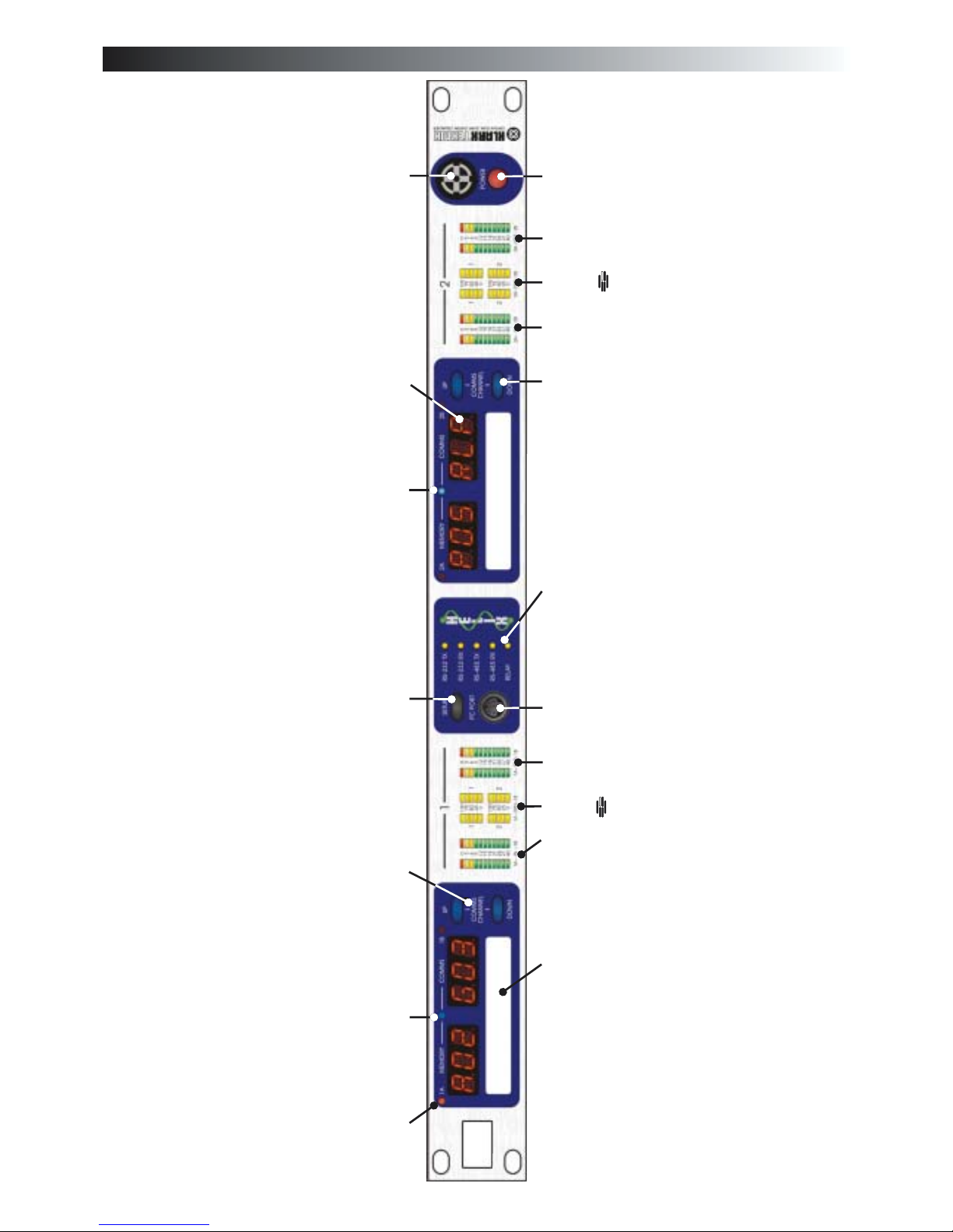
Identification of controls:DN9344
Power switch
Power on indicator
Section 2 input metering
incorporating multi-point clip
indication. This meter indicates the
level immediately after the input gain
trim.
Section 2 output metering
incorporating multi-point clip
indication. This meter indicates the
actual output level from the unit, while
the red clip light indicates internal
clipping, which is monitored at every
internal processing stage.
Section 2 dynamic EQ
metering. Four separate meters are
provided, to allow continuous
monitoring of all dynamic EQ
sections.
SETUP key. Press and hold to enter
SETUP menu. The setup menu is used to
select communications channel (address)
for remote control, and to enable contact
closure operation. Note that each DN9344
has TWO independent communications
channels (one for Section 1 and one for
Section 2) as it contains the equivalent of
TWO DN9340 master units. The
Communications Mode display will flash,
indicating that it can be changed using the
UP and DOWN keys. A momentary press
of the SETUP key will toggle between the
display of the electronic scribble-strips and
display of Last Memory Recalled and the
Communications Mode (which will not
flash indicating thatit cannot bechanged).
The large red alphanumeric displays can be
used to show electronic scribble-strip
information, Last Memory Recalled, and
Communications Mode. In remote control
mode, the displays show a 3-character
name foreach audio channel. This name is
set from the master unit. In relay (contact
closure) mode or stand-alone mode the
displays show Last Recalled Memory and
Communications Mode.
T-DEQ
37
Page 46

l abc
Identification of controls:DN9344
Section 1 input metering
incorporating multi-point clip
indication. This meter indicates the
level immediately after the input gain
trim.
Section 1 output metering
incorporating multi-point clip
indication. This meter indicates the
actual output level from the unit, while
the red clip light indicates internal
clipping, which is monitored at every
internal processing stage.
Section 1 dynamic EQ
metering. Four separate meters are
provided, to allow continuous
monitoring of all dynamic EQ
sections.
Remote ControlActive indicator (green) for Channel 1A, 1B,2Aand 2B. This shows that the master unit is currently
controlling this channelby remote control. These greenlamps are oftenreferred to asthe “me” lights.
Display mode indicator (blue) for
Section 2. When lit this indicates that
the large red displays arenow showing
Last Memory Recalled and
Communications Mode. When not lit,
the displays are showing electronic
scribble-strip names. In this case the
left-hand three characters show the
name of ChannelA and the right-hand
three the name of Channel B, for each
of the twosections.
UP and DOWN keys for Section 2.
Used to select communications
channel (address) for remote control
and also contact closure mode.
Active only when in SETUP menu
(press and hold SETUP to enter this
menu).
T-DEQ
38
Page 47

l abc
Identification of controls:DN9344
PC port connector. Use with the
supplied cable to install software
updates or to control the unit from an
external computer. This connector is
entirely separate from the rear panel
RS-485 connectors, and can be used at
the same timeas the rearpanel ports.
Communications traffic indicators.
These indicate when there is activity
on any of the external interfaces.
Transmit and receive data are shown
for front panel (RS-232) and rear panel
(RS-485) data, and also the contact
closure (RELAY)input.
Scribble-strip areas to allow easy
labelling of the unit. Use only
chinagraph pencils to avoid
permanently marking the unit.
Remove chinagraph markings by
wiping with a soft cloth. Do not use
solvents as these may damage the
surface.
UP and DOWN keys for Section 1.
Used to select communications
channel (address) for remote control
and also contact closure mode.
Active only when in SETUP menu
(press and hold SETUP to enter this
menu).
39
Page 48

l abc
Connections:DN9344
Mains inlet unit is auto
sensing over the range 100-
240VAC.
RS-485 serial
communications.
These connectors are
connected in “loop
through” fashion, so
either may be used for
input or output.
Connectors are
balanced with:
Pin 2 Hot
Pin 3 Cold
Pin 1 Ground
Audio connectors for
channel 2 B.
Electronically
balanced with:
Pin 2 Hot
Pin 3 Cold
Pin 1 Ground
Audio connectors for
channel 1 B.
Electronically
balanced with:
Pin 2 Hot
Pin 3 Cold
Pin 1 Ground
Audio connectors for
channel 2A.
Electronically
balanced with:
Pin 2 Hot
Pin 3 Cold
Pin 1 Ground
Audio connectors for
channel 1A.
Electronically
balanced with:
Pin 2 Hot
Pin 3 Cold
Pin 1 Ground
Contact Closure (RELAY) interface. This allows a simple
contact closure to recall memories on the unit. Pin
connections are asfollows:
Pin 1 -recall Preset /User 1 on Section 1 (the left-handunit)
Pin 2 -recall 2 on Section1 (the left-handunit)
Pin 3 -recall 3 on Section1 (the left-handunit)
Pin 4 -recall 4 on Section1 (the left-handunit)
Pin 5 -recall 1 on Section2 (the right-handunit)
Pin 6 -recall 2 on Section2 (the right-handunit)
Pin 7 -recall 3 on Section2 (the right-handunit)
Pin 8 -recall 4 on Section2 (the right-handunit)
Pin 9 -common
Momentarily connect pin 9 to the appropriate other pin (1-8)
to perform arecall.
Preset / User
Preset / User
Preset / User
Preset / User
Preset / User
Preset / User
Preset / User
40
Page 49

l abc
Signal flow
INPUT
LEVEL
DELAY
FILTERS
DYNAMIC
EQ
PARAMETRIC
EQ
GRAPHIC
EQ
IN 1A
OUT 1A
INPUT
METER
DYNAMIC EQ
METERS
OUTPUT
METER
STEREO LINK
CLIP DETECT
CLIP DETECT
INPUT
LEVEL
DELAY
FILTERS
DYNAMIC
EQ
PARAMETRIC
EQ
GRAPHIC
EQ
IN 1B
OUT 1B
INPUT
METER
DYNAMIC EQ
METERS
OUTPUT
METER
CLIP D
ETECT
CLIP DETECT
INPUT
LEVEL
DELAY
FILTERS
DYNAMIC
EQ
PARAMETRIC
EQ
GRAPHIC
EQ
IN 2A
OUT 2A
INPUT
METER
DYNAMIC EQ
METERS
OUTPUT
METER
STEREO LINK
CLIP DETECT
CLIP DETECT
INPUT
LEVEL
DELAY
FILTERS
DYNAMIC
EQ
PARAMETRIC
EQ
GRAPHIC
EQ
IN 2B
OUT 2B
INPUT
METER
DYNAMIC EQ
METERS
OUTPUT
METER
CLIP D
ETECT
CLIP DETECT
41
Page 50

l abc
Operation DN9344: Remote control mode
This section describes setting up the DN9344 for remote control operation. Please refer to the DN9340
remote control section (on page 32) for information on controlling the system once it is set up.
Press and hold the SETUP button to enter the SETUP menu. Note that the red alphanumeric
displays are now showing Last Recalled Memory and Communication (COMMS) mode. The
blue display mode indicator lights to emphasise this fact. The UP and DOWN buttons light to
show that they are now active.
Press UP and DOWN on the left-hand half of the unit (Section 1) to select the desired
communications channel. There are 32 possible channels available. Each unit (including the
master) MUST have aunique channel number or the system will not work correctly.
Now press the UP and DOWN buttons on the right-hand half of the unit to select its own,
independent communications channel. The reason for having two separate channel numbers
within one unit is that the DN9344 is seen by the system management software as representing
two individual DN9340 units, each with two channels. This allows DN9340 and DN9344 units
to be freely swapped in and out of the system without changing the mapping between audio
channels and communications channels. In other words, every stereo pair of audio channels
has a communications address, irrespective of whether it is a DN9340 or half a DN9344.
The red alphanumeric displays are now showing the three-character name for each audio
channel. These are set from the master unit. If no names have been entered, the display will
show “---”
Press SETUP to confirm (unit will display password menu). PressSETUP to exit.
42
Page 51

l abc
Operation DN9344: Contact Closure (RELAY) mode
This section describes setting up the DN9344 for relay operation. This allowsmemories to be recalledusing a
simple contact closure mechanism.
Press and hold the SETUP button to enter the SETUP menu. Note that the red alphanumeric
displays are now showing Last Recalled Memory and Communication (COMMS) mode. The
blue display mode indicator lights to emphasise this fact. The UP and DOWN buttons light to
show that they are now active.
Use the UP and DOWN keys to select either “RLP” or “RLU” for preset or user memory recall
modes.
Note that the left-hand (Section 1) and right-hand(Section 2) parts of the unitare entirely
independent. It is possible to use either RELAY mode on Section 1 while Section 2 is
operating in remote control mode, or vice versa. Equally, both sections can operate in
either RELAYmode if desired.
Memory recalls are now performedby an externalswitch orrelay which momentarilyconnects
pin 9 of the RELAYconnector to one of the other pins.
Function assignments are as follows:
Pin 1 - recall 1 on Section 1 (the left-hand unit)
Pin 2 - recall 2 on Section 1 (the left-hand unit)
Pin 3 - recall 3 on Section 1 (the left-hand unit)
Pin 4 - recall 4 on Section 1 (the left-hand unit)
Pin 5 - recall 1 on Section 2 (the right-hand unit)
Pin 6 - recall 2 on Section 2 (the right-hand unit)
Pin 7 - recall 3 on Section 2 (the right-hand unit)
Pin 8 - recall 4 on Section 2 (the right-hand unit)
Pin 9 - common
Momentarily connect pin 9 to the appropriate other pin (1-8) to perform a recall.
Press SETUP to confirm (unit will display password menu). PressSETUP to exit.
Preset / User
Preset / User
Preset / User
Preset / User
Preset / User
Preset / User
Preset / User
Preset / User
43
Page 52

l abc
Operation DN9344: Stand alone mode
To prevent any changes to the settings in the unit, set the Communications Mode to OFF.
Press and hold the SETUP key to enter the SETUP menu.
Use the UP and DOWN keys to select OFF foreach section of the unit.
Press SETUP to confirm (unit will display password menu). PressSETUP to exit.
44
Page 53

l abc
45
Over the years a number of professional audio products have provided dynamic equalisation functions of
various types. What all these systems have in common is that the frequency response of the device varies
depending on the signal level. Many units are based on compressor / expander technology with frequency
selection, and the controls often resemble those of a dynamics processor.
The system developed by the Klark Teknik research and development team for the Helix series is rather
different. It draws on KT's unrivalled experience in equalisation, and uses the signal level to directly control
parametric equalisers. This purely EQ-based solution allows simple controls that directly relate to the signal
levels. As a result, it is very easy to set the point at which the dynamic EQ starts to operate, and also to set
precisely its maximum effect. We refer to this technique as “Threshold Dependent Equalisation”.
In order to understand the operation, let us first consider a conventional parametric EQ section (Figure 1).
The three controls available to us are frequency,Q (or bandwidth), and the amount of cut or boost.
This shows a series of responses for the parametric EQ with different input levels. As expected, there is no
change in the shape of the curve with different input levels. If the input is 10dB louder, the output is 10dB
louder at every frequency.
Application note 1: Dynamic EQ
Figure 1 standard parametric EQ 04/12/02 11:05:08
-40
+20
-30
-20
-10
+0
+10
d
B
u
10 20k20 50 100 200 500 1k 2k 5k 10k
Hz
Application notes
T-DEQ
Page 54

If we now replace the parametric with a Helix equaliser and select the dynamic EQ, we have some additional
controls. Frequency and Q controls are as before, but now we have two pairs of controls replacing the single
cut and boost control; these are [low threshold] / [low level], and [high threshold] / [high level]. If we set the
frequency and Q controlsto thearea thatwe wishto control,then the processor will monitor the signal level in
that frequency range. If the signal level in this part of the spectrum is below the [low threshold] setting, then
the unit considers this a ‘quiet’ signal. The EQ applied to the signal will be controlled by the [low level]
control. If the signal level is above the [high threshold] level, then the unit considers this a ‘loud’signal, and
will apply the amount of EQ set by the [high level] control. If the signal level is between the two thresholds,
then the equaliser will seamlesslymorph betweenthe two equalisersettings inreal time. Manual control over
attack and release times is available to set the speed of response to suit the application.
As an example, consider Figure 2, which shows the Helix applying a boost at low signal levels which is
automatically ‘wound out’at high level.
Figure 2 Helix with boost at low signal level 04/12/02 10:08:20
-40
+15
-35
-30
-25
-20
-15
-10
-5
+0
+5
+10
d
B
u
10 20k20 50 100 200 500 1k 2k 5k 10k
Hz
In this example, [low threshold] is -20dBu, [low level] is +12dB, [high threshold] is set to -5dBu, and [high
level] is 0dB. Thus the lowest trace shows an input at -25dBu with a standard parametric boost of +12dB at
1kHz. The -20dBu trace shows an identical response, as expected. However, once above this level, the filter
gradually fades out with increasing signal, until at all levels above 0dBu, the response is flat.
The shape of the curves for -5dBu and -10dBu require some explanation. These appear as they do because of
the nature of the frequency sweep measurement. The Helix equaliser uses a copy of the actual filter in use for
its level calculation, so that depending on the Q of the filter, our input signals are ‘ignored’ as we move away
from the centre frequency by the correct amount. Thus as the sweep measurement moves across the centre
frequency (1kHz in this case), the dynamic EQ is ramping smoothly in and out again, leading to the curves in
Figure 2. Note that if the levelis outside the range specifiedby the two thresholds,the unit behaves likea fixed
parametric EQ. This means that we do not have to guess how much EQ will eventually be applied - it is
explicitly set in advance.
46
l abc
Page 55

Without changing modes or making any other selections, we can make the unit operate ‘the other way up’ just
by selecting suitable values for the two thresholds and levels see Figure3.
In this case, [low threshold] is -20dBu, [low level] is 0dB, [high threshold] is -5dBu, and [high level] is
+12dB, so that instead of cutting this frequency range as the level increases, we are now boosting it. Again,
we have precise control over the maximum amount of boost that will be applied, and the level at which this
will occur. Note the shape of the curve for -5dBu, which has ‘expected values’ outside the filter range and at
the centre frequency, but intermediate values that show the EQ ramping in and out either side of the centre
frequency.
Needless to say, there is no requirement for one of the levels to be 0dB. Figure 4 shows the transition from a
+12dB boost at low level to a -12dB cut at high levels. Again, the intermediate curves show the effect of the
sweep signal moving in and out of the ‘area of interest’of the level detector as the curve is formed.
Figure 3 Helix with boost at high signal level 04/12/02 10:56:55
-40
+20
-30
-20
-10
+0
+10
d
B
u
10 20k20 50 100 200 500 1k 2k 5k 10k
Hz
Helix with boost at low level and cut at high level 04/12/02 11:01:17
-40
+15
-35
-30
-25
-20
-15
-10
-5
+0
+5
+10
d
B
u
10 20k20 50 100 200 500 1k 2k 5k 10k
Hz
47
l abc
Page 56

Application note 2 :What do we mean by all these Q types?
The “Q” of an audio equaliser describes the steepness of the filter - the degree to which it will affect signals
either side of its nominal or “centre” frequency. In general, theQ of a peaking filter is defined mathematically
as , where the bandwidth (in Hz) is the range of frequencies affected by the filter.
Because the frequency response of such a filter is a smooth curve (not a sharp “brick wall” filter like the ones
in an analogue-to-digital converter) we have to decide how we choose to define the bandwidth, and the
established convention is that we use the bandwidth to the “-3dB” points on either side of the centre
frequency, where the gain is 3dB less than the maximum gain.
In the example above, the filter is centred on 1 kHz, the lower 3dB point is at approximately 800 Hz, and the
upper one is at approximately 1.25 kHz.
This filter therefore has a Q of
In a typical parametric equaliser (andin the caseof the Helix systemthe graphic anddynamic sections too) we
have a manual control for the Q of the filter, and this allows us to set any Q that we require. In general high-Q,
narrow filters are used for notching out problem frequencies without affecting the programme material too
much, while gentler low-Q filters are useful for adjusting the tonal balance. In the case of graphic equalisers
there is another issue - that of interaction between adjacent bands. In general, lower-Q filters will blend
together more smoothly, but higher-Q filters provide more selective control of problems - at the expense of
more frequency response ripple.
So far so simple - but why the different types? This is due tothe wayin which the Q of the filter varies (or not)
when the gain control is adjusted. There are three modes available in the Helix system, which we term
Proportional, Constant, and Symmetrical Q.
.
bandwidth
frequencycentre _
2.2
)8001250(
1000
=
-
48
l abc
Klark Teknik 06/19/02 17:16:50f=1.00kHz Q=2.2 Level= +12dB
-12
+12
-10
-8
-6
-4
-2
+0
+2
+4
+6
+8
+10
d
B
u
20 20k50 100 200 500 1k 2k 5k 10k
Hz
3dB
Bandwidth
Page 57

Proportional Q
Proportional Q is the mode of operationfamiliar to users of theKlark Teknik analogue graphic equaliserssuch
as the DN360. As the amount of cut or boost is increased, the Q also increases. This has the effect of making
the equaliser “focus” more tightly as the amount of EQ is increased. This allows a fairly low-Q filter at small
cut and boost settings, providing gentle control of tonal balance and low ripple. At high gain settings, a
proportional-Q equaliser “automatically” increases Q formore dramatic problem solvingsuch as suppression
of feedback or unwanted resonances. In the interests of clarity, the Q setting shown on the display is the Q at
full cut or boost - the Q at lower gain settings will be lower than that shown on the panel.
Constant Q
Aconstant Q equaliser has thesame Q at all cutand boostsettings. In other words, thebandwidth betweenthe
3dB points does not change at all as the gain is adjusted.The really important thing to notice about this is that
the resulting frequency response is NOT symmetrical in cut and boost. This is because of the definition of Q
which is based on the 3dB points The maximum gain of the filter when in cut is, of
course, 0dB, and the bandwidth is determined by the -3dB points and NOT relative to the
minimum gain (at the centre frequency). This makes a lot of sense musically too - if you listen to a music
signal and apply a notch filter, and then change the shape of the curve around theminimum gain (centre) point,
it will make little difference to the sound (since that area is already attenuated a lot). However, if you change
the curve aroundthe 3dB points, this will affect the sound much more, as more or less of the signal “falls into”
the notch. It is bandwidth thatthe constant-Q filteris keeping constant.Note that manyequalisers that are
described as “Constant Q” by their manufacturers do NOT fall into this category, and are what we would term
symmetrical-Q designs.
relative to maximum gain.
relative to 0dB
this
49
l abc
Klark Teknik 06/17/02 12:38:05Proportional Q
-12
+12
-10
-8
-6
-4
-2
+0
+2
+4
+6
+8
+10
d
B
u
20 20k50 100 200 500 1k 2k 5k 10k
Hz
Klark Teknik 06/19/02 10:41:39Constant Q
-12
+12
-10
-8
-6
-4
-2
+0
+2
+4
+6
+8
+10
d
B
u
20 20k50 100 200 500 1k 2k 5k 10k
Hz
Page 58

50
l abc
Symmetrical Q
This class of equaliser has the same curves in boost as the constant-Q type, but then has cut responses that are
symmetrical with the boost ones. In other words, the bandwidth in cut is defined not according to our usual
definition of Q (see constant-Q above) but as “the point were the signal is cut by 3dB less than the maximum
cut”. Most equalisers described by their manufacturers as “Constant Q” in fact produce symmetrical
responses.
Klark Teknik 06/19/02 10:53:43Symmetrical Q
-12
+12
-10
-8
-6
-4
-2
+0
+2
+4
+6
+8
+10
d
B
u
20 20k50 100 200 500 1k 2k 5k 10k
Hz
Page 59

l abc
Technical Specifications: DN9340
Inputs Two
Outputs Two
Performance
Processing (Per Channel)
Input Gain
Delay
Filters
Dynamic EQ
Parametric EQ
Graphic EQ
Power Requirements
Terminations
Type Electronically balanced (pin 2 hot)
Impedance (Ohm) 20k
Common Mode >80dB @ 1 kHz
Rejection
Type Electronically balanced (pin 2 hot)
Maximum Level +21dBu into >2k
Frequency response 0.3dB with all filters and EQ flat
(20Hz to 20kHz)
Distortion (THD+N) @ +4dBu <0.01%
(20Hz to 20 kHz)
Dynamic range 115dB
(20Hz-20kHz unweighted)
+12dB to 40dB in 0.1dB steps plus Off
0-1 second (342.25 m or 333'10” at 20C in 20.8us steps)
4 Filters (max)
Types Low Pass, High Pass, Low Shelf, High Shelf, Notch
2 Bands (max)
Range 12dB
Responses Proportional, Constant, Reciprocal
12 Bands (max)
Range 12dB
Responses Proportional, Constant, Reciprocal
31 Bands On ISO standard frequencies
Range 12dB
Responses Proportional, Constant, Reciprocal, DN27, DN360
Voltage 90V to 250V a.c. 50/60 Hz
Consumption
Audio inputs/outputs 3-pin XLR
RS-485 inputs/outputs 3-pin XLR
RS-232 8-pin Mini-DIN socket (front)
9-pin D-type (rear)
Power 3-pin IEC
60W
Dimensions
Weight
Width 483 mm (19inch)
Height 88 mm (3.5 inch) 2RU High
Depth 303 mm (12 inch)
Nett 5.5kg
Shipping 7.0kg
51
PUSH
PUSH
PUSH
CAUTION: TO REDUCE RISK OF FIRE, REPLACE WITH SAME TYPE OF FUSE.
100-240V
FUSE: 5x20mm
T0.5L250V
AC~50-60Hz 60W
SUPPLY
VOLTAGE
CUS
A
GRAPHIC
PARAMETRIC
DYNAMIC
FILTERS
BYPASS
SELECT
A
B
TYPE
CHAN
IN
DYN
OUT
0
0
3
3
6
6
9
9
12
100
75
50
25
0
100
75
50
25
0
12
15
15
18
18
21
21
24
24
27
27
40
40
1
1
2
2
HOME
(SETUP)
RECALL
STORE
B
B
A
A
B
-
-
-
-
-
-
DN9340
DIG
IT
AL EQUALISER
Page 60

l abc
Technical Specifications: DN9344
Inputs Four
Outputs Four
Performance
Processing (Per Channel)
Input Gain
Delay
Filters
Dynamic EQ
Parametric EQ
Graphic EQ
Power Requirements
Terminations
Dimensions
Weight
Type Electronically balanced (pin 2 hot)
Impedance (Ohm) 20k
Common Mode >80dB @ 1 kHz
Rejection
Type Electronically balanced (pin 2 hot)
Maximum Level +21dBu into >2k
Frequency response 0.3 dB with all filters and EQ flat
(20Hz to 20kHz)
Distortion (THD+N) @ +4dBu <0.01%
(20Hz to 20 kHz)
Dynamic range 115dB
(20Hz-20kHz unweighted)
+12dB to 40dB in 0.1dB steps plus Off
0-1 second (342.25 m or 333'10” at 20C in 20.8us steps)
4 Filters (max)
Types Low Pass, High Pass, Low Shelf, High Shelf, Notch
2 Bands (max)
Range 12dB
Responses Proportional, Constant, Reciprocal
12 Bands (max)
Range 12dB
Responses Proportional, Constant, Reciprocal
31 Bands On ISO standard frequencies
Range 12dB
Responses Proportional, Constant, Reciprocal, DN27, DN360
Voltage 90V to 250V a.c. 50/60 Hz
Consumption 60W
Audio inputs/outputs 3-pin XLR
RS-485 inputs/outputs 3-pin XLR
RS-232 8-pin Mini-DIN socket (front)
Relay Socket 9-pin D-type (rear)
Power 3-pin IEC
Width 483 mm (19 inch)
Height 44 mm (1.75 inch) 1RU High
Depth 287 mm (12 inch)
Nett 5.5kg
Shipping 7.0kg
0
0
3
3
6
6
9
9
12
100
75
50
25
0
100
75
50
25
0
12
15
15
18
18
21
21
24
24
27
27
40
40
1
1
2
2
0
0
3
6
3
6
9
9
12
100
75
50
25
0
100
75
50
25
0
12
15
15
18
18
21
21
24
24
27
27
40
40
1
1
2
2
DN9344DUAL SLAVE DIGITAL EQUALISER
PUSH
PUSH
PUSH
PUSH
PUSH
INOUT
100-240V
FUSE: 5x20mm
T0.5L250V
AC~50-60Hz 60W
COMMS
SUPPLY
VOLTAGE
CUS
52
Page 61

BATTERY REPLACEMENT
Danger of explosion if battery is incorrectly placed. Replace only with the same or equivalent type
recommended by the manufacture. Discard used batteries according to the manufacturer’s instruction.
Lithiumbatteri. Ekxplosionsfare ved feijlagtig handtering af samme fabrikat og type. Lever det brugte batteri
tilbage till leverandoren.
Caution!:
Advarsel!:
l abc
Service information
53
Page 62

Klark Teknik Group DOC02-Helix System 04/06/03
 Loading...