


Remote Control Software
HELIX DN9848E
Remote Control Software V4.01
User Guide

HELIX DN9848E Remote Control Software
User Guide
Contact Details
Klark Teknik
Klark Teknik Building
Walter Nash Road
Kidderminster
Worcestershire
DY11 7HJ
England
Tel: +44 1562 741515
Fax: +44 1562 745371
Email: info@uk.telex.com
Websites: www.klarkteknik.com
HELIX DN9848E Remote Control Software V4.01 User Guide
DOC00056-HELIXRCS Issue B - September 2006
© Telex Communications (UK) Limited.
In line with the company’s policy of continual improvement, specifications and function may be subject to change without notice. This User Guide was correct at the time of writing. E&OE.
2

HELIX DN9848E Remote Control Software
User Guide
CONTENTS
1 |
INTRODUCING THE HELIX DN9848E REMOTE CONTROL SOFTWARE |
........................... 6 |
|
2 |
INSTALLING THE HELIX DN9848E RCS ADD-IN ................................................. |
7 |
|
2.1 |
Minimum System Requirements...................................................................................... |
7 |
|
2.2 |
Software Installation..................................................................................................... |
8 |
|
3 |
GETTING STARTED ..................................................................................... |
10 |
|
3.1 |
Opening HELIX DN9848E RCS within the ELGAR Library Manager ....................................... |
10 |
|
3.2 |
Using the Screens........................................................................................................ |
13 |
|
3.2.1 Overview of FastNav® menus ................................................................................. |
13 |
||
3.2.2 |
Navigation........................................................................................................... |
14 |
|
3.2.3 |
Tool tips.............................................................................................................. |
14 |
|
3.2.4 Using the on-screen controls .................................................................................. |
14 |
||
3.2.5 |
Changing a name ................................................................................................. |
16 |
|
3.3 |
The HELIX DN9848E RCS Workspace.............................................................................. |
17 |
|
3.3.1 |
FastNav® unit bar................................................................................................. |
18 |
|
3.4 |
Quick Tour of the HELIX DN9848E RCS Menu Screens....................................................... |
19 |
|
3.4.1 |
Memory View screens ........................................................................................... |
20 |
|
3.4.2 Copy Channel View screen ..................................................................................... |
23 |
||
3.4.3 DN9848E Units Home screen.................................................................................. |
25 |
||
3.4.4 |
Input Groups screen ............................................................................................. |
26 |
|
3.4.5 |
Output Groups screen ........................................................................................... |
27 |
|
3.5 |
Working Online ........................................................................................................... |
28 |
|
3.5.1 |
Communications Overview..................................................................................... |
28 |
|
3.5.2 |
Online Operation .................................................................................................. |
29 |
|
3.5.3 |
Troubleshooting ................................................................................................... |
31 |
|
3.6 |
Protecting System Settings ........................................................................................... |
32 |
|
3.6.1 |
Panel Locks ......................................................................................................... |
32 |
|
3.6.2 |
System Protect .................................................................................................... |
33 |
|
4 |
INPUT CHANNELS ....................................................................................... |
34 |
|
4.1 |
Input Channel Control Panel.......................................................................................... |
34 |
|
4.2 |
PEQ and Protection Screens .......................................................................................... |
35 |
|
4.3 |
Setting Input Parameters.............................................................................................. |
36 |
|
4.3.1 Naming an Input Channel ...................................................................................... |
36 |
||
4.3.2 |
Gain and Delay .................................................................................................... |
36 |
|
4.3.3 |
Parametric equalization (PEQ) ................................................................................ |
37 |
|
4.3.4 |
Compression (channel protection)........................................................................... |
37 |
|
3

|
|
HELIX DN9848E Remote Control Software |
|
|
|
|
User Guide |
4.4 |
Monitoring the Input Signals ......................................................................................... |
38 |
|
4.4.1 |
Meters - peak ...................................................................................................... |
38 |
|
4.4.2 Meters – gain reduction......................................................................................... |
38 |
||
4.4.3 |
Input Response graph ........................................................................................... |
39 |
|
5 |
OUTPUT CHANNELS..................................................................................... |
40 |
|
5.1 |
Output Channel Control Panel........................................................................................ |
40 |
|
5.2 |
Filters, PEQ and Dyn. Screens ....................................................................................... |
41 |
|
5.3 |
Setting Output Parameters............................................................................................ |
42 |
|
5.3.1 Naming an Output Channel .................................................................................... |
42 |
||
5.3.2 |
Routing Page ....................................................................................................... |
42 |
|
5.3.3 Signal Invert, Delay and Output Level ..................................................................... |
44 |
||
5.3.4 Phase Adjustment (Filters Screen) .......................................................................... |
45 |
||
5.3.5 High Pass and Low Pass Filters (Filters Screen) ......................................................... |
47 |
||
5.3.6 Parametric Equalisation (PEQ Screen)...................................................................... |
49 |
||
5.3.7 |
Compression (Dyn. Screen) ................................................................................... |
51 |
|
5.3.8 Output Limiter (Dyn. Screen) ................................................................................. |
52 |
||
5.4 |
Monitoring the Output Signals ....................................................................................... |
53 |
|
5.4.1 |
Meters - peak ...................................................................................................... |
53 |
|
5.4.2 Meters – gain reduction......................................................................................... |
53 |
||
5.4.3 |
Output Response graph ......................................................................................... |
53 |
|
5.5 |
Output Muting on Selected Unit ..................................................................................... |
54 |
|
6 |
CONFIGURING A HELIX DN9848E UNIT .......................................................... |
55 |
|
6.1 |
General...................................................................................................................... |
55 |
|
6.2 |
Unit and Memory Identification...................................................................................... |
56 |
|
6.3 |
Display Delay Options .................................................................................................. |
57 |
|
6.4 |
Knob Mouse Direction .................................................................................................. |
58 |
|
6.5 |
PEQ Bandwidth or Q Selection ....................................................................................... |
59 |
|
7 |
PROGRAMMING EQ ..................................................................................... |
60 |
|
7.1 |
Parametric Equalisation (PEQ) ....................................................................................... |
60 |
|
7.2 |
Dynamics ................................................................................................................... |
62 |
|
7.3 |
Filters ........................................................................................................................ |
63 |
|
8 |
WORKING WITH MULTIPLE HELIX ADD-INS ....................................................... |
64 |
|
8.1 |
Building your Network Remotely .................................................................................... |
64 |
|
8.2 |
The DN9848 Units Home Screen .................................................................................... |
64 |
|
9 |
STORING/RECALLING MEMORY SETTINGS .......................................................... |
67 |
|
9.1 |
Using Working Memories .............................................................................................. |
67 |
|
9.2 |
Unit (Device) Memories ................................................................................................ |
69 |
|
9.3 |
Copy RCS Memories..................................................................................................... |
71 |
|
|
|
4 |
|

HELIX DN9848E Remote Control Software
User Guide
10 MANAGING GROUPS.................................................................................... |
72 |
|
10.1 |
Security – Grouping Password .................................................................................... |
72 |
10.2 |
Input Groups ........................................................................................................... |
74 |
10.3 |
Output Groups ......................................................................................................... |
78 |
11 USING HELIX DN9848E RCS TO CONTROL A PROCESSING SYSTEM ......................... |
82 |
|
11.1 |
Overview................................................................................................................. |
82 |
11.2 |
HELIX DN9848E unit interconnections.......................................................................... |
82 |
11.2.1 |
Connecting the HELIX DN9848E units using the two-port switch............................... |
82 |
11.2.2 |
Connecting the HELIX DN9848E units to an Ethernet switch or hub........................... |
83 |
11.3 |
Ethernet Connection ................................................................................................. |
83 |
11.3.1 |
Ethernet connection – standard ........................................................................... |
83 |
11.3.2 |
Ethernet connection – wireless option................................................................... |
84 |
11.3.3 |
Configuring the Network Devices ......................................................................... |
84 |
11.3.4 |
Fault Finding Tips .............................................................................................. |
91 |
11.4 |
Serial Connection (Option)......................................................................................... |
92 |
11.4.1 |
Serial connection details..................................................................................... |
92 |
11.4.2 |
Connection Procedure ........................................................................................ |
92 |
11.5 |
The System Configuration Window .............................................................................. |
95 |
11.5.1 |
Finding ports and device names........................................................................... |
95 |
11.5.2 |
The Port Configuration screen ............................................................................. |
96 |
12 APPENDICES............................................................................................. |
98 |
||
12.1 |
Glossary of Terms and Abbreviations........................................................................... |
98 |
|
12.2 |
Remote Control Connection Options .......................................................................... |
100 |
|
12.2.1 |
Single-unit serial connections............................................................................. |
100 |
|
12.2.2 |
Multiple-unit Ethernet connections ...................................................................... |
101 |
|
12.2.3 |
Multiple-unit serial connections........................................................................... |
103 |
|
12.2.4 |
Ethernet and serial ........................................................................................... |
104 |
|
12.3 |
Setting up the Lantronix UDS1100 Converter.............................................................. |
105 |
|
12.3.1 |
Configuring the Lantronix UDS1100 .................................................................... |
105 |
|
12.3.2 |
Connecting the system equipment ...................................................................... |
107 |
|
12.4 |
Mix Templates for Routing Pages .............................................................................. |
109 |
|
12.4.1 |
Manual Mix (Routing Reset) ............................................................................... |
109 |
|
12.4.2 |
2 |
X 2 Way Crossover......................................................................................... |
109 |
12.4.3 |
2 |
X 4 Way Crossover......................................................................................... |
110 |
12.4.4 |
2 |
X 3 Way Crossover plus 2 Aux ......................................................................... |
110 |
12.4.5 |
1 |
X 5 Way Crossover plus 3 Aux ......................................................................... |
110 |
12.4.6 |
1 |
X 6 Way Crossover plus 2 Aux ......................................................................... |
111 |
12.4.7 |
4 |
X Bi-Amp...................................................................................................... |
111 |
12.5 |
Presets ................................................................................................................. |
111 |
|
|
|
5 |
|

HELIX DN9848E Remote Control Software
User Guide
1 INTRODUCING THE HELIX DN9848E REMOTE CONTROL
SOFTWARE
The HELIX DN9848E Remote Control Software (HELIX DN9848E RCS) enables engineers to remotely program a system of up to 16 HELIX DN9848E System Controller units from a laptop or PC for onward downloading to the HELIX DN9848E System Controller units at a venue. Hence, programming can be done in advance of a show from home or en route, leaving more time for fine-tuning.
At the venue, the settings can be quickly downloaded to the system. Thereafter, a HELIX DN9848E RCS tablet/laptop PC can be used for real-time control of the system during both set-up and performance. Using the HELIX DN9848E RCS offers an enhanced visual overview of unit performance, as well as significant time-saving in switching between units, navigating ‘processing’ views and adjusting settings. Furthermore, for optimal control during set-up, the tablet/laptop PC can be set up to communicate with the system over a wireless connection, leaving the engineer free to move around the venue while adjusting the processor settings. For performance, Ethernet communication is used, although there is an option for conventional serial RS-232, if required. Settings can also be uploaded from the HELIX DN9848E System Controller units to the HELIX DN9848E RCS.
In addition to the active settings, HELIX DN9848E RCS can also be used to remotely program the 32 lockable system memories and 5 user memories.
The HELIX DN9848E RCS runs as an Add-In to the Midas Klark Teknik ELGAR Library Manager, enabling you to work on settings for your system controller devices alongside other Midas or Klark Teknik devices, such as a H1000 console or DN9340 and DN9344 EQ units, and save them all in a single show file. The show file can then be reused at subsequent venues. In addition, you can minimise time and effort by copying settings between the HELIX DN9848E RCS Add-In units.
Please note that, for the purposes of this manual, a HELIX DN9848E unit is the actual physical version connected to the system and an RCS unit is a unit in HELIX DN9848E RCS. Also, some of the screenshots in the manual may appear slightly different to those on your screen due to configuration and status of the system, units and your laptop/PC.
Note Earlier DN9848 devices (non-E) may be connected to, and controlled using the HELIX DN9848E RCS provided that the connection to these devices is in accordance with Appendix 12.2 of this User Guide.
6

HELIX DN9848E Remote Control Software
User Guide
2INSTALLING THE HELIX DN9848E RCS ADD-IN
2.1Minimum System Requirements
Operating System: |
Windows 2000 or Windows XP |
Computer/Laptop: |
Display resolution minimum 1024 X 768 pixels set at 96 DPI |
|
Pentium III, 500MHz (or equivalent) |
|
256MB RAM |
|
Minimum 10MB of free disk space on hard drive |
Connectivity: |
Connection to the HELIX DN9848E units is via Ethernet (also with wireless |
|
option), with the units operating V4.00 (or later) host code. There is also an |
|
option for serial connection, which is done via the front panel. Full connection |
|
options and respective equipment requirements are detailed in Section 11. |
Software: |
The following software must be installed prior to installing the HELIX DN9848E |
|
Remote Control Software: |
|
Microsoft .NET Framework 1.1 available at: |
|
http://microsoft.com/downloads/details.aspx?FamilyId=262D25E3-F589- |
|
4842-8157-034D1E7CF3A3&displaylang=en |
|
Midas ELGAR Library Manager available at: |
|
http://www.midasconsoles.com |
7
HELIX DN9848E Remote Control Software
User Guide
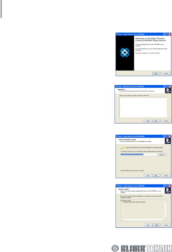
2.2Software Installation
HELIX DN9848E RCS Add-In is provided as an ‘.exe’ file from the Klark Teknik website (www.klarkteknik.com) with an integral Setup Wizard that guides you through the installation process on your laptop/PC.
Note We recommend that you save the .exe file to your desktop - or other holding folder - rather than opening the file while the Internet transfer is in progress. This will avoid the possibility of the integral Setup Wizard interrupting the transfer, especially on slower internet connections.
After you have downloaded the .exe file, install it on your laptop/PC as follows:
1Run the “DN9848ERCS_Vn_nn.exe” file (where “n_nn” is the latest software version). The Setup Wizard should appear on-screen within a few seconds.
2Following the on-screen instructions, click  to go to the Information window, which details the latest improvements to the software. Previous users may find this information particularly useful.
3Click  to go to the Select Desination Location window. Leave the Destination Directory as the preset default, that is, “C:\Program Files\Klark Teknik Group\ELGAR”, unless you have installed ELGAR in an alternative directory. In the latter case, specify your alternative ELGAR destination directory.
4Click  once again; this will take you to the Ready to Install window.
8

HELIX DN9848E Remote Control Software
User Guide
5When you are ready to install, click  . After successful installation, click
  to exit the Wizard. The HELIX DN9848E RCS will now be available through the ELGAR Library Manager.
9
HELIX DN9848E Remote Control Software
User Guide
3GETTING STARTED
3.1Opening HELIX DN9848E RCS within the ELGAR Library Manager
Note To run HELIX DN9848E RCS you must have the Midas Klark Teknik ELGAR Library Manager installed on your laptop/PC. The ELGAR Software and User Guide may be obtained from our website at www.midasconsoles.com.
Note To use the HELIX DN9848E RCS to control a processing system, see section 11 for details on Ethernet connection, setting up and configuration, and section 3.5 for online operation.
HELIX DN9848E RCS runs as an Add-In to the ELGAR Library Manager, which provides a single management window for various Midas and Klark Teknik remote programming software applications.
By opening multiple Add-Ins within the ELGAR Library Manager you can work on settings for the various Midas and Klark Teknik devices associated with a show at the same time. For example, you can have a series of Klark Teknik HELIX DN9848E System Controller Add-Ins to cover your system, plus a Midas Heritage 1000 Add-In with settings for a H1000 console and a series of HELIX DN9340 Digital EQs. Furthermore, as the concurrently opened Add-Ins are saved, reopened etc., as a single show file using the ELGAR File menu commands, you will save time in file management.
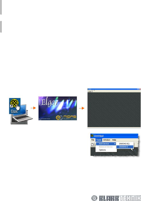
To add HELIX DN9848E RCS devices to the ELGAR Library Manager
1 Open ELGAR by double clicking on the ELGAR icon on your desktop.
2From the ELGAR main menu bar, select Tools >
Add Device > DN9848 E.
10
HELIX DN9848E Remote Control Software
User Guide
3At the Add Multiple DN9848 E Devices window, use the Number of Devices to Add drop down list to select the number of devices, you wish to add,
up to a maximum 16. For example, 9.
4 Click OK to add the devices.
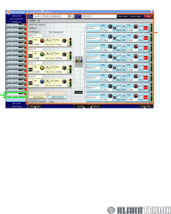
A DN9848 Units Home screen (diagram right) is opened inside the ELGAR Library Manager. The HELIX DN9848E RCS units are automatically inserted in FastNav® (highlighted by orange box) and numbered sequentially from 1 upwards. The highest numbered unit is selected.
The DN9848 Units Home screen is the workspace where you remotely program scene EQ settings for your HELIX DN9848E system controllers; see section 3.4.3 for details.
To use the HELIX DN9848E RCS to control a processing system, see section 11 for details on Ethernet connection, setting up, configuration etc., and section 3.5 for online operation.
To add more HELIX DN9848E RCS devices to the ELGAR Library Manager
1From the ELGAR main menu bar, select Tools > Add Device > DN9848 E.
2In the Add Multiple DN9848 E Devices window, select the number of devices you wish to add using the Number of Devices to Add drop down list; this will show only the number of available devices left to add.
3Click OK . These devices are added to the device list (left-hand side of screen), with each new device being allocated the lowest available number. To cancel, click
  at the top right-hand corner of window.
Note Devices can be added/removed, as required, at any time during HELIX DN9848E RCS operation.
11
HELIX DN9848E Remote Control Software
User Guide
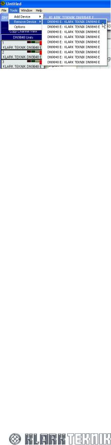
To remove a HELIX DN9848E RCS device from the ELGAR Library Manager
1From the ELGAR main menu bar, select Tools > Remove Device and highlight the device you wish to remove from the list. (You can rename each device for easy identification; see section 3.2.5.)
2Release left-hand mouse button. The device will disappear from the device list.
You can only remove one device at a time. Repeat the above steps for any other devices you wish to remove.
12

HELIX DN9848E Remote Control Software
User Guide
3.2Using the Screens
This section provides information on screen navigation and the use of the controls, for example, buttons, control knobs, faders etc.
3.2.1Overview of FastNav® menus
13
HELIX DN9848E Remote Control Software
User Guide
3.2.2Navigation
To move around the screens, click on the buttons in FastNav®; see section 3.2.1. Further screens, such as the input and output response graphs, routing page and those from the buttons on the input and output channel control panels, are all available from the DN9848 Units Home screen; see section 3.4.3.
3.2.3Tool tips
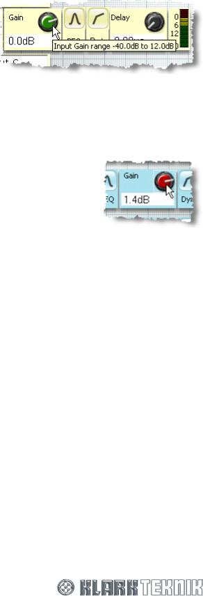
‘Tool tips’ are boxes that appear for a short while underneath the cursor when it pauses over certain objects. These boxes contain a single line of text that gives you useful information on the object, such as the range of adjustment on a control knob (diagram right), the function of a button or the description of a field.
3.2.4Using the on-screen controls
This section gives details on adjusting or resetting the on-screen controls, such as control knobs, faders etc.
To adjust a control knob
1Click on control knob to select it. A dotted box surrounding the object will appear to indicate that it has been selected (see diagram right).
2Once selected you can adjust the control knob’s setting – shown in the white box directly underneath - via the mouse or laptop/PC keyboard; a combination of both may also be useful. The on-screen control knob will rotate and the setting value will alter accordingly.
Mouse: To adjust the value using the mouse, position the cursor within the dotted box and click the left-hand mouse button. Then, while holding down the button, move the mouse to make the required adjustment. The way in which the mouse movements alter the setting depend on the Knob Mouse Direction configuration, see Section 6.4. When you have achieved the required setting value, release left-hand mouse button. If you run out of adjustment due to cursor reaching edge of screen, which may happen on the Delay control knobs due to the large amount of adjustment available, select control knob again and repeat adjustment.
Keyboard: Using certain keys on your laptop/PC keyboard you can adjust the control knob in regular increments (with the exception of frequency, which has a logarithmic scale). The increment value is dependent on control knob function, adjustment range and unit type.
The keys give the following type of adjustment for each control knob, irrespective of Knob Mouse Direction configuration:
Home and End keys take you to the minimum and maximum values, respectively.
Page Up and Page Down keys give coarse adjustment in positive and negative directions, respectively. To protect the system these keys do not function for grouping rotaries.
u and v arrow keys give moderate adjustment in positive and negative directions, respectively. To protect the system these keys do not function for grouping rotaries.
s and t arrow keys give fine adjustment in negative and positive directions, respectively.
14
HELIX DN9848E Remote Control Software
User Guide
To adjust a fader (see section 5.3.2 "Routing Page”)
Just click on fader to select it. Then, while holding down the left-hand mouse button, drag mouse up and down until you have achieved the required value (shown in white box directly underneath fader). Release left-hand mouse button.
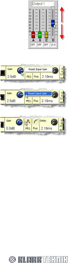
To quickly reset a control knob or fader value to default using the mouse
1Click on control knob or fader using the right-hand mouse button, for example, the “Input D” Gain control knob. A reset option box will appear.
2Move cursor over option box to highlight it.
3Click left-hand mouse button; value reverts to default.
15
HELIX DN9848E Remote Control Software
User Guide
3.2.5Changing a name
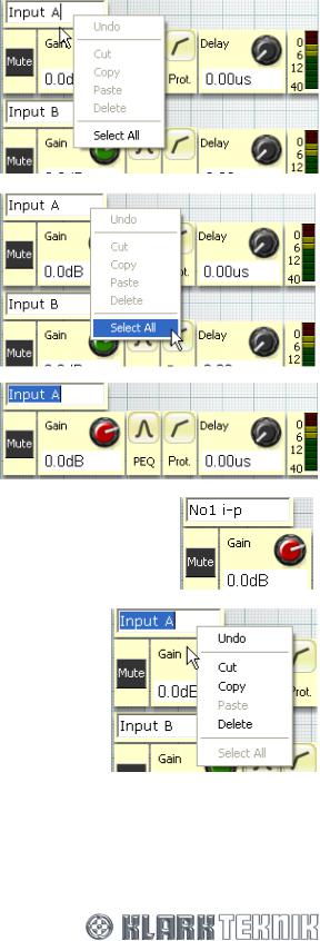
You can change the name of channels, units, memories etc. The following example shows you how to change the name of an input channel but the principle is the same for any other name you wish to alter.
To change a name
1Right click in the field whose name you wish to change. For example, “Input A” control panel on the DN9848 Units Home screen.
2 Move cursor over Select All to highlight it.
3Left click; all of input channel name is highlighted.
4At this point you can type in the new name, for example, “No3 i-p”.
Or:
With the name still highlighted, you can right-click again in the name field to obtain a menu that allows you to:
Undo – undoes previous operation.
Cut – removes highlighted text and stores it ready for a subsequent paste operation.
Copy – copies highlighted text without removing it and stores it ready for a subsequent paste operation.
Paste – pastes stored text.
Delete - removes highlighted text completely without
storing it. Any subsequent paste operation will only paste the stored text from when you last used Cut or Copy.
Please note that some of the above options are dependent on previous actions and current operation, so they may not be available, as indicated by being ‘greyed out’. Also, certain symbols are not allowed, for example, % and £.
16
HELIX DN9848E Remote Control Software
User Guide
3.3The HELIX DN9848E RCS Workspace
The DN9848 Units Home screen (illustrated below) is the default screen when starting up the HELIX DN9848E RCS software. The screen comprises a main workspace area with FastNav® down the left-hand side and four buttons along the bottom. The workspace and FastNav® area alter according to FastNav® button selection, while the four buttons along the bottom are static.
Five buttons in FastNav® emulate the functionality of the HELIX DN9848E. You can open up to 16 HELIX DN9848E units within a single show file, with each one each being allocated a unit bar in FastNav®.
FastNav®: contains the five |
|
|
||
main menu buttons. A list of |
|
|
||
DN9848E units connected to |
Message bar shows the current |
|
||
the system are shown below |
Close window |
|||
main view and unit selected |
||||
DN9848 Units button (DN9848 |
||||
button |
||||
Units Home screen only) |
|
|||
|
|
|||
|
|
|
|
|
|
|
|
|
|
Main workspace
Unit bar, see section 3.3.1
|
Mute All button: |
|
Un-Mute All button: |
|
|
mutes all outputs |
|
unmutes all outputs |
|
|
of all units |
|
of all units |
|
|
|
|
All Units Offline button: |
|
All Units Online button: |
||||
puts all units online |
|
puts all units offline |
||
FastNav® can display the maximum number of units, that is, 16, and shows them sequentially in ascending order (top down).
17

HELIX DN9848E Remote Control Software
User Guide
3.3.1FastNav® unit bar
Each HELIX DN9848E unit in the system has a dedicated unit bar in FastNav® that displays unit information, as detailed in the illustration below. Clicking on a unit bar selects its associated unit.
During online operation, the activity indicators of each RCS unit provide audio metering, which mirror the activity indicators of the HELIX DN9848E unit.
Unit’s unique  identification number
Name of unit 
Signal present indicator |
|||||
Clip in progress |
|
|
Limiter gain reduction |
||
|
|
||||
|
|
||||
indicator |
|
|
indicator |
||
|
|
|
|
|
Online status indicator: mimics |
|
|
|
|
|
|
|
|
|
|
|
|
|
|
|
|
|
Online button in DN9848 Units Home |
|
|
|
|
|
screen, where red indicates offline, |
|
|
|
|
|
green online and yellow |
|
|
|
|
|
unavailable |
Lighter background indicates that this unit is selected
To select a unit
Click on the bar of the required unit under the DN9848 Units button in FastNav®; its background will lighten to indicate it is the current selection. The view containing the input and output channel control panels will appear.
18
HELIX DN9848E Remote Control Software
User Guide
3.4Quick Tour of the HELIX DN9848E RCS Menu Screens
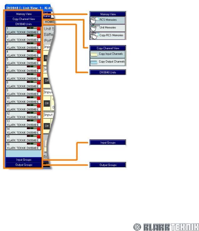
The HELIX DN9848E RCS workspace has five main screens, selectable via buttons in FastNav®:
•Memory View – lets you copy/write working memory to/from HELIX DN9848E unit and RCS unit memories.
•Copy Channel View - lets you copy/paste input and output channels across RCS units.
•DN9848E Units –gives you access to the control panels and response graphs of the input and output channels, and also routing page and passwords.
•Input Groups - lets you manage the input groups by creating and editing them.
•Output Groups - lets you manage the output groups by creating and editing them.
Memory View - see section 3.4.1
Copy Channel View - see section 3.4.2
DN9848 Units - see section 3.4.3
Input Groups - see section 3.4.4
Output Groups - see section 3.4.5
19
HELIX DN9848E Remote Control Software
User Guide
3.4.1Memory View screens
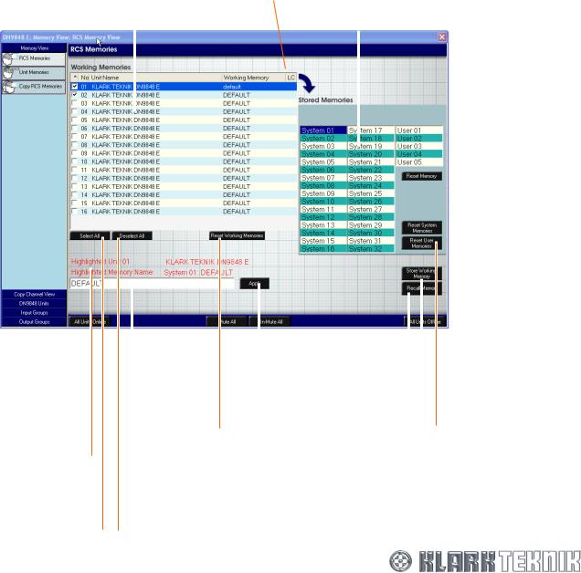
The Memory View has three screens, RCS Memories, Unit Memories and Copy RCS Memories, from which you can manage the system units’ working memory. The screens are described in the following subsections and operations involving the screens are described in detail within Section 9.
Each input has 32 lockable system memories (System 01 to System 32 for storing standard set-ups), five free access user memories (User 01 to User 05 for storing set ups for the current show) and one working memory. Each memory holds a store of 32 packets of memory, numbered from 1 to 32, with each one corresponding to the 32 available system unit slots.
The working memory contains the current working settings for the system units and is stored in the current RCS show file.
RCS Memories screen
The RCS Memories screen lets you store/recall the working memory of selected RCS units to/from one of the system or user memory stores. You can reset working memories, and individual and collective system and user memories on selected units. The RCS Memories screen also allows you to rename the working memory on any RCS units. For a full description see Section 9.
Working Memories list: for |
Locked/Protected |
|
|
|
units are identified |
|
Stored Memories list: |
||
selecting unit(s) from which |
|
|||
by an * in the LC |
|
|||
working memory is copied |
|
memory store locations |
||
|
|
column |
|
(32 system and 5 user) |
|
|
|
||
|
|
|
|
|
|
|
|
|
|
 Reset Memory button: resets selected memory to default
 Reset System Memories button: resets all system memories to default
|
|
|
Apply button: applies |
|
|
|
|
|
|
|
|
|
|
|
|
|
|
|
|
|
memory name change |
|
|
Shows number and |
|
|
on selected units |
|
Reset User Memories button: |
|
|
|
|||
|
Reset Working Memories button: |
|
|||
name of currently |
|
|
|||
highlighted unit and, |
|
resets working memories of |
|
resets all user memories |
|
|
selected units to default |
|
to default |
||
below, selected |
|
|
|||
|
|
|
|
|
|
stored system or user |
|
|
|
|
|
memory number |
|
Allows you to change |
|
|
Store Working Memory |
|
|
|
|
||
|
|
the working memory |
|
|
button: stores working |
|
|
name on selected units |
Recall Memory button: |
|
|
|
|
|
memory of selected units |
||
|
|
||||
|
|
|
recalls selected memory |
|
in selected memory |
Select All button: selects |
Deselect All button: deselects |
to Working Memories list |
|
|
|
|
|
|
|||
all units in above list |
all selected units |
|
|
|
|
20
HELIX DN9848E Remote Control Software
User Guide
HELIX DN9848E Unit Memories
The Unit Memories screen lets you copy corresponding system and user memories between the RCS and the actual physical units in the system. For a detailed description see Section 9.
Units list: for selecting |
|
|
unit(s) that memory is |
Comment field: gives details |
|
copied to/from |
||
on whether the operation is |
||
|
||
|
successful or not |
|
|
|
Locked & Protected units are identified by an * in the LC column
Memories list: unit memory store locations (32 system and 5 user)
Select All button: selects all system and user memories
Unit Progress status bar: shows progress of device memory copying process
Select All button: selects all units in above list
Memory Progress status bar: shows progress of stored memory copying process
Deselect All button: |
|
deselects all selected |
Cancel button: cancels |
units |
memory copying process |
 Deselect All button: deselects all selected system and user memories
 Read From Unit button: reads memories from selected unit(s)
Write To Unit button: writes selected memories to selected unit(s)
21
HELIX DN9848E Remote Control Software
User Guide
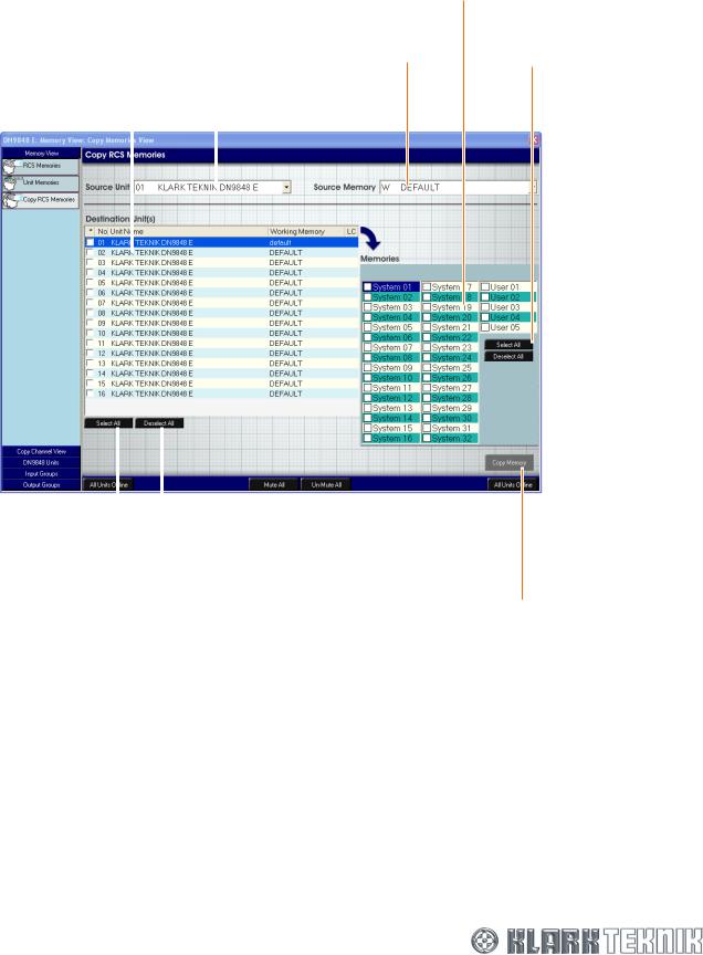
Copy RCS Memories
The Copy RCS Memories screen lets you copy the memory of a single unit, which is stored in the HELIX DN9848E RCS software, to the RCS memories of one or more of the other units in the system.
Source Unit field: for selecting unit from which source memory is copied
Destination Units(s) list: for |
|
|
Source Memory field: for |
|
|||
selecting which unit(s) the |
|
|
selecting memory to |
source memory is copied to |
|
|
copy |
|
|
|
|
|
|
|
|
Memories list: destination memories to which source memory is copied
Select All button: selects all system and user memories
 Deselect All button: deselects all selected system and user memories
Select All button: |
|
Deselect All button: deselects |
selects all destination |
|
all selected destination |
units |
|
units |
Copy Memory button: copies source memory of source unit to selected destination memories of selected destination unit(s)
22
HELIX DN9848E Remote Control Software
User Guide
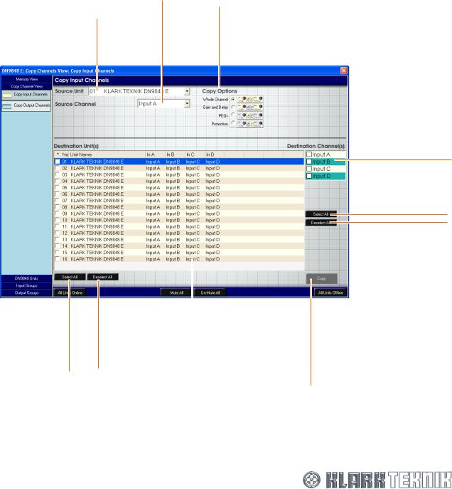
3.4.2Copy Channel View screen
The Copy Channel View screen gives you access to the Copy Input Channels and Copy Output Channels screens. These screens let you copy and paste whole input or output channels or just selected elements from a selected unit to selected channels of other units. A more detailed description of these processes appears within Section 9.
Copy Input Channels screen
The Copy Input Channels screen lets you copy the following from the particular channel of a selected unit to the selected channels of other units: the whole channel; gain, delay and mute settings; PEQs settings; or protection settings.
Source Unit field: for selecting unit from which input channel is copied
Select All button: selects all destination units
Source Channel field: for selecting input channel to copy
Copy Options list: for selecting which audio elements of selected input channel you wish to copy
|
|
|
|
|
|
|
Locked |
|
|
warnings will |
|
|
appear here if |
|
Deselect All button: |
any channels are |
|
deselects all selected |
locked |
|
destination units |
|
|
|
|
|
Destination Unit(s) list: for selecting which units the input channels are copied to
Destination Channel(s) list: for selecting input channels to which source input channel is copied
Select All button: selects all destination units
Deselect All button: deselects all selected destination units
Copy button: copies selected input channel of selected unit to selected destination channel(s) of destination unit(s)
23
HELIX DN9848E Remote Control Software
User Guide
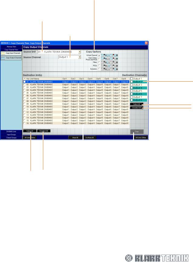
Copy Output Channels screen
The Copy Output Channels screen lets you copy the following from a particular channel of a selected unit to the selected channels of other units: the whole channel; gain, delay, mute and invert phase settings; filter settings; dynamics settings; or PEQ settings.
Source Unit field: for selecting unit from which output channel is copied
Select All button: selects all destination units
Copy Options list: for selecting which audio elements of selected output channel you wish to copy
Source Channel field: for selecting output channel to copy
Destination Channel(s) list: for selecting output channels to which source output channel is copied
Select All button: selects all destination channels
Deselect All button: deselects all selected destination channels
|
|
|
|
|
|
|
|
|
Locked warnings will |
|
|
|
appear here if any |
|
|
Deselect All button: |
channels are locked |
Copy button: copies selected output |
|
deselects all selected |
|
|
|
destination units |
|
|
channel of selected unit to |
|
|
|
selected destination channel(s) of |
|
|
|
destination unit(s) |
|
|
|
|
Destination Unit(s) list: for |
|||
selecting which unit(s) the |
|||
output channels are copied to |
|||
24
HELIX DN9848E Remote Control Software
User Guide
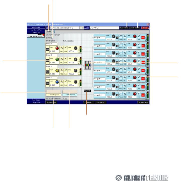
3.4.3DN9848E Units Home screen
For a more detailed description see Section 8.3. Click on the DN9848 Units button to obtain the DN9848E Units Home screen. This screen relates to the currently selected unit and contains the following:
•Input channel control panels (A, B, C and D).
•Output channel control panels (1 to 8, inclusive).
•Unit’s name and number, and the name of the working memory.
•Buttons for accessing DN9848E Unit Home page, input and output channel response graphs, routing page and system password, and ones for muting/unmuting and putting the units online/offline.
•Information sections that provide unit and RCS software, battery and communications port information.
HOME button: returns you here from any of the DN9848 Units sub-screens
Input channel control panel
Input Response button: takes you to the inputs’ overview response graph, see section 4.4.1
Details of the Helix DN9848E RCS software version
Information section |
|
Mute Outputs button: mutes all |
||
|
||||
|
|
outputs on selected unit |
||
|
|
|
Unmute Outputs button: |
|
|
|
|
||
|
|
|
unmutes all outputs |
|
|
|
|
on select unit |
|
|
|
|
|
|
|
|
|
|
|
Online button: puts unit online or offline, button changes colour accordingly
Fader button: gives access to routing pages
Output channel control panel
Passworsds button: password button
Output Response button: takes you to the outputs’ overview response graph, see section 5.4.1
The information section gives information on:
•“Unit SW Version” - the HELIX DN9848E software installed in the physical unit.
•“Battery” – provides information on state of unit’s battery, displaying “Good” or “Low”.
•“PortName” – the name of the port assigned to the current unit, which can be edited and changed in ELGAR, see section 11.3.3.
25
HELIX DN9848E Remote Control Software
User Guide
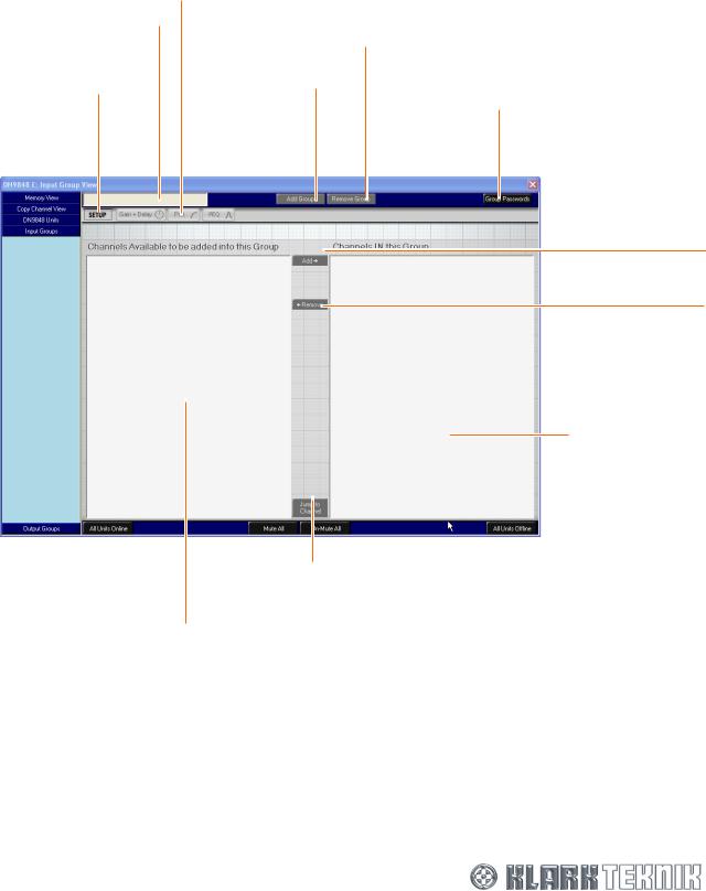
3.4.4Input Groups screen
The Input Groups screen allows you to assign any inputs from the system units to a group. For a full description of the Group management process see Section 10.
Groups can be password protected. The screen below shows the default screen, which has no groups allocated.
Input group name field
SETUP button: takes you input group setup screen
Input function buttons: take you to Gain + Delay, Prot., and PEQ screens
Add Group button: stores currently selected input group
Remove Group button: deletes currently selected input group from store
Group Passwords button: For allocating a password to a group
Add Î button: adds selected inputs(s) to current input group
This section shows the channels available for transfer to input group
Í Remove button: removes selected inputs(s) from current input group
This section shows the channels currently in the selected input group
Jump to Channel button: takes you to the selected units on the DN9848 Units Home screen
26

HELIX DN9848E Remote Control Software
User Guide
3.4.5Output Groups screen
The Output Groups screen allows you to assign any outputs from the system units to a group. For a full description of the Group management process see Section 10.
Groups can be password protected. The screen below shows the default screen, which has no groups allocated.
|
|
|
Output function buttons: |
||
Output group |
|
take you to Gain + Delay, |
|||
|
Filters, PEQ, and Dyn. |
||||
name field |
|
||||
|
screens |
||||
|
|
|
|||
SETUP button: takes |
|
|
Add Group button: |
|
|
|
|
|
|||
|
|
|
|
||
|
|
stores currently |
|
|
|
you output group |
|
|
|
|
|
|
|
selected output |
|
|
|
setup screen |
|
|
|
|
|
|
|
group |
|
|
|
|
|
|
|
|
|
|
|
|
|
|
|
|
|
|
|
|
|
Remove Group button: deletes currently selected output group from store
Group Passwords button: For allocating a password to a group
Add Î button: adds selected outputs(s) to current output group
Í Remove button: removes selected outputs(s) from current output group
This section shows the channels currently in the selected output group
|
|
|
This section shows the |
Jump to Channel button: |
|
takes you to the |
||
channels available for |
selected units on the |
|
transfer to output group |
DN9848 Units Home |
|
screen
27
HELIX DN9848E Remote Control Software
User Guide
3.5Working Online
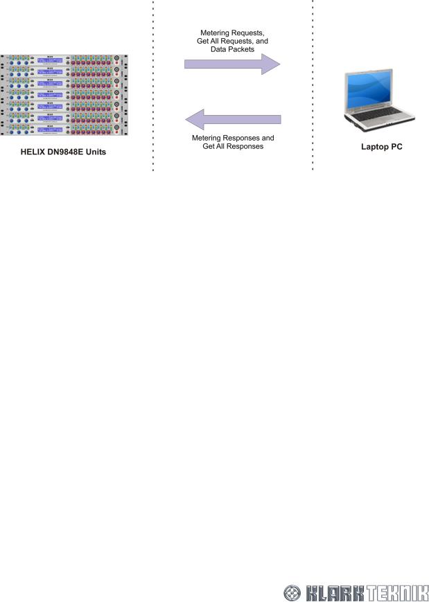
3.5.1Communications Overview
Referring to the illustration above, in online mode the HELIX DN9848E RCS laptop/PC and units exchange the following messages:
Metering Requests |
These obtain data for the Input, Dynamic EQ and Output ‘LED’ meters of |
and Responses |
HELIX DN9848E RCS screen. The HELIX DN9848E RCS continually polls |
|
the units in rotation. |
Get All Requests |
These obtain settings from the specifically addressed unit. These may be |
and Responses |
initiated by the user or automatically by the HELIX DN9848E RCS. |
Data Packets |
These carry the processor settings from the laptop/PC to the specifically |
|
addressed units. Data Packets are only transmitted when you make |
|
changes at the laptop/PC. |
What happens when the wireless connection is interrupted
If the wireless connection drops, for example, due to a pillar interrupting the radio signal, the HELIX DN9848E RCS suspends the Add-In settings so that no further changes can be made, although you may freely navigate between screens. However, due to the network speed, there will be a delay during which you may make some changes that are not registered at the unit.
During the drop, the HELIX DN9848E RCS continues to poll the units for metering requests. When a response is detected, that is, the wireless connection is restored, the HELIX DN9848E RCS will come back online as follows:
If you were making changes when the connection dropped, that is, data packets were lost, the HELIX DN9848E RCS will send a Get All request to the system to re-synchronise the HELIX Add-Ins with their physical counterparts before unfreezing the Device Screens. Your last change(s) are rolled back. Synchronising to the physical units, that is, to the last settings you heard, avoids the possibility of extreme changes in volume due to any dramatic adjustments you may have made due to the apparent lack of effect as the units went offline.
28
HELIX DN9848E Remote Control Software
User Guide
If no changes were being made when the units went offline, that is, no data packets were lost, the HELIX DN9848E RCS has no need to re-synchronise and smoothly reverts to normal operation without sending a Get All request.
Note Mute On: Normally, the Get All request overwrites the ‘Mute On’ settings at the RCS. However, if the Get All is initiated automatically due to signal interruption, active Mute buttons retain their status while the gain value at the unit is transferred to the Level field. This enables Mutes to be applied to channels for sound testing purposes while ensuring their true levels are not lost during signal interruptions.
3.5.2Online Operation
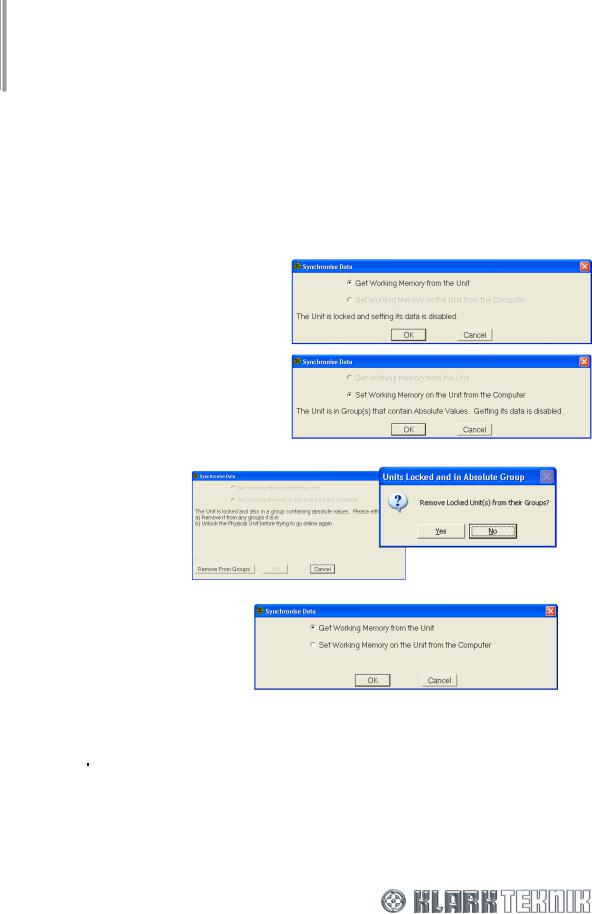
Important!
We recommend that you always save your show file settings before going option of reverting to previous settings after a Get Working Memory from the Unit entire system online
online, so that you have the synchronisation. To set the
1 Click on  (towards the bottom left-hand side of the screen).
If a unit is locked, it is not possible to write to that unit and therefore the Set All function will be disabled. It is possible to read memory from that unit even if is locked.
If a unit is unlocked but that unit is in any group that contains an absolute value, it is not possible to read data from that unit as it would affect other channels
If a physical unit is locked and the RCS unit is in an absolute group it is not possible to go online at all. There are two choices, either remove that unit from the group or physically turn the locking off at the unit. Selecting the Remove From Groups option causes a confirmation window to appear.
Where there are no locking or grouping issues, this window will appear.
2 |
At the Synchronise Data window, choose to Get Working Memory from the Unit to upload settings |
||
|
from the units to overwrite the current PC settings in the respective Add-In Devices or Set |
||
|
Working Memory on the Unit from the Computer to download the PC settings to the units, as required. |
||
|
Click |
OK |
to continue. |
To take the entire system offline
Click on  (towards the bottom right-hand side of the screen) to take the entire system offline. The online/offline status boxes on the unit bars in FastNav® (DN9848 Units Home screen) will update accordingly.
29
HELIX DN9848E Remote Control Software
User Guide
To set a particular unit online
1Go to the DN9848 Units Home screen and select the respective HELIX DN9848E unit by clicking on its unit bar in FastNav®.
2Click  (see diagram right).
3At the Synchronise Date window, choose to download the PC settings to the Unit (Set Working Memory on the Unit from the Computer), or upload settings from the Unit to overwrite the current PC settings in the respective Add-In Devices (Get Working Memory from the Unit).
4Click OK .
.
When contact is successfully established, the  (red) button changes to
  (green) and the online status bar on the unit bar (see section 3.3.1) also changes to green, while at the HELIX unit the alphanumeric shows T/R activity. If the connection is not immediate the button changes to
 (yellow) while it tries to establish wireless contact.
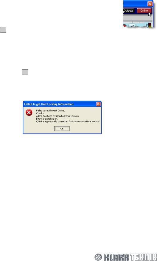
If online contact cannot be established, an error message is returned (immediately below). This must
be acknowledged by pressing OK . Thereafter, HELIX DN9848E RCS will continue polling the unit unless
taken Offline. Continuous polling is primarily designed to facilitate wireless communication, where the link may briefly disappear, for example, when you walk behind an obstructing object. However, it can also be useful when fault finding cabled communication, as the button will turn green as soon as the problem is corrected.
Caution!
Changes should not be made to equalisation settings at the unit while the HELIX DN9848E RCS is attempting to establish communication, as the unit and Add-In may lose synchronisation.
To take a unit offline
1Go to the DN9848 Units Home screen and select the respective HELIX DN9848E unit by clicking on it unit bar in FastNav®.
2Click on  (green).
To check the online status of the units in the system
Go to the DN9848E Units Home screen and check the activity of the online status indicator on the unit bars; see section 3.3.1.
30
 Loading...