


DN6000 User Manual
CONTENTS: |
|
INTRODUCTION |
2 |
INSTRUMENT FAMILIARISATION |
3 |
FREQUENCY ANALYSYS MODE |
7 |
MEMORY RECALL MODE |
9 |
UTILITIES IN FREQUENCY ANALYSIS MODE |
10 |
TIME ANALYSYS MODE |
15 |
UTILITIES IN TIME ANALYSIS MODE |
18 |
TECHNICAL SPECIFICATION |
23 |
Introduction
Thank you for using this Klark-Teknik Product
To obtain maximum performance from this precision electronic product, please study these instructions carefully. Installation and operating the DN6000 is not complicated, but the flexibility provided by it’s operating features merits familiarisation with it’s controls and connections. This unit has been prepared to comply with the power supply requirements that exist in your location.
Precautions
Do not install this unit in a location subjected to excessive heat, dust or mechanical vibrations.
Power Connection
Connection is made by means of an IEC standard power socket. The rear panel voltage label indicates the voltage required for satisfactory operation of the unit. Before connecting this unit to the mains supply, ensure the fuse fitted is the correct type and rating, as indicated on the rear panel, adjacent to the fuse holder.
Safety Warning
This unit is fitted with 3-pin power socket: For safety reasons the earth lead should not be disconnected. To prevent shock or fire hazard, do not expose the unit to rain or moisture. To avoid electrical shock do not remove covers. Refer servicing to qualified personnel only.
After you have unpacked the unit Save all the packing materials - they will prove valuable should it become necessary to transport or ship this product.
Please inspect this unit carefully for any signs of damage incurred during transportation. It has undergone stringent quality control inspection and tests prior to packing and left the factory in perfect condition
If, however, the unit shows any signs of damage, notify the transportation company without delay. Only you, the consignee, may institute a claim against the carrier for damage during transportation.
If necessary, contact your supplier or as a last resort, your Klark-Teknik importing agent*,
who will fully co-operate under such circumstances.
2

INSTRUMENT FAMILIARISATION
Front View
Rear View
Display
The LCD display features a large graphics area, flanked by titles for the 4 menu switches at the right hand end, and measurement information in a Status Column at the left hand end.
Numeric display
The 3 x 7 segment LED Numerical display gives a constantly updated read out of the level at the cursor position, visible at a distance.
3
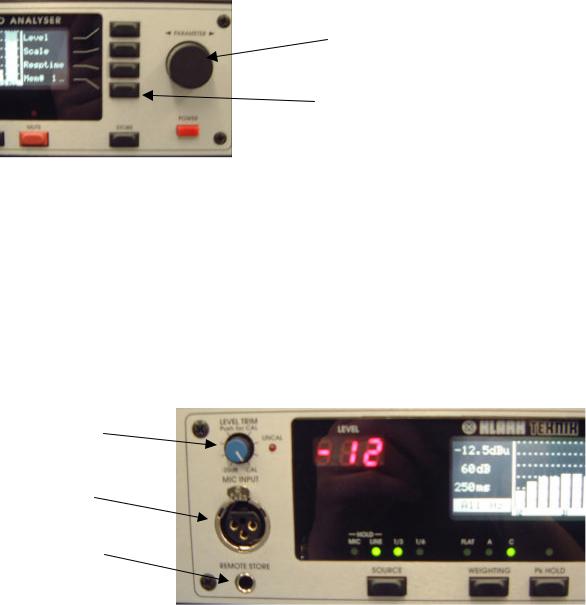
Menu switches
Rotary Encoder
Menu
Switches
Four menu switches allow instant selection of various functions, depending on the mode of the analyser.
Rotary Encoder
A single rotary encoder allows continuous adjustment of any selected function or measurement parameter. When nothing is selected, the encoder controls the movement of a cursor across the graphic area of the display. The Numerical display gives a constant read out of the level at the cursor position. With peak hold active, the level of the held peak is given. With peak hold inactive, the level of the column is given. The lowest line of the status column shows the frequency or time interval at the cursor position.
Level Trim
Mic XLR
Store Socket
Mic XLR:
The input signal from a microphone is accepted on a standard XLR socket on the front panel. The DN6000 has a 48v phantom supply. The mic input sensitivity can be adjusted internally to calibrate the unit for a particular Klark Teknik 6051 microphone or the recommended Bruel & Kjaer model 4006. This adjustment requires the use of a specialised microphone calibrator and should only be carried out by qualified, authorised service personnel.
Level Trim:
Input level trim control giving 20 dB of attenuation on the mic or line input signal. Push the knob to activate or deactivate the control. The red ‘Un-calibrated’ LED lights when the trim control is activated.
4
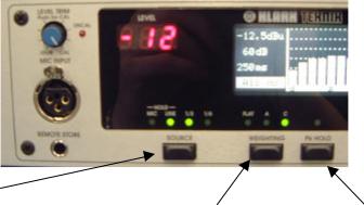
Store Socket:
This jack socket is wired in parallel with the ‘Store’ switch. When used with a suitable cable and switch assembly the store operations can be performed from the microphone position. The switch should be a momentary type; normally open.
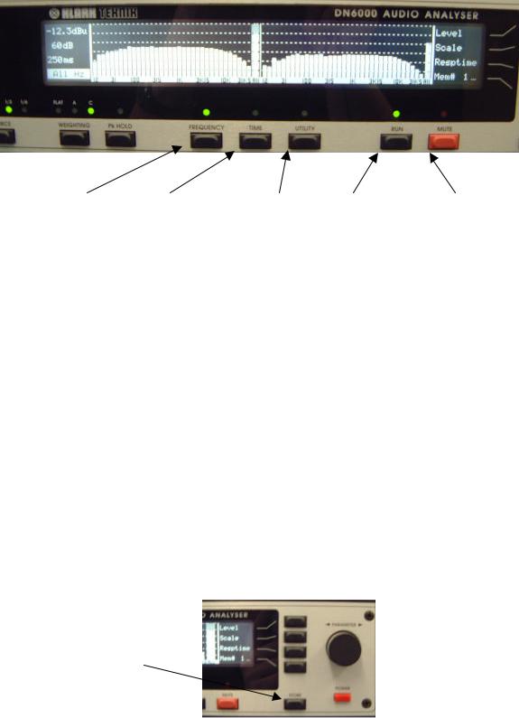
Source Switch
Weighting Switch |
Peak Hold |
Source Switch:
Press and hold the source switch to switch between microphone input (front panel) and line inputs (rear panel). For line inputs, all measurements are in dBu, where 0dBu = 0.775 volts. For microphone input, all measurements are in dB SPL (Sound Pressure Level) where 0dB SPL = 2 x 10⁻⁵ N/m2.
In Frequency analysis mode, with mic input selected, a single press toggles between 1/3 Octave and 1/6 octave spectrum analysis. With line inputs selected, single presses switch between stereo 1/3 octave, mono 1/3 octave and mono 1/6 octave spectrum analysis.
Weighting Switch:
Successive presses of the weighting switch cycle the unit through 3 input filter options: A weighting, C weighting and un-weighted.
Peak Hold:
Pressing the peak hold switch activates or deactivates the peak hold function. When peak hold is active, horizontal marks on the display show the highest level reached by each column. The peaks are held in memory when peak hold is deactivated. To clear the held peaks, press and hold the peak hold switch for 3 seconds.
5
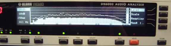
Frequency |
Time |
Utility |
Run |
Mute |
Frequency Switch:
Press to select frequency mode. In this mode, the graphic area of the display shows a graph of level against frequency. This allows for conventional spectrum analysis and continuous monitoring of signal level in dB SPL (sound pressure level) or dBu.
Time Switch:
Press to select time mode. In this mode the graphic area of the display shows a graph of level against time. This allows for measurement of RT60 (reverberation time), delay time, Leq (equivalent sound pressure level) and Let (equivalent sound dose).
Utilities Switch:
Pressing this switch calls up a utilities menu in either Frequency or Time modes. Press the switch again to exit the utilities menu.
Run switch:
Press the run switch to activate or deactivate a measurement. Active run status is indicated by a green LED.
Mute switch:
Press this switch to mute or un-mute the test signal output. A muted output is indicated by the red LED.
Store
Switch
Store Switch:
Press the store switch to store the current measurement on the display to the currently addressed memory. The new measurement may be accumulated to the addressed memory or may overwrite it and increment the address. See memory sub menu for details.
6
Frequency Analysis Mode:
These functions are available in frequency analysis mode. To enter frequency analysis mode, press the ‘Frequency’ switch.
1.Press the ‘Level’ switch to select the input reference level for adjustment. Adjust the reference level with the rotary encoder. The current input reference level is shown at the top of the status column. The input level can rise 12 dB above the top of the display without clipping the A to D converter.
Options are:
dBu |
dB SPL |
|
40 |
140 |
|
30 |
130 |
Note: Clipping of the input circuit at any frequency |
20 |
120 |
affects measurements at all other frequencies, and |
10 |
110 |
hence is indicated by a large on-screen warning. |
0 |
100 |
|
-10 |
90 |
|
-20 |
80 |
|
-30 |
70 |
|
-40 |
60 |
|
-50 |
50 |
|
2.Press the ‘Scale’ switch to select the display scale for adjustment. Adjustment the display scale with the rotary encoder. The current display scale (the distance in dB between the top and bottom of the graphic display) is shown on the second line of the status column. Options are:
60dB |
|
30dB |
Note: On the 6dB scale, the display has a resolution |
20dB |
of 10 pixels per dB. The accuracy of the analyser, |
15dB |
however, is still restricted to +/-0.3 dB. |
10dB |
|
6dB |
|
7
 Loading...