

Page 1

CONTENTS:
INTRODUCTION 2
INSTRUMENT FAMILIARISATION 3
FREQUENCY ANALYSYS MODE 7
MEMORY RECALL MODE 9
UTILITIES IN FREQUENCY ANALYSIS MODE 10
TIME ANALYSYS MODE 15
UTILITIES IN TIME ANALYSIS MODE 18
TECHNICAL SPECIFICATION 23
DN6000 User Manual
Page 2

Introduction
Thank you for using this Klark-Teknik Product
To obtain maximum performance from this precision electronic product, please study
these instructions carefully. Installation and operating the DN6000 is not complicated,
but the flexibility provided by it’s operating features merits familiarisation with it’s
controls and connections. This unit has been prepared to comply with the power
supply requirements that exist in your location.
Precautions
Do not install this unit in a location subjected to excessive heat, dust or mechanical
vibrations.
Power Connection
Connection is made by means of an IEC standard power socket. The rear panel
voltage label indicates the voltage required for satisfactory operation of the unit.
Before connecting this unit to the mains supply, ensure the fuse fitted is the correct
type and rating, as indicated on the rear panel, adjacent to the fuse holder.
Safety Warning
This unit is fitted with 3-pin power socket: For safety reasons the earth lead should not
be disconnected. To prevent shock or fire hazard, do not expose the unit to rain or
moisture. To avoid electrical shock do not remove covers. Refer servicing to qualified
personnel only.
After you have unpacked the unit Save all the packing materials - they will prove
valuable should it become necessary to transport or ship this product.
Please inspect this unit carefully for any signs of damage incurred during
transportation. It has undergone stringent quality control inspection and tests prior to
packing and left the factory in perfect condition
If, however, the unit shows any signs of damage, notify the transportation company
without delay. Only you, the consignee, may institute a claim against the carrier for
damage during transportation.
If necessary, contact your supplier or as a last resort, your Klark-Teknik importing
agent*,
who will fully co-operate under such circumstances.
2
Page 3
INSTRUMENT FAMILIARISATION
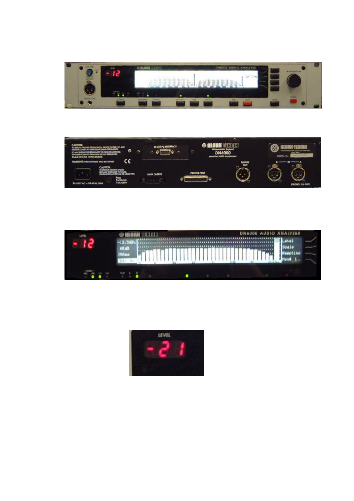
Front View
Rear View
Display
The LCD display features a large graphics area, flanked by titles for the 4 menu
switches at the right hand end, and measurement information in a Status Column at the
left hand end.
Numeric display
The 3 x 7 segment LED Numerical display gives a constantly updated read out of the
level at the cursor position, visible at a distance.
3
Page 4
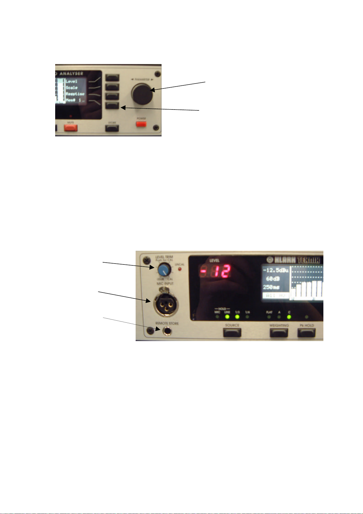
Menu switches
Four menu switches allow instant selection of various functions, depending on the
mode of the analyser.
Rotary Encoder
A single rotary encoder allows continuous adjustment of any selected function or
measurement parameter. When nothing is selected, the encoder controls the
movement of a cursor across the graphic area of the display. The Numerical display
gives a constant read out of the level at the cursor position. With peak hold active, the
level of the held peak is given. With peak hold inactive, the level of the column is
given. The lowest line of the status column shows the frequency or time interval at the
cursor position.
Level Trim
Mic XLR
Store Socket
Mic XLR:
The input signal from a microphone is accepted on a standard XLR socket on the front
panel. The DN6000 has a 48v phantom supply. The mic input sensitivity can be
adjusted internally to calibrate the unit for a particular Klark Teknik 6051 microphone
or the recommended Bruel & Kjaer model 4006. This adjustment requires the use of a
specialised microphone calibrator and should only be carried out by qualified,
authorised service personnel.
Level Trim:
Input level trim control giving 20 dB of attenuation on the mic or line input signal.
Push the knob to activate or deactivate the control. The red ‘Un-calibrated’ LED
lights when the trim control is activated.
Rotary Encoder
Menu
Switches
4
Page 5
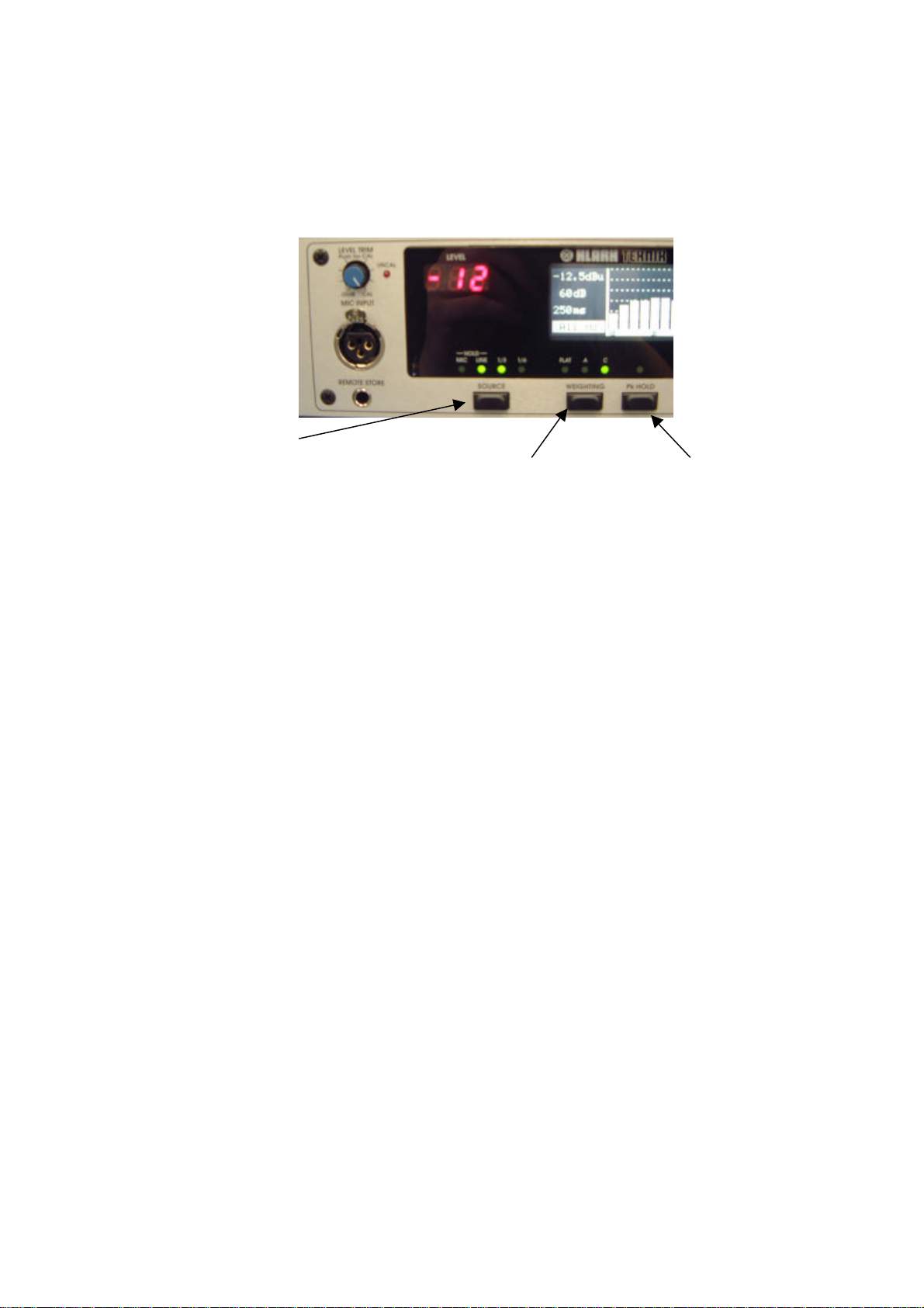
Weighting Switch
Store Socket:
This jack socket is wired in parallel with the ‘Store’ switch. When used with a suitable
cable and switch assembly the store operations can be performed from the microphone
position. The switch should be a momentary type; normally open.
Source Switch
Source Switch:
Press and hold the source switch to switch between microphone input (front panel)
and line inputs (rear panel). For line inputs, all measurements are in dBu, where 0dBu
= 0.775 volts. For microphone input, all measurements are in dB SPL (Sound
Pressure Level) where 0dB SPL = 2 x 10⁻⁵ N/m2.
In Frequency analysis mode, with mic input selected, a single press toggles between
1/3 Octave and 1/6 octave spectrum analysis. With line inputs selected, single presses
switch between stereo 1/3 octave, mono 1/3 octave and mono 1/6 octave spectrum
analysis.
Weighting Switch:
Successive presses of the weighting switch cycle the unit through 3 input filter
options: A weighting, C weighting and un-weighted.
Peak Hold:
Pressing the peak hold switch activates or deactivates the peak hold function. When
peak hold is active, horizontal marks on the display show the highest level reached by
each column. The peaks are held in memory when peak hold is deactivated. To clear
the held peaks, press and hold the peak hold switch for 3 seconds.
5
Page 6
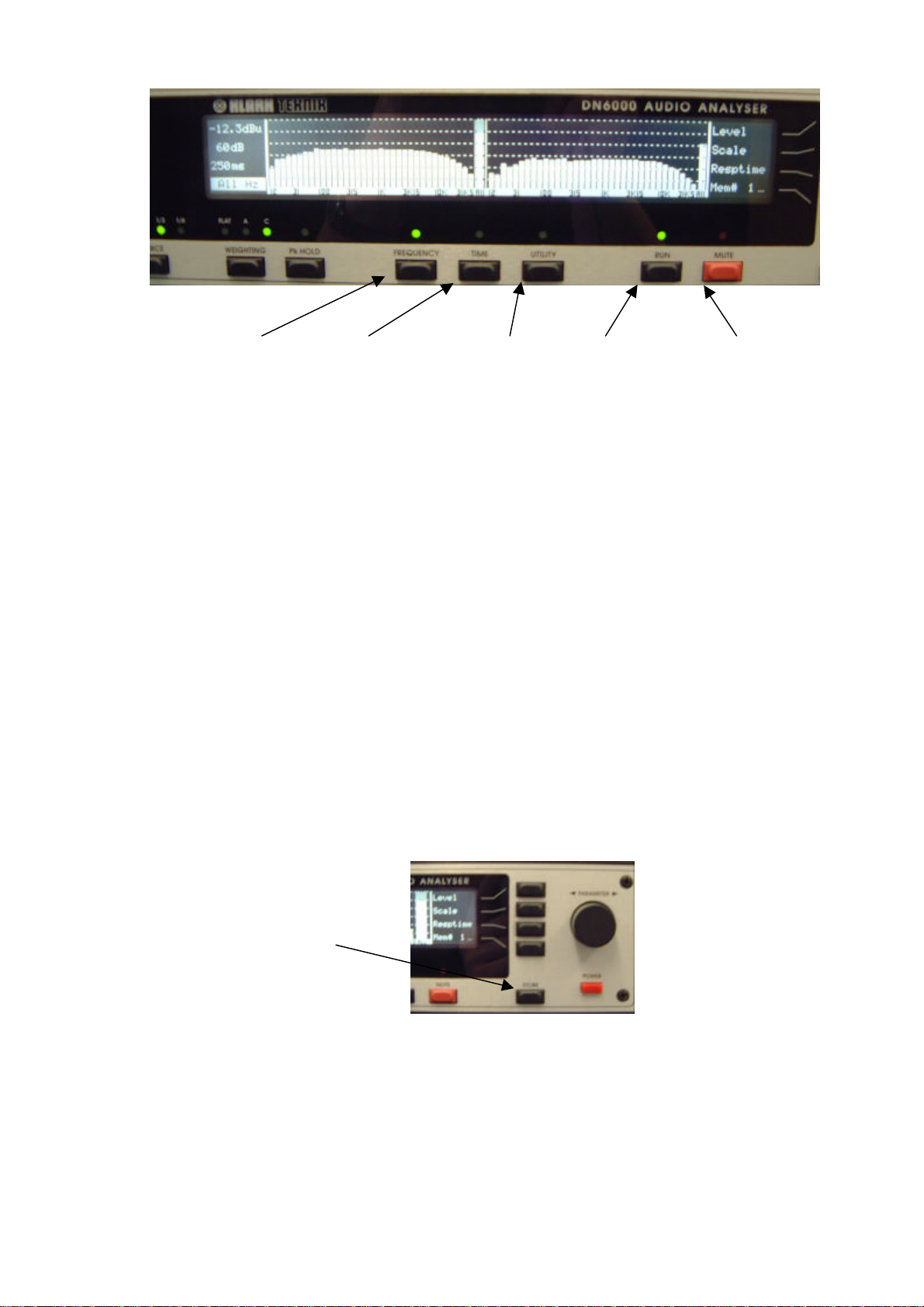
Switch
Frequency Time Utility
Frequency Switch:
Press to select frequency mode. In this mode, the graphic area of the display shows a
graph of level against frequency. This allows for conventional spectrum analysis and
continuous monitoring of signal level in dB SPL (sound pressure level) or dBu.
Time Switch:
Press to select time mode. In this mode the graphic area of the display shows a graph
of level against time. This allows for measurement of RT60 (reverberation time), delay
time, Leq (equivalent sound pressure level) and Let (equivalent sound dose).
Utilities Switch:
Pressing this switch calls up a utilities menu in either Frequency or Time modes. Press
the switch again to exit the utilities menu.
Run switch:
Press the run switch to activate or deactivate a measurement. Active run status is
indicated by a green LED.
Mute switch:
Press this switch to mute or un-mute the test signal output. A muted output is
indicated by the red LED.
Store Switch:
Press the store switch to store the current measurement on the display to the currently
addressed memory. The new measurement may be accumulated to the addressed
memory or may overwrite it and increment the address. See memory sub menu for
details.
Store
Mute
6
Page 7

Frequency Analysis Mode:
These functions are available in frequency analysis mode. To enter frequency analysis
mode, press the ‘Frequency’ switch.
1. Press the ‘Level’ switch to select the input reference level for adjustment. Adjust
the reference level with the rotary encoder. The current input reference level is
shown at the top of the status column. The input level can rise 12 dB above the top
of the display without clipping the A to D converter.
Options are:
dBu dB SPL
40 140
30 130 Note: Clipping of the input circuit at any frequency
20 120 affects measurements at all other frequencies, and
10 110 hence is indicated by a large on-screen warning.
0 100
-10 90
-20 80
-30 70
-40 60
-50 50
2. Press the ‘Scale’ switch to select the display scale for adjustment. Adjustment the
display scale with the rotary encoder. The current display scale (the distance in dB
between the top and bottom of the graphic display) is shown on the second line of
the status column. Options are:
60dB
30dB Note: On the 6dB scale, the display has a resolution
20dB of 10 pixels per dB. The accuracy of the analyser,
15dB however, is still restricted to +/-0.3 dB.
10dB
6dB
7
Page 8

3. Press the ‘Resp. Time’ switch to select the response time of the display for
adjustment. Adjust the response time with the rotary encoder. The current
response time (the duration of measurement, and hence the duration of each column
before it is updated) is shown on the third line of the status column. Options are:
10 mS
35 mS (I) IEC 651 “Impulse” response
125 mS (F) IEC 651 “Fast” response
250 mS
1 S (S) IEC 651 “Slow” response
2 S
5 S
10 S
20 S
Note: The height of each column on the display indicates the Average or Peak level
measured over the previous response time period.
8
Page 9

Memory Recall Mode:
Press the ‘Memory’ switch to enter the memory sub menu.
The memory sub-menu options are:
Recall
Compare
Over / Ac00
Exit
Use the rotary encoder to scroll through the memory addresses. The contents of the
addressed memory are displayed on the graphic area.
Press the ‘Recall’ switch to recall the addressed memory to the main display. The
cursor can then be used to examine the measurement data in detail. The view can also
be adjusted via the Level and Scale controls.
Press the ‘Compare’ switch to recall the addressed memory to the main screen
interleaved
again to clear the compare function.
Press the ‘Over / Ac’ to switch each memory between Accumulate and Overwrite
modes. When Store is pressed in Accumulate mode, the new measurement data is
averaged with the existing data in the memory. A true average of all the accumulated
data is calculated. The number next to ‘Ac’ shows the total number of accumulations
in the current memory position. When Store is pressed in Overwrite mode, the new
data overwrites any old data in the memory, and the memory address is increased by
one.
Press ‘Exit’ to return to the main display and main menu.
with the current measurement, whether run is on or off. Press ‘Memory’
9
Page 10

Utilities In Frequency Analysis Mode:
The Frequency Utilities menu is called up by pressing the Utilities switch while in
Frequency mode. Frequency Utilities options are:
Press ‘Output’ to access the Output sub menu and set up the output test signal.
Press ‘Display’ to access the display sub menu and set up the LCD display. See
below.
Press ‘Print’ to access the Print sub menu and create a print out. See below.
Output Signal Sub Menu:
By pressing ‘Output’ while in the Frequency Utilities menu the output sub menu may
be accessed. The options are:
Press ‘Sine...’ to select a sine wave test signal and to call up the Sine sub menu.
Press ‘Noise...’ to select a pink noise test signal and to call up the pink noise sub menu.
Press ‘Sweep...’ to call up the sweep sub menu to configure and trigger a frequency
sweep.
4. Press ‘Exit’ to return to the Frequency Utilities menu.
10
Page 11

Sine Wave Sub Menu:
The Sine wave sub menu is called up by pressing the ‘Sine...’ switch in the Output sub
menu. Sine sub menu options are:
Press ‘Frequency’ to select the sine wave frequency for adjustment. Adjust the
frequency with the rotary encoder. Frequency of the test signal is shown in the status
column.
Press ‘Level’ to select the test signal output level for adjustment. Adjust the output
level with the rotary encoder. Output level is shown in the status column, and has a
range of -40 to +4 dBu.
Press ‘Gate Time’ to set the gate time of the test signal. Adjust the gate time with the
rotary encoder. Gate time is shown in the status column. When Gate time is set to
Cont., the test signal output is under manual control. It can be switched off and on by
use of the Mute switch. When gate time is set to anything other than Cont. The
normal state of the unit is muted. When the mute switch is pressed, the test signal is
present for the set gate time, after which it is muted again. Options are:
100 mS
200 mS
500 mS
1 S
2 S
5 S
10 S
Cont
Note: Sine wave bursts always start and stop on a zero crossing. The gate time setting
is therefore less accurate for low frequency settings.
Press ‘Exit’ to return to the Utilities menu.
11
Page 12

Noise Sub Menu:
The Noise sub menu is called up by pressing the ‘Noise...’ switch in the Output sub
menu. Noise sub menu options are:
Press ‘Filter’ to cycle through the bandwidth options for the pink noise output. These
options are full bandwidth, 1 octave bandwidth and 1/3 octave band width. Adjust the
centre frequency of the filter with the rotary encoder. The bandwidth and Frequency
of the test signal are shown in the status column.
Press ‘Level’ to select the test signal output level for adjustment. Adjust the output
level with the rotary encoder. Output level is shown in the status column, and has a
range of -40 to +4dBu.
Press ‘Gate Time’ to set the gate time of the test signal. Adjust the gate time with the
rotary encoder. Gate time is shown in the status column. When Gate time is set to
Cont., the test signal output is under manual control. It can be switched off and on by
use of the Mute switch. When gate time is set to anything other than Cont. The
normal state of the unit is muted. When the mute switch is pressed, the test signal is
present for the set gate time, after which it is muted again. Options are:
100 mS
200 mS
500 mS
1 S
2 S
5 S
10 S
Cont
Press ‘Exit’ to return to the Utilities menu.
12
Page 13

Sweep Sub Menu:
The Sweep sub menu is called up by pressing the ‘Sweep...’ switch in the Output sub
menu. Options are:
Press ‘Start f’ to select the start frequency of the sweep for adjustment. Adjust start
frequency with the rotary encoder. The frequency is shown in the status column.
Press ‘Stop f’ to select the stop frequency of the sweep for adjustment. Adjust stop
frequency with the rotary encoder. The frequency is shown in the status column.
Press ‘Level’ to select the sweep signal output level for adjustment. Adjust the output
level with the rotary encoder. Output level is shown in the status column, and has a
range of -40 to +4dBu.
Press the ‘Run’ switch while in the Sweep sub menu to initiate a frequency sweep.
The test signal will sweep between the set start and stop frequencies at a rate
dependant on the Response Time set for the main display. ‘Run’ will switch off at the
end of the sweep, so that the frequency spectrum captured during the sweep is frozen
on the display. As the start and stop frequencies can be set anywhere in relation to
each other, the sweep can move up or down the frequency range.
Press ‘Exit’ to return to the Utilities menu.
13
Page 14

Display sub menu:
The ‘Display’ sub menu is called up by pressing the display switch in the Frequency
Utilities menu. Options are:
Press ‘Ave Peak’ to select average or peak response. When set to average response,
the spectrum analyser columns represent the average signal level at that frequency over
the previous response time interval. When set to peak response, the spectrum analyser
columns represent the peak or maximum signal level at that frequency over the
previous response time interval.
Press ‘Sum / Diff’ to cycle through the three options for dual channel and memory
compare display. With neither Sum nor Diff selected, the graphic area shows the two
channels side by side. With Sum selected, the graphic area shows the sum (A+B) of
the two channels. With Diff selected, the graphic area shows the difference of the two
channels (A-B).
Press ‘LCD...’ to select the LCD sub menu for adjustment. See below.
Press ‘Exit’ to return to the Utilities menu.
14
Page 15

Time Analysis Mode
To enter time analysis mode, press the ‘Time’ switch. The graphic display shows a
graph of level against time for the most recent measurement in the form of 180
columns. The period of time represented by each column, and hence the total time
represented by the graph, may be set in the Time Utilities menu.
Time analysis mode is fundamentally different from frequency analysis. This mode is
designed for single, one shot measurements.
Before a measurement is taken, set up the Level and Scale in frequency analysis mode.
Set up filter, time and trigger parameters in the Time Utilities menu.
Set the weighting option as required, e.g. A weighting for LAeq analysis.
Initiate a measurement by pressing the ‘Run’ switch (LED comes on). It may take
from several milliseconds to over a week to complete a measurement, dependant on
the Time parameter setting. A measurement may be interrupted at any time by
pressing the ‘Run’ switch (LED goes off).
After the measurement is completed (or stopped), the data may be stored in a memory
by pressing the ‘Store’ switch. The displayed data may be output to a printer (via the
Global Utilities menu) or inspected and post processed by use of the cursor function
and the menu switches.
In time analysis mode, the graphic area of the LCD display shows a graph of level
against time. The status column at the left hand end of the display shows information
relating to the graph, including the time interval corresponding to the cursor position.
The menu at the right hand end of the display gives options of RT60, Leq and Let
analysis. The Numerical display gives RT60, Delay, Leq or Let at the cursor position,
as selected by the menu switches. With no menu switch selected, the Numerical
display gives the average (peak hold off) or peak (peak hold on) signal level at the
cursor position.
Note: RT60 measurement is inhibited for measurement times greater than 30 seconds.
Press the ‘RT60’ switch to select RT60 analysis of the measurement data.
Note 1:RT60 is a standard measurement of reverberation time. It is the time taken for
a signal to fall 60dB SPL in level. Any section of the measurement graph can be
selected and analysed to give an RT60. This allows the user to avoid early reflection
non-linearity’s and the ambient noise floor.
15
Page 16

Use the cursor to select the left hand end of the section to be analysed
RT60. Select RT60 analysis by pressing the ‘RT60’ switch. Now use the rotary
encoder to extend the section to the right. The RT60, shown on the Numerical
display, will be constantly recalculated for the selected section.
Note 2:RT60 measurement is inhibited for measurement times greater than 30 seconds.
Press the ‘Leq’ switch to select Leq (Equivalent Continuous Sound Pressure Level)
analysis. Use the rotary encoder to select a column in the graphic display. The last
line of the status column shows the time from the start of the measurement to the
selected column. The Numerical display shows the Leq for the time interval of the
selected column. While Leq is selected, a table of all Leq values for all columns can be
printed via the Global utilities, ‘print’ sub menu.
5. Press the ‘Let’ switch to select Let (Sound Exposure Level) analysis. Use the
rotary encoder to select a column in the graphic display. The last line of the status
column shows the time from the start of the measurement to the selected column.
The Numerical display shows the Let fo r the time interval from the start of the
measurement to the end of the selected column. While Let is selected, a table of all
Let values for all columns can be printed via the Global utilities, ‘print’ sub menu.
before
selecting
16
Page 17

Press the ‘Memory’ switch to enter the memory sub menu.
Options are:
Use the rotary encoder to scroll through the memory addresses. The contents of the
addressed memory are displayed on the graphic area.
Press the ‘Recall’ switch to recall the addressed memory to the main display. The
cursor can then be used to examine the measurement data in detail.
Press the ‘Over / Ac’ to switch each memory between Accumulate and Overwrite
modes. When Store is pressed in Accumulate mode, the new measurement data is
averaged with the existing data in the memory. A true average of all the accumulated
data is calculated. The number next to ‘Ac’ shows the total number of accumulations
in the current memory position. When Store is pressed in Overwrite mode, the new
data overwrites any old data in the memory, and the memory address is increased by
one.
Press ‘Exit’ to return to the main display and main menu.
17
Page 18

Utilities in the Time Analysis Mode
The Time mode pressing the Utilities switch while in Time mode will bring up the
following menu.
Press ‘Param...’ to select the Parameters sub menu and set up the various
measurement parameters.
Press ‘LCD...’ to select the LCD sub menu for adjustment of Contrast, Brightness and
to invert the display colours (black on white to white on black).
Press ‘Print...’ to access the Print sub menu and create a print out.
Press ‘Exit’ to return to the main display menu.
18
Page 19

Parameters Sub Menu
The Parameters sub menu is accessed by pressing ‘Param...’ in the Time Utilities
menu. Options are:
Press ‘Filter’ to cycle through the input filter options (1/3 octave, 1 octave, full
bandwidth) and to select filter centre frequency for adjustment. Use the rotary encoder
to adjust centre frequency. The filter type and frequency are shown on the first line of
the status column.
Note: The filter is on the input. The test signal is always full bandwidth pink noise.
Press ‘Time’ to select the total duration of the measurement for adjustment. Adjust
the measurement time with the rotary encoder. Measurement Time is shown on the
second line of the status column. The time of the measurement is 180 x time for each
column, as there are a maximum of 180 columns. Options are:
Column Time
0.2 mS 40mS
0.5 mS 90 mS
1 mS 180 mS
5 mS 900 mS
10 mS 1.8 S
50 mS 9 S
100 mS 18 S
200 mS 36 S RT60 calculation inhibited if length > 30 seconds
500 mS 1.5 minute
1 S 3 mins
5 S 15 mins
10 S 30 mins
1 min 3 hours
5 mins 15 hrs
15 mins 45 hrs
30 mins 90 hrs
1 hr 180 Hrs
19
Page 20

Press ‘Trigger’ to switch between internal and external triggering of the measurement.
Internal: When the measurement is initiated by pressing ‘Run’, the test signal output
is muted and the measurement begins immediately. This method is recommended for
system delay measurements as well as for Leq and Let analysis.
External: When the measurement is initiated by pressing the ‘Run’ switch, the test
signal output is muted immediately. The DN6000 waits for an overlo ad condition to
occur. When the overload condition ends, the measurement begins. This method is
recommended for RT60 measurements using either the internal test signal (amplified)
or a starter pistol or clapper to provide the initial acoustic impulse. The method will be
familiar to users of the Klark Teknik model RT60 reverberation time analyser.
Press ‘Exit’ to return to the main display and main menu.
20
Page 21

LCD Sub Menu:
Press ‘Contrast’ to select the LCD display contrast for adjustment. Adjust the
contrast with the rotary encoder.
Press ‘Brightn.’ to select the LCD brightness for adjustment. Adjust the LCD
brightness with the rotary encoder.
Press ‘Invert’ to reverse the LCD colours; from black on white to white on black and
vice versa.
Press ‘Exit’ to return from the LCD sub menu.
21
Page 22

Print sub menu
The print sub menu is called up by pressing the ‘Print’ switch in the Global Utilities
menu. It allows data to be sent to an external printer connected to the Centronics
compatible printer port. The attached printer must be Epson compatible, or configured
to emulate an Epson printer. The options are:
Press ‘Graph’ to print out the graph as shown on the LCD display, together with the
status and cursor information.
Press ‘Table’ to print out a table of the numerical data represented on the LCD
display.
Press ‘Exit’ to return from the Print sub menu without initiating a print out.
Note: There is also PC software package that will allow the unit to be linked to a PC
and screen shots and tables to be stored electronically. This requires an RS2323
port to be retrofitted to the unit. (This was fitted as standard on units supplied after
the 1st March 2002). Information is available on request.
22
Page 23

TECHNICAL SPECIFICATION
Frequency Response 5Hz to 40kHz
Microphone Input Differential .25mV/uBar to1mV/uBar
Sensitivity 140dBspl to 50dBspl
Powering 48V dc phantom power (nominal)
Connector XLR on front panel
Line Input Two, Differential - balanced or unbalanced
Sensitivity 40dBu to -50dBmin
Impedance 47k ohm
Connector XLRs on rear panel
Attenuation accuracy +-0.1dB
'A'-weighting Selectable to IEC 651 type 1 requirement
'C'-weighting Selectable to IEC 651 type 1 requirement
Pink Noise output Digital pseudo-random white noise generator
with pink noise filter
Frequency distribution -3dB/Octave 20Hz to 20kHz +_0.2dB
Level +4dBu, -10dBu, -30dBu
Impedance 50 ohms balanced
Connector XLR on rear panel
Interfaces DN3600, parallel printer, Open Architecture
Port
Power requirements
Voltage 100 to 240, 50 to 60Hz
Consumption Less than 40VA
Weight
Net
Shipping Dimensions
Width 482mm
Depth
Height 89mm
Optional 6051 Microphone
Frequency Response Flat to 15KHz
Sensitivity 0.5mV per uBar nominal @ 1kHz
Dynamic range 20 to 130dBspl
Capsule 0.25 inch electret condenser
Type pressure - omni directional
Power required 14V Phantom power
23
 Loading...