

Page 1

DN360
OPERATORS MANUAL
Klark Teknik Group,
Klark Teknik Building,
Walter Nash Road,
Kidderminster.
Worcestershire.
DY11 7HJ.
England.
Tel:+44 1562 741515
Fax:+44 1562 745371
Email: sales@ktgplc.com
Website: www.klarkteknik.com
Page 2
Walter Nash Road, Kiddermi nster, Worces te rs hire. DY11 7HJ. England
Tel: (44) (0) 1562 741515. Fax: (44) (0) 1562 745371
Company Registratio n No: 2414018
abc d abc
SIGNAL P ROCESSING BY D EFINITION BETTERBY DESIGN DESIGNEDFOR APUREPERFORMANCE
DECLARATION OF CONFORMITY
We,
Klark Teknik Group (UK) Plc
of, Klark Teknik Building, Walter Nash Road, Kidderminster, Worcestershire, DY11 7HJ
Declare that a sample of the following product:-
Product Type Number Product Description Nominal Voltage (s) Current Freq
DN360 Graphic Equaliser 115V AC 60mA 50/60Hz
230V AC 120mA
to which this declaration refers, is in conformity with the following directives and/or standards:-
Directive(s) Test Standard(s)
Low voltage Directive 73/23/EEC EN 60065
EMC 89/336/EEC amended by 92/31/EEC & 93/68/EEC EN 50081-1 : 1992
EMC 89/336/EEC amended by 92/31/EEC & 93/68/EEC EN 55022 Class B
EMC 89/336/EEC amended by 92/31/EEC & 93/68/EEC EN 50082-1 : 1994
EMC 89/336/EEC amended by 92/31/EEC & 93/68/EEC ENV 50140/ 8-93
EMC 89/336/EEC amended by 92/31/EEC & 93/68/EEC ENV 50140/ 2-95
EMC 89/336/EEC amended by 92/31/EEC & 93/68/EEC EN 5014 1 : 1993
EMC 89/336/EEC amended by 92/31/EEC & 93/68/EEC EN 60801-2 : 1993
Signed:............................
Name: F. D. Merrey Jnr
UL 813
CSA 22.2 No1 M90
IEC 801-4/88
Date: 27th August, 1999
Authority: Managing Director, Klark Teknik Group (UK) Plc
Attention!
Where applicable, the attention of the specifier, purchaser, installer or user is drawn to special limitations of use
which must be observed when these products are taken into service to maintain compliance with the above
directives. Details of these special measures and limitations to use are available on request and are available
in product manuals.
A Subsidiary of Telex communications, Inc.
Page 3

THANK YOU FOR USING THIS KLARK TEKNIK PRODUCT
To obtain maximum performance from this precision electronic product, please study these instructions carefully.
Installation and operating the equaliser is not complicated, but the flexibility provided by its operating features
merits familiarisation with its controls and connections. This unit has been prepared to comply with the power
supply requirements that exist in your location.
Precautions
Before connecting the unit to the mains power, ensure that the operating voltage is correct for your local supply.
It is important that you observe the following instructions if another voltage setting is required.
Do not install this unit in a location subjected to excessive heat, dust or mechanical vibrations.
Voltage Selection and Power Connection
Connection is made by means of an IEC standard power socket. The rear panel voltage label, indicates the
voltage required for satisfactory operation of the unit.
Before connecting this unit to the mains supply, ensure the fuse fitted is the correct type and rating is as
indicated on the rear panel, adjacent to the fuse holder.
*Mains voltage change should be carried out by a qualified service technician only.
Safety Warning
This unit is fitted with 3-pin power socket: For safety reasons the earth lead should not be disconnected.
Signal 0V is referenced internally to chassis via a resistor capacitor network which provides earth loop immunity.
To prevent shock or fire hazard, do not expose the unit to rain or moisture. To avoid electrical shock do not
remove covers. Refer servicing to qualified personnel only.
Attention!
Cables:
This product should only be used with high quality, screened twisted pair audio cables, terminated with metal
bodied 3-pin XLR connectors. The cable should be connected to pin 1. Any other cable type or configuration
for the audio signals may result in degraded performance due to electromagnetic interference.
Electric Fields:
Should this product be used in an electromagnetic field that is amplitude modulated by an audio frequency
signal (20Hz to 20kHz), the signal to noise ratio may be degraded. Degradation of up to 60dB at a frequency
corresponding to the modulation signal may be experienced under extreme conditions (3V/m, 90% modulation).
Page 4
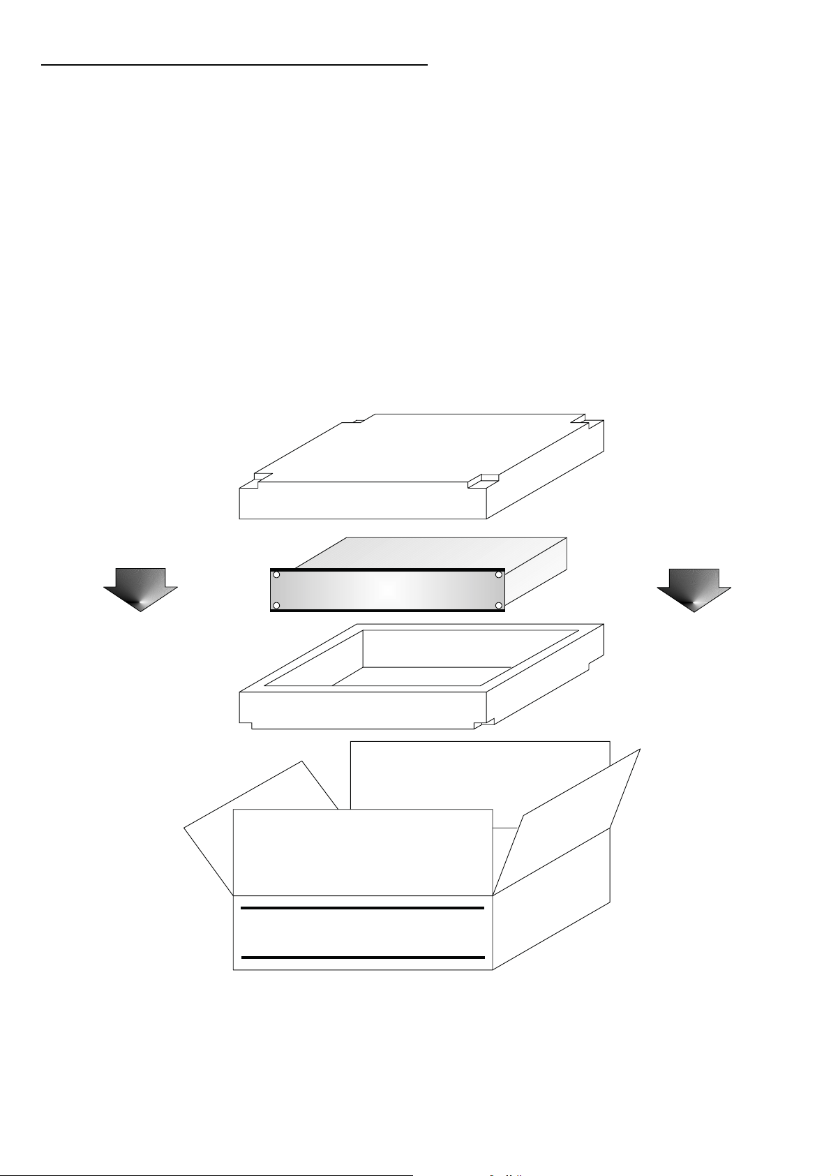
AFTER YOU HAVE UNPACKED THE UNIT
Save all the packing materials - they will prove valuable should it become necessary to transport or ship this
product.
Please inspect this unit carefully for any signs of damage incurred during transportation. It has undergone
stringent quality control inspection and tests prior to packing and left the factory in perfect condition.
If, however, the unit shows any signs of damage, notify the transportation company without delay. Only you,
the consignee, may institute a claim against the carrier for damage during transportation.
If necessary, contact your supplier or as a last resort, your Klark Teknik importing agent, who will fully
co-operate under such circumstances.
This
L
abc
Side Up
Page 5

Introduction
The graphic equaliser is a vital component in any audio system. The entire signal passes through it and so any
limitations imposed by the equaliser will compromise the performance of the whole system. For example, an
indifferently designed equaliser may introduce severe phase distortion, noise and other anomalies related to
centre frequency accuracy, filter shape and attenuation accuracy which may manifest themselves as an overall
deterioration in the perceived sound quality of the system. Clearly, this is an unacceptable state of affairs, but
fortunately your choice to utilise a Klark Teknik graphic equaliser will eliminate these problems, offering you
unprecedented product performance coupled with the highest filter calibration and reliability standards in
the industry.
For many years Klark Teknik has been at the forefront of equaliser design, and have carried our detailed research
into optimum filter response characteristics, including their sonic performance.
The Series 300 range of equalisers is a direct result of this research. It should be noted that graphic equalisation
cannot always overcome all frequency response related problems. There are applications where the ability to cut
and boost the response at a particular frequency, or over a certain bandwidth other than the equaliser specified
one, is required to overcome exceptionally difficult response anomalies or narrow band feedback problems.
When such an instance is encountered, it may be more appropriate to use the greater range of control provided
by a parametic type equaliser, where the centre frequency, bandwidth and amplitude are all controllable.
Reliability is also of paramount importance which is why our filters are designed around a technique commonly
used in computer manufacturing - thick film engineering. This technique has enabled Klark Teknik to build these
new filter circuits into self-contained packages which are referred to as . These micro-electronic
circuits are so consistent and reliable that we are able to warrant those solid state devices for 5 years. This
type of "fit and forget" technology, already proven all over the world, provides users with products that perform
brilliantly year after year.
"MELT"
When using an equaliser remember that the need to use large amounts of booth or that within the equalisation
curve indicates that there may be something fundamentally wrong with the sound system or room acoustics,
which should be further investigated and corrected before final equalisation is applied.
1
Page 6
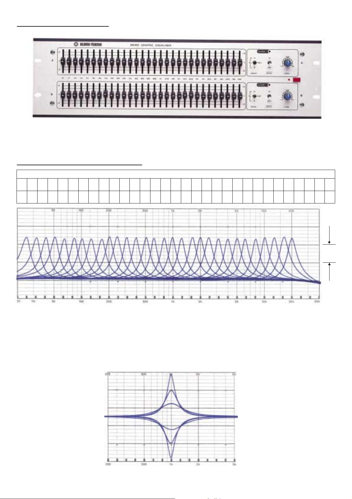
DN360 Graphic Equaliser
The Klark Teknik DN360 is a dual channel, 30 band equaliser offering 12dB of cut or boost in 1/3 octave steps
between the frequencies of 25Hz and 20 kHz.
Filter Shape and Combining Action
ISO CENTRE FREQUENCIES (in Hz)
20 31 50 80 125 200 315 500 800 2K 5K 8K 20K
25 40 63 100 160 250 400 630 1K 4K 10K 16K
1/3 Octave Band Equaliser Filter Curves
1.25K 3.15K 12.5K
1.6K 2.5K 6.3K
5dB
At the heart of any graphic equaliser is the bank of filters used to shape the signal response, and Klark Teknik
utilise a proprietary filter circuit which replaces the conventional inductor based circuit, at the same time,
offering several performance advantages. Inductor based circuits are heavy, expensive to produce and suffer
from low frequency distortion and induced hum. Klark Teknik's proprietary filters on the contrary suffer none
of these problems, yet offer unequaled phase response and control accuracy with the additional benefits of low
noise and minimal ripple.
Single Filter Response Curves (1/3 Octave)
2
Page 7
The nature, shape and way in which individual equaliser filters combine, has a profound effect on the control
provided by the equaliser and on the resulting quality of sound. The majority of applications within the sound
reinforcement, broadcast and recording fields, require a smooth and continuous equalisation response curve in
order to correctly contour the overall response characteristics of a sound system, loudspeaker, recording effect
or audio channel. To achieve this, the individual filters must be capable of combining smoothly together to
result in a continuous response curve, free from shape discontinuities in orders to avoid unwanted audible peaks
or anomalies in the final sound.
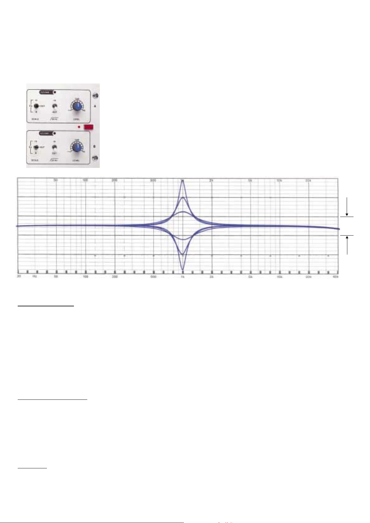
In order to offer operational flexibility a variable fader resolution has been
incorporated i.e. 6 or 12 dB cut or boost. This function ("scale") is combined
with the bypass switch, which silently removes the graphic equaliser section from
the signal path. A subsonic 18dB/octave roll off filter (-3dB @ 3Hz) can be
switched in or out from each of the channels.
5dB
Set of Response Curves for 1/3 Octave Equaliser Filter
Other Features
Other features include an overload LED per channel, which warns of impending overload at any point in the
equaliser. A signal-ground lift switch and an optional security cover to prevent unauthorised personnel from
tampering with the control settings.
This product is built to the same high electrical and mechanical standards as all Klark Teknik equipment and is
both robust and stylish. It occupies a standard three units of rack space and has transformer balanced inputs
and outputs.
Reliability Control
Even the advanced technology incorporated in this product, each instrument is given the full backing of
Klark Teknik's " " which proves each product against a specification consistent with the
highest professional standards. Only top quality components are used, and every unit is bench tested and aligned
before a burn-in period and final performance test.
reliability control
Options
Aluminium security cover Part number: SCA360
Perspex security cover Part number: SCP360
3
Page 8
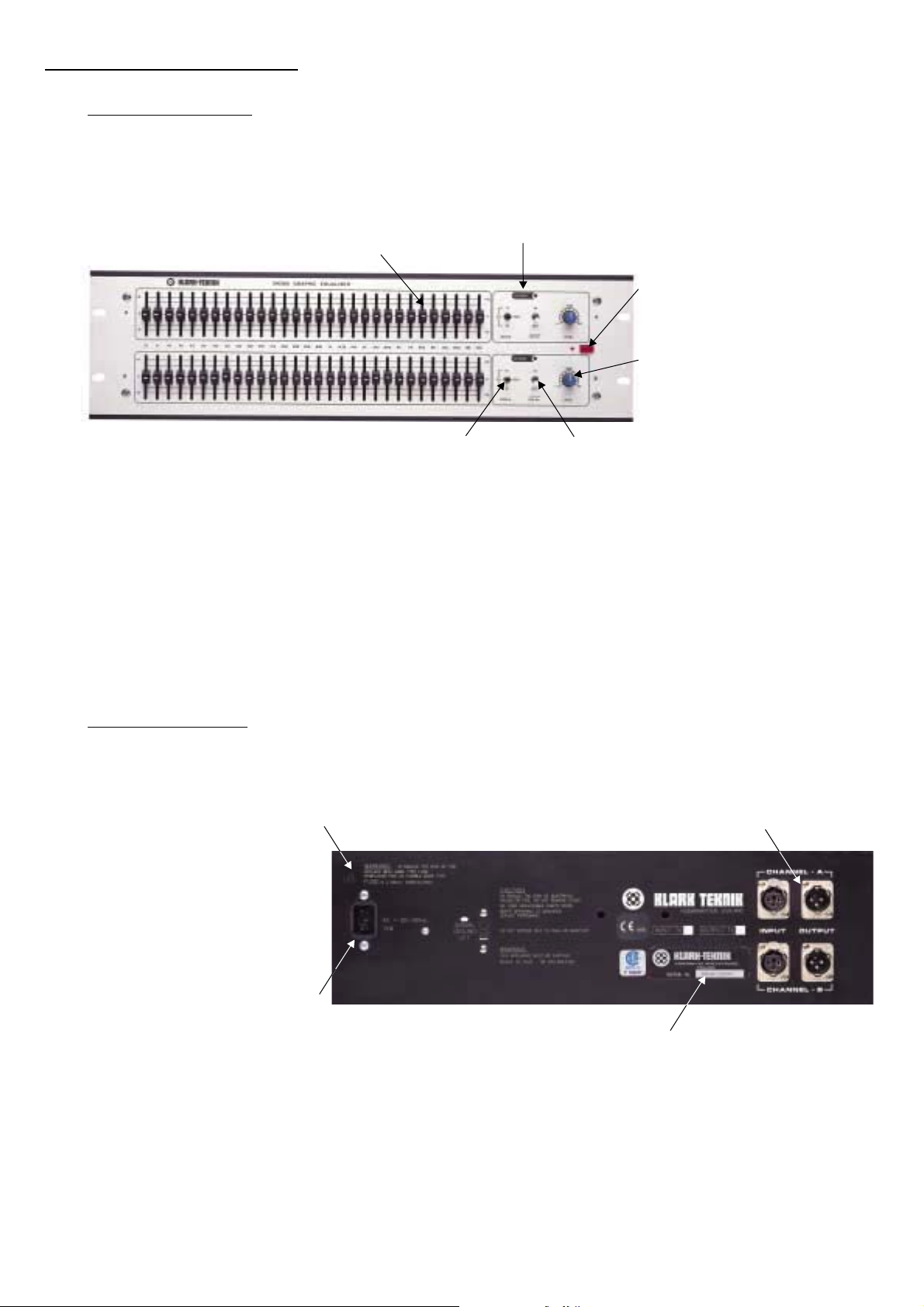
Instrument Familiarisation
Front Panel Functions
The scale switch
for the equaliser of either 6dB or12dB. The centre
position of this switch performs the function,
The high quality faders used in this equaliser have an
oil-damped action for smooth operation and feature a
centre detent following accurate "flat" setting.
The Overload LED The signal level is monitored at several
separate points within the circuitry of the unit, and any one of these
signals exceeding a threshold, set 3dB below clipping, will cause the
LED to light. This threshold is set at +19dB, but it must be remembered
that excessive boost of some frequencies combined with a high average
input signal, can occasionally cause this level to be exceeded. In this
event, the input level control should be turned down to correct the problems.
However, if the input signal itself exceeds +19dBu the input stage will be
overloaded. If this problem arises, the signal level from the output of the
preceding piece of equipment must be turned down.
which silently removes the graphic equaliser section
from the signal path.
selects maximum boost and cut
bypass
The power switch is a two pole type,
isolating both the live and neutral
conductors. When the power is on,
a red status LED lights.
The input level control allows
the system gain to be up to+6dB
when in its fully clockwise position,
and offers full attenuation in
its anti-clockwise position.
Low cut filter switch enables a 30Hz subsonic
filter to be connected in or out of circuit.
Rear Panel Functions
The mains fuse is located in a fuse holder, fitted to the rear panel.
Always replace with the correct type and rating of fuse, as
indicated adjacent to the fuse holder.
Main is supplied via an IEC
standard 3 pin connector. A
compatible power cable
is supplied with the unit.
Input and output connections are made
via complementary XLR style sockets.
The serial number of this unit should be
quoted in any correspondence concerning
the unit.
4
Page 9

Page 10

Specifications
Input
Type
Impedance (
Unbalanced
Output
Type
Min. Load impedence
Source impedance
Max. Level
Performance
Frequency response
Distortion (@ +4dBm)
Equivalent input noise
Channel separation
Overload indicator
Level Control
alanced
Transformer balanced
20k
10k
Transformer balanced
600
dBu
±0.5dB(20Hz-20kHz)
<0.01% @ 1kHz
<-90dBu (20Hz-20kHz unweighted)
>75dB @ 1kHz
+19dBu
+6dB to -
Filters
Type
Centre frequencies
ISO
Tolerance
Maximum boost/cut
Subsonic filter
*MELT - Proprietory Microcircuit
Power Requirements
Voltage
Consumption
Weight
Nett
Shipping
Dimensions
Width
Depth
Height
*MELT
2x30
25Hz - 20kHz 1/3 octave
±5%
±6/12dB
18dB/octave - 3dB @ 30Hz
110/120/220/240V 50/60Hz
<15VA
5Kg
6Kg
482mm (19”)
205mm (8”)
133mm (51/4”)
Terminations
Input
Output
Power
6
3 pin XLR
3 pin XLR
3 pin ICE
Page 11

1999
16:13:29
19
Aug
- Thu
7
B2637-6.sch-1
Page 12

1999
16:13:01
19
Aug
Thu
-
8
B2636-2.sch-1
Page 13

1999
16:12:34
19
Thu Aug
-
9
B2610-4.sch-1
Page 14

10
1999
16:11:23
Aug 19
Thu
-
B2609-2.sch-1
Page 15

1999
16:11:24
19
Aug
Thu
-
11
B2609-2.sch-2
Page 16

12
1999
16:11:25
19
Aug
Thu
-
B2609-2.sch-3
Page 17

The Use of Graphic Equalisers
Equalisers may be used for corrective or creative purposes and the Klark Teknik DN360 is applicable in both
live sound and studio applications.
For studio use, a pair of 1/3 octave equalisers might typically be used to compensate for deficiencies in the
control room acoustics and in this instance, the precision allowed by 30 bands is a great advantage. Because
it is almost impossible to set up an equaliser accurately without first analysing the room response, the centre
frequencies of the filters have been chosen to correspond with those of the Klark Teknik spectrum analyser,
the DN6000. In this way the readings can be transferred directly from the analyser to the equaliser.
It must be stressed however that even a good equaliser doesn't offer a complete solution where the room has
severe, inherent acoustic problems. For example, standing waves and resonances cannot be made to disappear
simply by using equalisation. True their effects can be reduced, but in a critical listening environment such as a
studio control room or concert hall, efforts must be made to minimise these problems at source before
equalisation is employed. Also, equalisation cannot overcome the lack of sound clarity caused by rooms with
unduly long reverberation times though they may be able to effect some improvement in the intelligibility.
On the other hand, the sound company who may well have to set up in different venues night after night have
little or no control over the acoustics of the buildings and so have to use equalisers to arrive at a compromise
solution. Depending on the room, some compromises will be more successful than others. Again, effective use
of the equaliser means employing the services of a spectrum analyser. It is however not always desirable to
achieve a dead flat room response. For example, applying substantial amounts of bass boost to try and restore
a weak bottom end is going to use up large amounts of amplifier power and the extra loudspeaker cone
excursions so caused will rob the system of headroom and may cause distortion. The harmonics produced by
an amplifier driven into clipping may also damage the high frequency drivers and will at any rate sound
unpleasant
Therefore, reducing the low frequency output may produce real advantages by way of improved intelligibility
and subjective naturalness and this is particularly true of buildings made from concrete or stone where much
of the bass is reflected rather than absorbed. Equally, rolling off the high frequency end above 5kHz may also
contribute to a more natural sound. The resulting house curve then is far from flat but may will be the ideal
compromise. Depending on the individual sound system and the environment, the shape of the optimum
house curve will vary and a degree of experience is needed in order to achieve the best results. It should also
be borne in mind that the ideal house curves for pure speech and music will not be the same.
+10
0
dB
-10
-20
100 1k 10k
Frequency Hz
Typical House Curve
13
Page 18

In live sound applications, graphic equalisation is almost always applied separately to the stage monitor of
foldback system to reduce the level of those frequencies that would otherwise cause feedback problems. These
problems came about due to peaks in the frequency response curves of the monitor speaker systems, monitor
positioning, and sound reflected from the stage walls. An analyser is probably best employed to do this
effectively but many experienced engineers rely on their ears.
In addition to compensating for room acoustics, equalisation can also be used to counteract some of the
problems caused by microphone characteristics and positioning or to tailor the response to improve speech
intelligibility. Also, many speaker systems have a far from flat response, particularly mobile systems that
have to be positioned in physically convenient places rather than the acoustically ideal ones. When equalising
the room, these deficiencies are also catered for to a large extent.
Whatever the application, it is generally better to try to attenuate peaks rather than to attempt to boost the
surrounding frequencies to the same level, Furthermore, all peaks can be reduced be attenuating their respective
band but some response dips simply cannot be corrected. An example is crossover cancellation where very
deep notches may appear covering two or three bands. Attempting to level the response by excessive boosting
will simply eat up system power and achieve no useful result. Ultimately a dip in the response is not so audibly
objectionable as a peak and so it may be as well to leave these dips alone or to try and solve the problem at
source by checking your crossover systems and horn alignment.
In broadcast studios, graphic equalisers are often used during phone-in shows to help compensate for the
restricted bandwidth of telephone lines. No equaliser can completely correct the signal in this way as it is
impossible to boost frequencies that don't exist and telephone lines have a very restricted bandwidth.
Nevertheless, the improvement in subjective terms can be dramatic.
Creative uses may include studio work, live or recorded drama and film soundtrack recordings. Voices may
be harshly filtered to simulate telephone conversation or the tonal characteristics of an instrument may be
modified to fit in with a particular mix.
Though other types of equaliser can often to this job, the graphic equaliser is still the easiest to set up and the
controls give an instant visual presentation of the response curve. In the commercial studio where time is often
of the essence, this attribute should not be overlooked.
14
Page 19

Table 1: Effects of Equalisation on Voice Reproduction
1/3 Octave centre frequency (Hz)
40, 50, 63, 80,100,125,
160, 200, 250,
315, 400, 500
630, 800, 1k
1.25 to 4k
5, 6.3, 8k
10,12.5, 16k
Effect on voice
Sense of power in some outstanding
bass singers.
Voice fundamentals.
Important for voice quality.
Important for voice naturalness. Too
much boost in the 315 to 1k range
produces a telephone like quality.
Vocal fricatives - accentuation of vocals.
Important to speech intelligibility. Too
much boost between 2 and 4kHz can
mask certain speech sounds e.g “m”, “b”
and “v” can become indistinguishable.
Too much boost anywhere between 1 and
4kHz can produce “listening fatigue”.
Vocals can be highlighted by slightly
boosting the vocal at 3kHz and at the
same time slightly dipping the instruments
at the same frequency.
Accentuation of voice.
The range from 1.25 to 8k governs the
clarity of voice.
Too much boost causes sibilance.
Table 2: Effects of Equalisation on Music Reproduction
1/3 Octave centre frequency (Hz)
31,40, 50, 63
80, 100, 125
160, 200, 250
315, 400, 500
630, 800, 1k
1.25 to 4k
Effect on music
Fundamentals of bass drum, tuba, double
bass and organ. These frequencies give
music a sense of power. If overemphasised they make the music “muddy”.
50 or 60Hz band also used to reject ac.
Mains hum.
Fundamentals of lower tympani. Too much
boost produces excessive “boom”. 100 or
125Hz also used for hum rejection.
Drum and lower bass. Too much boost
produces excessive “boom”. Also useful
for 3rd harmonic mains hum rejection.
Fundamentals of string and percussion.
Fundamentals and harmonics of strings,
keyboards and percussion.
Boosting the 600 - 1kHz range can make
instruments sound horn like.
Drums, guitar accentuation of vocals,
strings and brass.
Too much bass in the 1 to 2kHz range can
make instruments sound tinny. Too much
boost anywhere between 1 to 4kHz can
produce “listening fatigue”.
5,6.3, 8k
10, 12.5, 16k
Accentuation of percussion, cymbals and
snare drum.
Reduction at 5kHz makes overall sound
more distant and transparent.
Reduction of tape hiss and system noise.
The 1,25 to 8k governs clarity and
definition.
Cymbals and overall brightness. Too much
boost causes sibilance.
Reduction of tape hiss and system noise.
15
Page 20

Equalising a Sound System
When equalising a sound system you should always remember just what it is you are trying to achieve. Two
fundamental reasons for equalization are:-
1. To increase the potential gain or power output of the system before feedback.
2. To improve the naturalness or intelligibility of the sound system.
In a space with poor acoustics or high levels of background noise, the most natural sound may well not be the
most intelligible - a compromise must therefore by reached between these two qualities depending on the
particular application in question - but at the end of the day it doesn’t matter how natural the system sounds if
no one can understand the sound it puts out!
Sound System Equalisation
EQ
Pink
Test Microphone
Noise
general.
Spectrum
Analyzer
Sound System Equalisation
Before beginning to equalise a system, it is a good practice to listen to the “raw” system with speech or music
programme. If such signals are distorted then stop and rectify them before attempting to equalise. Another good
pre-equalisation test is to use a slow sine-sweep. This can expose a number of problems such as rattles or
distortion or poorly controlled room modes and resonances - which pink noise RTA cannot discover. Finally,
before equalisation, check the coverage of the system over the 2 to 4kHz bank. (If necessary, use the equaliser
as a band pass filter to produce the desire range). If coverage is poor to begin with then no amount of
equalisation will overcome this. Again adjustments to the system itself are required. Equalisation is the final
tuning stage. Generally, a gradual transition between adjacent bands should be aimed for, particularly in studio
monitoring situations where the maximum difference between bands should only be 3dB or so. A warning bell
should be ringing if you are using much more than this! This does not mean however that more drastic
adjustments should not be used - this is very often necessary with sound systems operating in poor or severe
acoustic environments, but the reason why such a particularly large fader excursion is being used at a given
frequency should always be carefully considered.
Once satisfied with the basic system, performance equalisation can begin. If using a real time analyser ensure
that the microphone is in a sensible position i.e within the coverage area of the system and not in an area where
strong local acoustics effects might be expected such as within 1 metre of a rear or side wall or in a balcony
opening.
16
Page 21

A good idea is to rotate the measuring microphone in a wide arc or circle round the measuring position and to
see if any strong interactions occur causing large deviations in response. If necessary, move to another position.
Also ensure that the ambient noise level is at least 6dB (preferably 10dB) below the signal level you are using.
Having set up the desired house curve as smoothly as possible, move round and check the response throughout
the listening area. Good equalisation requires time and patience. Do not forget that some interaction will occur
between a particular filter and its adjacent bands. A better sound may be produced by adjusting several bands
rather than by strong cutting just the centre one. Do not forget to pause to talk or play music through the system
as you go, so that you keep in touch with what the resultant sound quality is like.
If the Real Time Analyser you are using is the Klark Teknik DN6000 you have a powerful averaging capability
which means that averaging the response throughout the coverage area becomes very much easier. The
response displayed by the analyser should also become smoother as local fluctuations are averaged out whilst
persistent peaks and dips clearly stand out and show where adjustment is truly required.
DN6000
Connecting a stage or house microphone into the analyser can be a most instructive exercise - showing up
any local reflection or acoustic resonance or loudspeaker sidelobes. Generally repositioning the microphone
or adjusting individual microphone channel equalisation will be needed, rather than adjustment to the overall
house curve. This technique is particularly useful when investigating acoustic feedback after the initial house
curve has been set.
17
Page 22

Inserting the Equaliser in the Signal Chain
The exact point of insertion of an equaliser into the signal chain will very much depend on the task in hand e.g.
mixer channel / line input, group insert point, group output, auxiliary send or between another signal processing
device and the mixer or power amplifier, etc. when using delayed out signals for example, i.e. where a digital
delay line is being used to synchronise sound arrivals in order to maintain intelligibility or source directionality,
the option may exist to insert the equaliser either before or after the delay line e.g. In a conference venue
employing similar loudspeaker types throughout the system, but connected to different delay outputs, the
equaliser can be inserted before the delay line. In a more complex system where several loudspeaker types are
employed, or where the local acoustic environment differs within the same system e.g. theatre system with a
central loudspeaker cluster and delayed side fills or underbalcony speakers, each delay channel will need its
own separate equaliser in order to satisfactorily equalise out either the different loudspeaker responses or the
effects of the different local acoustic environment.
Digital Delay
Line
Mixer
Recording / Broadcast Monitor Outputs
Equaliser
Equaliser
Equaliser
Typical Sound Theatre System
X-Over
Central Cluster
Power Ampifiers
Side Fills
Under Balcony
or
Balcony Loudspeakers
Equaliser Limitations
The equaliser is not the answer to poor sound system design - but instead it should be considered as a final
tuning measure - such final tuning can often bring about quite remarkable improvements to the overall
intelligibility and perceived sound quality of a system.
After an equaliser, a security cover is probably the most useful accessory a sound system could have.
Equalisers, when used competently, can do wonders for your system - but when used badly.........
18
Page 23

Important Note:
It is often useful to call your dealer or the factory explaining the nature of the problem with the unit. In many
instances the problem can be solved without returning the unit to the factory. If the unit has to be returned to the
factory, use original packing only. If you do not have one, we will provide replacement.
Factory authorised service facilities are located throughout the world. Call your dealer or the factory for the
location of the service facility nearest you.
Klark Teknik Group.
Klark Teknik Building,
Walter Nash Road,
Kidderminster.
Worcs.
DY11 7HJ.
England.
Tel: +44 (0) 1562 741515
Fax: +44 (0) 1562 745371
19
Page 24

O
Notes
O
C’’’’’’8372.0
O
B’’’’’ 7902.2
O
A’’’’’ 7040.0
O
G’’’’’ 6271.9
O
F’’’’’ 5567.6
O
E’’’’’ 5274.0
O
D’’’’’ 4498.6
O
FREQUENCY RANGE CHART
O
O
O
D’’’ 1174.7
O
C’’1046.5
O
B’’987.8
O
A’’880.0
O
G’’783.0
O
F’’698.4
O
E’’659.2
O
D’’587.3
O
C’ 523.2
O
B’ 493.9
O
A’ 440.0
O
&
?
O
O
D’’’ 18.4
C’’’’ 16.4
O
O
E’’’ 20.5
O
O
G’’’ 24.5
F’’’ 21.9
O
O
B’’’30.9
A’’’ 27.5
O
O
D’’36.7
C’’’ 32.7
O
F’’43.7
E’’41.2
O
O
G’’49.0
O
B’’61.7
A’’55.0
O
O
C’’65.0
O
E’ 82.4
D’ 73.4
O
F’ 87.3
O
G’ 98.0
O
O
A’ 110.0
O
O
C’ 130.8
B’ 123.5
O
O
E 164.8
D 146.6
O
O
G 196.0
F 174.6
O
B 246.9
A 220.0
G’392.0
O
F’ 349.2
O
E’ 329.6
O
D’ 293.7
C 261.6
NOTES RELATED TO FREQUENCIES
This chart shows (above) the musical notes and octaves related to their
Mid C
actual frequencies. The details are cross references (below) to the
O
O
O
G’’’ 1568.0
F’’’ 1396.9
E’’’ 1318.5
O
O
O
C’’’ 2093.0
B’’’’ 1975.6
A’’’ 1760.0
O
E’’’’2637.0
D’’’’2249.3
O
O
O
G’’’’ 3135.9
F’’’’ 2793.8
B’’’’ 3951.1
A’’’’
3520.0
C’’’’ 4186.0
frequency range of our Graphic Equalisers and the range capabilities of
common musical instruments
’’’
G
A
F
E
D
C
25 31 40 50 63 80 100 125 160 200 250 315 400 500 630 800 1 1 25 1 6 2K 2K5 3 15 4 5 6 3 8 10 12 5 16 20KK K K KKK K KK KK
’’
G
C
A
E
B
D
F
’
G
C
B
A
E
D
B
F
G
C
A
E
D
F
’
G
C
E
B
D
A
F
’’
G
C
E
B
A
D
F
’’’
G
C
B
A
E
D
F
’’’’
G
C
B
A
E
D
F
’’’’’
C
A
B
G
C
E
B
D
F
Octaves
Hz
OCTAVES
NOTES
FREQUENCY
DN360
Human Hearing Range
VOCAL
Soprano
Contralto
Baritone
Bass
WOODWIND
Piccolo
Flute
Oboe
Clarinet in B flat or A
Clarinet in E flat
Bass Clarinet
Basset Horn
Cor Anglais
Bassoon
Double Bassoon
BRASS
Soprano Saxaphone
Alto Saxaphone
Tenor Saxaphone
Baritone Saxaphone
Bass Saxaphone
Trumpet in C
Trumpet in F
Alto Trombone
Tenor Trombone
Bass Trombone
Tuba
Valve Horn
STRINGS
Violin
Viola
Cello
Double Bass
Guitar
KEYBOARDS
Pianoforte
Organ
PERCUSSION
Celeste
Timpani
Glockenspiel
25 31 40 50 63 80 100 125 160 200 250 315 400 500 630 800 1 1 25 1 6 2 2 5 3 15 4 5 6 3 8 10 12 5 16 20KKKKKKKKKKKKKK
Xylophone
20
Page 25

A
B
A
B
O/LOAD
+12
+6
0dB
IN
12
LEVEL
88
-
OUT
30 Hz
OUT
6
SCALE
Eq
0
-12
20k
16k
12k5
10k
8k
6k3
5k
4k
3k15
2k5
2k
O/LOAD
+12
0dB
+6
LEVEL
-
IN
OUT
30 Hz
OUT
6
12
SCALE
Eq
0
-12
Date:
O/LOAD
+12
Location:
+6
0dB
IN
12
LEVEL
88
-
OUT
30 Hz
OUT
6
SCALE
Eq
0
-12
O/LOAD
+12
20k
16k
12k5
10k
8k
6k3
5k
4k
3k15
2k 2k5
0dB
+6
LEVEL
-
IN
OUT
30 Hz
OUT
6
12
SCALE
Eq
0
-12
Date:
Location:
Please photocopy when required
Copymaster Do Not Remove
DN 360 GRAPHIC EQUALISER
1k6
1k25 1k6
1k
800
630
500
Serial No:
DN 360 GRAPHIC EQUALISER
315 400
250
200
160
100 125
80
63
50
40
31
0
+6
25
-6
A
0
+6
-6
B
0
+6
A
1k25
1k
630 800
500
400
315
250
160 200
125
100
80
50 63
40
31
25
-6
0
+6
-6
Serial No:
B
Fader Setting Record Chart: Equaliser No:
21
Fader Setting Record Chart: Equaliser No:
 Loading...