

KitchenAid Undercounter Dishwasher 8564554 Installation Instructions Manual
Installation Instructions
Undercounter Dishwasher
8564554
8564554
8564554
Instrucciones de Instalación
Lavavajillas empotrado
Instructions d'installation
Lave-vaisselle encastré
®
HOME APPLIANCES
You need to:
• Slowly open dishwasher door while someone grasps the
rear of the dishwasher. Remove shipping materials, drain
hose and lower rack. Close dishwasher door until latched.
• Observe all governing codes and ordinances.
• Install this dishwasher as specified in these instructions.
• Installation should be performed by a qualified service
technician. The dishwasher must be installed to meet all
electrical and plumbing national and local codes and
ordinances.
2
Table of Contents
Dishwasher Safety . . . . . . . . . . . . . . . . . . . . . . . . . . . . . . . . . 2
Installation Requirements . . . . . . . . . . . . . . . . . . . . . . . . . . . 3
Tools and parts . . . . . . . . . . . . . . . . . . . . . . . . . . . . . . . . . 3
Location Requirements . . . . . . . . . . . . . . . . . . . . . . . . . . 3
Drain Requirements . . . . . . . . . . . . . . . . . . . . . . . . . . . . . 5
Water Supply Requirements . . . . . . . . . . . . . . . . . . . . . . 5
Electrical Requirements . . . . . . . . . . . . . . . . . . . . . . . . . . 5
Dishwasher Safety
Installation Instructions. . . . . . . . . . . . . . . . . . . . . . . . . . . . . 6
Prepare cabinet opening
using existing utility hookups . . . . . . . . . . . . . . . . . . . . . 6
Prepare cabinet opening
where there are no existing utility hookups. . . . . . . . . . 7
Prepare dishwasher . . . . . . . . . . . . . . . . . . . . . . . . . . . . . 9
Make electrical connection . . . . . . . . . . . . . . . . . . . . . . 12
Connect to water supply . . . . . . . . . . . . . . . . . . . . . . . . 13
Connect to drain . . . . . . . . . . . . . . . . . . . . . . . . . . . . . . . 14
Secure dishwasher in cabinet opening . . . . . . . . . . . . . 14
Your safety and the safety of others are very important.
We have provided many important safety messages in this manual and on your appliance. Always read and obey all safety
messages.
This is the safety alert symbol.
This symbol alerts you to potential hazards that can kill or hurt you and others.
All safety messages will follow the safety alert symbol and either the word “DANGER” or “WARNING.”
These words mean:
You can be killed or seriously injured if you don't immediately
DANGER
WARNING
All safety messages will tell you what the potential hazard is, tell you how to reduce the chance of injury, and tell you what can
happen if the instructions are not followed.
follow instructions.
can be killed or seriously injured if you don't
You
instructions.
follow
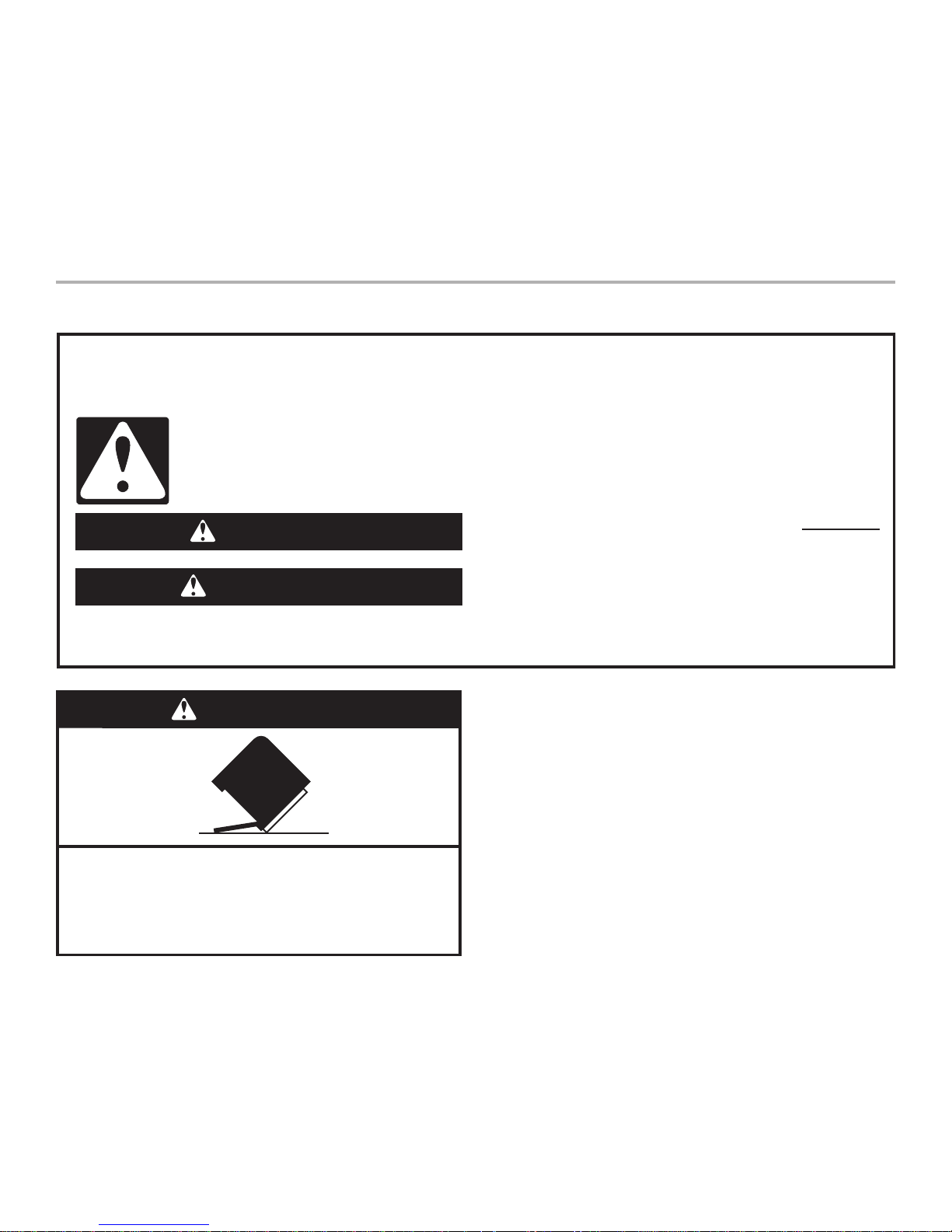
WARNING
Tip Over Hazard
Do not use dishwasher until completely installed.
Do not push down on open door.
Doing so can result in serious injury or cuts.
3
® Teflon is a registered trademark of E.I. Du Pont de Nemours and
Company.
® Registered trademark of TEXTRON.
Tools needed:
• electric drill with 1/2", 3/4"
and 1-1/2" hole saw bits
• small tubing cutter
• wire stripper
• 1-1/2"-2" screw-type clamp
if connecting to waste-tee
Parts needed:
• copper tubing (3/8"
recommended) or flexible
stainless steel braided fill
line
• clamp connector or
conduit connector to fit a
7/8" (2.2 cm) diameter hole
Tools needed:
• pliers
• Phillips screwdriver
• 5/16" and 1/4" nut drivers
or hex sockets
• measuring tape or ruler
• 10" adjustable wrench that
opens to 1-1/8" (2.9 cm)
• flat-blade screwdriver
• utility knife
• 2 twist-on wire connectors
which are the proper size
to connect your household
wiring to 16-gauge wiring
in dishwasher
• small level
• TORX
®
T15 screwdriver (if
installing custom front
panels)
• flashlight
• shallow pan
• electric drill with 3/32" bit
• 5/8" open-end wrench
• bath towel
• wood block
Parts needed:
• 90° elbow with 3/8" N.P.T.
external threads on one
end. (The other end must
fit your water supply line.)
• Teflon
®
tape or pipe joint
compound
• shims (if installed with
built-up floor)
• 4 #10 x 1/2" wood screws
(if installing custom front
panels)
Tools and Parts
Gather the required tools and parts before starting
installation. Read and follow the instructions provided with
any tools listed here.
All installations
In addition, for new installations
A
B
C
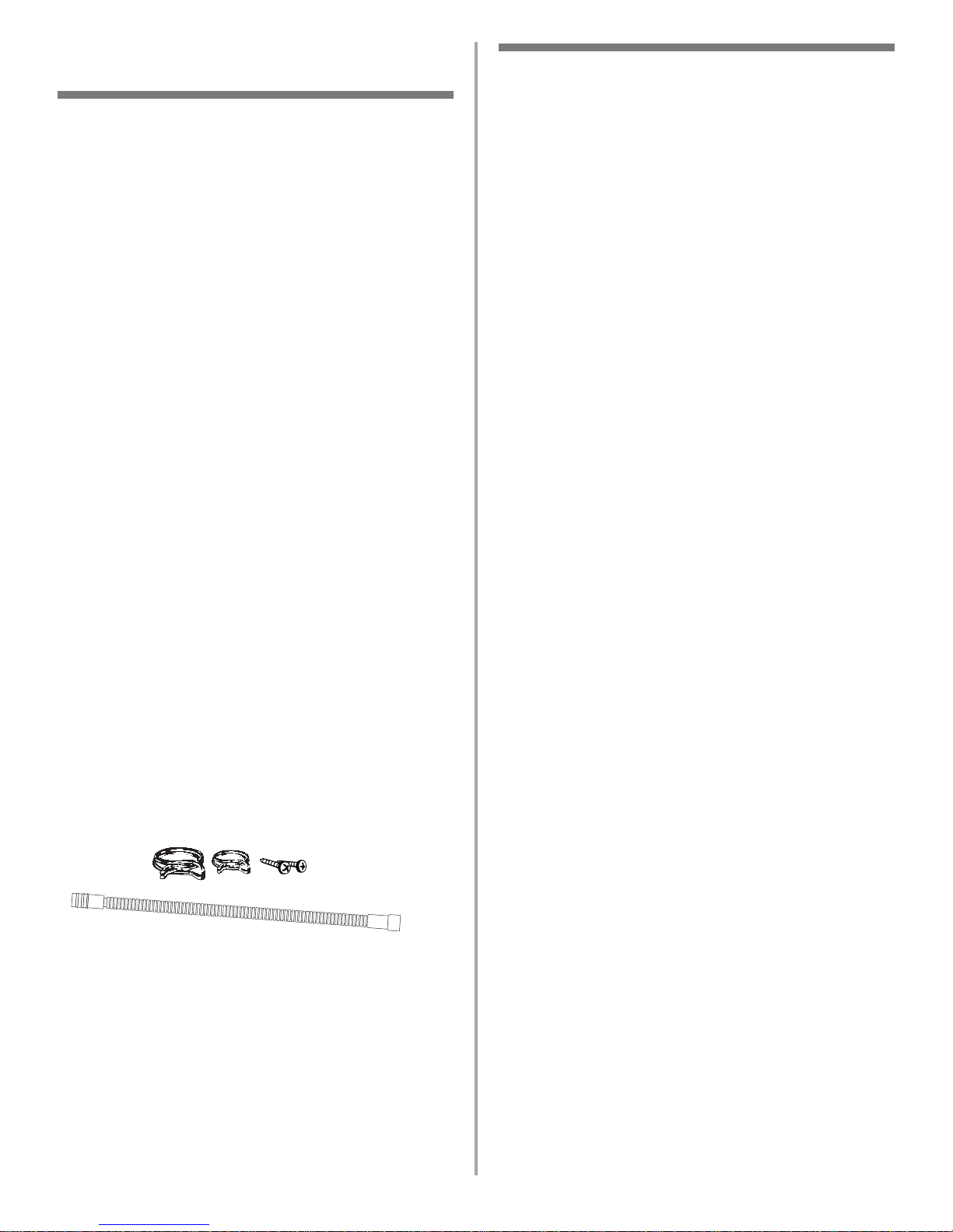
Parts supplied
A. 2 – drain hose clamps, 1 large and 1 small
B. 2 – # 10 x 1/2" Phillips-head screws
C. drain hose
Additional parts supplied with top-venting models only
D. 2 #8 x 1-3/8" TORX
®
T15 screws
E. 4 #10 x 3/8" hex-head screws
Additional part supplied with certain models
F. Bottom sound pad (located in upper rack)
Make sure all these parts are included. If not included, call
1-800-422-1230.
See separate parts list for accessories available for your
dishwasher.
Installation Requirements
Location Requirements
Do not run drain lines, water lines or electrical wiring
where they can interfere with or contact dishwasher motor
or legs.
The location where the dishwasher will be installed must
provide clearance between motor and flooring. Motor
should not touch the floor.
Do not install dishwasher over carpeted flooring.
Protect dishwasher and water lines leading to dishwasher
against freezing. Damage from freezing is not covered by
the warranty.
A side panel kit is available from your dealer for installing
your dishwasher at the end of your cabinetry.
A moisture barrier accessory (Part No. 4396277) is available
from your dealer for installing underneath the countertop,
but is not required. This may also be obtained by calling
1-800-422-1230.
Check location where dishwasher will be installed. The
location must provide:
• easy access to water, electricity and drain.
• convenient access for loading and unloading dishes.
Corner locations require a 2" (5.1 cm) minimum clearance
between the side of the dishwasher door and the wall or
cabinet.
• square opening for proper operation and appearance.
• cabinet front perpendicular to floor.
• level floor. (If floor at front of opening is not level with
floor at rear of opening, shims may be needed to level
dishwasher.)
NOTE:To prevent shifting during dishwasher operation,
shims must be securely attached to the floor.
If dishwasher will be left unused for a period of time or in a
location where it may be subject to freezing, have it
winterized by authorized service personnel.
Make sure pipes, wires and drain hose are within the
shaded area shown in the “Cutout dimensions” section.
Helpful Tip: If the floor in the dishwasher opening is
uneven (example: tile flooring only partway into
opening) you will need to take special care in
measuring dimensions and in leveling dishwasher.
4
9"
(22.9 cm)
10"
(25.4 cm)
6" ***
(15.2 cm)
6" ***
(15.2 cm)
3-1/4"
(8.3 cm)
2-3/4"
(7 cm)
34"
(86.4 cm)
min.*
2"
(5.1 cm)
2"
(5.1 cm)
All surfaces must be free
from intrusions
2"
(5.1 cm)
3-1/4"
(8.3 cm)
3-1/4"
(8.3 cm)
2-3/4"
(7 cm)
3-1/4"
(8.3 cm)
24" (61 cm)
min.
24" (61 cm)
**
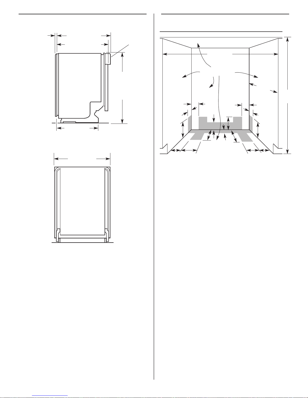
Cut holes in shaded area of cabinet walls or floor as specified below:
water line – 1/2" (1.3 cm)
drain line – 1-1/2" (3.8 cm)
direct wire – 3/4" (1.9 cm)
power supply cord – 1-1/2" (3.8 cm)
* Measured from the lowest point on the underside of countertop. May be
reduced to 33-7/8" (86 cm) by removing wheels from dishwasher.
** Minimum, measured from narrowest point of opening.
*** May be increased to 6-5/8" (16.6 cm) if height of opening is 34-1/2"
(87.6 cm) at its lowest point.
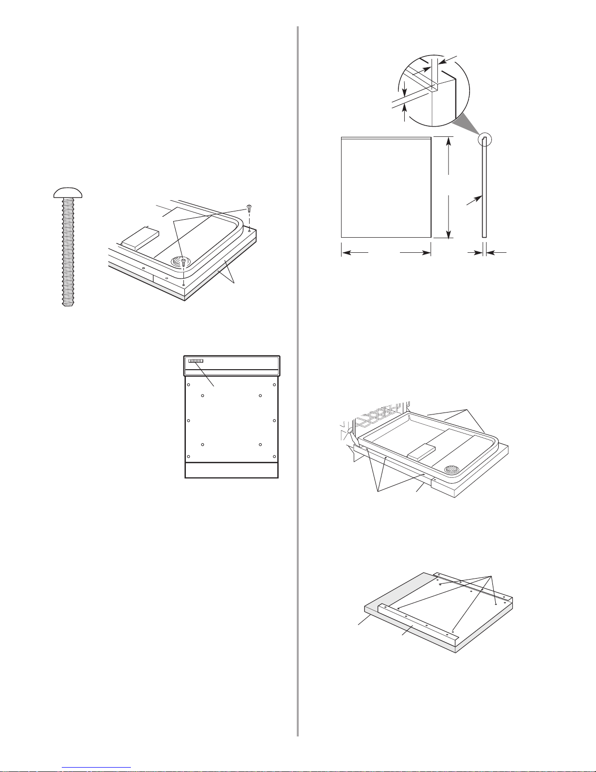
Cutout dimensions
5-1/2"
(14 cm)
3-1/2"
(8.9 cm)
Product dimensions
23-7/8" (60.6 cm)
SIDE VIEW
REAR VIEW
24-7/8" (63.2 cm)
3/4" (1.9 cm)
insulation –
may be
compressed
(not used on
all models)
24-1/2" (62.2 cm)*
front vent
21" (53.3 cm)
33-7/8"
(86 cm) min.
with wheels
removed
5
Drain Requirements
• Use the new drain hose supplied with your dishwasher.
If this is not long enough, use a new drain hose with a
maximum length of 12 feet (3.7 m) that meets all
current AHAM/IAPMO test standards, is resistant to
heat and detergent, and fits the 1" (2.5 cm) drain
connector of the dishwasher.
• Connect drain hose to waste tee or disposer inlet
above drain trap in house plumbing and 20" (50.8 cm)
minimum above the floor. It is recommended that the
drain hose either be looped up and securely fastened
to the underside of the counter, or be connected to an
air gap.
• Use an air gap if the drain hose is connected to house
plumbing lower than 20" (50.8 cm) above subfloor or
floor.
• Use 1/2" minimum I.D. drain line fittings.
Water Supply Requirements
• A hot water line with 20-120 psi (138-862 kPa) water
pressure.
• 120°F (49°C) water at dishwasher.
• 3/8" O.D. copper tubing with compression fitting or
flexible stainless steel braided fill line (1/2" minimum
plastic tubing is not recommended).
• A 90° elbow with 3/8" N.P.T. external pipe threads on
one end.
Do not solder within 6" (15.2 cm) from water inlet valve.
Electrical Requirements
Contact a qualified electrician.
Assure that the electrical installation is adequate and in
conformance with all national and local codes and
ordinances.
You must have:
• 120-volt, 60 Hz, AC-only, 15 or 20 amp., fused electrical
supply.
• Copper wire only.
We recommend:
• A time-delay fuse or circuit breaker.
• A separate circuit.
If direct wiring dishwasher:
• Use flexible, armored or non-metallic sheathed, copper
wire with grounding wire that meets the wiring
requirements for your home and local codes and
ordinances.
• Use strain relief method provided with house wiring
junction box or install a U.L.-listed/CSA-certified clamp
connector to the house wiring junction box. If using
conduit, use a U.L.-listed/CSA-certified conduit connector.
If connecting dishwasher with a power supply cord:
• Use Power Supply Cord Kit (Part No. 4317824) marked for
use with dishwashers. Kit contents include:
– Volex, Inc., UL listed 16 gauge 3 wire power supply
cord with 3 prong grounded plug.
– Neer C-500 7/8 inch strain relief.
– 3 wire connectors.
– Part No. 302797 grommet
Follow the kit instructions for installing the power
supply cord.
• Power supply cord must plug into a mating three prong,
grounded outlet, located in the cabinet next to the
dishwasher opening. Outlet must meet all local codes and
ordinances.
air gap
6
Installation Instructions
1. Disconnect power.
2. Turn off water supply.
Prepare cabinet opening using
existing utility hookups
• Follow the steps in this section if you are installing the
dishwasher in an existing cabinet opening with utility
hookups.
• If you are installing the dishwasher in a cabinet opening
that does not have hookups, follow the steps under
"Prepare cabinet opening where there are no existing
utility hookups" section.
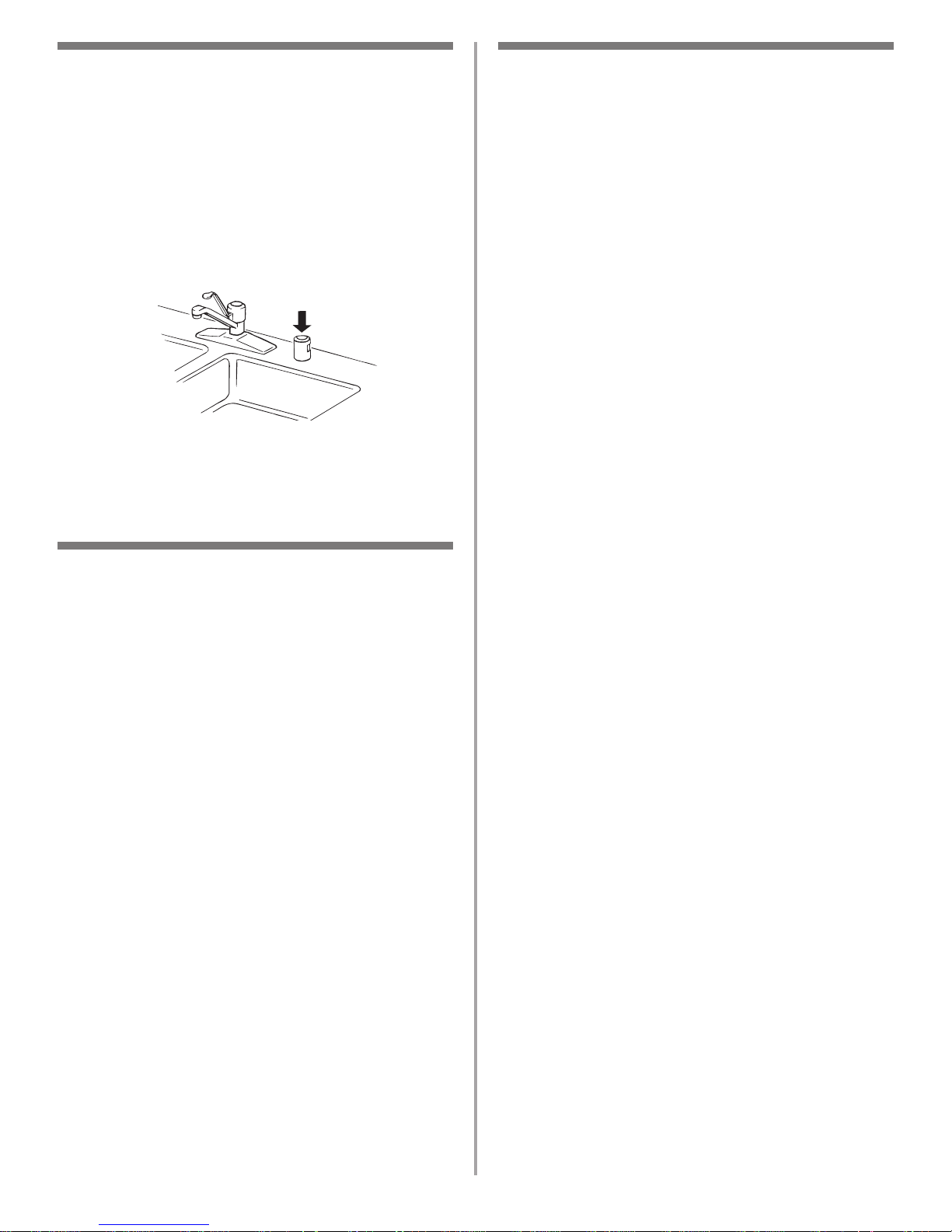
1. Check that the water
line reaches to the
front left of opening
where the water
connection will be
made.
2. Check that the direct
wire reaches to the
front right of opening
where the electrical
connection will be made.
If the water line and the direct wire reach far enough into
the opening, proceed to the next section “Install the drain
hose.“ If they do not reach far enough, follow the steps
under “Prepare cabinet opening where there are no
existing utility hookups.”
6" (15.2 cm)
water
line
direct
wire
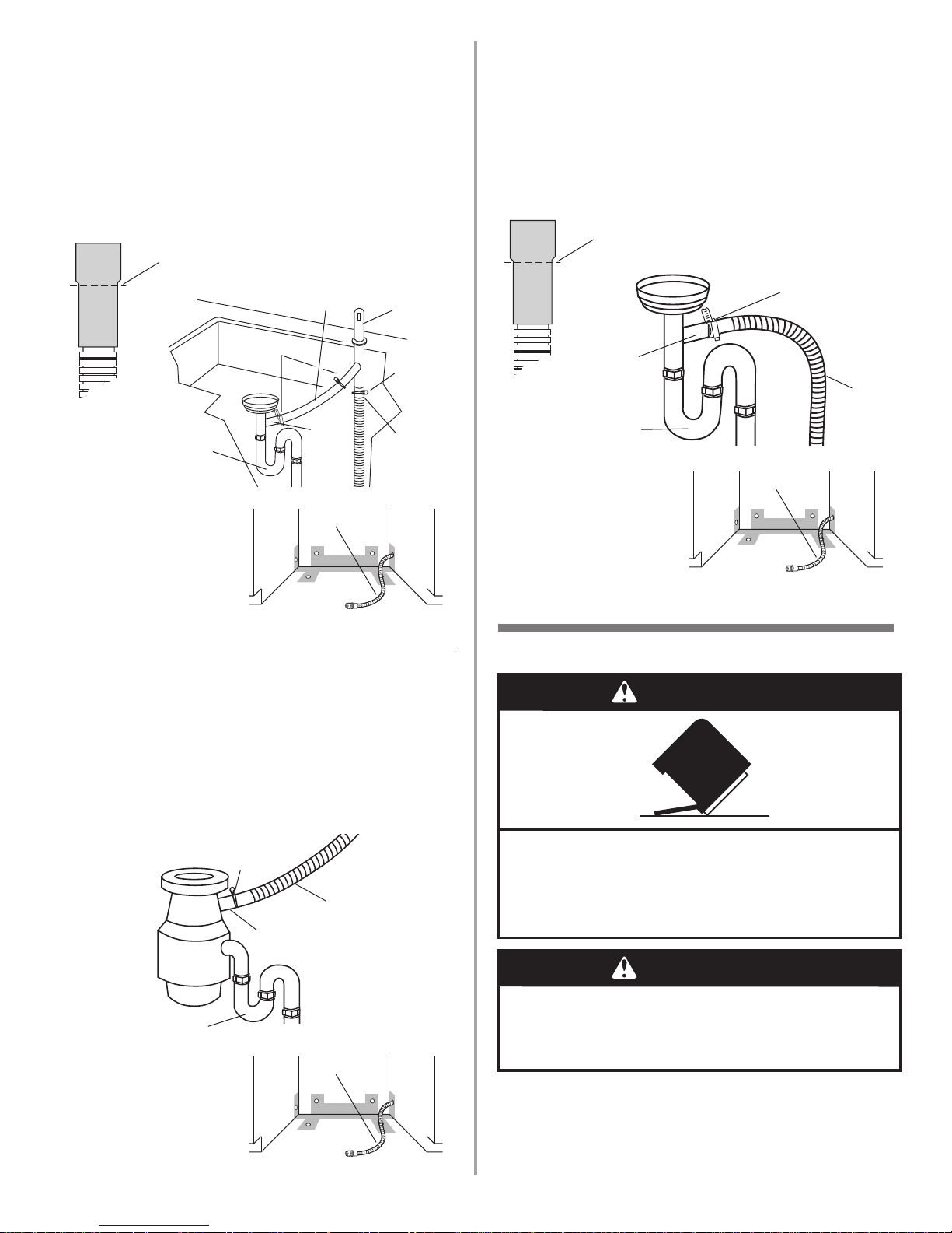
Install the drain hose
IMPORTANT: Always use a new drain hose even when
installing a new replacement dishwasher.
1. Drill a 1-1/2" (3.8 cm) diameter hole in cabinet wall or
floor on the side of the opening closest to the sink.
2. Connect drain hose to waste tee or waste disposer
using one of the following methods:
• Option 1, Waste disposer – with air gap
• Option 2, No waste disposer – with air gap
• Option 3, Waste disposer – no air gap*
• Option 4, No waste disposer – no air gap*
*an air gap is recommended
Helpful Tip: To reduce the vibration of the hose, keep
the hose away from the floor and the edge of the hole
where it passes through the cabinet.
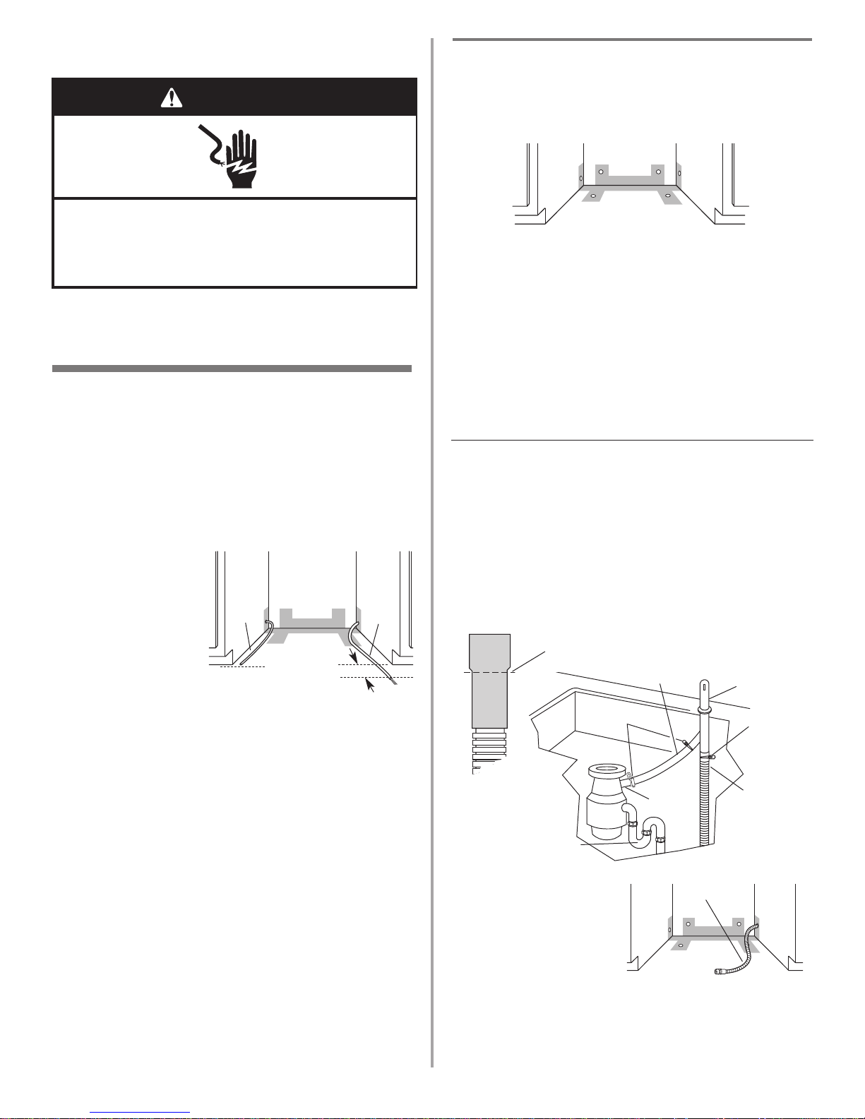
Option 1: Waste disposer – with air gap:
1. Remove the disposer knockout plug. Cut end of drain
hose if needed (do not cut ribbed section).
2. Attach drain hose to air gap with large spring-type
clamp. If the drain hose was cut, use a 1-1/2" to 2"
(3.8 to 5 cm) screw-type clamp*.
3. Use a rubber hose connector* with spring or screwtype clamps* to connect air gap to disposer inlet.
This connection must be before the drain trap and at
least 20" (50.8 cm) above the floor where dishwasher
will be installed.
4. Insert drain hose
through hole cut in
cabinet to the front
center of opening where
drain connection will be
made.
* Parts available from local plumbing supply stores
drain
hose
large
spring-type
clamp
air gap
rubber hose
connector
disposer
inlet
drain trap
drain hose –
cut here if needed
spring or
screw-type
clamps
drain hose
WARNING
Electrical Shock Hazard
Disconnect electrical power at the fuse box or circuit
breaker box before installing dishwasher.
Failure to do so can result in death or electrical shock.
7
Prepare cabinet opening where there
are no existing utility hookups
Electrical connection
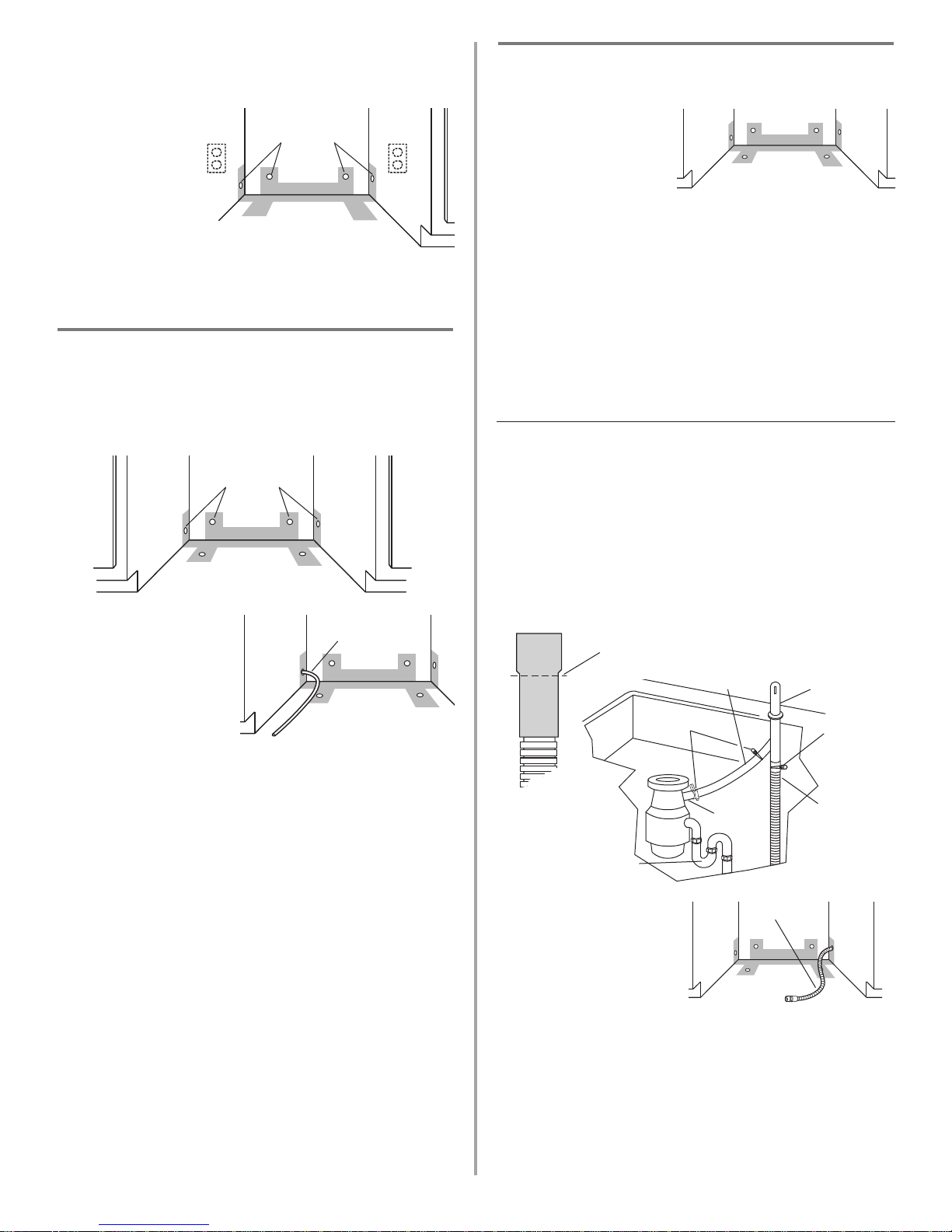
Option1: Direct wire method:
Helpful Tip: Wiring the dishwasher will be easier if you
route wire into the cabinet opening from the right side.
1. Drill a 3/4" (1.9 cm)
hole in right-hand
cabinet side, rear or
floor. Preferred and
optional locations are
shown.
2. Wood cabinet: Sand
hole until smooth.
Metal cabinet: Cover
hole with grommet, not provided.
3. Run wire into house wiring junction box.
4. Install a U.L.-listed/CSA-certified clamp connector
(strain relief) for flexible-type wire. If installing conduit,
attach a U.L.-listed/CSA-certified conduit connector to
the junction box.
5. Run other end of wire
through cabinet hole.
Cable must extend to the
right front of cabinet
opening.
preferred
locations
optional
locations
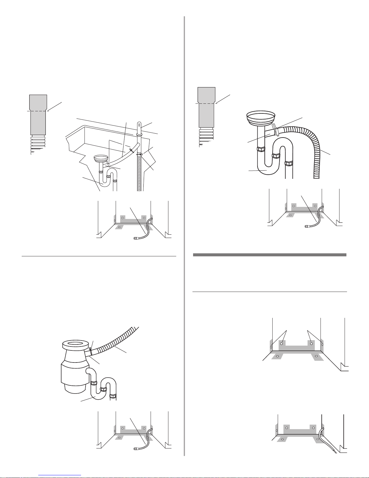
Option 3: Waste disposer – no air gap:
1. Remove the disposer knockout plug. Do not cut end of
drain hose.
2. Attach drain hose to disposer inlet with large springtype clamp.
This connection must be before the drain trap and at
least 20" (50.8 cm) above the floor where dishwasher
will be installed. It is recommended that the drain hose
be looped up and securely fastened to the underside of
the counter.
3. Insert drain hose
through hole cut in
cabinet to the front
center of opening where
drain connection will be
made.
drain hose
large spring-type
clamp
disposer
inlet
drain trap
Option 4: No waste disposer – no air gap:
1. Cut end of drain hose if needed (do not cut ribbed
section).
2. Attach drain hose to waste tee with 1-1/2" to 2"
(3.8 to 5 cm) screw-type clamp*.
This connection must be before the drain trap and at
least 20" (50.8 cm) above the floor where dishwasher
will be installed. It is recommended that the drain hose
be looped up and securely fastened to the underside of
the counter.
3. Insert drain hose
through hole cut in
cabinet to the front
center of opening where
drain connection will be
made.
* Parts available from local plumbing supply stores
drain
hose
waste
tee
drain trap
screw-type clamp
drain hose –
cut here if needed
Option 2: No waste disposer – with air gap:
1. Cut end of drain hose if needed (do not cut ribbed
section).
2. Attach drain hose to air gap with large spring-type
clamp. If the drain hose was cut, use a 1-1/2" to 2"
(3.8 to 5 cm) screw-type clamp*.
3. Use a rubber hose connector* with spring or screwtype clamps* to connect air gap to waste tee.
This connection must be before the drain trap and at
least 20" (50.8 cm) above the floor where dishwasher
will be installed.
4. Insert drain hose
through hole cut in
cabinet to the front
center of opening where
drain connection will be
made.
* Parts available from local plumbing supply stores
drain hose –
cut here if needed
drain
hose
large
spring-type
clamp
air gap
rubber hose
connector
spring or
screw-type
clamps
waste
tee
drain trap
drain hose
drain hose
drain hose
8
Option 2: Power supply cord method:
NOTE: A mating, three prong, ground-type wall receptacle
is required in a cabinet next to the dishwasher opening.
1. Drill a 1-1/2"
(3.8 cm) hole in
the cabinet rear
or side. Preferred
and optional
locations are
shown.
2. Wood cabinet:
Sand hole until
smooth.
Metal cabinet: Cover hole with grommet (Part No.
302797) included with power supply cord kit.
Install the water line
Helpful Tip: Routing the water line through the left side
of cabinet opening will make water connection easier.
1. Drill a minimum 1/2" (1.3 cm) hole in the cabinet side,
rear or floor. Preferred and optional locations are
shown.
2. Measure overall length
of copper tubing
required.
3. Attach copper tubing
to the water line with a
manual shutoff valve.
4. Slowly feed copper
tubing through hole in
cabinet. Copper tubing will bend and kink easily, so be
gentle. The copper tubing should be far enough into the
cabinet opening to connect it to dishwasher inlet on the
front left of the dishwasher.
5. Turn water shutoff valve to “ON” position. Flush water
into a shallow pan to get rid of particles that may clog
the inlet valve.
6. Turn shutoff valve to “OFF” position.
Option 1: Waste disposer – with air gap:
1. Remove the disposer knockout plug. Cut end of drain
hose if needed (do not cut ribbed section).
2. Attach drain hose to air gap with large spring-type
clamp. If the drain hose was cut, use a 1-1/2" to 2"
(3.8 to 5 cm) screw-type clamp*.
3. Use a rubber hose connector* with spring or screwtype clamps* to connect air gap to disposer inlet.
This connection must be before the drain trap and at
least 20" (50.8 cm) above the floor where dishwasher
will be installed.
4. Insert drain hose
through hole cut in
cabinet to the front
center of opening where
drain connection will be
made.
* Parts available from local plumbing supply stores
copper
tubing
drain
hose
large
spring-type
clamp
air gap
rubber hose
connector
disposer
inlet
drain trap
drain hose –
cut here if needed
spring or
screw-type
clamps
preferred
locations
optional
locations
optional
locations
preferred
locations
Install the drain hose
IMPORTANT: Always use a new drain hose.
1. Drill a 1-1/2" (3.8 cm)
diameter hole in
cabinet wall or floor on
the side of the opening
closest to the sink.
2. Connect drain hose to
waste tee or waste disposer using one of the following
methods:
• Option 1, Waste disposer – with air gap
• Option 2, No waste disposer – with air gap
• Option 3, Waste disposer – no air gap*
• Option 4, No waste disposer – no air gap*
*an air gap is recommended
Helpful Tip: To reduce the vibration of the hose, keep
the hose away from the floor and the edge of the hole
where it passes through the cabinet.
drain hose
9
Option 4: No waste disposer – no air gap:
1. Cut end of drain hose if needed (do not cut ribbed
section).
2. Attach drain hose to waste tee with 1-1/2" to 2"
(3.8 to 5 cm) screw-type clamp*.
This connection must be before the drain trap and at
least 20" (50.8 cm) above the floor where dishwasher
will be installed. It is recommended that the drain hose
be looped up and securely fastened to the underside of
the counter.
3. Insert drain hose
through hole cut in
cabinet to the front
center of opening where
drain connection will be
made.
* Parts available from local plumbing supply stores
1. Put corner posts from packaging behind dishwasher.
Grasp sides of dishwasher door frame and put
dishwasher on its back, resting on top of the corner
posts.
Prepare dishwasher
drain
hose
waste
tee
drain trap
screw-type clamp
drain hose –
cut here if needed
Option 2: No waste disposer – with air gap:
1. Cut end of drain hose if needed (do not cut ribbed
section).
2. Attach drain hose to air gap with large spring-type
clamp. If the drain hose was cut, use a 1-1/2" to 2"
(3.8 to 5 cm) screw-type clamp*.
3. Use a rubber hose connector* with spring or screwtype clamps* to connect air gap to waste tee.
This connection must be before the drain trap and at
least 20" (50.8 cm) above the floor where dishwasher
will be installed.
4. Insert drain hose
through hole cut in
cabinet to the front
center of opening where
drain connection will be
made.
* Parts available from local plumbing supply stores
Option 3: Waste disposer – no air gap:
1. Remove the disposer knockout plug. Do not cut end of
drain hose.
2. Attach drain hose to disposer inlet with large springtype clamp.
This connection must be before the drain trap and at
least 20" (50.8 cm) above the floor where dishwasher
will be installed. It is recommended that the drain hose
be looped up and securely fastened to the underside of
the counter.
3. Insert drain hose
through hole cut in
cabinet to the front
center of opening where
drain connection will be
made.
drain hose –
cut here if needed
drain
hose
large
spring-type
clamp
air gap
rubber hose
connector
spring or
screw-type
clamps
waste
tee
drain trap
drain hose
large spring-type
clamp
disposer
inlet
drain trap
drain hose
drain hose
drain hose
WARNING
Tip Over Hazard
Do not use dishwasher until completely installed.
Do not push down on open door.
Doing so can result in serious injury or cuts.
WARNING
Excessive Weight Hazard
Use two or more people to move and install dishwasher.
Failure to do so can result in back or other injury.
10
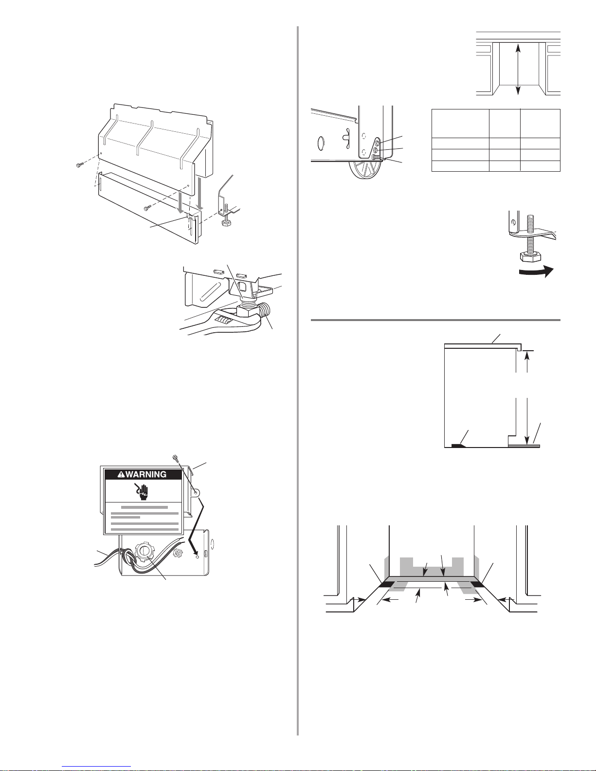
8. Measure height of cabinet opening
from underside of countertop to
floor where dishwasher will be
installed (you need the lowest
point). Check chart for that height
opening. Put wheels in the required
position.
9. Turn both front leveler legs to the same
height.
If the minimum cutout height is less than
34" (86.4 cm), the rear wheels can be
removed for additional clearance. This will
allow the dishwasher to fit into a 33-7/8"
(86 cm) high cutout, but the dishwasher
will be more difficult to move into
position. If the wheels are removed,
protect the floor when moving the dishwasher.
If you have built-up floors
1. Measure height of opening
from underside of
countertop to built-up
floor. If the height is at
least 33-3/4" (85.7 cm), the
dishwasher will fit into the
opening without
modification to the
countertop or flooring.
2. Put wheels in position 1
and turn the front leveler
legs up all the way.
3. Add shims as needed in the area shown to bring
dishwasher up to proper height.
NOTE: Shims must be securely attached to floor to
prevent their movement when the dishwasher is
operated.
1
2
3
10
5
0
Number of
turns on
front leg
Wheel
position
34" (86.4 cm)
34-1/4" (87 cm)
34-1/2" (87.6 cm)
1
2
3
Minimum
cutout height
wheel
front leg
2"
(5.1 cm)
6"
(15.2 cm)
2-3/4"
(7.0 cm)
2-3/4"
(7.0 cm)
shim
shim
shim
33-3/4"
(85.7 cm)
min.
countertop
built-up
floor
2. Remove two screws attaching access panel and lower
panel to dishwasher using a 1/4" hex socket, nut driver
or Phillips screwdriver.
3. Remove panels and set panels aside on a protective
surface.
4. Check that grounding clip is attached to the lower
panel.
5. Apply Teflon
®
tape or pipe
joint compound to 90° elbow
fitting and connect fitting to
water inlet valve.
6. Tighten elbow until snug, and
be sure that it faces to the
rear.
7. Remove terminal box cover. Pull appliance wires
through hole in terminal box. Do not untie the knot in
the wires.
– If you are direct wiring: install a U.L.-listed/CSA-
certified clamp connector to the terminal box. If using
conduit, use a U.L.-listed/CSA-certified conduit
connector.
– If you are installing a power supply cord kit, do so
now, following kit instructions.
lower
panel
access
panel
grounding
clip
water inlet valve
elbow
Helpful Tip: Put cardboard under dishwasher until it is
installed in cabinet opening. The cardboard will help
protect floor covering during installation.
dishwasher
wires
cable clamp connector
terminal
box cover
11
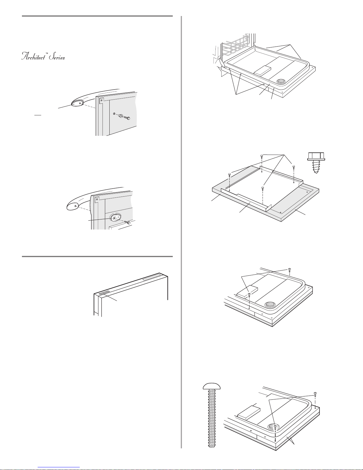
Top vented models
NOTE: Features on your
dishwasher may differ
from model shown.
Option 1:
For Top vented models with a factory-supplied stainless or
painted full front panel:
1. Remove the carton containing the factory-supplied full
front panel.
2. Remove the handle package from the front of the
shipping base.
3. Remove the inner panel from the door.
4. With a TORX
®
screwdriver, remove three screws from
both sides of the door. Hold the inner panel up while
removing the screws.
align top edges
2 screws
10. Install the two #8-18 x 1-3/8" screws from the literature
package in the top corners of the door.
11. Align the top edge of the full front panel with the top
edge of the console and secure corner screws.
12. Tighten the two screws installed in Step 9.
13. Reinstall and tighten the remaining screws in the inner
panel.
5. Gently set panel aside.
NOTE: Some models have 4 screws per side.
6. Lay the factory-supplied full front panel face down on a
protective non-scratching surface.
7. Place the inner panel on the back of the full front panel
as shown and attach, using the four #10-16 x 3/8" screws
in the literature package.
8. Attach the factory-supplied full front panel, inner panel,
and handle assembly to the door.
9. Reinstall the two uppermost screws into the inner panel,
do not tighten completely. This will hold the full front
panel in place on the door frame.
top of panel
Install the door handle (on some models)
IMPORTANT: Do not scratch the front panel during this
procedure.
1. Remove the Architect™ Series handle, plastic washers
and two screws from handle package.
2. Attach the handle to the factory-supplied full front panel
as shown.
do not remove screw.
screws
4 screws
full front panel
inner door panel
2 screws
screws
inner
door
panel
1. Remove the Pro Line™ Series handle and two screws
from handle package.
2. Make sure plastic spacers are still attached to the door.
3. Attach the handle to the factory-supplied full front panel
as shown.
Pro Line
™
Series
plastic spacers
film that is
not
to be
removed
Install door panel (on some models)
top vent
12
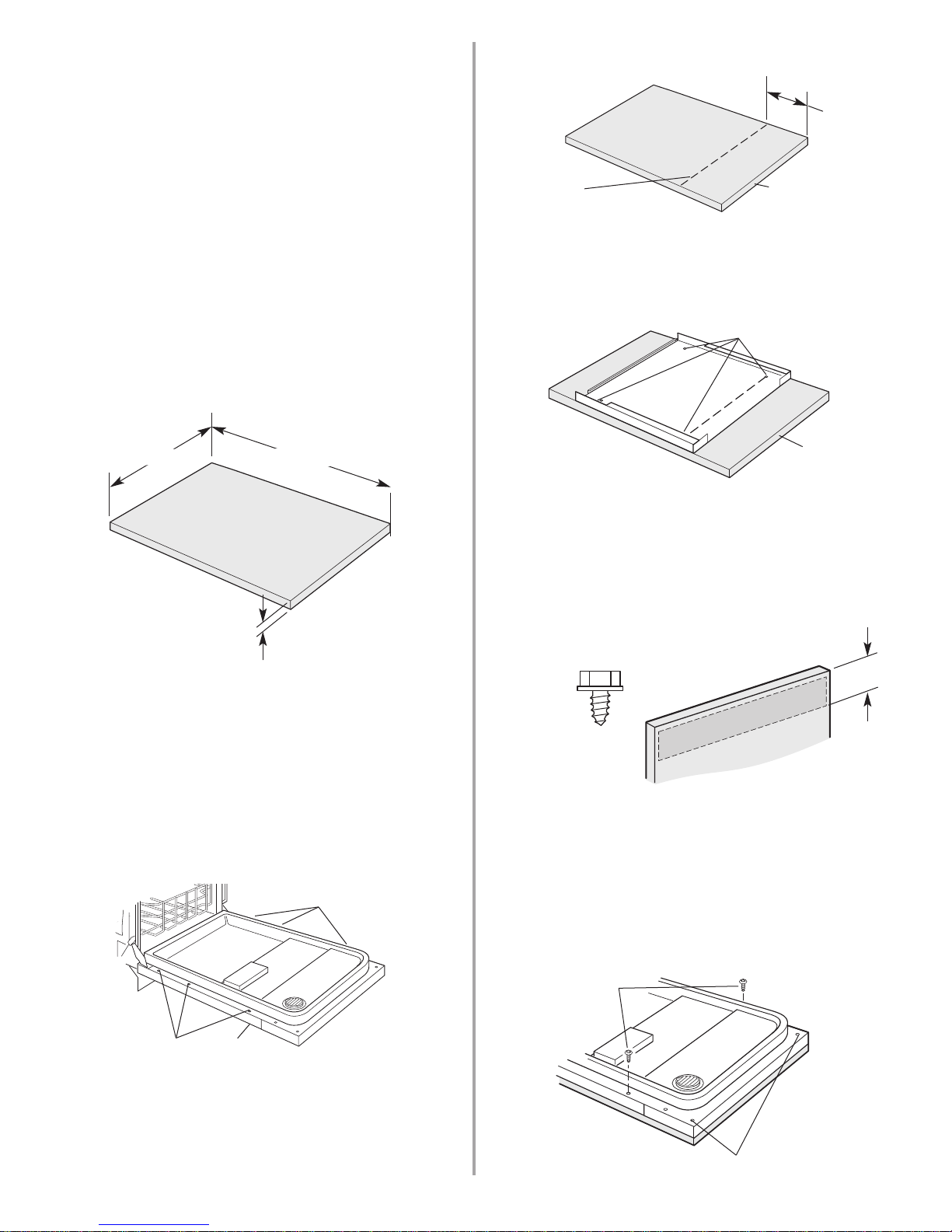
Option 2:
Top vented models with a custom full front panel.
NOTE: The handle for the custom panel is not included.
IMPORTANT: If the handle is attached from the back of the
custom panel, the screw heads must be flush with the
panel. If the handle is attached to the front of the custom
panel, the screw lengths cannot exceed the panel
thickness. For more information on KitchenAid custom
handle selection, refer to the KitchenAid Catalog, visit
www.kitchenaid.com, or call 1-800-422-1230.
NOTE: A custom full front panel must weigh no more than
16 pounds (7.3 kg) and must be made to specific
dimensions. It is recommended that a cabinetmaker cut the
custom panel because of the precise dimensions needed.
NOTE: All mounting hardware supplied are for a 3/4"
(19.1 mm) thick wood panel. If a thinner wood panel, or
materials other than wood are used, it is the consumer's
responsibility to obtain the proper length screws and
adjust the pilot holes accordingly.
IMPORTANT: Use a moisture resistant sealer on both sides
and all edges of the panel to protect it from humidity.
1. Remove the inner panel from the door.
2. With a TORX
®
screwdriver, remove three screws from
both sides of the door.
3. Hold the inner panel up while removing the screws.
4. Gently set panel aside.
NOTE: Some models have four screws per side.
5. Lay the custom full front panel face down on a
protective, non-scratching surface.
9-29/32"
(25.2 cm)
mark line
top
6. Measure 9-29/32" (25.2 cm) from top of panel and mark
a line on the back of panel.
7. Place the inner panel on the back of the custom panel so
that the top holes in the inner panel are on the line, and
the panels are centered side to side.
8. Mark all 4 holes, remove inner panel and drill 3/32" pilot
holes 1/2" (13 mm) deep.
mark pilot holes
top
9. Place the inner panel on the back of the custom panel
as shown.
10. Attach with the four #10-16 x 3/8" hex head screws
from the literature package.
11. Attach the handle. The handle should be centered on
the front of the custom panel in the area shown.
IMPORTANT: Screw heads must be flush with back of
custom panel.
6"
(15.2 cm)
hex head
screw
12. Attach the custom panel, inner panel, and handle
assembly to the door.
13. Reinstall the two upper most screws into the inner
panel, do not tighten completely. This will hold the
custom panel assembly in place on the door frame.
14. Align the top edge of the custom panel with the top of
the console.
15. Mark two holes on the custom panel through the holes
in the upper corners of the inner panel and console, as
shown.
mark through these holes
2 screws
*30-3/16" (76.7 cm)
3/4" (19.1 mm)
custom panel
dimensions
23-1/2" (59.7 cm)
*This dimension is for 4" (10.2 cm) toe kick. If the installation
needs a higher toe kick, adjust the height of the wood panel
accordingly. Not recommended for toe kicks greater than 6"
(15.2 cm).
3 screws
3 screws
inner door
panel
13
16. Remove the two screws and the custom panel and
drill two – 3/32" pilot holes 1/2" (13 mm) deep,
where marked.
17. Reattach the custom panel, inner panel and handle
assembly to the door.
18. Reinstall the two upper most screws into the inner
panel. Do not tighten completely. This will hold the
custom panel assembly in place on the door frame.
19. Install the two #8-18 x 1-3/8" screws from the literature
package in the top corners of the door.
20. Align the top edge of the full front panel with the top
edge of the console and secure corner screws.Tighten
the two remaining screws installed in Step 18. Reinstall
and tighten the remaining screws in the inner panel.
align top edges
Front vented models
If the front of your dishwasher
looks like this, it is designed
for a custom panel.
Model shown – KUDS01D_SP.
All other models require an
accessory option to attach
custom panels.
NOTE: A custom front panel
must weigh no more than 14
pounds (6.3 kg) and must be
made to these dimensions. It is recommended that a
cabinetmaker cut the custom panel because of precise
dimensions needed.
IMPORTANT: Use a moisture resistant sealer on both sides
and all edges of panel to protect from humidity.
front
vent
1/8" (3.2 mm)
1/8"
(3.2 mm)
front
23-3/8"
(59.4 cm)
Front View Side View
3/4"
(1.9 cm)
*25-29/32"
(65.8 cm)
1. To install the custom panel, first remove metal front
panel from door.
2. With TORX
®
screwdriver, remove lower three screws
from both sides of inner door.
3. Hold panel up while removing screws.
NOTE: Some models have four screws per side.
4. Lay metal panel on back of custom panel.
5. Align top edge of custom panel with top edge of metal
panel, and center it side to side.
6. Mark the position of four inner holes on custom panel.
7. Drill four 3/32" holes in custom panel at marked
positions.
8. Attach custom panel to metal panel with four #10 x 1/2"
wood screws (not supplied). (If the custom panel is less
than 3/4" (1.9 cm) thick where the screws are attached,
shorter screws may be required.)
9. Reattach the assembled panels to dishwasher door.
2 screws
1-3/8"
screw
3 screws
3 screws
front panel
*This dimension is for 4" (10.2 cm) toe kick. If the installation needs a
higher toe kick, adjust the height of the wood panel accordingly. Not
recommended for toe kicks greater than 6" (15.2 cm).
NOTE: These dimensions are for frameless custom panel
models with a 4-inch (10.2 cm) console only.
custom panel
dimensions
4 inner holes
custom panel
metal panel
14
5. Push bracket into slot on the side of dishwasher, and
bend tab in towards the side of the dishwasher so that
it keeps the bracket in place.
NOTE: Do not attach the dishwasher, this will be done
later.
Move dishwasher into cabinet opening
1. Grasp the sides of the dishwasher
at the edges of the door panel.
2. Tilt dishwasher backwards on
wheels and move dishwasher close
to cabinet opening. Do not push on
the front of the panel or on the
console—they may dent.
3. If dishwasher has a power supply
cord, insert power supply cord into hole cut into
cabinet.
If using direct wire, check that it is on the right front
side of opening.
4. Check that water line is on the left side of opening and
drain hose is near the center of the hole in the cabinet.
5. Slowly move dishwasher completely into cabinet
opening. Do not kink or pinch copper tubing, drain
hose, power supply cord or direct wire between
dishwasher and cabinet.
Helpful Tip: Once the dishwasher is in position, you
may have to support the front of the dishwasher by
raising, lowering or shimming front feet.
6. Remove cardboard from under dishwasher.
NOTE: It is all right if dishwasher fits tightly into cabinet
opening. Do not remove insulation blanket —the blanket
reduces the sound level.
score
line
plastic
button
bend
tabs
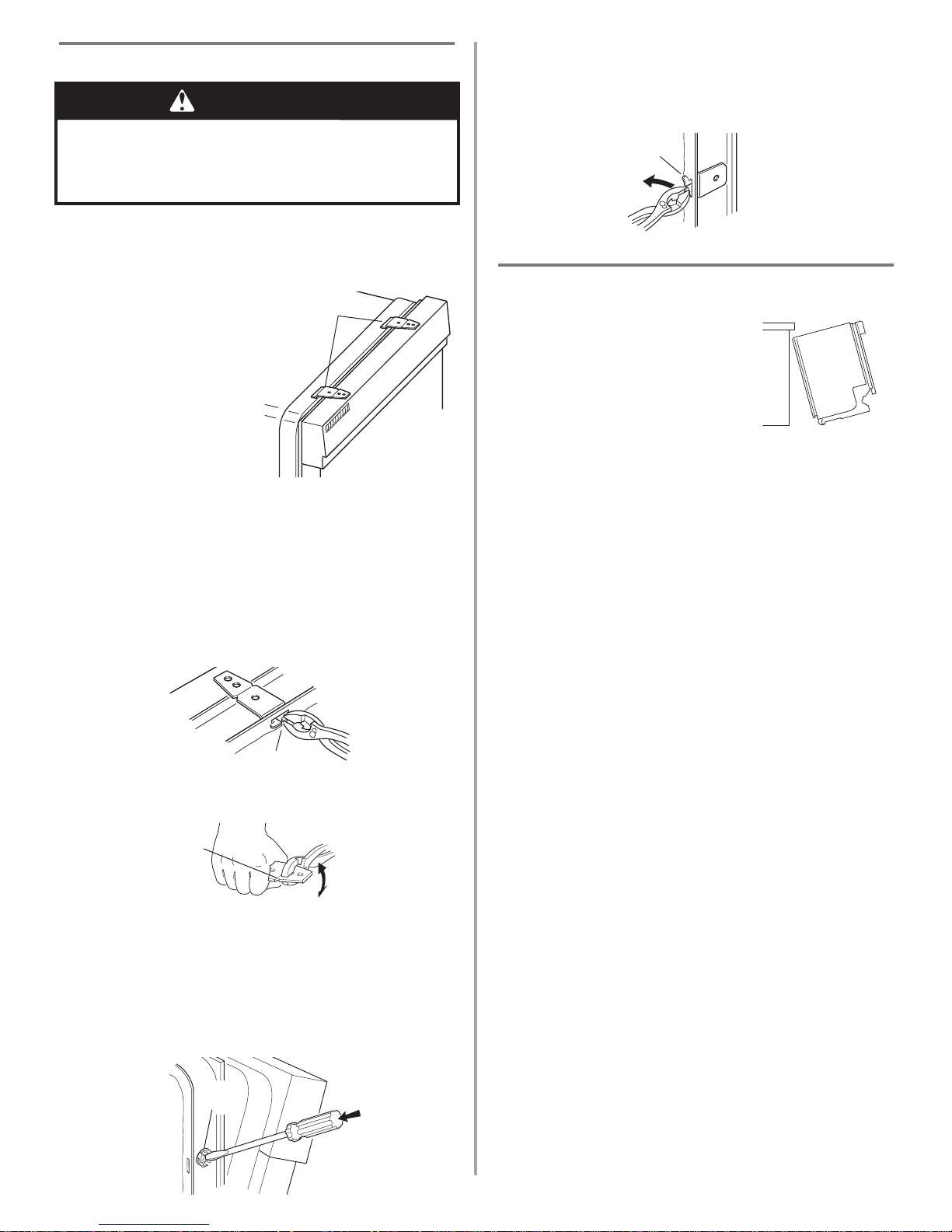
Choose attachment option
Using two or more people, stand the dishwasher up.
Option 1: Countertop attachment
The dishwasher must be
secured to the cabinet. There
are two brackets on top of the
dishwasher that can be
attached to the countertop if it
is wood, laminate or other
similar surfaces. If this is not
possible, the brackets may be
moved to the sides of the
dishwasher.
NOTE: Do not attach the
dishwasher, this will be done
later.
brackets
front vent
model shown
Option 2: Dishwasher side attachment
(for marble, granite or other hard surface
countertop)
1. To remove the brackets from the top, flatten tab at back
of brackets with pliers, and pull the brackets out of the
slots.
tabs
2. Break off the end of the bracket along the scored line.
3. Open dishwasher door and place towel over pump
assembly and spray arm of dishwasher. This will
prevent screws from falling into pump area when
securing dishwasher to cabinet.
4. Push the plastic buttons out of the side of the tub.
NOTE: Save the buttons to cover the holes after
dishwasher is installed.
WARNING
Excessive Weight Hazard
Use two or more people to move and install dishwasher.
Failure to do so can result in back or other injury.
15
4. Repeat for other side of dishwasher.
NOTE: Shims must be securely attached to floor to prevent
their movement when the dishwasher is operated.
5. Place level against top front
opening of tub. Check that
dishwasher is level from side to
side. If dishwasher is not level,
adjust front legs up or down until
dishwasher is level.
Make Electrical Connection
Check “Electrical requirements” section.
You need to:
• have the correct electrical supply and recommended
grounding method.
If you are:
•direct wiring, use Option 1
• using a power supply cord, use Option 2
Option 1: Direct wire method
1. Route direct wire so that it does not touch dishwasher
motor or lower part of dishwasher tub.
2. Pull direct wire through hole in terminal box.
Helpful Tip:
• Select the proper size twist-on
connectors to connect your household
wiring to 16-gauge dishwasher wiring.
• Insert wire ends into twist-on
connector. Do not pre-twist bare wire.
• Twist connector.
• Gently tug on wires to be sure both
are secured.
3. Connect the wires as follows using twist-on connectors
sized to connect direct wire to 16-gauge dishwasher
wire:
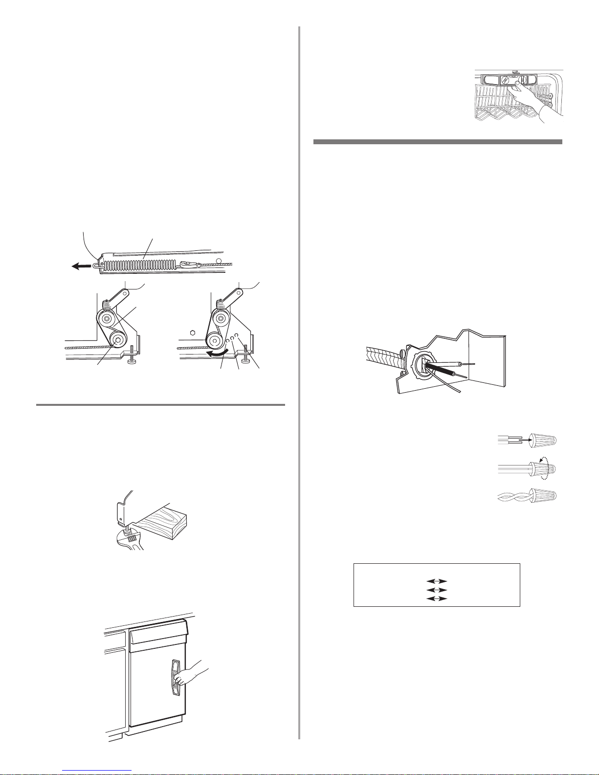
Check door spring tension
1. With another person holding the dishwasher to prevent
it from tipping, open and close the door a few times. If
the door closes or falls open under its own weight, the
door tension will need to be adjusted.
2. To adjust the door spring tension, unhook the spring
from the rear leg of dishwasher.
3. With a 5/16" nut driver or hex socket, remove the screw
from the tensioner.
4. The screw can be put into one of three holes , ,
in front leg of dishwasher. If the door closes by itself,
move the tensioner to a higher number hole and
replace screw. When door is unlatched, if it opens by
itself, move tensioner to a lower numbered hole and
replace screw.
5. Re-attach door spring to rear leg. Tensioners on both
sides of dishwasher should be secured at same holes.
Level the dishwasher
1. Align front of dishwasher door panel with cabinet
doors. You may need to adjust alignment to be even
with your cabinets.
Helpful Tip: Prop up one side of frame to hold
dishwasher up off floor when adjusting front legs.
2. Check that leveling legs are firmly against the floor.
3. Close and latch the door, and place level against the
front panel. Check that dishwasher is plumb. If needed,
adjust leveling leg or add shims under rear wheel until
dishwasher is plumb.
screw
tensioner
spring
Terminal box wire:
white
black
ground connector
Power supply wire:
white
black
ground wire
16
Option 2: Power supply cord method
1. Plug into a grounded 3 prong outlet.
2. Check that power supply cord does not touch
dishwasher motor or lower part of dishwasher tub.
Connect to water supply
Helpful Tip:
Compression fittings:
a. Slide nut onto copper tubing about 1" (2.5 cm).
b. Slide ferrule onto the tubing. Do not position ferrule
on the end of the tubing.
c. Put the tubing into the elbow as far as it will go.
d. Slide the nut and ferrule forward and start the nut
onto the elbow threads. Be gentle when handling
and positioning the copper tubing, it bends and kinks
easily.
1. To prevent vibration during operation, route the water
supply line so that it does not touch the dishwasher
base, frame or motor.
2. With copper tubing pushed into compression fitting as
far as it will go, use a wrench and tighten compression
fitting nut to elbow on water inlet valve.
3. Place paper towel under elbow. Turn on water supply
and check for leaks.
nut
ferrule
elbow
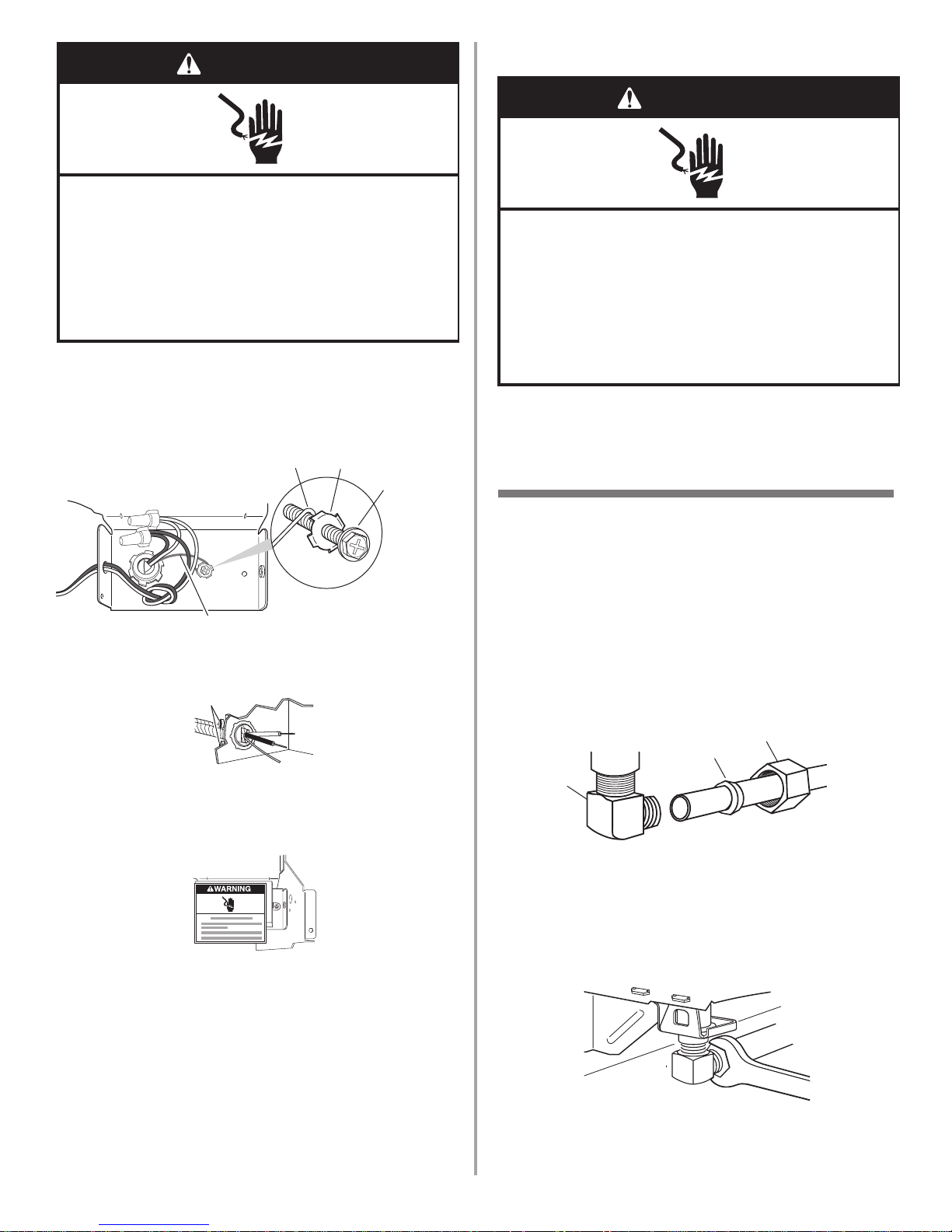
4. Form bare ground wire into a U-shaped hook. Wrap
ground wire hook clockwise around ground connector
and under the washer.
5. Securely tighten ground connector. Do not untie knot in
the wires.
6. Tighten clamp connector or conduit connector screws.
7. Reinstall terminal box cover with wires inside terminal
box.
The cover must be outside the box on the left side.
8. Make sure no wires are pinched by cover.
ground wire
washer
ground
connector
ground wire
screws
WARNING
Electrical Shock Hazard
Electrically ground dishwasher.
Connect ground wire to green ground connector in
terminal box.
Do not use an extension cord.
Failure to follow these instructions can result in death,
fire, or electrical shock.
WARNING
Electrical Shock Hazard
Plug into a grounded 3 prong outlet.
Do not remove ground prong.
Do not use an adapter.
Do not use an extension cord.
Failure to follow these instructions can result in death,
fire, or electrical shock.
17
Secure dishwasher in cabinet opening
1. If you have not already done so, open dishwasher door
and place towel over pump assembly and spray arm of
dishwasher. This will prevent screws from falling into
pump area when securing dishwasher to countertop.
2. Check that dishwasher is still level and centered side to
side in the opening.
3. Secure dishwasher to countertop or sides of cabinet
with two, #10 x 1/2" Phillips-head screws. The
dishwasher must be secured to keep it from tipping
when door is opened. Do not drop screws into bottom
of dishwasher.
4. Open door about 3 inches (7.6 cm) and check that space
between inner door and tub is equal on both sides. If
spacing is not equal, loosen bracket screws and shift
tub. Tighten bracket screws.
5. Check that top of door does not contact screws,
brackets, or countertop. If it does, dishwasher must be
lowered and re-leveled.
6. If securing to sides of cabinet, replace the plastic
buttons.
7. Remove towel from dishwasher.
8. Reinstall the lower dishrack.
plastic
button
screw to countertop
screw to
side cabinet
OR
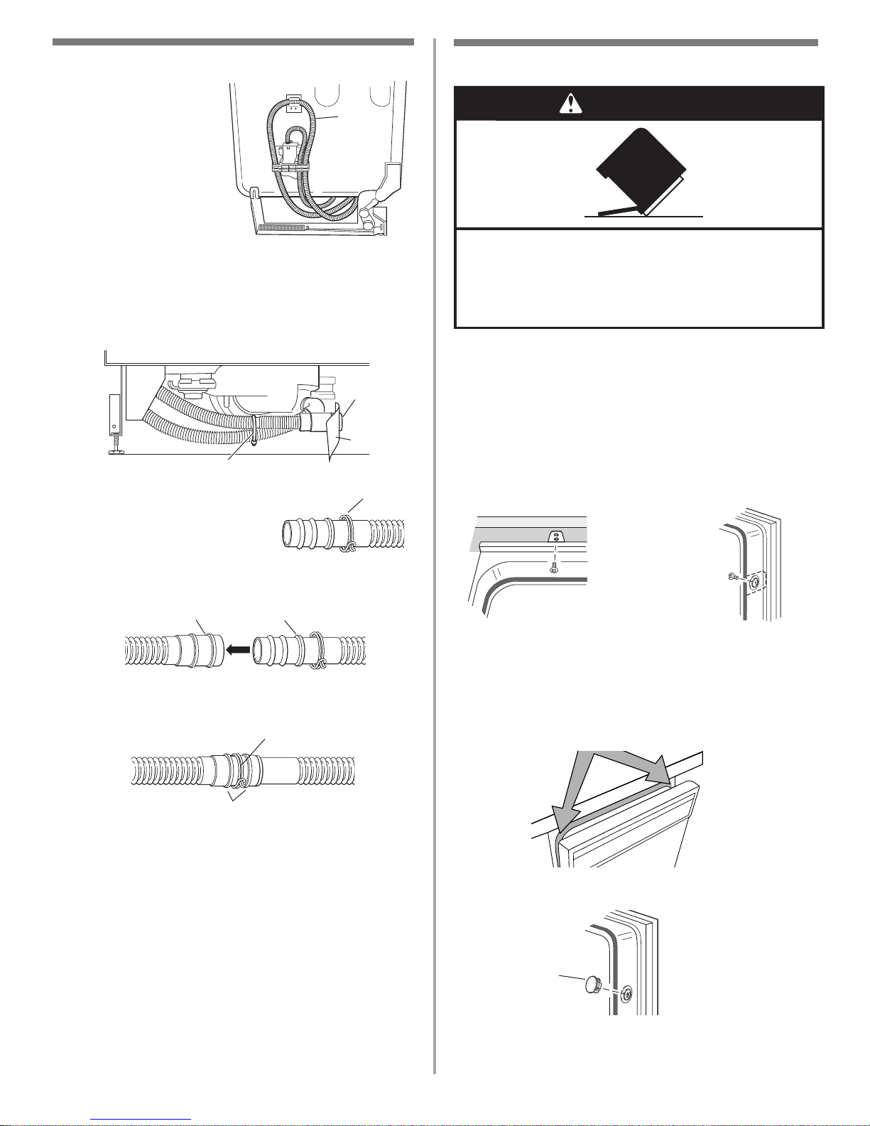
Connect to drain
1. To help minimize
vibration, route drain
hose to avoid contact
with motor, door springs,
water line, cabinet,
flooring or the edge of
the hole where it passes
through the cabinet.
2. Do not remove drain
loop from side of
dishwasher.
3. Place pan under end of drain hose. Pan will collect any
water in drain hose.
4. Remove plug and paper from drain connector.
NOTE: Cutting the zip tie holding the end of drain hose
in place may make maneuvering the drain hose easier
during installation.
5. Place the smaller drain hose
clamp onto the small end of the
drain hose.
6. Push the drain hose into the connector up to the stop
on the drain hose.
7. Use pliers to open clamp and slide clamp onto
connector between stops on connector as shown.
drain
loop
hose
clamp
stop
connector
hose clamp
stops
plug
zip tie
paper
WARNING
Tip Over Hazard
Do not use dishwasher until completely installed.
Do not push down on open door.
Doing so can result in serious injury or cuts.
 Loading...