


KBAU181V
KitchenAid KBAU181V, KBAU362V, KBAU272V, KBAU482V, KBAU482VSS00 User Manual
...
OUTDOOR ACCESS DOORS
Installation Instructions and Use & Care Guide
For questions about features, operation/performance, parts, accessories or service, call: 1-800-422-1230
or visit our website at www.kitchenaid.com
In Canada, call for assistance, installation and service, call: 1-800-807-6777
or visit our website at www.KitchenAid.ca
PORTES D’ACCÈS D’EXTÉRIEUR
Instructions d’installation et Guide d’utilisation et d’entretien
Au Canada, pour assistance, installation ou service composez le 1-800-807-6777 ou visitez notre site Web à.
www.KitchenAid.ca
Table of Contents/Table des matières.............................................................................2
Models/Modèles KBAU181V KBAU272T KBAU272V KBAU302T KBAU362T
KBAU362V KBAU482T KBAU482V KBAL181T KBAR181T
W10118096B

2
TABLE OF CONTENTS
OUTDOOR ACCESS DOORS SAFETY.........................................3
INSTALLATION REQUIREMENTS................................................3
Tools and Parts ............................................................................3
Product Dimensions.....................................................................4
Cabinet Cutout Dimensions.........................................................5
INSTALLATION INSTRUCTIONS..................................................7
Install Access Door - Style 1 (external hinge pin)........................7
Install Access Door - Style 2 (internal hinge)...............................7
Access Door Alignment - Style 2 Only.........................................7
Access Door Removal..................................................................8
18" (45.7 cm) Access Door Reversal - Style 2 Only ....................9
Attach Condiment Shelf - Styles 1 and 2 ..................................10
ACCESS DOORS CARE...............................................................11
General Cleaning........................................................................11
ASSISTANCE OR SERVICE.........................................................11
In the U.S.A. ...............................................................................11
In Canada ...................................................................................11
WARRANTY ..................................................................................12
TABLE DES MATIÈRES
SÉCURITÉ DES PORTES D'ACCÈS D'EXTÉRIEUR..................14
EXIGENCES D'INSTALLATION...................................................14
Outillage et pièces......................................................................14
Dimensions du produit...............................................................15
Dimensions de l'ouverture à découper dans le placard............16
INSTRUCTIONS D’INSTALLATION.............................................18
Installation de la porte d'accès -
Style 1 (axe de charnière externe)..............................................18
Installation de la porte d'accès - Style 2 (charnière interne) .....18
Alignement de la porte d'accès - Style 2 uniquement ..............18
Dépose de la porte d'accès.......................................................19
Inversion de la porte d’accès de 18" (45,7 cm) - Style 2
uniquement.................................................................................20
Fixation de l’étagère à condiments – Styles 1 et 2....................21
ENTRETIEN DES PORTES D'ACCÈS.........................................22
Nettoyage général ......................................................................22
ASSISTANCE OU SERVICE.........................................................22
Au Canada..................................................................................22
GARANTIE.....................................................................................23
3
OUTDOOR ACCESS DOORS SAFETY
INSTALLATION REQUIREMENTS
Tools and Parts
Gather the required tools and parts before starting installation. Read and follow the instructions provided with any tools listed here.
Tools Needed
■ Tape measure
■ Short #2 Phillips screwdriver or a 90° screwdriver with a
#2 Phillips screw bit
■ #2 Phillips screwdriver
■ #3 Phillips screwdriver (optional - for door reverse only)
■ Level
Parts Needed
■ Screws (quantity and type to be determined by the
requirements of the cabinet material)
You can be killed or seriously injured if you don't immediately
You
can be killed or seriously injured if you don't
follow
All safety messages will tell you what the potential hazard is, tell you how to reduce the chance of injury, and tell you what can
happen if the instructions are not followed.
Your safety and the safety of others are very important.
We have provided many important safety messages in this manual and on your appliance. Always read and obey all safety
messages.
This is the safety alert symbol.
This symbol alerts you to potential hazards that can kill or hurt you and others.
All safety messages will follow the safety alert symbol and either the word “DANGER” or “WARNING.”
These words mean:
follow instructions.
instructions.
DANGER
WARNING
4
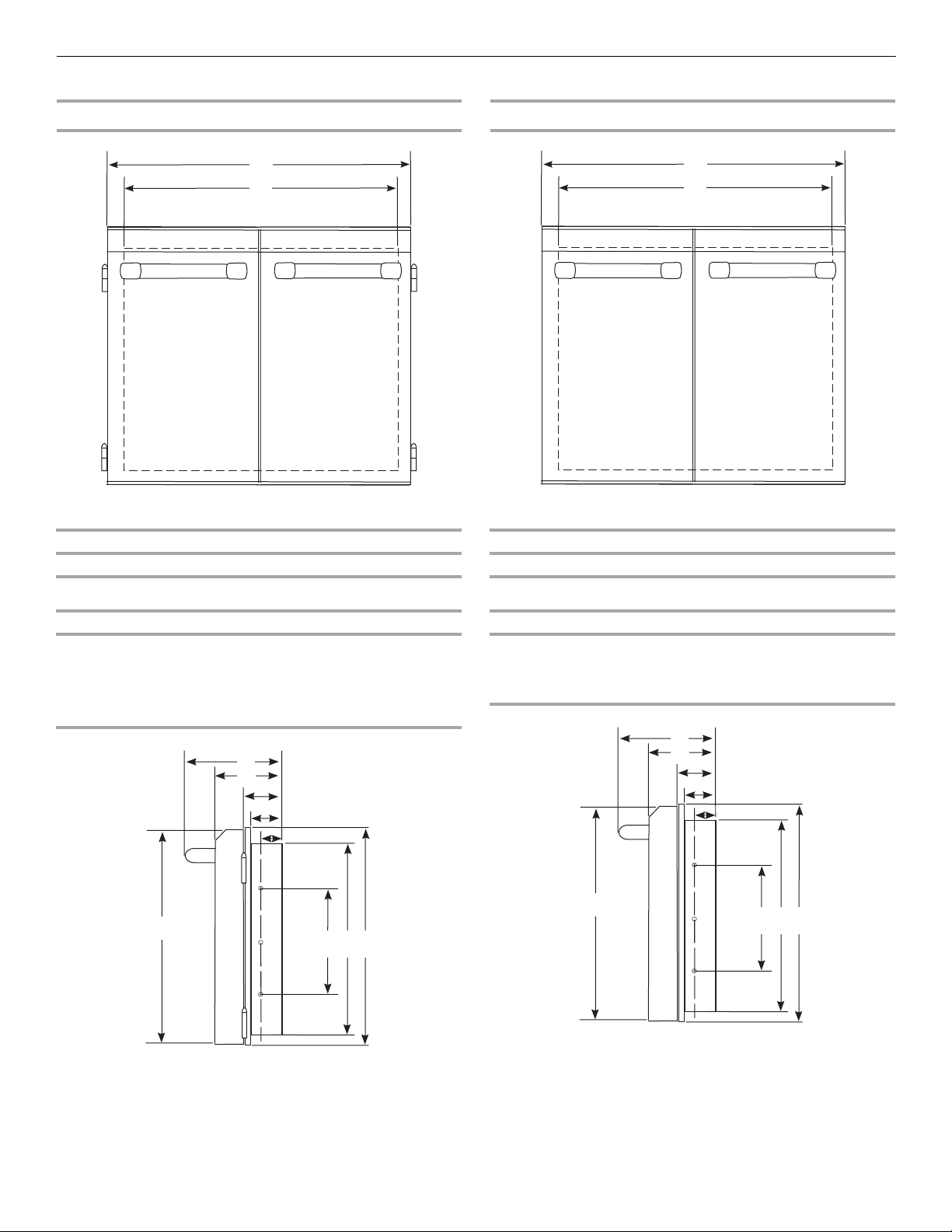
Product Dimensions
Access Door Style 1 (external hinge pin)
Single Access Doors
Double Access Doors
Access Door Style 2 (internal hinge)
Single Access Doors
Double Access Doors
A B (Mounting Frame)
18" (45.7 cm) 15¾" (39.9 cm)
A B (Mounting Frame)
27" (68.5 cm) 24¹³⁄₁₆" (63 cm)
30" (76.2 cm) 27¹³⁄₁₆" (70.7 cm)
36" (91.4 cm) 33¹³⁄₁₆" (85.9 cm)
48" (121.9 cm) 45¹³⁄₁₆" (116.4 cm)
A. 7⁵⁄₈" (19.4 cm)
B. 4³⁄₈" (11.3 cm)
C. 2" (5.1 cm)
D. 1⁵⁄₈" (4 cm)
E. 1" (2.5 cm)
F. 2 2 ⁵⁄₈" (57.4 cm)
G. 20³⁄₈" (51.6 cm)
H. 13³⁄₈" (34 cm)
I. 22³⁄₈" (56.7 cm)
B
A
C
D
E
I
F
G
H
B
A
A B (Mounting Frame)
18" (45.7 cm) 15¾" (39.9 cm)
A B (Mounting Frame)
27" (68.5 cm) 24¹³⁄₁₆" (63 cm)
36" (91.4 cm) 33¹³⁄₁₆" (85.9 cm)
48" (121.9 cm) 45¹³⁄₁₆" (116.4 cm)
A. 7⁵⁄₈" (19.4 cm)
B. 4³⁄₈" (11.3 cm)
C. 2" (5.1 cm)
D. 1⁵⁄₈" (4 cm)
E. 1" (2.5 cm)
F. 2 2 ⁵⁄₈" (57.4 cm)
G. 20³⁄₈" (51.6 cm)
H. 13³⁄₈" (34 cm)
I. 22³⁄₈" (56.7 cm)
B
A
C
D
E
I
F
G
H
B
A
5
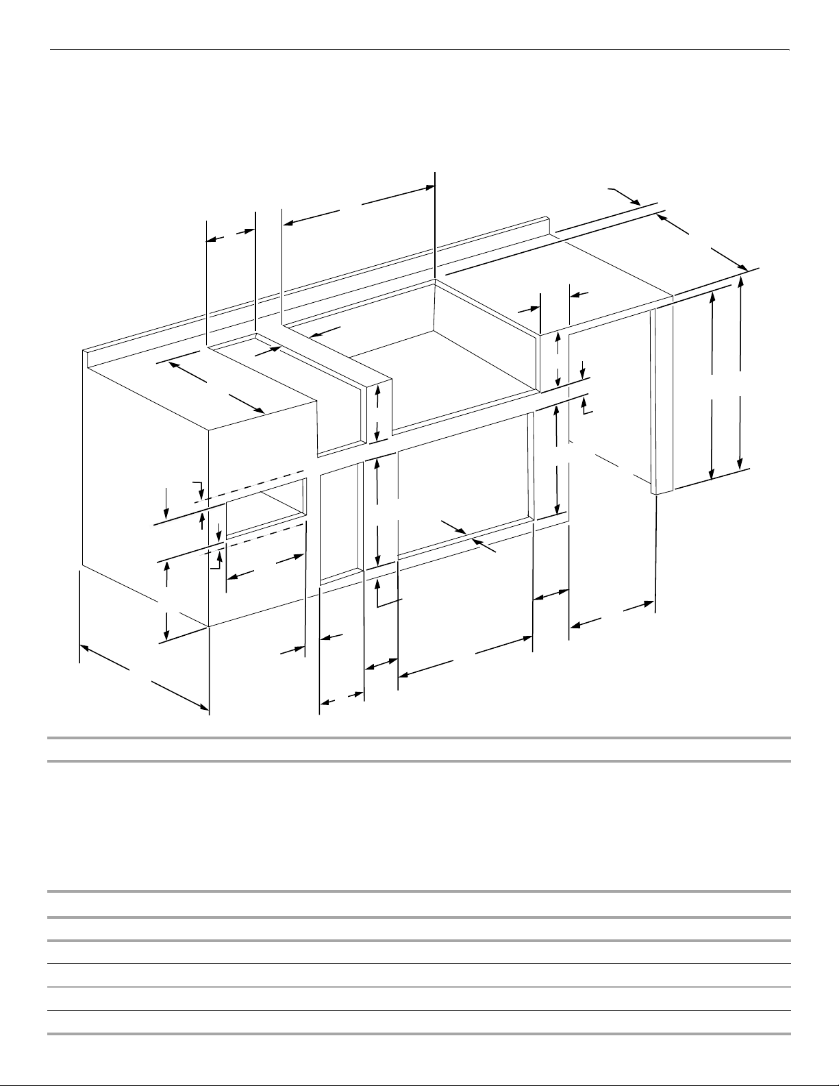
Cabinet Cutout Dimensions
The dimension chart and illustration below include cutout dimensions and minimum spacing requirements for all built-in outdoor
products. The illustration is for reference. The design of your cabinet layout can be personalized, but the dimensions for the cutouts and
minimum spacing must be followed.
Installation must conform to local codes.
C
E
D
H
A
G
K
K
F
K
B
J
D
E
20⁵⁄₈" (52.4 cm)
1¹⁄₂"
(3.8 cm) min.
3" (7.6 cm) min.
to open hood
2¹⁄₂" (6.4 cm) min.
12" (30.5 cm) min.
to any accessory
12" min.
to any
accessory
20⁷⁄₈" (53.0 cm)
9¹⁄₈"
(23.2 cm)
5"
(12.7 cm) min.
C
M
L
K
K
Grills or
Refreshment Centers
Side
or
Sear
Burners
Warming
Drawer
Access Doors
Refrigerator
or
Ice Maker
Utility
or
Trash
Drawer
Minimum Spacing Requirement Between Cutouts - Dimension K
Between 2 or more sets of Access Doors adjacent to each other:
K = 14" (35.6 cm) when 2 adjacent doors are opened to 90 degrees
K = 8" (20.3 cm) when 1 of the adjacent doors is opened to 90 degrees
Between a set of Access Doors and a Trash Drawer, Utility Drawer, Warming Drawer, Refrigerator, or Ice Maker:
K = 8" (20.3 cm) when 1 of the adjacent doors is opened to 90 degrees
Between a Trash Drawer, Utility Drawer, or Warming Drawer:
K = 3" (7.6 cm)
Cabinet Height and Depth Dimensions
Dimension A Minimum Dimension B Minimum
With outdoor refrigerator 37" (94.0 cm) 26" (66.0 cm)
Grill with insulated jacket 36½" (92.7 cm) 27" (68.6 cm)
Grill without insulated jacket 35½" (90.2 cm) 26" (66.0 cm)

6
*Dimension L is the minimum mounting surface area around the opening for mounting the optional door or drawers.
Cutout Dimensions - Built-in Grill
Grill Size Dimension C Dimension D Dimension E
27" (68.6 cm) 29⁵⁄₈" (75.2 cm) 10¾" (27.3 cm) 22⁷⁄₈" (58.1 cm)
36" (91.4 cm) 38⁵⁄₈" (98.1 cm) 10¾" (27.3 cm) 22⁷⁄₈" (58.1 cm)
48" (121.9 cm) 50⁵⁄₈" (128.6 cm) 10¾" (27.3 cm) 22⁷⁄₈" (58.1 cm)
Cutout Dimensions - Built-in Grill with Insulated Jacket
Grill Size Dimension C Dimension D Dimension E
27" (68.6 cm) 33" (83.8 cm) 11¾" (29.8 cm) 24" (61.0 cm)
36" (91.4 cm) 42" (106.7 cm) 11¾" (29.8 cm) 24" (61.0 cm)
48" (121.9 cm) 54" (137.2 cm) 11¾" (29.8 cm) 24" (61.0 cm)
Cutout Dimensions - Built-in Side Burner
Burner Position Dimension C Dimension D Dimension E
Front to Back 13½" (34.3 cm) 10¾" (27.3 cm) 22⁵⁄₈" (57.5 cm)
Side by Side 24½" (62.2 cm) 10¾" (27.3 cm) 16⁷⁄₈" (42.9 cm)
Cutout Dimensions - Built-in Sear Burner
Dimension C Dimension D Dimension E
13½" (34.3 cm) 10⁵⁄₈" (27.0 cm) 22¹¹⁄₁₆" (57.6 cm)
Cutout Dimensions - Built-in Refreshment Center
Dimension C Dimension D Dimension E
30½" (77.5 cm) 10¾" (27.3 cm) 23" (58.4 cm)
Cutout Dimensions - Built-in Access Doors
Door Size Dimension F Dimension L*
18" (45.7 cm) 16³⁄₁₆" (41.1 cm) 1½" (3.8 cm)
27" (68.6 cm) 25¹⁄₈" (63.8 cm) 1½" (3.8 cm)
30" (76.2 cm) 28¹⁄₈" (71.4 cm) 1½" (3.8 cm)
36" (91.4 cm) 34¹⁄₈" (86.7 cm) 1½" (3.8 cm)
48" (121.9 cm) 46¹⁄₈" (117.2 cm) 1½" (3.8 cm)
Cutout Dimensions - Outdoor Refrigerator
Dimension G Dimension H
24" (61.0 cm) 35¼" (89.5 cm)
Cutout Dimensions - Outdoor Ice Maker
Dimension G Dimension H
18" (45.7 cm) 34" (86.4 cm) min. to 34½" (87.6 cm) max.
7
*Dimension L is the minimum mounting surface area around the opening for mounting the optional door or drawers.
INSTALLATION INSTRUCTIONS
Install Access Door - Style 1
(external hinge pin)
1. Remove access doors from mounting frame by lifting each
door up and off the mounting frame hinge.
2. Install mounting frame flush to the face of the cabinet cutout.
Make sure the mounting frame is level.
3. Install screws (not supplied) into holes located on the
mounting frame.
4. Replace access doors by placing each door back on the
mounting frame hinges.
Install Access Door - Style 2 (internal hinge)
1. Install mounting frame flush to the face of the cabinet cutout.
2. Open doors.
3. Make sure the mounting frame is level and square to the
cabinet.
4. Install screws (not supplied) into holes located on the
mounting frame.
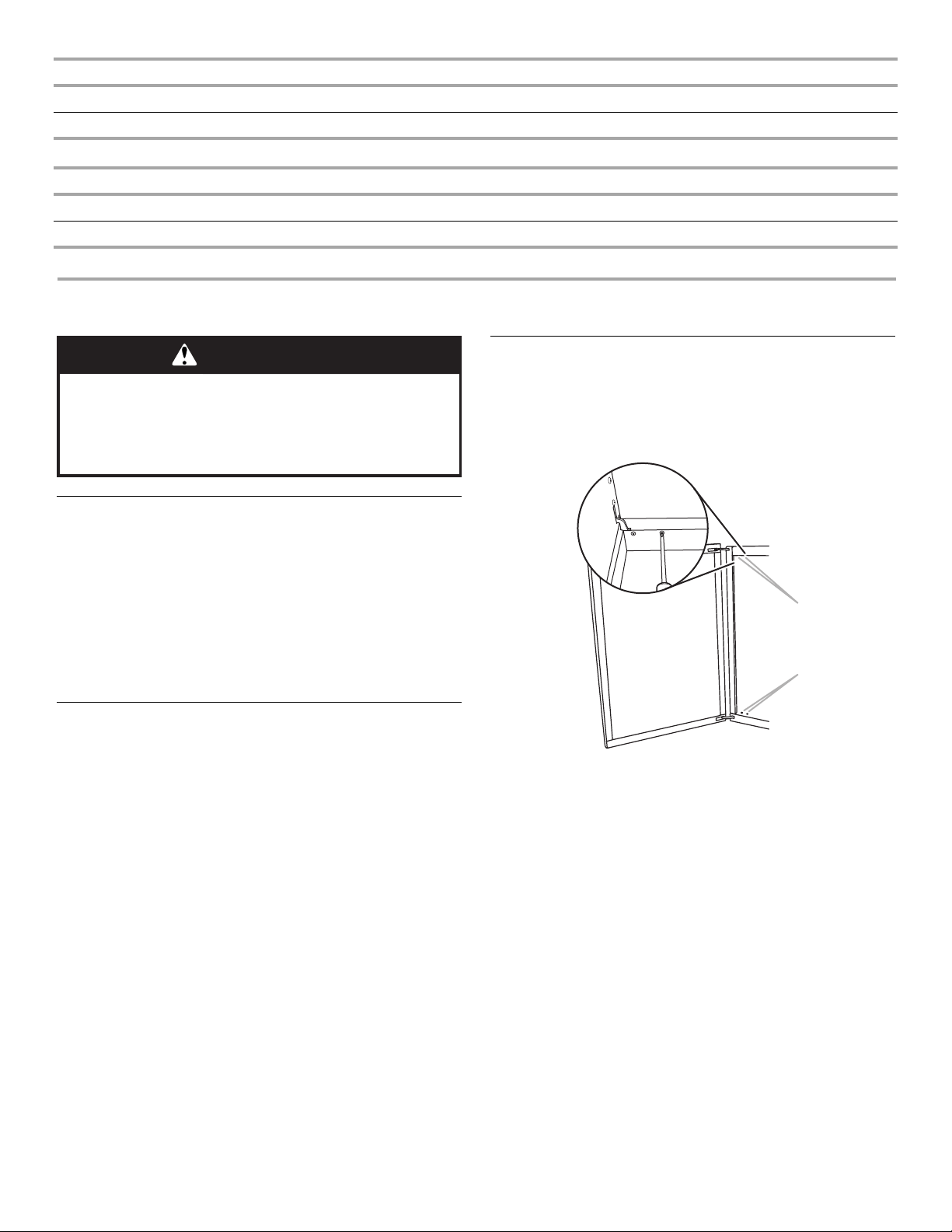
Access Door Alignment - Style 2 Only
Your access door(s) can be realigned if necessary.
1. Check door to determine alignment requirements.
2. Open the access door.
3. Locate and loosen the 4 door hinge mounting screws ½ turn.
4. Adjust the top or bottom of the door in the direction
necessary to align the door.
5. Tighten the 4 door hinge mounting screws.
6. Close the door and check alignment.
7. Readjust the door using steps 2 through 6 if necessary.
8. Repeat steps 1 through 7 on the other door if necessary.
Cutout Dimensions - Built-in Warming Drawer
Warming Drawer Size Dimension J
24" (61.0 cm) 22½" (57.2 cm)
Cutout Dimensions - Built-in Utility Drawer and Built-in Trash Drawer
Dimension M Dimension L*
12¼" (31.1 cm) 1½" (3.8 cm)
WARNING
Excessive Weight Hazard
Use two or more people to move and install
access doors.
Failure to do so can result in back or other injury.
A. Top door hinge mounting screws
(2 - underside of frame)
B. Bottom door hinge mounting screws (2)
A
B
8
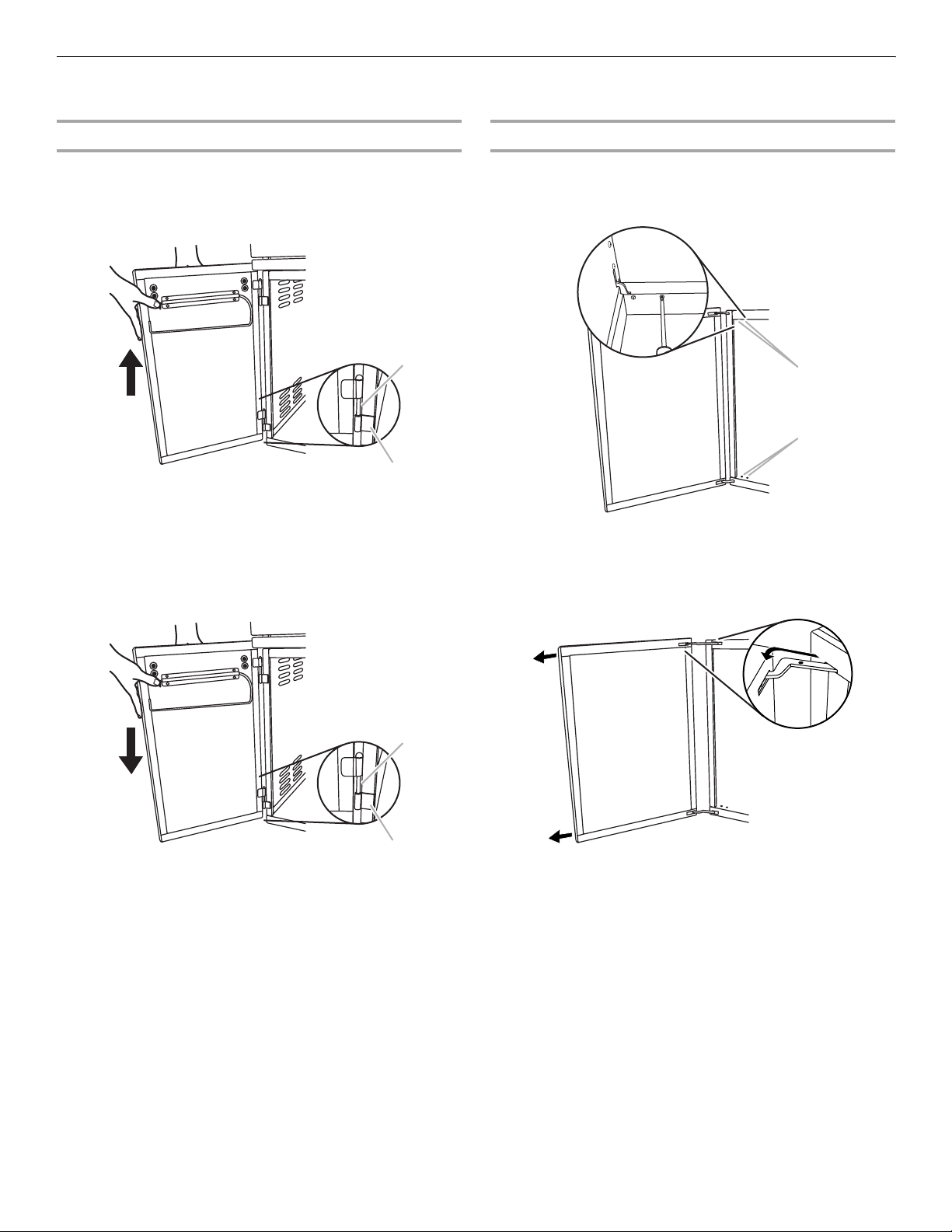
Access Door Removal
The access door(s) can be removed if necessary to gain access to the inside of the cabinet area.
Style 1 (external hinge pin)
To Remove the Door:
1. Open access door.
2. Lift door to slide door hinge pins from hinge brackets on
cabinet.
3. Repeat steps 1 and 2 for the other door if necessary.
To Replace the Door:
1. Position hinge pins on the door with the hinge brackets on
the cabinet. Gently push down to slide the pins into place.
2. Repeat Step 1 for the other door if necessary.
Style 2 (internal hinge)
To Remove the Door:
1. Open the door to the full open position.
2. Locate and remove the 4 door hinge mounting screws.
3. Pull the door away from the center to slide the door hinges
out of the slots in the frame.
4. Repeat steps 1 through 3 for the other door if necessary.
A. Door hinge pin
B. Hinge bracket
A. Door hinge pin
B. Hinge bracket
A
B
A
B
A. Top door hinge mounting screws
(2 - underside of frame)
B. Bottom door hinge mounting screws (2)
A
B
 Loading...