


KitchenAid KSSC36FJT00, KSSC42FJB00, KSSC36FJS00, KSSC36FJW00, KSSC42FJS00 Installation Instructions Manual
...
2209478 www.kitchenaid.com
Panel models and wraparound
METAL door models
36"(91.4 cm), 42"(106.7 cm), 48"(121.9 cm)
bUILT-IN REfrigeratorS
with WATER FILTRATION
For the way it’s made
®
®
Important:
Read and
save these
instructions.
Installation
requires
2 or more
people.
Tip Over Hazard
Refrigerator is top
heavy and tips easily
when not completely
installed.
Keep doors taped
closed until refrigerator
is completely installed.
Use two or more people
to move and install
refrigerator.
Failure to do so can
result in death or
serious injury.
WARNING
Page 2
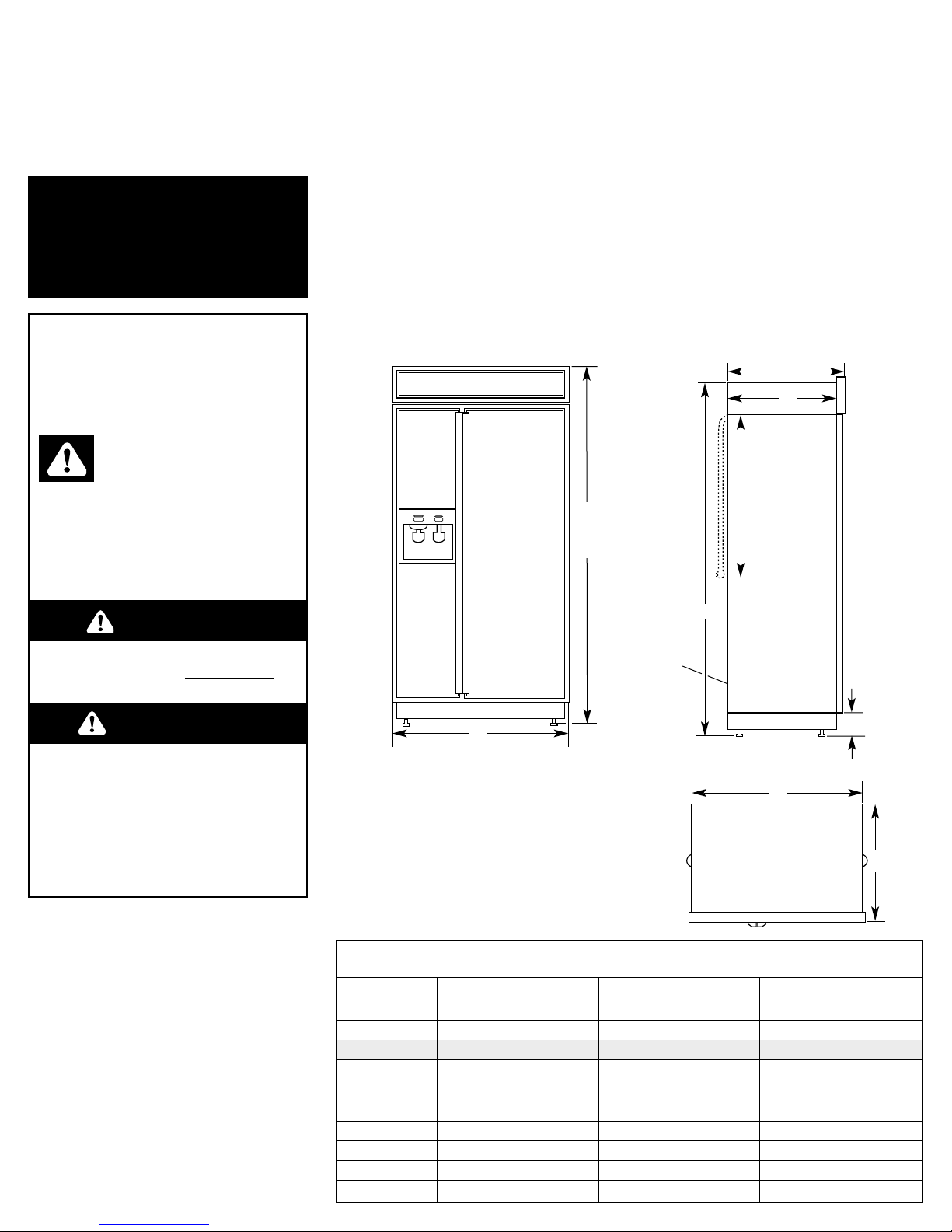
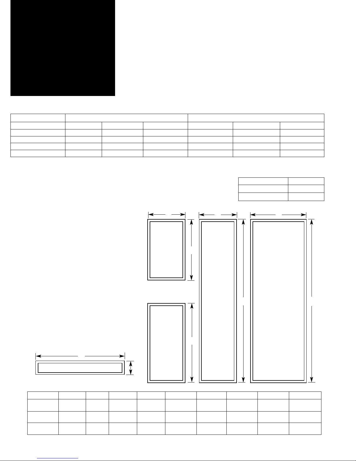
36" (91 cm) 42" (106 cm) 48" (122 cm)
A 36" (91 cm) 42" (106 cm) 48" (122 cm)
B
Panel model
83-5/8" (212 cm)* 83-5/8" (212 cm)* 83-5/8" (212 cm)*
B 83-1/8" (211 cm) 83-1/8" (211 cm) 83-1/8" (211 cm)
C 25-1/8" (64 cm) 25-1/8" (64 cm) 25-1/8" (64 cm)
D 23-1/2" (60 cm) 23-1/2" (60 cm) 23-1/2" (60 cm)
E 3-1/2" (9 cm)* 3-1/2" (9 cm)* 3-1/2" (9 cm)*
F 83-1/8" (211 cm)* 83-1/8" (211 cm)* 83-1/8" (211 cm)*
G 24" (61 cm) 24" (61 cm) 24" (61 cm)
H 35" (89 cm) 41" (104 cm) 47" (119 cm)
I 25" (63.5 cm) 25" (63.5 cm) 25" (63.5 cm)
Before you
start...
Keep cardboard shipping piece or
plywood under refrigerator until it is
installed in the operating position.
Note: If you are using a reverse osmosis
water filtering system, it is recommended
that the refrigerator’s water filter be
removed and the cap be replaced in the
grille. (See Use and Care Guide.)
Front view
A
C
D
G
E
F
Product dimensions
* Dimensions shown are for leg levelers
extended 1/8" (3 mm) below rollers. For
levelers fully extended 1-1/4" (32 mm)
below rollers, add 1-1/8" (29 mm) to this
dimension.
Important:
Observe all governing codes and
ordinances.
It is your responsibility to:
• Comply with installation specifications
and dimensions.
• Properly install refrigerator.
• Remove any moldings or decorative
panels that prevent the refrigerator
from being serviced.
• Make sure that you have these
materials necessary for proper
installation:
1/4" (6 mm) copper tubing with
shutoff valve
Panel models only:
The “B” dimension can be increased or
decreased 1/2 inch (1.3 cm) by using
Grille Kits available from your dealer.
To increase: use “84-inch” Grille Kit
No. 4378788 (Silver Trim) or 4378789
(White Trim).
To decrease: use “83-inch” Grille Kit
No. 4378786 (Silver Trim) or 4378787
(White Trim).
Top view
H
I
Side view
1/4" (6 mm) compression fitting
6 – #8 x 3" (7.6 cm) wood screws
(Longer screws may be
required.)
2 – 2" x 4" x 32" (5 cm x 10 cm x
81 cm) min. wood boards
(See Page 4.)
• Assure that floor will support
refrigerator weight (more than
600 lb/272 kg), door panels,
and contents.
• Provide a properly grounded electrical
outlet.
• Assure that location will permit
appliance doors to open 110°
minimum.
B
See
Note.
Panel models and wraparound metal door models
Dispenser and Non-Dispenser
Wraparound metal
model
Important:
• Installer: Leave Installation
Instructions with the homeowner.
• Homeowner: Keep Installation
Instructions for future reference.
• Save these Installation Instructions for
the local electrical inspector’s use.
5 ft. (1.5 m)
water line
tubing
coiled and
taped to
back
You can be killed or seriously
injured if you don’t follow
instructions.
D ANGER
Your safety and the safety of
others are very important.
We have provided many important
safety messages in this manual and
on your appliance. Always read and
obey all safety messages.
All safety messages will tell you
what the potential hazard is, tell you
how to reduce the chance of injury,
and tell you what can happen if the
instructions are not followed.
You can be killed or seriously
injured if you don’t immediately
follow instructions.
WARNING
This is the safety alert
symbol.
This symbol alerts you to
potential hazards that can kill or hurt
you and others.
All safety messages will follow the
safety alert symbol and either the
word “DANGER” or “WARNING”.
These words mean:
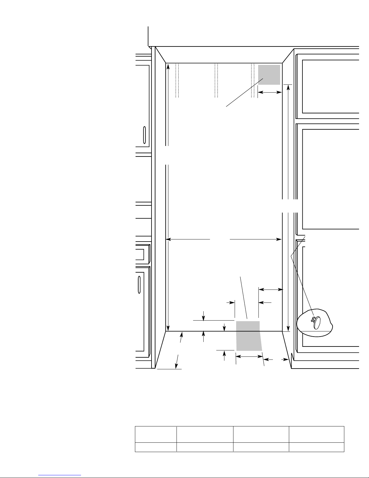
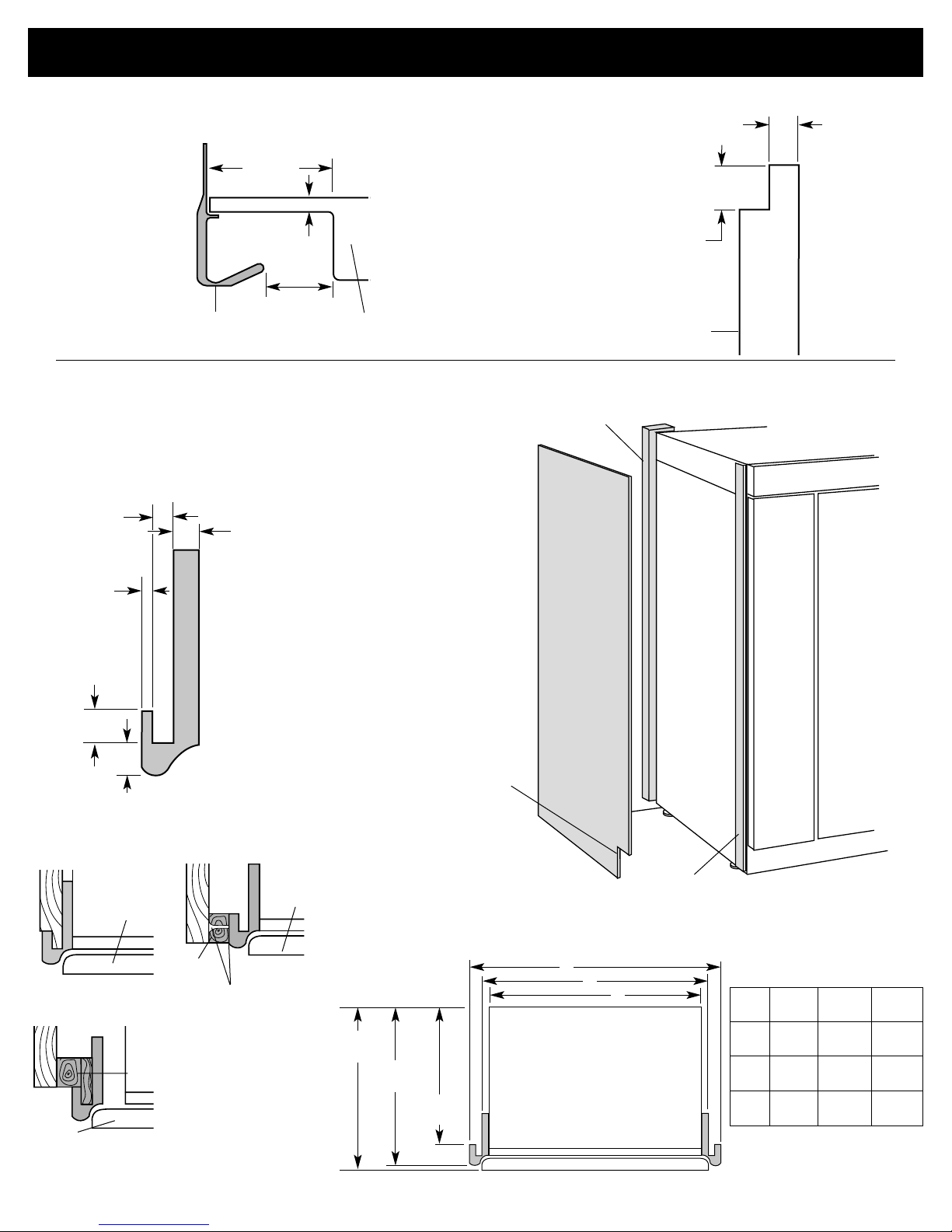
Model
Width min.
36" (91 cm)
35-1/2" (90 cm)
42" (106 cm)
41-1/2" (105 cm)
48" (122 cm)
47-1/2" (120 cm)
Built-in opening
requirements &
dimensions
All dimensions ±1/8" (3 mm)
Grounded electrical
outlet location
Grounded electrical
outlet is required.
Mark stud
locations on
rear wall
80" - 90"
(203-229 cm)
above floor.
Floor: Must support refrigerator,
contents, and door panels.
*If a recommended water line location is used, no
additional plumbing needs to be purchased.
Water line must
provide 15-100 psi
(103-690 kPa) water
pressure. Rough in
water line before
installing
refrigerator.
7"
(18 cm)
6"
(15.2 cm)
6" (15.2 cm)
3" (7.6 cm)
If optional side panel is used,
install support board on rear
wall if opening depth is
25" (63.5 cm) or more.
83-1/4” (211.5 cm) min.
84-3/4” (215 cm) max.
to bottom of solid soffit.*
23-1/2”
(60 cm) min.
Opening dimensions
Page 3
Water line
location can be
through floor
or wall.
*
11"
(28 cm)
1/2" (12 mm) hole for plumbing
can be located anywhere within
shaded area.
The built-in refrigerator can be
installed:
• recessed in the cabinet opening.
• at the end of cabinets using a side
panel to enclose the refrigerator side.
Select one method and use dimensions
given. Dimensions shown provide 0"
(0 cm) clearance.
77"
(196 cm)
6"
(15.2 cm)
6"
(15.2 cm)
Width
* If solid soffit is not available, see
“Anti-tip requirements” on Page 4.
One of the three methods shown
must be used.
The water hookup
connection may be
located in the base
cabinet on either side
of the refrigerator. The
right hand side is
recommended.*
Note: The access hole
through the cabinet
must be within 1/2”
(12.7 mm) of rear wall.
Top front
of refrigerator
Freezer
door
Refrigerator
door
C
D
B
A
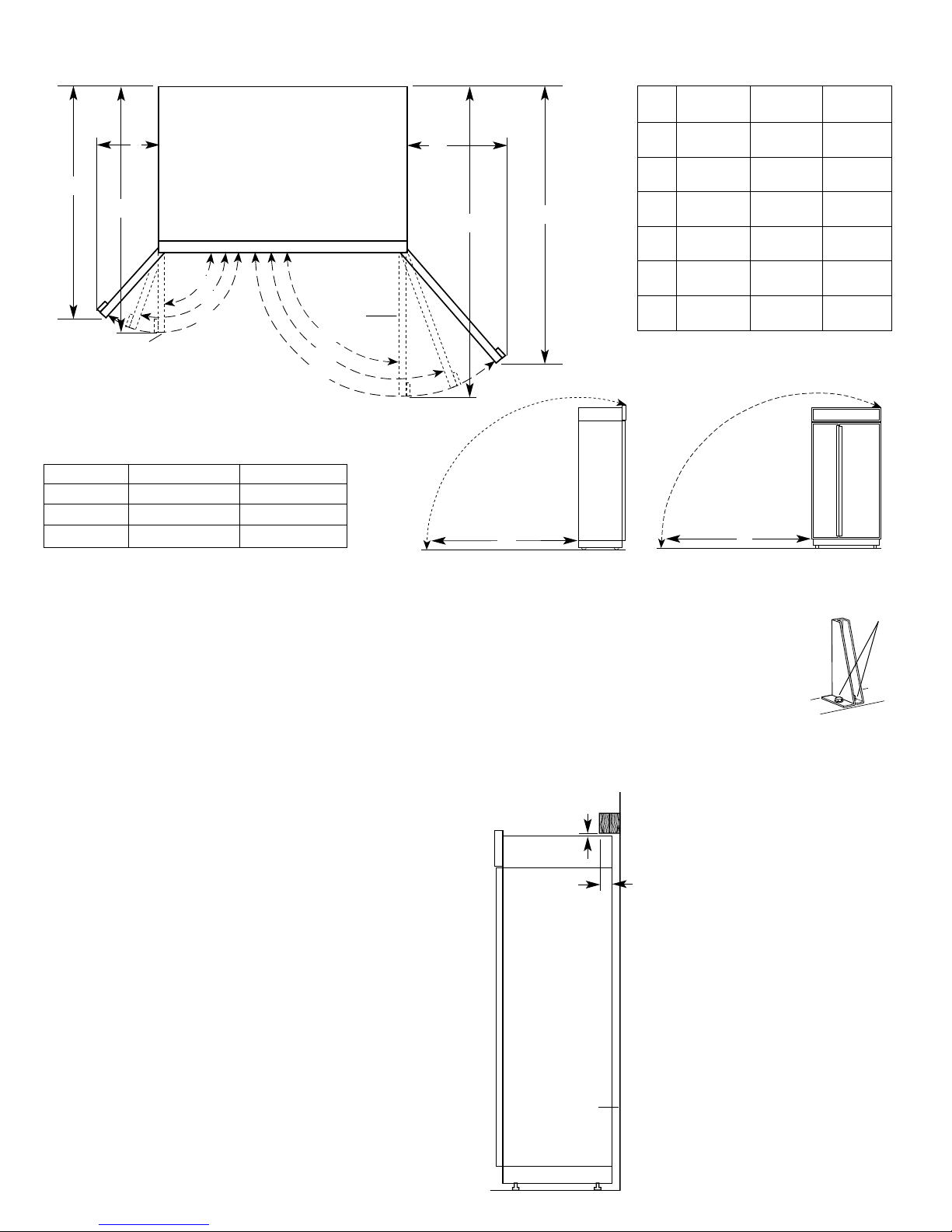
Door swing dimensions
If a solid soffit 1” (2.5 cm) max. above refrigerator is not
available, prevent the refrigerator from tipping during
use, as shown.
Securely attach a 32” (81 cm) long min. wood board(s) to
wall studs behind refrigerator. The wood screws must be
screwed into the studs 1-1/2” (3.8 cm) min. The board(s)
must overlap the compressor cover as shown.
If additional ceiling clearance is required for tipping the
refrigerator, follow the directions for your model.
For wraparound metal models:
• Grasp both ends of the louver panel. Push straight up,
then pull out and remove.
• Remove the two screws attaching grille panel, slide the
grille panel down and remove.
• Remove the six screws attaching each cabinet side trim to
the refrigerator and remove the side trims.
• Reassemble after dolly has been removed from refrigerator.
For panel models:
• Grasp both ends of the panel. Push straight
up, then pull out and remove.
• Remove the four screws attaching the frame
to the brackets and remove.
• Remove two screws attaching each bracket
to the refrigerator and remove
• Reassemble after dolly has been removed from refrigerator.
Board(s) must be long enough to fully
cover width of compressor cover.
It is recommended that board(s) be
installed before refrigerator is installed.
Locate the board(s) so the bottom surface
of the board(s) are 84” (213 cm) from the
floor. During installation, raise the
refrigerator up so there is 1/4” (6.4 mm)
max. between top of the refrigerator and
bottom of anti-tip board(s).
DO NOT crush the condenser cover when
raising the rear leveling legs.
1/4" (6.4 mm)
max.
2" (5.1 cm)
min.
rear
wall
Page 4
Anti-tip requirements
Tipping radius
Forward/backward
tipping radius
Side
tipping radius
Size A B
36" (91 cm) 87-1/4" (222 cm) 90-1/2" (230 cm)
42" (106 cm) 87-1/4" (222 cm) 93" (236 cm)
48" (122 cm) 87-1/4" (222 cm) 96" (244 cm)
A
B
A
B
C
D
E
F
36"
91 cm
38-1/2"
(98 cm)
36-1/16"
(92 cm)
43-1/2"
(110 cm)
40"
(102 cm)
19-3/4"
(50 cm)
14-1/2"
(37 cm)
42"
106 cm
41"
(104 cm)
38"
(97 cm)
47"
(119 cm)
42-9/16"
(108 cm)
23-1/4"
(59 cm)
17-1/4"
(44 cm)
48"
122 cm
43-1/2"
(110 cm)
40"
(102 cm)
50-1/2"
(128 cm)
45-1/4"
(115 cm)
26-3/4"
(68 cm)
19-3/4"
(50 cm)
Location must permit doors to open to 110°
min. Allow 4-1/2 inch (11.4 cm) min. space
between refrigerator side and corner wall.
130°
130°
90°
90°
E
F
Note: Dolly wheel height must be added to tipping
radius when a dolly is used.
110°
110°
bracket
screws
Color Kit number
Matte Aluminum 4387989
White 4387990
Parts that
must be
ordered
separately or
custom made
1. Panel kits
Four kits, containing colored acrylic
or stainless steel door and top grille
panels, are available through your
KitchenAid dealer or by calling
KitchenAid Parts and Accessories at
1-800-442-9991. Follow the kit
instructions for installing the panels.
Panel kit numbers
Size
White
Black
Biscuit
Stainless Steel
36" (91 cm)
4318635
4318632
4392879
4318641
36" (91 cm)
4378650
4378653
4392886
4378659
42" (106 cm)
4318636
4318633
4392880
4318642
42" (106 cm)
4378651
4378654
4392887
4378660
48" (122 cm)
4318637
4318634
4392881
4318643
48" (122 cm)
4378652
4378655
4392888
4378661
2. Extended door handle kits
Two kits, containing one freezer door handle and one refrigerator door handle, are
available through your KitchenAid dealer or by calling KitchenAid Parts and
Accessories at 1-800-442-9991. Use extended door handles when additional finger
clearance is needed between the door handle and custom panel. Follow the kit
instructions for installing the door handles.
3. Custom panels
The custom panel weight must NOT
exceed amounts listed.
Panels weighing more than amounts
listed may cause product damage.
C F H
D
G
I
E
Freezer door panels
(with dispenser)
Maximum
combined
weight of
both panels:
30 pounds
(13.5 kg)
Maximum
combined
weight of
both panels:
30 pounds
(13.5 kg)
Freezer door
panel
(non
dispenser)
Maximum
weight:
30 pounds
(13.5 kg)
Refrigerator door
panel
Maximum
weight:
50 pounds
(23 kg)
Page 5
Model Non-dispenser Dispenser
A
B*
Size
36"
(91 cm)
42"
(106 cm)
48"
(122 cm)
A
32-3/8"
(82 cm)
38-3/8"
(97 cm)
44-3/8"
(113 cm)
B
*
6"
(15 cm)
6"
(15 cm)
6"
(15 cm)
C
14-1/4"
(36 cm)
16-3/4"
(43 cm)
19-1/4"
(49 cm)
D
23-7/16"
(60 cm)
23-7/16"
(60 cm)
23-7/16"
(60 cm)
E
34-7/16"
(87 cm)
34-7/16"
(87 cm)
34-7/16"
(87 cm)
F
14-1/4"
(36 cm)
16-3/4"
(43 cm)
19-1/4"
(49 cm)
G
70-7/16"
(179 cm)
70-7/16"
(179 cm)
70-7/16"
(179 cm)
H
19-1/4"
(49 cm)
22-3/4"
(58 cm)
26-1/4"
(67 cm)
I
70-7/16"
(179 cm)
70-7/16"
(179 cm)
70-7/16"
(179 cm)
Top grille panel [max. wt.: 10 lb./(4.5 kg)]
NOTE: Dimensions shown have a
±1/16 (1.5 mm) tolerance. Panels
that are more than 1/4" (6 mm) thick
must be routed. If using routed
panels, add 1/16" (1.5 mm) to
dimensions shown.
If panels are less than 1/4" (6 mm)
thick, install a filler panel between
doors and decorative panels.
*Dimension “B” can increase or decrease 1/2" (1.3 cm) if grille kits listed on page 2 are used.
Panel kits are not required for “factoryinstalled stainless steel panel” models
or wraparound metal door models.
Dimensions for
routing panel
edges
Side view
3/4"
(19 mm)
min.
1/4"
(6 mm) max.
panel
End view of handle side of panel
panel
handle
2" (5 cm)
min.
1/4" (6mm )max.
Custom panels
more than 1/4"
(6 mm) thick:
Route entire length
or selected areas of
handle side of
panels 3-1/4"
(8.25 cm).
Thickness:
1/2" (12 mm)
minimum to
prevent warping.
Width and height:
depend on
installation type.
Notches for toe
panel recess
(if desired).
Determine
installation height
before cutting
notches.
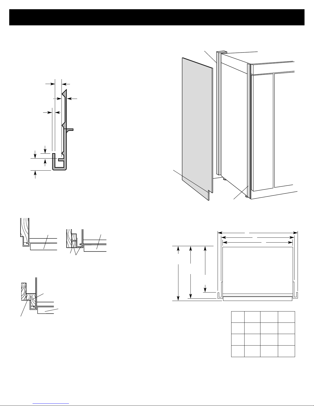
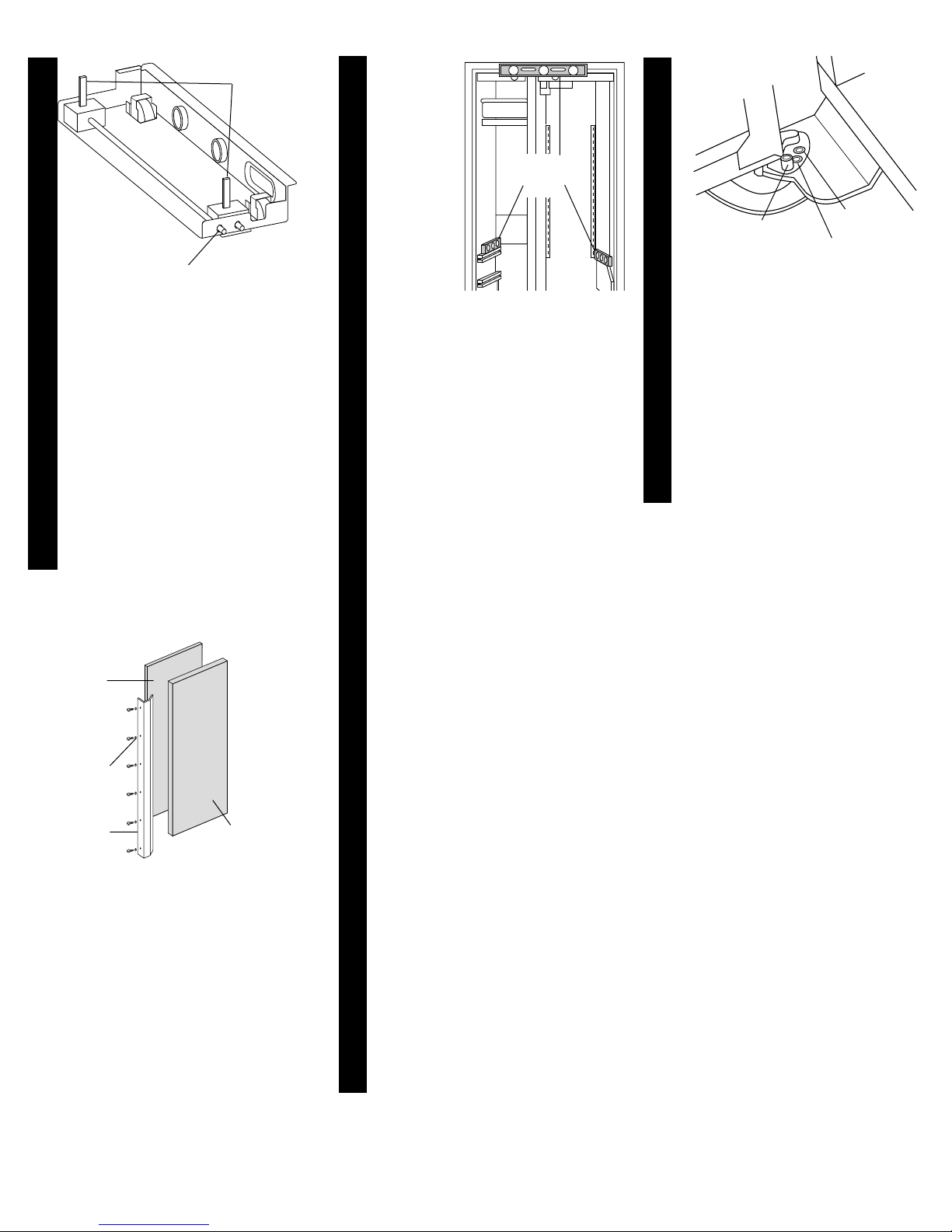
If side panel will be installed inside
side trim and the side panel is more
than 1/4" (6 mm) thick, route front
edge of panel to fit trim piece.
side panel
support nailer
side trim piece
Page 6
End view of side trim piece
5/32"
(4 mm)
1/4"
(6 mm)
1/16"
(1.5 mm)
7/32"
(5.5 mm)
13/32" (10 mm)
side panel inside
side trim piece
3. Side panels
recessed side panel
outside side trim piece
3-1/4"
(8.25 cm)
min.
A
B
C
Model
A
B
C
36"
(91 cm)
36"
(91 cm)
35-1/2"
(90 cm)
35"
(89 cm)
42"
(106 cm)
42"
(106 cm)
41-1/2"
(105 cm)
41"
(104 cm)
48"
(122 cm)
48"
(122 cm)
47-1/2"
(120 cm)
47"
(119 cm)
25"
(63.5 cm)
24-1/8"
(61.3 cm)
23-1/2"
(59.7 cm)
Panel models
Attach support
board with screw
or adhesive
compatible with
aluminum and
wood.
support
board
door
side panel outside
side trim piece
door
door
support
board
Rout front edge of support board or attach
1/4" board for retention in cabinet side trim.
Page 7
Wraparound metal door models
Thickness:
1/2" (12 mm)
minimum to
prevent warping.
Width and height:
depend on
installation type.
Notches for toe
panel recess
(if desired).
Determine
installation height
before cutting
notches.
If side panel will be installed inside
side trim and the side panel is more
than 1/4" (6 mm) thick, route front
edge of panel to fit trim piece.
side panel
support nailer
side trim piece
End view of side trim piece
5/32"
(4 mm)
1/4"
(6 mm)
1/16"
(1.6 mm)
3/16"
(4.8 mm)
13/32" (10.5 mm)
side panel inside
side trim piece
side panel outside
side trim piece
door
door
3. Side panels
door
recessed side panel
outside side trim piece
A
B
C
Model
A
B
C
36"
(91 cm)
36"
(91 cm)
35-1/2"
(90 cm)
35"
(89 cm)
42"
(106 cm)
42"
(106 cm)
41-1/2"
(105 cm)
41"
(104 cm)
48"
(122 cm)
48"
(122 cm)
47-1/2"
(120 cm)
47"
(119 cm)
25"
(63.5 cm)
23-3/8"
(59.4 cm)
22-13/16"
(57.9 cm)
Rout front edge of support board or attach
1/4" board for retention in cabinet side trim.
Attach support board with screw
or adhesive compatible with
aluminum and wood.
support
board
support
board
Electrical &
water supply
requirements
A 120-volt, 60-Hz, AC-only, 15- or
20-ampere, fused, electrical supply is
required. A time-delay fuse or circuit
breaker is recommended. It is
recommended that a separate circuit
serving only this appliance be
provided.
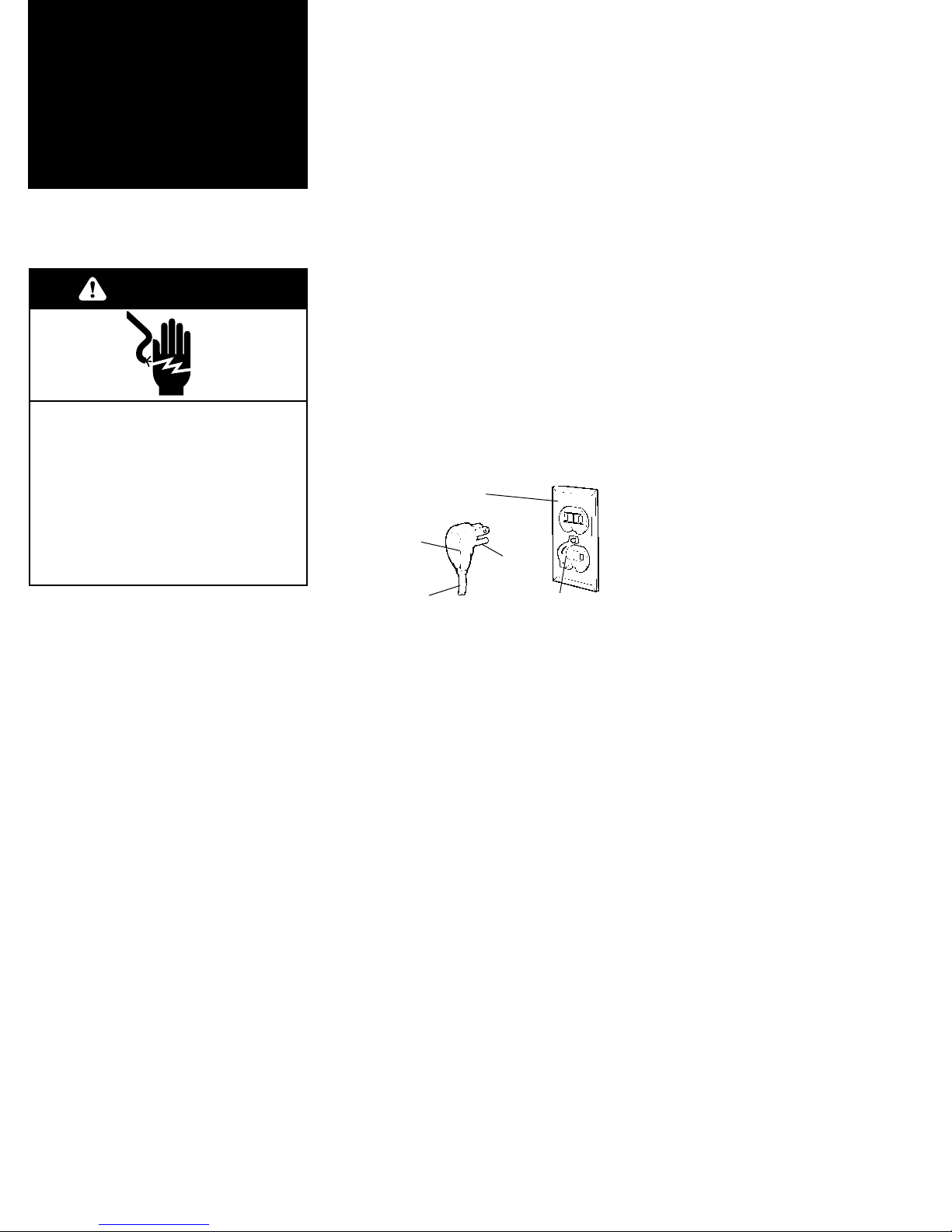
This appliance is equipped with a
power supply cord having a 3-prong
ground plug. To minimize possible
shock hazard, the cord must be
plugged into a mating 3-prong,
ground-type outlet, grounded in
accordance with the National
Electrical Code, ANSI/NFPA 70 —
latest edition* or Canadian Electrical
Code, C22.1-1982 and C22.2 No.
01982 (or latest edition)**, and all
local codes and ordinances.
Copies of the standard listed may
be obtained from:
* National Fire Protection Association
One Batterymarch Park
Quincy, Massachusetts 02269
** CSA International
8501 East Pleasant Valley Road
Cleveland, Ohio 44131-5575
Electrical requirements
ground
prong
power supply
cord
retainer
Water supply requirements
Water line to refrigerator must
provide 15-100 psi (103-690 kPa)
water pressure.
Provide water line hookup located as
shown on Page 3.
Page 8
3-prong ground-type
outlet
3-prong
ground plug
If codes permit and a separate
ground wire is used, it is
recommended that a qualified
electrician determine that the
ground path is adequate.
Do not ground to gas pipe.
Check with a qualified electrician if
you are not sure the appliance is
properly grounded.
Do not have a fuse in the neutral or
ground circuit.
It is the customer’s responsibility:
To contact a qualified electrical
installer.
To assure that the electrical
installation is adequate and in
conformance with the National
Electrical Code, ANSI/NFPA 70 —
latest edition* or Canadian Electrical
Code, C22.1-1982 and C22.2 No.
01982 (or latest edition)**, and all
local codes and ordinances.
WARNING
Electrical Shock Hazard
Plug into a grounded 3-prong
outlet.
Do not remove ground prong.
Do not use an adapter.
Do not use an extension cord.
Failure to follow these
instructions can result in death,
fire, or electrical shock.
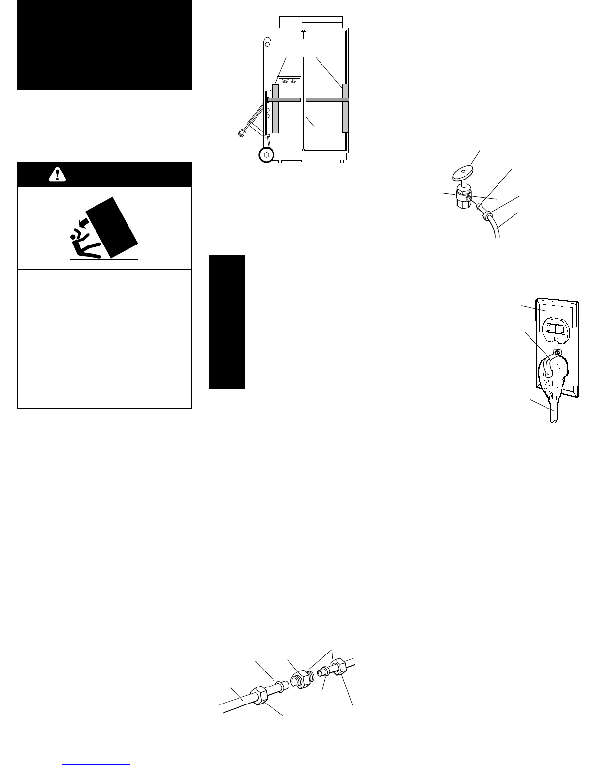
must be brass
or nickel plated
brass with
7/16-24 thread.
1.Remove and save literature
package and parts bag taped to
refrigerator door. Remove four brackets
(two on each side) that attach shipping
base to refrigerator bottom.
Do not remove tape and door bracing
until refrigerator is in final position.
Installation
steps
Do Not lower the refrigerator
against the shipping base when
removing the shipping base.
Do Not remove protective film until
refrigerator is in operating position.
All four leveling legs must contact
the floor to support and stabilize the
full weight of the refrigerator.
Keep cardboard shipping piece or
plywood under refrigerator until it is
installed in operating position.
Parts supplied for installation:
• base grille
• miscellaneous parts bag
Check that all parts were included.
4.Place pieces of shipping carton
on the floor when rolling dolly and
refrigerator into the house. Move
refrigerator close to built-in opening.
corner
post over
handle
Page 9
7.Set power
switch at top of
cabinet to “OFF”
position.
Plug power supply cord into
grounded outlet. Install
retainer on grounded
outlet using screw
from parts bag.
8.Place top of cardboard
carton or plywood under refrigerator.
Remove dolly. Open appliance doors
and remove all boxes, parts packages
and packing materials from refrigerator
and freezer compartments. Do Not
remove protective film.
To prevent floor damage make sure
levelers are raised (not touching the
floor) and refrigerator is on rollers
before moving.
Move the refrigerator straight back and
evenly into the opening. Check that:
• water hookup tubing is not kinked.
• power supply cord is on top of
refrigerator next to cover.
retainer
grounded
outlet
power
supply
cord
2.Place appliance dolly under the
freezer side of refrigerator. Pass the dolly
strap under the handles then loosely
wrap dolly strap around refrigerator.
Insert carton corner posts between strap
and side trim. Carefully tighten strap,
making sure side trim is protected.
corner posts
over side trim
Tip Over Hazard
Refrigerator is top heavy and tips
easily when not completely
installed.
Keep doors taped closed until
refrigerator is completely
installed.
Use two or more people to move
and install refrigerator.
Failure to do so can result in
death or serious injury.
WARNING
C
R
I
T
I
C
A
L
3.If 32” (81 cm) long min.
wood board(s) will be used
to prevent refrigerator from
tipping during use, install
now.
S
T
E
P
5.Before attaching refrigerator water
line to water supply, flush at least 2
quarts (1.9 L) of water through the
water supply and into a bucket to get rid
of any particles in the water supply line.
Turn water valve off.
Check for leaks in water supply.
Style 1
bulb
nut (provided)
ferrule
(purchased)
coupling
(purchased)
nut
(purchased)
tubing from
refrigerator
Push the tubing into the coupling as far
as it will go. Slide the nut and ferrule
forward and finger tighten the nut. Turn
nut two (2) more turns with wrench.
Insert the bulb end of tubing into
purchased coupling, slide nut down
and finger tighten. Turn nut two (2)
more turns with wrench.
Style 2
nut
(provided)
tubing from
refrigerator
bulb
valve must be brass or nickel
plated brass with 7/16-24 thread.
Push the bulb end of the tubing into the
water valve as far as it will go. Slide the
nut forward and finger tighten. Tighten
nut two (2) more turns with wrench.
6.Make connection to refrigerator.
Untape tubing from back of refrigerator.
Use Style 1 or Style 2, depending on
your installation.
Slide the purchased nut then the
purchased ferrule onto the tubing.
decorative
panel
Filler panel
required if
panels are less
than 1/4"
(6 mm) thick.
If panels are
more than
1/4" (6 mm)
thick, route
panel edges
on all sides.
door
handle
nylon
washers
Page 10
10. Wraparound metal door
models: go to step 12.
Panel models: Remove all tape and
door bracing from refrigerator and
freezer doors. Remove screws attaching
handles to door frames. Slide decorative
door panels into door frames.
If panels are less than 1/4" (6 mm)
thick, install a filler panel between door
and decorative panel.
If panels are more than 1/4" (6 mm)
thick, route panel edges on all sides.
13. Replace door handles.
Check that the top of both door
handles are aligned.
If door handles are not
aligned, loosen all handle screws
and adjust door handles up or
down. Tighten screws.
If any of the white door screws
are damaged, replace them with
additional screws provided in the
parts package.
C
R
I
T
I
C
A
L
S
T
E
P
S
door stop set screw
(130° position)
90° position
bottom hinge
14. Check that
doors can open freely. If doors
open too wide, remove door
stop screw from bottom door
hinge. Hold door open to a
position that is less than 90°.
Replace door stop screw in the
110° door stop position in
bottom hinge and tighten
screw. If door does not clear
countertop after door has been
adjusted, countertops may need
to be mitered.
C
R
I
T
I
C
A
L
S
T
E
P
11.
Open
doors. Place
a level
against
underside
of door
trim, on
refrigerator
crisper
guide and
on freezer
basket
guide as shown. Adjust leveling
legs until refrigerator is level.
Check that all four leveling legs
contact floor and support the full
weight of the refrigerator. Door
panels must be installed before
leveling.
Check that
refrigerator is
level.
C
R
I
T
I
C
A
L
S
T
E
P
leveling
legs
Use 5/16" (8 mm)
socket and ratchet.
9.Use socket wrench to turn leg
levelers on both sides of
refrigerator to the right (clockwise)
until refrigerator weight is
supported by leveling legs. The
rollers should be off the floor.
To avoid cabinet damage, do not
apply more than 50 in/lb (58 cm/kg)
of torque to the leveling legs.
Note: All four leveling legs must
contact the floor to support and
stabilize the full weight of
refrigerator. Rollers are for
moving refrigerator and not for
permanent support.
rear
front
12. Check that both
refrigerator and freezer doors are
aligned and level.
If doors need to be adjusted left
or right or in or out, loosen the
3/8" hex head screws in top
hinges.
If doors need to be adjusted up
or down, remove door stop screw
from bottom door hinge. Remove
locking plate. Use 1/2" open-end
wrench or channel-lock pliers to
turn bushing to the left
(counterclockwise) to move door
up, to the right (clockwise) to
move door down. Check that
doors are level. Replace locking
plate and door stop screw.
You may need to turn bushing
slightly to align locking plate so
that door stop screw can be
inserted.
110° position
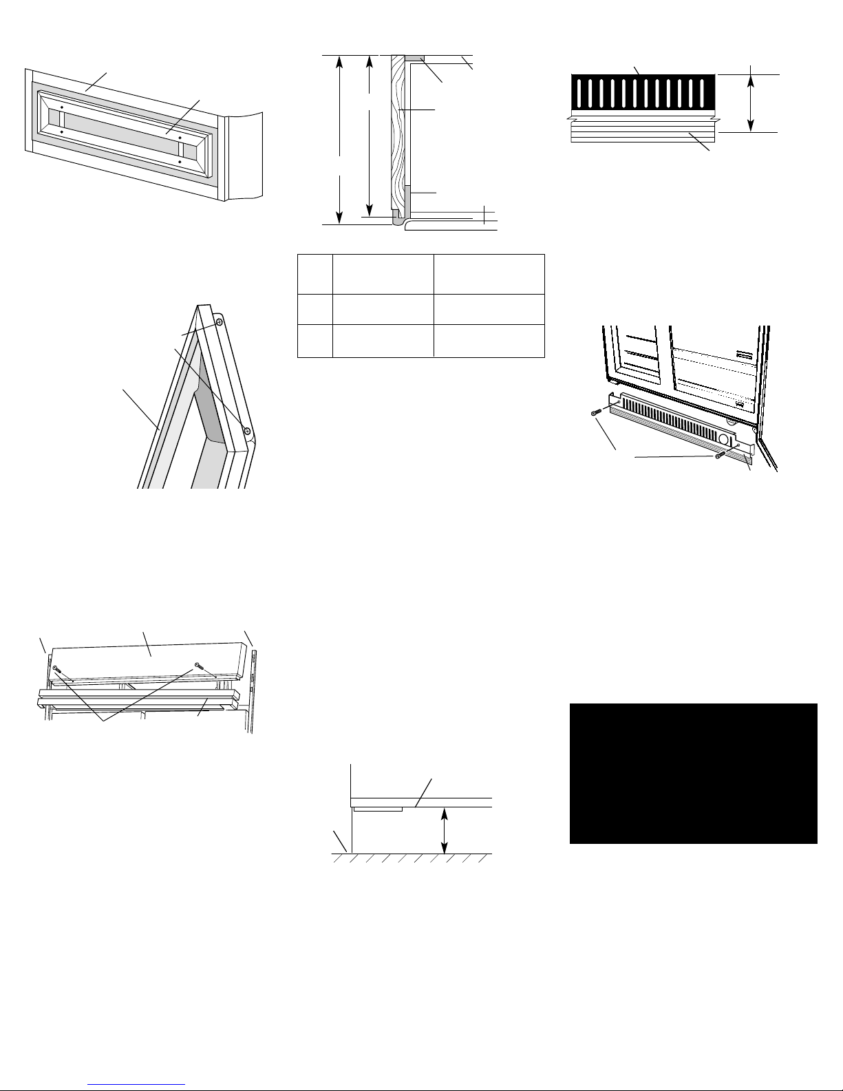
22. Measure this same distance
from the top of the bottom grille to
the closest "V" groove on the grille
skirt.
Use a knife to score down the "V"
groove and break skirt at the score
line.
23. Attach the bottom grille and
skirt assembly to the cabinet with the
2 screws.
To get the most efficient use
from your new built-in
refrigerator, read your
KitchenAid Use and Care Guide.
Keep Installation Instructions
and Guide close to built-in
refrigerator for easy reference.
24. Set refrigerator and freezer
compartment controls to the midpoint
between “COLD” and “COLDEST.”
Check that the compressor is operating
properly and that all five lights are
working.
19. Open refrigerator doors and
remove protective film from door
frame. Recheck water connections at
bottom of refrigerator for leaks.
Install shelves and bins in refrigerator
and freezer compartments.
Note: If construction will continue after
refrigerator is installed, rotate control in
freezer compartment counterclockwise
to the “OFF” position.
screws
grille and
skirt assembly
remove 2
screws
top grille decorative
panel
grille panel
cabinet
side trim
cabinet
side trim
louver
assembly
grille panel
screws
16. Panel models: Remove screws
and side trim from one side of the
decorative panel. Insert your panel.
Reattach side trim and screws.
17. Panel models: Slide
decorative panel down to reattach to
top grille.
18. If side panels are not used,
go to Step 19.
If built-in area depth is 25"
(63.5 cm) or more, side panels can be
installed inside the side trim or attached
to the outside of the side trim.
• Inside side trim piece: Slide front
edge of routed side panel into trim
piece. Nail rear edge of panel to
support board.
NOTE: KitchenAid is not responsible
for the removal or addition of
molding or decorative panels that
would prevent the refrigerator from
being serviced.
A
B
Panel Wraparound
models (shown) metal
door models
24" 23"
(61 cm) (58.4 cm)
24-5/8" 23-3/8"
(62.5 cm max.) (59.4 cm)
side panel
side trim
support board
rear wall
door
Top view
B
A
15. Wraparound metal door
models: go to step 17.
Panel models: Slide decorative panel
assembly up to remove from top grille
assembly.
top grille
assembly
decorative panel
assembly
20. Remove the grille and skirt
package taped to front of refrigerator.
Remove grille and skirt and 2 screws
from package.
21. Open refrigerator door and
measure the distance from the bottom
of refrigerator cabinet to the floor.
refrigerator cabinet
bottom
measure this
distance
floor
grille and skirt assembly
score "V" groove
measured distance
(from step 21)
Page 11
 Loading...