

KitchenAid KIRD807HSS0 Installation Instructions And Use And Care Manual

IMPORTANT:
Read and save
mMPORTANT:
Installer: Leave Installation Unstrucfions with
the homeowner.
Homeowner: Keep UnstaHafion Unstrucfions for
future reference.
Save Installation Instructions for UocaUeUectdcd
inspector's use.
Part No. 4329225/8284826 Rev.A
Quick Reference
TabNeof Contents:
Pages
[] Before you start
[] EUectdcaUrequirements
[] Product dimensions
[] Cabinet dimensions
[] Countertop cutout dimensions
] Vent system requirements
Untedor-mounted vent motor
[_-[] UnstaHation steps
] Vent system requirements
Exterior-mounted vent motor
[_-[_ Installation steps
[] Use and Care Information
[] Accessories
Your safety and the safety of
others are very important,
We have provided many important
safety messages in this manual
and on your appliance. Always
read and obey all safety
messages.
This is the safety alert
symbol.
This symbol alerts you to
potential hazards that can kill or
hurt you and others.
All safety messages will follow the
safety alert symbol and either the
word "DANGER" or "WARNING".
These words mean:
You can be killed or seriously
injured if you don't immediately
foltow instructions.
You can be killed or seriously
injured if you don't foltow
instructions.
All safety messages will tell you
what the potential hazard is,tell you
how to reduce the chance of injury,
and tell you what can happen if the
instructionsare not followed.
mmportant: Observe aH governing
codes and ordinances,
Proper installation is your
responsibility. Make sure you have
everything necessary for correct
installation. It is the responsibility
of the installer to comply with the
installation clearances specified on
the model/serial rating plate.The
model/serial rating plate is located
on the front of the downdraft vent
above the wiring box cover.
Mobile home installation
The installation of this range hood
must conform to the Manufactured
Home Construction Safety
Standards, Title 24 CFR, Part 328
(formerly the Federal Standard for
Mobile Home Construction and
Safety, Title 24, HUD, Part 289) or
when such standard is not
applicable, the Standard for
Manufactured Home Installation
1982 (Manufactured Home Sites,
Communities and Setups) ANSI
A225.1/NFPA 591A*, or latest
edition, or with local codes.
Check location where downdraft
vent will be installed.The location
should be away from strong draft
areas, such as windows, doors
and strong heating vents or fans.
Before making countertop cutout,
check that downdraft vent and
cooktop location will clear cabinet
walls, backsplash, and rear wall
studs inside cabinet.
ALL OPENINGS IN THE WALL OR
FLOOR WHERE RETRACTABLE
DOWNDRAFT VENT iS TO BE
INSTALLED MUST BE SEALED.
Electrical ground is required. See
"Electrical requirements;' page 3.
When installing downdraft vent,
the cabinet drawer will need to be
removed and the drawer front
installed permanently to cabinet.
Note: Downdraft vent is installed
directly behind the cooktop. Install
downdraft vent first.
Cabinet construction: Downdraft
vent is designed for use in a
cabinet with a depth of 24"
(61 cm). Some installations
require a countertop deeper than
25" (63.5 cmL See chart on page 5.
The maximum depth of the
overhead cabinet is 13" (33 cm).
Overhead cabinets installed at
either side of the downdraft vent
must be 18" (45.7 cm) above the
cooking surface.
See cooktop Installation
instructions before making any
cutouts and for the minimum
distance between the front edge
of the countertop and front edge
of cooktop.The minimum
horizontal distance between the
overhead cabinets is the same as
the width of the installed
downdraft vent.
When installing a 36" (91.4 cm)
retractable downdraft vent with
"Create-A-Cooktop" modules, the
optional support must be installed
on the front of the downdraft vent.
See installation steps for details.
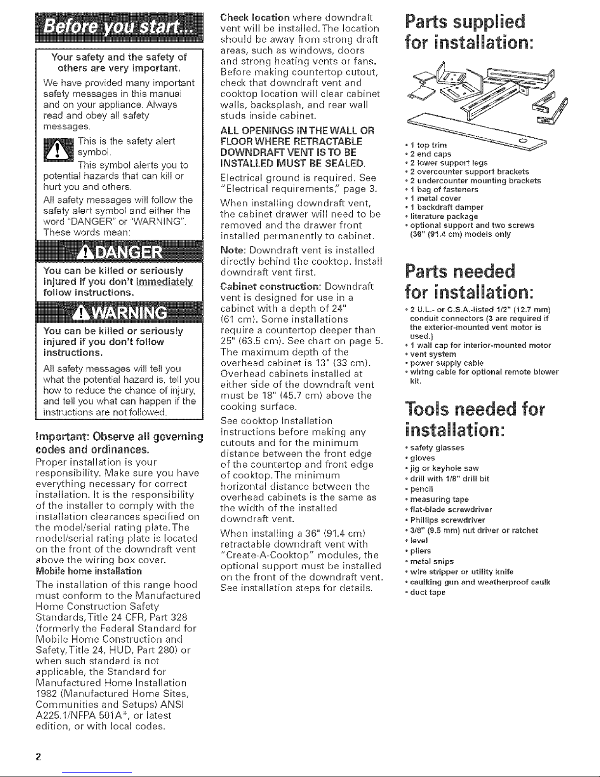
Parts supplied
for installation:
• t top trim
2 end cape
• 2 lower support legs
2 overcounter support brackets
2 undemounter mounting brackets
• 1 bag of fasteners
t meta_ cover
• 1 backdraft damper
• literature package
• optional support and two screws
(36" (91.4 era) models only
Parts needed
for installation:
• 2 U.L.= or C.S.A.4isted 1/2" (12.7 ram)
conduit connectors (3 are required if
the exterior-mounted vent motor is
used.}
• 1 wall cap for interior-mounted motor
• vent system
• power supply cable
• wiring cable for optiona_ remote b_ower
kit.
Tools needed for
installation:
• safety glasses
• g_oves
• jig or keyhole saw
• drill with 118" drill bit
• pencil
• measuring tape
• flat=b_ade screwdriver
• Phillips screwdriver
• 318" (9.5 ram} nut driver or ratchet
• leve_
• pliers
• metal snips
• wire stripper or utility knife
caulking gun and weatherproof caumk
• duct tape
important: Observe aim governing
codes and ordinances.
it is the customer's responsibimity:
• To contact a quamified emectricam
installer.
• To assure that the electrical
installation is adequate and in
conformance with National
Electrical Code, ANSi/NFPA 70
= latest edition% or CSA
Standards C22.1-94, Canadian
Electrical Code, Part 1 and
C22.2 No. 0-M91 - latest
edition** and all local codes
and ordinances.
if codes permit and a separate
ground wire is used, it is
recommended that a qualified
electrician determine that the
ground path i$ adequate.
Do not ground to a gas pipe.
Check with a qualified electrician
if you are not sure downdraft vent
is properly grounded.
Do not have a fuse in the neutral
or ground circuit.
iMPORTANT
Save installation instructions for
electrical inspector's use.
A 120-volt, 60-Hz, AC-only
electrical supply is required on a
separate 15-ampere circuit, fused
on both sides of the line. A time-
delay fuse or circuit breaker is
recommended.The fuse must be
sized per local codes in
accordance with the electrical
rating of the downdraft vent as
specified on the model/serial
rating plate located on the front
of the downdraft vent above the
wiring box cover.
THE DOWNDRAFT VENT
MUST BE CONNECTEDWITH
COPPER WIRE ONLY.
Wire sizes and connections
must conform to the
requirements of the National
Electrical Code, ANSI/NFPA 70 --
latest edition% or CSA Standards
C22.1@4, Canadian Electrical
Code, Part 1 and C22.2 No. 0-M91
latest edition __ and all local
codes and ordinances.
WARNING -- TO REDUCE THE
RISK OF FIRE, ELECTRIC
SHOCK, OR INJURY TO
PERSONS, OBSERVE THE
FOLLOWING:
Installation work and electrical
wiring must be done by qualified
person(s) in accordance with all
applicabb Codes and Standards,
including fire related construction.
Sufficient air is needed for proper
combustion and exhausting of
gases through the flue (chimney)
of fuel burning equipment to
prevent back drafting. Follow the
heating equipment
manufacturer's guideline and
safety standards such as those
published by the National Fire
Protection Association
(NFPA),and the American Society
of Heating Refrigeration and Air
Conditioning Engineers
(ASHRAE), and the local code
authorities.
When cutting or drilling into wall
or ceiling, do not damage
electrical wiring and other hidden
utilities.
Ducted fans must always be
vented to the outdoors.
WARNING --To reduce the risk
of fire, use only metal ductwork.
This unit must be grounded.
This downdraft vent should
be connected directly to the fused
disconnect (or circuit breaker)
through flexible, armored or non-
metallic sheathed, copper cable.
Allow some slack in the cable so
the downdraft vent can be moved
if servicing is ever necessary.
E,, A U.L.- or C.S.A.qisted, 1/2"
(12.7 ram) conduit connector
must be provided at each end of
the power supply cable (at the
downdraft vent and at the
junction box).
A wiring diagram is located
on the downdraft vent base
above the wiring box cover.
* National Fire Protection Association
Batterymarch Park
Quincy', Massachusetts 02269
** Canadian Standard Association
178 Rexdale Boulevard
Etobicoke (toronto), Ontario MgW 1R3
8=1/4"(21cm)
retractable
vent height
-4
!9,5 mm)
3=1/4"x 10"
18,3 cmx 26.4 cm)
I
16"
140,6 cm)
15" BLOWER
(4&6 cm} MOTOR
9=3/8"
123,8 cm)
5/_
{15.9 ram}
9" (22.9 cm)
Diameter
\ (20,8"cm)
4&6 cm
EXTERIOR=MOUNTED
BLOWER MOTOR
17=3/16"
(433 cm}
all cutouts are for
3=1/4" x 10"
(8.3 cmx 25.4 cm)
vent system
Locate power supply
junction box at lower
right hand rear corner of
cabinet,
(10.5 cm)
See cooktop manufacturer's
instructions for cooktop cutout
depth aed width_
Use dimensions for veet system
cutout location that applies to
your installation_
Vent system cutout dimensions for internal
blower models only.
Exterior mounted blower systems connect
with 10" (25.4 cm) roued vent.The cutout
locations for this vent system will depend
upon your specific iestaHation.
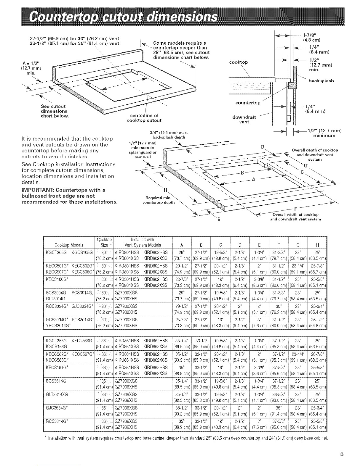
A=1/2"
(12,7ram}
rain,
Htisrecommendedthatthecooktop
andventcutoutsbedrawnonthe
countertopbeforemakingany
cutoutstoavoidmistakes.
SeeCooktopInstallationHnstrucfions
forcompHetecutoutdimensions,
Hocafiondimensionsandinstallation
details.
IMPORTANT:Countertopswitha
bulhosedfrontedge are not
recommended for these installations.
3/4"" (19.1 turn} max
backsplash depth
1/2"" (12.7 ram)
minimum to
splashguard or
rear wall
H
cooktop
X
countertop j
downdraft _Jf
vent
-- 1o7/8"
/4.8 cm)
1/4"
1&4 ram)
1/2"
(12,7 mm}
rain,
backsplash
1/4"
(&4 mm}
_1 I"_ 1/2'_,(1,2'mTummm )
Overall depth of cooktop
and downdraff vent
system
Coo_op Models
KGCT305G KGCSIO5G
KECC501G* KECCSO2G*
KECC507G* KECC5OSG*
KECSIOOG*
SCS3OO4G SCS3014G,
GLT3014G
RCC3024G* GJC3034G*
RCS3OO4G*RCS3014G*
YRCS3014G*
Cooktop
Size
30!'
(76.2ore)
80"
(76.2cm) KIRD801XSS
30" ' KIRDSO1HSS
(76.2cm)KIRDSOlXSS
30? GZ7930XGS
(76.2cm) GZ7930XHS
30'! GZ7930XGS
(76.2cm) GZ7930XHS
301' GZ7930XGS
(76.2cm) GZ7930XHS
Installedwith
VentSystemModels
KIRD801HSS KIRD802HSS
KIRDSOlXSS KIRDSO2XSS
KIRDSO1HSS KIRDSO2HSS
KIRDSO2XSS
KIRDSO2HSS
KIRDSO2XSS
A B C D E F G H
29" 27q/2" 19-5/8" 2q/8" 1-3/4" 31-3/8" 23" 25"
(73,7cm) (6&9 em) (49.8cm) (5.4 em) (4,4 cm) (7&7 cm) (58.4cm) (63,5 em)
29q/2" 27q/2" 20q/2" 2q/8" 2" 31q/2" 23-!/4" 25-7/8"
(74.9cm) (69,9cm) (52,1cm) (5,4 em) (5,1cm) (80,0 em) (59,1cm) (65,7em)
28-7/8" 27ol/2" 19" 2q/2" 3o3/8" 31q/2" 23" 25-5/8"
(73.3cm) (69,9em) (48,3cm) (6,4 cm) (8,6cm) (S&Ocm) (58,4cm) (65,1 em)
29" 27q/2" 19-5/8" 2q/8" 1-3/4" 31o3/8" 23" 25"
(73.7cm) (69,9em) (49,8cm) (5,4 em) (4,4cm) (79,7cm) (58,4cm) (63,5em)
29q/2" 27ol/2" 20q/2" 2" 2" 30" 23" 25-3/4"
(74.9cm) (69,9em) (52,1cm) (5,1 em) (5,1cm) (76,2em) (58,4cm) (65,4em)
28-7/8" 27q/2" 19" 2q/2" 3" 31q/2" 23" 25q/2"
(73.3cm) (69,9cm) (48,3cm) (6,4 em) (7,6cm) (S&Ocm) (58,4cm) (64,8em)
KGCT365G KECT366G
KGCS166G (9! .4 cm)
KECC562G* KECC567G* 36?
KECC568G* (91.4cm)
KECS161G* 36?
(9! .4 cm)
SCS3614G 36!i
(9! .4 cm)
GLT3614XG 36!i
(91.4cm)
GJC3634G* 36!I
(91.4cm)
RCS3614G* 36'_
(91.4cm)
KIRD861HSS KIRD862HSS 35q/4" 33-1/2 19_5/8" 2ol/8" 1-3/4" 37q/2" 23" 25"
KIRD861XSS KIRD862XSS (89,5cm) (8&9cm) (4&8cm) (5.4cm) (4,4cm) (9&3cm) (58.4cm) (63Scm)
KIRD861HSS KIRD862HSS 35q/2" 33q/2" 20q/2" 2q/8" 2" 37q/2" 23q/4" 26o7/8"
KIRD861XSS KIRD862XSS (90.2cm) (S&gcm) (52,1cm) (5,4em) (SJcm) (9&3cm) (59,1cm) (6&3em)
KIRD861HSS KIRD862HSS 35" 33q/2" 19" 2q/2" 3o3/8" 37-5/8" 23" 25-5/8"
KIRD861XSS KIRD862XSS (88.9cm) (S&gem) (48,3cm) (6,4em) (&6cm) (9&6cm) (58,4cm) (65,1em)
GZ7936XGS 35q/4" 33q/2" 19-5/8" 2q/8" 1-3/4" 37q/2" 23" 25"
GZ7936XHS (89.5cm) (85,9 cm) (49,8cm) (5,4 em) (4,4cm) (95,3em) (58,4cm) (63,5em)
GZ7936XGS 35-1/4" 33q/2" 19-5/8" 2q/8" 1-3/4" 36-5/8" 23" 25"
GZ7936XHS (89.5cm) (85,9cm) (49,8cm) (5,4 em) (4,4cm) (9&Ocm) (58,4cm) (63,5em)
GZ7936XGS 35q/2" 33q/2" 20q/2" 2" 2" 36" 23" 25-3/4"
GZ7936XHS (902 cm) (85,9cm) (52.1 cm) (5.1 em) (5,1cm) (91A cm) (58.4cm) (65,4 em)
GZ7936XGS 35" 33q/2" 19" 2q/2" 3" 37-5/8" 23" 25-5/8"
GZ7936XHS (88.9cm) (85,9 cm) (48,3cm) (6,4 em) (7,6cm) (95,6cm) (58,4cm) (65,1em)
* Installationwithventsystem requirescountertopandbase cabinetdeeper than standard25" (63.5cm) deepcountertopand 24" (61,0cm) deep basecabinet,
 Loading...