

KitchenAid KIRD801V, KIRD861V, KIRD862V User Manual
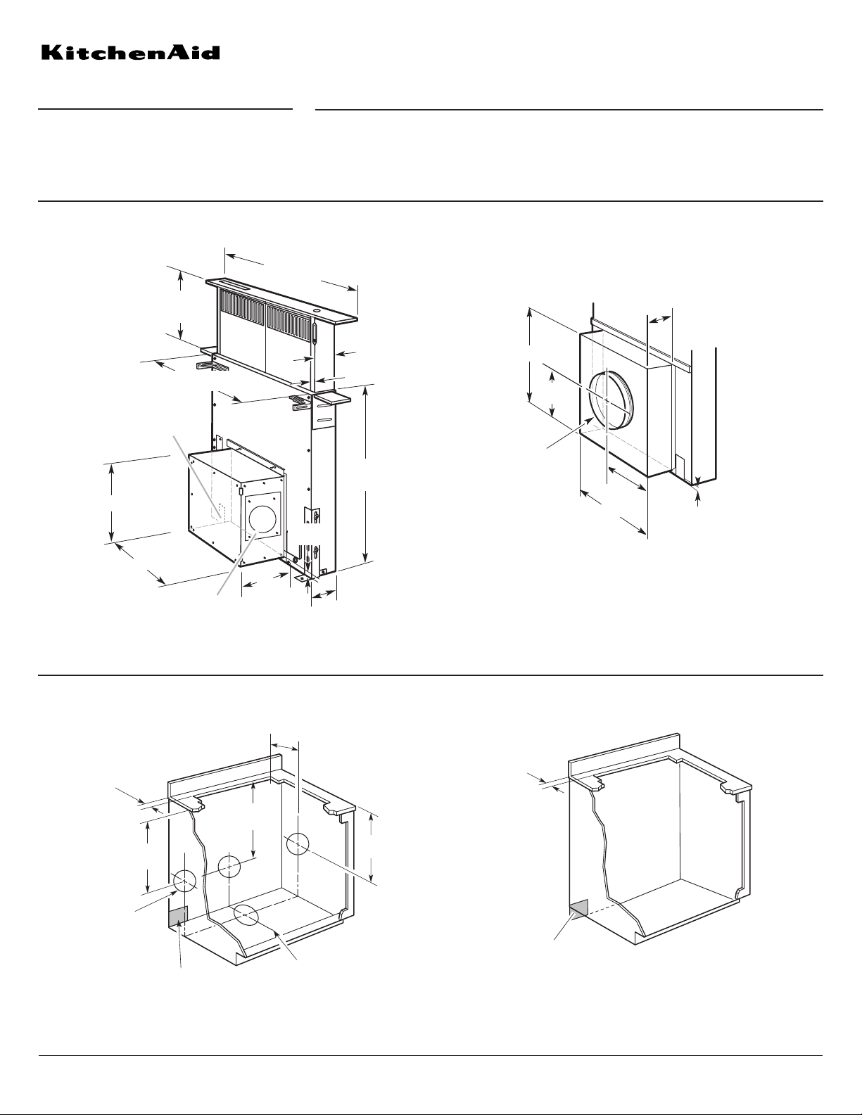
Top trim widths:
30¹⁄₄" (76.8 cm) for 30" (76.2 cm) vent
36¹⁄₄" (92.1 cm) for 36" (91.4 cm) vent
13¹⁄₂" (34.3 cm)
retractable
vent height
27" (68.6 cm) for 30" (76.2 cm) vent
33" (83.8 cm) for 36" (91.4 cm) vent
13" (33.0 cm)
9¹⁄₄"
(23.5 cm)
³⁄₄"
(1.9 cm)
2¹⁄₈" (5.4 cm)
28³⁄₄"
(73.0 cm)
³⁄₈" (0.95 cm)
1¹⁄₂" (3.8 cm)
13" (33.0 cm)
Interior-mounted blower motor model
Exterior-mounted blower motor model used with Part Number KPEC992M
¹⁄₄" (0.6 cm)
13" (33.0 cm)
6¹⁄₂"
(16.5 cm)
10" (25.4 cm)
diameter
vent collar
13" (33.0 cm)
6¹⁄₂"
(16.5 cm)
³⁄₄" (1.9 cm)
Terminal box cover
6" (15.2 cm)
diameter
vent collar
PRODUCT MODEL NUMBERS
PRODUCT DIMENSIONS
CABINET DIMENSIONS
KIRD801V
KIRD861V
KIRD862V
A 120-volt, 60-Hz, AC-only, 15-amp, fused electrical
cIrcuit is required. Use copper wire only.
30" (76.2 CM) and 36" (91.4 CM) Retractable Downdraft Vent System
Because Whirlpool Corporation policy includes a continuous commitment to improve
our products, we reserve the right to change materials and specifications without notice.
Dimensions are for planning purposes only. For complete details, see Installation
Instructions packed with product. Specifications subject to change without notice.
Ref. W10187117
11-06-08
®
ledom rotom rewolb detnuom-roiretxEledom rotom rewolb detnuom-roiretnI
A= ¹⁄₂" (12.7 mm)
minimum
21⁵⁄₁₆"
(54.1 cm)
All cutouts are
for 6" (15.2 cm)
diameter vent
system.
Centerline of cooktop cutout
23³⁄₄"
(60.3 cm)
21⁵⁄₁₆"
(54.1 cm)
Locate power
supply junction
box at lower
left hand
rear corner
of the cabinet.
7⁵⁄₈" (19.4 cm)
¹⁄₂" (12.7 mm)
minimum
Locate power
supply junction
box at lower
left hand
rear corner
of the cabinet.
ELECTRICAL REQUIREMENTS
Page 1 of 3
30" (76.2 CM) and 36" (91.4 CM) Retractable Downdraft Vent System
®
Because Whirlpool Corporation policy includes a continuous commitment to improve
our products, we reserve the right to change materials and specifications without notice.
Dimensions are for planning purposes only. For complete details, see Installation
Instructions packed with product. Specifications subject to change without notice.
Ref. W10187117
11-06-08
Page 2 of 3
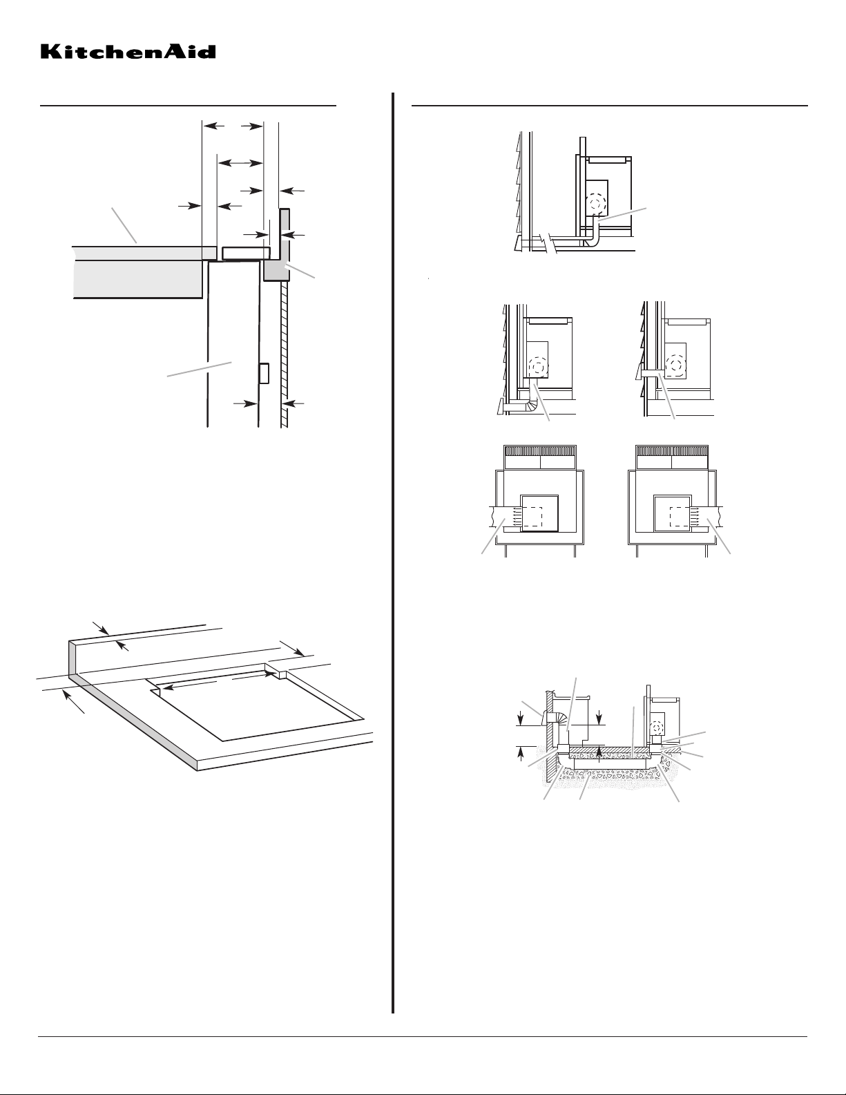
COUNTERTOP CUTOUT DIMENSIONS
A. Downdraft vent
B. Cooktop
C. Measurement of cooktop rear overhang.
D. D = Measurement of cooktop rear overhang (C) +
1
¹³⁄₁₆
" [46.2 mm] (E)
E. 1
¹³⁄₁₆
" (46.2 mm)
F. ½" (12.7 mm) minimum
G. ¼" (6.4 mm) minimum
H. Countertop and backsplash
I. ½" (12.7 mm) minimum
A
B
C
E
H
D
I
G
F
VENTING REQUIREMENTS
A. ½" (12.7 mm) minimum to backsplash or
rear wall
B.
³⁄₄
" (19.1 mm) maximum backsplash depth
C. 27
¹⁄₂
" (69.9 cm) on 30" (76.2 cm) models
33
¹⁄₂
" (85.9 cm) on 36" (91.4 cm) models
D. D = Measurement of cooktop rear overhang
+ 1
¹³⁄₁₆
" (46.2 mm)
A
B
C
D
Island location
Built-in cabinet locations
A. Down vent
A. Down vent
B. Rear vent
C. Left vent
D. Right vent
A
B
C
D
A
Island Location
Vent system installed under a concrete slab using PVC
sewer pipe.
A. Wall cap
B. 6" (15.2 cm) round metal vent
C. 16" (40.6 cm) maximum
D. 6" (15.2 cm) round PVC sewer pipe
E. 6" (15.2 cm) round metal vent
F. 6" (15.2 cm) round PVC coupling
G. Concrete slab
H. 6" (15.2 cm) round PVC sewer pipe
I. 6" (15.2 cm) round 90° PVC sewer pipe elbow
J. Tightly pack gravel or sand completely around pipe.
K. 6" (15.2 cm) round 90° PVC sewer pipe elbow
L. 6" (15.2 cm) round PVC coupling
M. 12" (30.5 cm) minimum
A
B
C
D
E
F
G
H
I
J
K
L
M
 Loading...