

KitchenAid KESC300BWH1, KESC300BBL1, KESC300BAL1 Installation Guide
tche A-d
HOME APPLIANCES
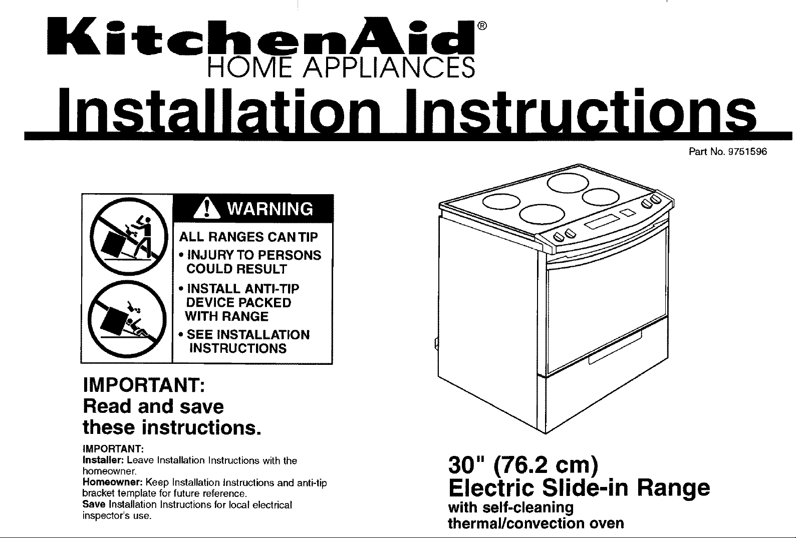
ALL RANGES CAN TIP
• INJURY TO PERSONS
COULD RESULT
• INSTALL ANTI-TIP
DEVICE PACKED
WITH RANGE
Pa_ No. 9751596
• SEE INSTALLATION
INSTRUCTIONS
IMPORTANT:
Read and save
these instructions.
IMPORTANT:
Installer: Leave Installation Instructions with the
homeowner.
Homeowner: Keep Installation Instructions and anti-tip
bracket template for future reference.
Save Installation Instructions for local electrical
inspector's use.
30" (76.2 cm)
Electric Slide-in Range
with self-cleaning
thermal/convection oven
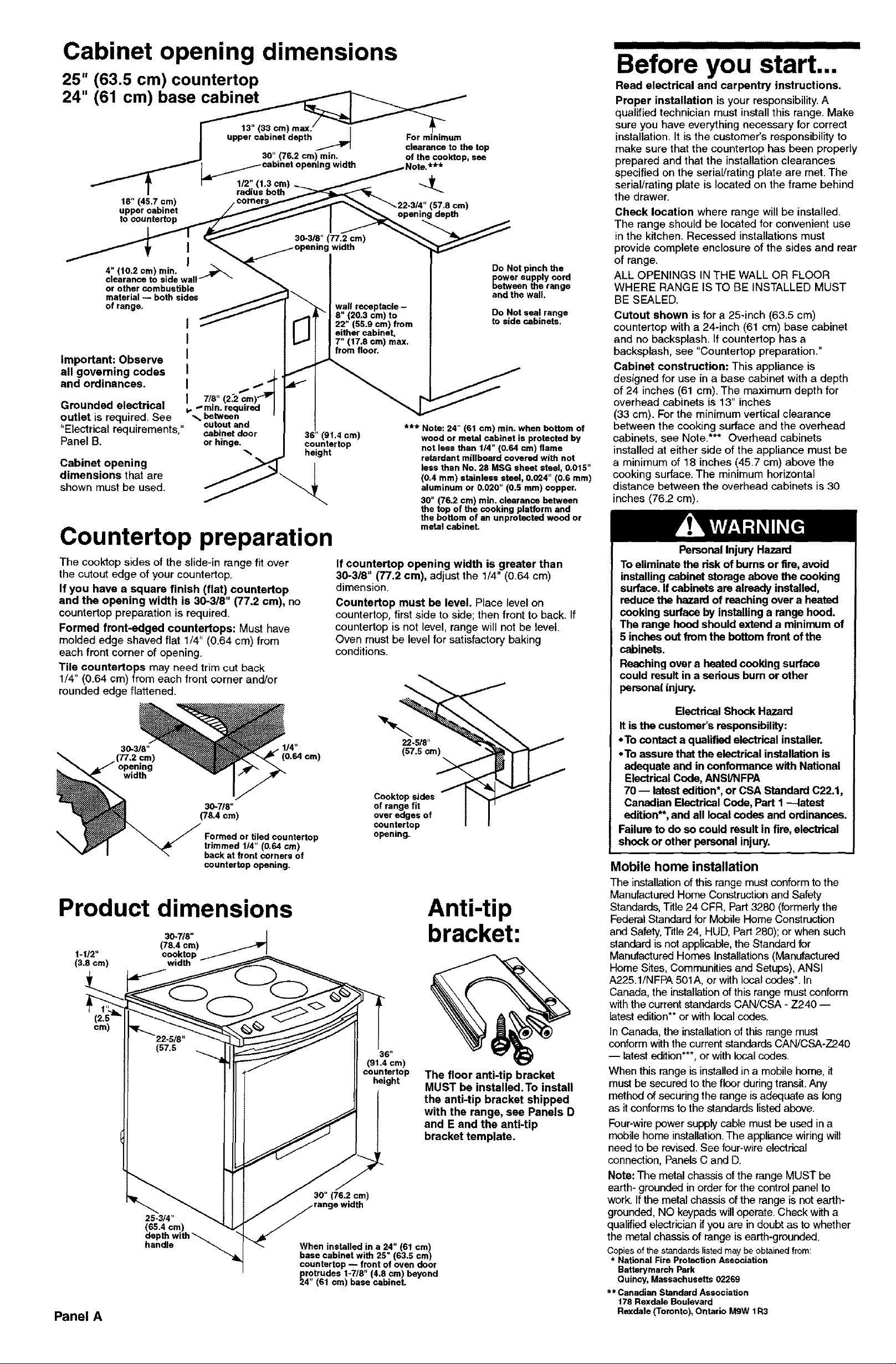
Cabinet opening dimensions
25" (63.5 cm) countertop
24" (61 cm) base
J upper cabinet depth _J For minimum
I .... e|..Jancat?thetop
_J 30." (76.2 cm)rnin.., of the cooktop, sea
18" (45.7cm!, / c°_/_,,...,.,,1"'"_ _22-3/4" (67.8 cm)
_loPP_[,c_,_tne' _-/// I _ opening depth
outlet is required. See _ between
"Electrical
re_u,rements,"-:" cabinet door
Panel B. or hinge.
Cabinet opening
dimensions that are
shown must be used.
cutout and
36" (91.4 era)
-%
counter top
height
Countertop preparation
The cooktop sides of the slide-in range fit over
the cutout edge of your countertop.
If you have a square finish (flat) countertop
and the opening width is 30-318" (77,2 cm), no
countertop preparation is required.
Formed front-edged countertops: Must have
molded edge shaved flat 1/4" (0.64 cm) from
each front corner of opening.
Tile countertops may need trim cut back
1/4" (0.64 cm) from each front corner and/or
rounded edge flattened.
(0.64 cm)
30-718"
(78.4 cm)
Formed or tiled countertop
trimmed tJ4" (0.64 cm)
back at front corners of
counter top opening.
If countertop opening width is greater than
30-318" (77,2 cm), adjust the 1/4" (0.64 cm)
dimension.
Counterfop must be level. Place level on
countertop, first side to side; then front to back. If
countertop is not level, range will not be level.
Oven must be level for satisfactory baking
conditions.
Product dimensions
30-z/6" |
t-t12" cooktop / '
(3.6 cm) width
Panel A
(78.4 cm)
25-3/4"
_65.4 ore)
epth with
handle "_
30" (76.2 cm)
) width
When installed in a 24" (61 cm)
base cabinet with 25 (63.5 cm)
countertop -- front of oven door
_4rotrudea 1-7/8" (4,8 cm) beyond
" (61 cm) base cabineL
Cooktop sides
of range fit
over edges of
countertop
opening.
36 _
(91.4 cm)
countertop
height
*** Note: 24" (61 cm) min. when bottom of
wood or metal cabinet is protected by
not less than 1/4" (0.64 cm) flame
retardant miflboard covered with not
less than No. 28 MSG sheet steel, 0.015"
(0.4 ram) stainless steel, 0.024" (0.6 ram)
aluminum or 0.020" (0.6 ram) copper,
30" (76.2 cm) min. clearance between
the top of the cooking platform and
the bottom of an unprotected wood or
metal cabinet.
22-518"
(57.5 cm)
Anti-tip
bracket:
The floor anti-tip bracket
MUST be installed. To install
the anti-tip bracket shipped
with the range, see Panels D
and E and the anti-tip
bracket template.
Before you start...
Read electrical and carpentry instructions.
Proper installation is your responsibility.A
qualified technician must install this range. Make
sure you have everything necessary for correct
installation. It is the customer's responsibility to
make sure that the countertop has been properly
prepared and that the installation clearances
specified on the seriaVrating plate are met. The
serial/rating plate is located on the frame behind
the drawer.
Check location where range will be installed.
The range should be located for convenient use
in the kitchen. Recessed installations must
provide complete enclosure of the sides and rear
of range.
ALL OPENINGS IN THE WALL OR FLOOR
WHERE RANGE ISTO BE INSTALLED MUST
BE SEALED.
Cutout shown is for a 25-inch (63.5 cm)
countertop with a 24-inch (61 cm) base cabinet
and no backsplash. If countertop has a
backsplash, see "Countertop preparation."
Cabinet construction: This appliance is
designed for use in a base cabinet with a depth
of 24 inches (61 cm). The maximum depth for
overhead cabinets is 13" inches
(33 cm). For the minimum vertical clearance
between the cooking surface and the overhead
cabinets, see Note.*** Overhead cabinets
installed at either side of the appliance must be
a minimum of 18 inches (45.7 cm) above the
cooking surface. The minimum horizontal
distance between the overhead cabinets is 30
inches (76.2 cm).
Personal Injury Hazard
To eliminate the dsk of burns or fire,avoid
installing cabinet storage above the cooking
surface, If cabinets are already installed,
reduce the hazard of reaching over a heated
cooking surface by installing a range hood.
The range hood should extend a minimum of
5 inches out from the bottom front ofthe
cabinets.
Reaching over a heated cooking surface
could result in a serious burn or other
psmonal injury.
Electrical Shock Hazard
It is the customer's responsibility:
• To contact a qualified electrical installer.
• To assure that the electrical installation is
adequate and in confonnanca with National
Electrical Code, ANSI/NFPA
70 -- latest edition*, or CSA Standard C22,1,
Canadian Eleetdcal Code, Part I --latest
edition**, and all local codes and ordinances.
Failure to do so could result in fire, electrical
shock or other personal injury.
Mobile home installation
The installation of this range must conform to the
Manufactured Home Construction and Safety
Standards, Title 24 CFR, Part 3280 (formerly the
Federal Standard for Mobile Home Construction
and Safety, Title 24, HUD, Part 280); or when such
standard is not applicable, the Standard for
Manufactured Homes Installations (Manufactured
Home Sites, Communities and Setups), ANSI
A225.1/NFPA 501A, or with local codes*. In
Canada, the installation of this range must conform
with the current standards CAN/CSA - Z240 --
latest edition** or with local codes.
In Canada, the installation of this range must
conform withthe current standards CAN/CSA-Z240
-- latest edition***, or with local codes.
When this range is installed in a mobile home, it
must be secured to the floor during transit. Any
method of securing the range isadequate as long
as it conforms tothe standards listed above.
Four-wire power supply cable must be used in a
mobile home installation. The appliance wiring will
need to be revised. See four-wire electrical
connection, Panels C and D.
Note: The metal chassis of the range MUST be
earth- grounded in order for the control panel to
work. If the metal chassis of the range is not earth-
grounded, NO keypads will operate. Check with a
qualified electrician if you are in doubt as to whether
the metal chassis of range is earth-grounded.
Copiesof the standards listed maybe obtainedfrom:
* NationalFire ProtectionAssociation
BattarymarchPark
Quincy,Massachusetts 02269
** Canadian StandardAssociation
178 Rexdale Boulevard
Rexdale(Toronto),Ontario MgW tR3
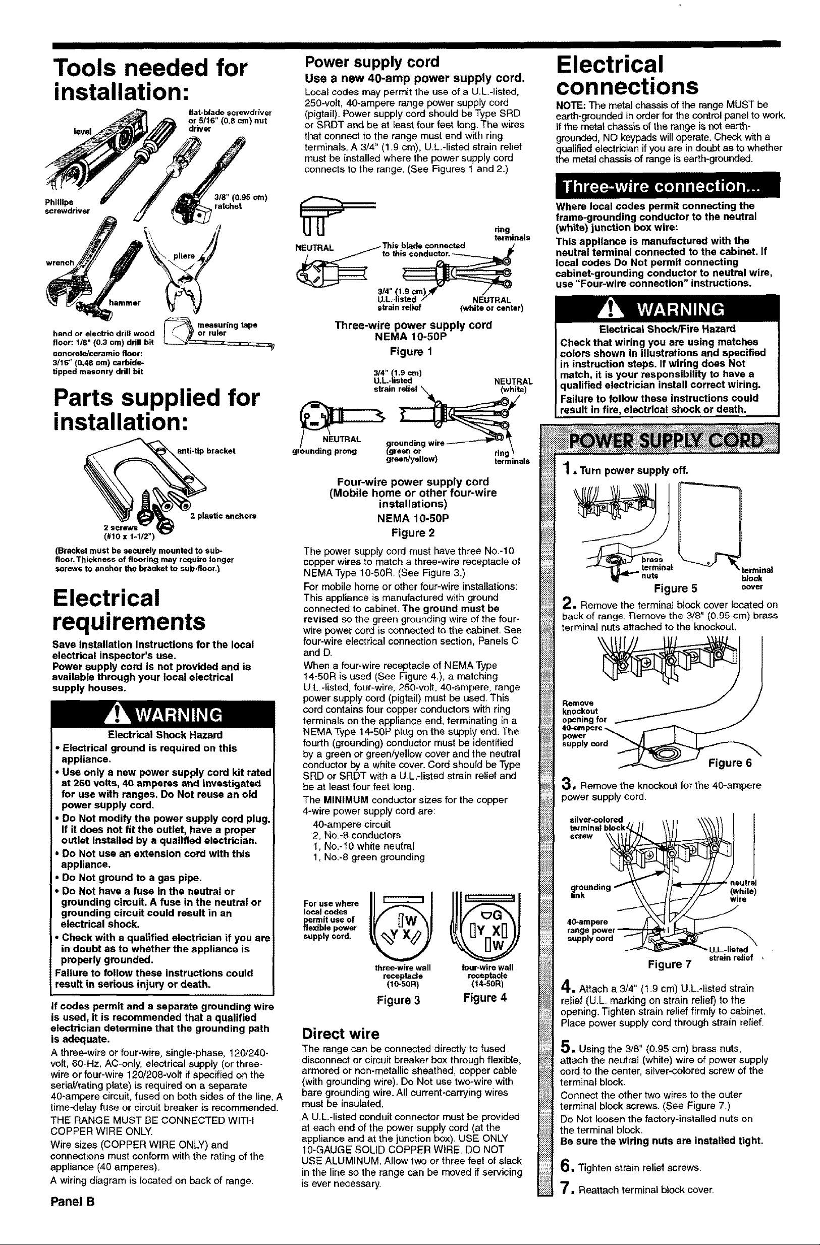
Tools needed for
installation:
flat-blade screwdriver
or 5/16" (0,8 cm) nut
level
driver
Power supply cord
Use a new 40-amp power supply cord.
Local codes may permit the use of a U.L.-listed,
250-volt, 40-ampere range power supply cord
(pigtail). Power supply cord should be Type SRD
or SRDT and be at least four feet long. The wires
that connect to the range must end with ring
terminals. A 3/4" (1.9 cm), U.L.-listed strain relief
must be installed where the power supply cord
connects to the range. (See Figures 1 and 2.)
Electrical
connections
NOTE: The metal chassis of the range MUST be
earth-grounded in order for the control panel to work,
If the metal chassis of the range is not earth-
grounded, NO keypads will operate. Check with a
qualified electrician ifyou are in doubt as to whether
the metal chassis of range is earth-grounded.
Phillips ratchet
screwdriver
wrench
hand or electric drill wood
floor: 1/8" (0,3 cm) drill bit
concrete/ceramic floor:
3/16" (0.48 cm) carbide-
tipped masonry drill bit
318" (0.95 ¢m)
measuringtape
Parts supplied for
installation:
anti-tip bracket
2 plastic anchors
(#10 x 1-1/2")
(Bracket must be securely mounted to sub-
floor, Thickness of flooring may require longer
screws to anchor the bracket to sub-floor,)
Electrical
requirements
Save Installation Instructions for the local
electrical inspector's use.
Power supply cord is not provided and is
available through your local electrical
supply houses.
Electrical Shock Hazard
• Electrical ground is required on this
appliance,
• Use only a new power supply cord kit rated
at 250 volts, 40 amperes and investigated
for use with ranges. Do Not reuse an old
power supply cord.
• Do Not modify the power supply cord plug.
If it does not fit the outlet, have a proper
outlet installed by a qualified electrician.
• Do Not use an extension cord with this
appliance.
• Do Not ground to a gas pipe.
• Do Not have a fuse in the neutral or
grounding circuit. A fuse in the neutral or
grounding circuit could result in an
electrical shock.
• Check with a qualified electrician if you are
in doubt as to whether the appliance is
properly grounded,
Failure to follow these instructions could
result in serious injury or death.
If codes permit and a separate grounding wire
is used, it is recommended that a qualified
electrician determine that the grounding path
is adequate.
A three-wire or four-wire, single-phase, 120/240-
volt, 60-Hz, AC-onty, electrical supply (or three-
wire or four-wire 120/208-volt if specified on the
serial/rating plate) is required on a separate
40-ampere circuit, fused on both sides of the line. A
time-delay fuse or circuit breaker is recommended.
THE RANGE MUST BE CONNECTED WITH
COPPER WIRE ONLY.
Wire sizes (COPPER WIRE ONLY) and
connections must conform with the rating of the
appliance (40 amperes).
A wiring diagram is located on back of range.
Panel B
ring
terminals
NEUTRAL _1 This blade connected _/
_to thi_
3,,(,;; .=,/,.=.T
U.L-listed NEUTRAL
strain relief (white or center)
Three-wire power supply cord
NEMA 10-50P
Figure 1
3/4" (1.9 cm)
U.L.4isted NEUTRAL
strain _e)
Four-wire power supply cord
(Mobile home or other four-wire
installations)
NEMA 10-50P
Figure 2
The power supply cord must have three No.-lO
copper wires to match a three-wire receptacle of
NEMA Type 10-50R. (See Figure 3.)
For mobile home or other four-wire installations:
This appliance is manufactured with ground
connected to cabinet. The ground must be
revised so the green grounding wire of the four-
wire power cord is connected to the cabinet. See
four-wire electrical connection section, Panels C
and D.
When a four-wire receptacle of NEMA Type
14-50R is used (See Figure 4.), a matching
U.L.-listed, four-wire, 250-volt, 40-ampere, range
power supply cord (pigtail) must be used. This
cord contains four copper conductors with ring
terminals on the appliance end, terminating in a
NEMA Type 14-50P plug on the supply end. The
fourth (grounding) conductor must be identified
by a green or green/yellow cover and the neutral
conductor by a white cover. Cord should be Type
SRD or SRDT with a U.L.-listed strain relief and
be at least four feet long.
The MINIMUM conductor sizes for the copper
4-wire power supply cord are:
40-ampere circuit
2, No.-8 conductors
1, No.-10 white neutral
1, No.-8 green grounding
For use where
local codes
_lermit use of
exible power
supply cord.
three-wire wall
receptade
(10-50R)
Figure 3
four-wirewall
receptacle
(14-S0R)
Figure 4
Direct wire
The range can be connected directly to fused
disconnect or circuitbreaker box through flexible,
armored or non-metallic sheathed, copper cable
(with grounding wire). Do Not use two-wire with
bare grounding wire. All current-carrying wires
must be insulated.
A U.L-listed conduit connector must be provided
at each end of the power supply cord (at the
appliance and at the junction box). USE ONLY
10-GAUGE SOLID COPPER WIRE. DO NOT
USE ALUMINUM. Allow two or three feet of slack
in the line so the range can be moved ifservicing
is ever necessary.
Where local codes permit connecting the
frame-grounding conductor to the neutral
(white) junction box wire:
This appliance is manufactured with the
neutral terminal connected to the cabinet. If
local codes Do Not permit connecting
cabinet-grounding conductor to neutral wire,
use "Four-wire connection" instructions.
Electrical Shock/Fire Hazard
Check that wiring you are using matches
colors shown in illustrations and specified
in instruction steps. If wiring does Not
match, it is your responsibility to have a
qualified electrician install correct wiring.
Failure to follow these instructions could
result in fire, electrical shock or death.
1.Turn power supply off.
I _ terminal
block
Figure 5 cover
2 • Remove the terminal block cover located on
back of range. Remove the 3/8" (0.95 cm) brass
terminal nuts attached to the knockout.
Remove l
knockout /
openingfor
40-am pare _
power _ A I F
supply cord _
Figure 6
3, Remove the knockout for the 40-ampere
power supply cord.
silver-colored
_rounding
nk
40-ampere
Figure 7
(white)
wire
,U.L,-listed
strain relief
4.Attach a 3/4" (1.9 cm) U.L.-listed strain
relief (U.L. marking on strain relief) to the
opening. Tighten strain relief firmly to cabinet.
Place power supply cord through strain relief.
5. Using the 3/8" (0.95 cm) brass nuts,
attach the neutral (white) wire of power supply
cord to the center, silver-colored screw of the
terminal block.
Connect the other two wires to the outer
terminal block screws. (See Figure 7.)
Do Not loosen the factory-installed nuts on
the terminal block.
Be sure the wiring nuts are installed tight.
6,Tighten strain relief screws.
7, Reattach terminal block cover.
 Loading...