


KECD807XBL

30" (76.2 CM) AND 36" (91.4 CM) ELECTRIC
IMPORTANT:
Save for local electrical inspector's use.
IMPORTANT :
À conserver pour consultation par l'inspecteur local des installations électriques.
DOWNDRAFT COOKTOP
INSTALLATION INSTRUCTIONS
INSTRUCTIONS D'INSTALLATION DE LA TABLE DE
CUISSON ÉLECTRIQUE AVEC ASPIRATION
PAR LE BAS DE 30" (76,2 CM) ET 36" (91,4 CM)
Table of Contents/Table des matières
COOKTOP SAFETY........................................................................2
INSTALLATION REQUIREMENTS ................................................2
Tools and Parts ............................................................................2
Location Requirements ................................................................3
Venting Requirements..................................................................4
Venting Methods ..........................................................................5
Electrical Requirements ...............................................................7
INSTALLATION INSTRUCTIONS ..................................................7
Prepare Cooktop..........................................................................7
Install Foam Strip..........................................................................8
Rotate Blower - Required On Some Installations........................8
Install Cooktop .............................................................................8
Make Electrical Connection .........................................................9
Complete Installation..................................................................10
SÉCURITÉ DE LA TABLE DE CUISSON .................................11
EXIGENCES D'INSTALLATION................................................11
Outils et pièces........................................................................11
Exigences d’emplacement...................................................... 12
Exigences concernant l'évacuation ........................................14
Méthodes d'évacuation...........................................................15
Spécifications électriques ....................................................... 16
INSTRUCTIONS D’INSTALLATION .........................................17
Préparation de la table de cuisson .........................................17
Installation de la bande de mousse........................................17
Rotation du ventilateur - Obligatoire pour certaines
installations..............................................................................18
Installation de la table de cuisson...........................................18
Raccordement électrique........................................................19
Achever l'installation ...............................................................20
W10439665B
COOKTOP SAFETY
You can be killed or seriously injured if you don't immediately
You
can be killed or seriously injured if you don't
follow
All safety messages will tell you what the potential hazard is, tell you how to reduce the chance of injury, and tell you what can
happen if the instructions are not followed.
Your safety and the safety of others are very important.
We have provided many important safety messages in this manual and on your appliance. Always read and obey all safety
messages.
This is the safety alert symbol.
This symbol alerts you to potential hazards that can kill or hurt you and others.
All safety messages will follow the safety alert symbol and either the word “DANGER” or “WARNING.”
These words mean:
follow instructions.
instructions.
DANGER
WARNING
INSTALLATION REQUIREMENTS
Tools and Parts
Gather the required tools and parts before starting installation.
Read and follow the instructions provided with any tools listed
here.
Tools ne eded
■ Tape measure
■ Flat-blade screwdriver
■ Phillips head screwdriver
■ Drill
■ Level
■ 6" socket extension
■ Marker or pencil
■ Pliers
■ ¼" drill bit
■ Jigsaw
■ Ratchet with ³⁄₈"socket
Parts supplied
■ Vent grille
■ Pre-filter
Parts needed
■ A UL listed or CSA approved strain relief for ⁷⁄₈" (2.2 cm)
knockout.
■ A UL listed or CSA approved conduit connector for
¹⁄₂" (1.3 cm) trade-size metal-clad conduit
■ UL listed wire connectors
■ Metal ducting
■ Wall cap
6" (15.2 cm) Round Surface Wall Cap Damper
Order Part Number A406
5" (12.7 cm) Round Surface Wall Cap Damper
Order Part Number A405
3¼" x 10" (8.3 x 25.4 cm) Surface Wall Cap Damper
Order Part Number A403
To order, see the “Assistance or Service” section of the Use
and Care Guide.
■ Vent clamps
Check local codes. Check existing electrical supply. See
“Electrical Requirements” section.
It is recommended that all electrical connections be made by a
licensed, qualified electrical installer.
2
Location Requirements
A
B
C
A
B
C
D
F
E
G
H
B
C
A
A
B
C
E
D
F
G
H
IMPORTANT: Observe all governing codes and ordinances.
When installing cooktop, use minimum dimensions given.
■ To eliminate the risk of burns or fire by reaching over the
heated surface units, cabinet storage space located above
the surface units should be avoided. If cabinet storage is to
be provided, the risk can be reduced by installing a range
hood that projects horizontally a minimum of 5" (12.7 cm)
beyond the bottom of the cabinets.
■ Use the countertop opening dimensions that are given with
these Installation Instructions. Given dimensions are
minimum clearances and provide 0" (0 cm) clearance.
■ Grounded electrical supply is required. See “Electrical
Requirements” section.
■ If cabinet has drawers, drawers will need to be removed and
drawer fronts installed on front of cabinet.
IMPORTANT: An under-counter built-in oven cannot be installed
under this product.
Product Dimensions
30" (76.2 cm) Cooktop - for standard and electric models
36" (91.4 cm) Cooktop - for standard and electric models
A. Model/serial rating/clearance plate location
B. 21" (53.4 cm) screw head to screw head
C. 22" (55.9 cm) without stainless steel trim or
21³⁷⁄₆₄" (54.8 cm) with stainless steel trim
A. Model/serial rating/clearance plate location
B. 21" (53.4 cm) screw head to screw head
C. 22" (55.9 cm) without stainless steel trim or
21³⁷⁄₆₄" (54.8 cm) with stainless steel trim
A. 29³⁄₄" (75.6 cm)
B. 12¹⁄₂" (31.8 cm)
centerline of product to
edge of burner box
C. 12¹⁄₂" (31.8 cm)
D. 28³⁄₈" (72.1 cm)
E. 12¹⁄₂" (31.8 cm)
F. 2" (5.1 cm) recommended minimum
cabinet to motor clearance
G. 18" (45.7 cm)
H. 4⁵⁄₈" (11.8 cm)
A. 35¹¹⁄₃₂" (89.8 cm)
B. 12⁷⁄₈" (32.7 cm) centerline of
product to edge of burner box
C. 12⁷⁄₈" (32.7 cm)
D. 34¹⁄₈" (86.7 cm)
E. 12¹⁄₂" (31.8 cm)
F. 8 ¹⁷⁄₆₄" (21.0 cm)
recommended minimum
cabinet to motor clearance
G. 18" (45.7 cm)
H. 4⁵⁄₈" (11.8 cm)
3
Cabinet Dimensions
D
A
E
I
J
K
G
H
L
C
F
B
A
B
C
D
E
F
G
H
I
J
A. 30" (76.2 cm) on 30" (76.2 cm) models
36" (91.4 cm) on 36" (91.4 cm) models
B. Combustible area above countertop (shown by dashed box above)
C. 30" (76.2 cm) minimum clearance between top of cooktop platform
and bottom of uncovered wood or metal cabinet (24" [61 cm]
minimum clearance if bottom of wood or metal cabinet is covered
by not less than ¹⁄₄" [0.6 cm] flame retardant millboard covered with
not less than No. 28 MSG sheet steel, 0.015" [0.04 cm] stainless
steel, or 0.024" [0.06 cm] aluminum or 0.020" [0.05 cm] copper)
D. 13" (33 cm) recommended upper cabinet depth
E. 2" (5.1 cm)
F. 2 1 ¹⁄₈" (53.7 cm)
G. 18" (45.7 cm) minimum clearance from upper cabinet to countertop
within minimum horizontal clearances to cooktop
H. Junction box or outlet; 12" (30.5 cm) minimum from bottom of
countertop
I. Junction box or outlet; 10" (25.4 cm) from right-hand side of
cabinet
J. 28⁷⁄₈" (73.3 cm) on 30" (76.2 cm) models
34⁹⁄₁₆" (87.8 cm) on 36" (91.4 cm) models
K. 2½" (6.4 cm) minimum distance to nearest left and right side
combustible surface above cooktop
L. 1½" (3.8 cm) minimum clearance between back wall and
countertop
NOTES: After making the countertop cutout, some installations
may require notching down the base cabinet side walls to clear
the cooktop base. To avoid this modification, use a base cabinet
with sidewalls wider than the cutout.
■ A minimum side clearance of 6" (15.2 cm) is recommended
between side of cooktop and side wall for maximum
ventilation performance.
■ A minimum clearance of 2" (5.1 cm) is recommended
between the motor/blower and cabinet for proper cooling. A
6" (15.2 cm) clearance is recommended for servicing access.
Cutout Dimensions
A. 28⁷⁄₈" (73.3 cm) maximum on 30" (76.2 cm) models
34⁹⁄₁₆" (87.8 cm) maximum on 36" (91.4 cm) models
B. 21¹⁄₈" (53.7 cm) maximum on both 30" (76.2 cm) and 36" (91.4 cm)
models
C. 8¹⁹⁄₃₂" (21.8 cm) on 30" (76.2 cm) models
15⁷⁄₁₆" (39.2 cm) on 36" (91.4 cm) models
D. 6¹⁹⁄₆₄" (16.0 cm) on both 30" (76.2 cm) and 36" (91.4 cm) models
E. 2" (5.1 cm) minimum space to front edge of cooktop
F. Floor exhaust option
G. 6¹⁄₈" (15.6 cm) for 6" (15.2 cm) vent system
5¹⁄₈" (13 cm) for 5" (12.7 cm) vent system
H. 8¹⁹⁄₃₂" (21.8 cm) on 30" (76.2 cm) models
15⁷⁄₁₆" (39.2 cm) on 36" (91.4 cm) models
I. 16" (40.6 cm) on both 30" (76.2 cm) and 36" (91.4 cm) models
J. Wall exhaust option
Venting Requirements
IMPORTANT: This cooktop must be exhausted outdoors.
■ Do not terminate the vent system in an attic or other enclosed
area.
■ Use a vent cap.
■ Vent system must terminate to the outside.
■ Use only a 6" (15.2 cm) diameter round or 3¼" x 10"
(8.3 x 25.4 cm) rectangular vent except as follows: For
electric cooktops, a 5" (12.7 cm) diameter round vent may be
used for venting straight out the back of the cooktop and
directly through the wall for 10 ft (3.0 m) or less.
■ Before making cutouts, make sure there is proper clearance
within the wall or floor for the exhaust vent.
■ Do not cut a joist or stud unless absolutely necessary. If a
joist or stud must be cut, then a supporting frame must be
constructed.
■ The size of the vent should be uniform.
■ The vent system must have a damper. If roof or wall cap has a
damper, do not use damper supplied with the range hood.
■ Use vent clamps to seal all joints in the vent system.
■ Use caulking to seal exterior wall or roof opening around the
cap.
■ Determine which venting method is best for your application.
4
For Best Performance:
A
B
A
B
A
B
A
B
A
B
C
D
E
F
G
I
J
H
K
L
M
N
■ Use 26-gauge minimum galvanized or 25-gauge minimum
aluminum metal vent. Poor quality pipe fittings can reduce
airflow. Flexible metal vent is not recommended.
NOTE: Local codes may require a heavier gauge material.
■ Metal duct may be reduced to 30-gauge galvanized steel or
26-gauge aluminized steel if allowed by local codes. This
reduction is based on information in the International
Residential Codes Section M1601.1 (2006 edition).
■ Do not install 2 elbows together.
■ Use no more than three 90° elbows.
■ If an elbow is used, install it as far away as possible from the
hood’s vent motor exhaust opening.
■ Make sure there is a minimum of 18" (45.7 cm) of straight
vent between the elbows if more than one elbow is used.
■ Elbows too close together can cause excess turbulence that
reduces airflow.
■ Do not use a 5" (12.7 cm) elbow in a 6" (15.2 cm) or 3¹⁄₄" x 10"
(8.3 x 25.4 cm) system.
■ Do not reduce to a 5" (12.7 cm) system after using
6" (15.2 cm) or 3¹⁄₄" x 10" (8.3 x 25.4 cm) fittings.
■ Avoid forming handmade crimps. Handmade crimps may
restrict airflow.
■ Use a vent cap for proper performance. If an alternate wall or
roof cap is used, be certain the cap size is not reduced and
that it has a back draft damper.
■ Use vent clamps to seal all joints in the vent system.
■ Use caulking to seal exterior wall or roof opening around the
cap.
The length of vent system and number of elbows should be kept
to a minimum to provide efficient performance.
The maximum equivalent length of the vent system is 60 ft
(18.3 m). For altitudes above 4,500 ft (1372 m), reduce
recommended vent run by 20% for best performance.
Cold Weather Installations
An additional back draft damper should be installed to minimize
backward cold air flow and a thermal break installed to minimize
conduction of outside temperatures as part of the vent system.
The damper should be on the cold air side of the thermal break.
Makeup Air
Local building codes may require the use of makeup air systems
when using ventilation systems greater than specified CFM of air
movement. The specified CFM varies from locale to locale.
Consult your HVAC professional for specific requirements in your
area.
Venting Methods
Common venting methods are shown for a counter-mounted
downdraft cooktop. The cooktop may be vented through the wall
or floor.
Option 1 - Roof Venting Option 2 - Wall Venting
A. Roof cap
B. 6" (15.2 cm) round roof venting
Option 3 - Venting Between
Floor Joist
A. Wall cap
B. 6" (15.2 cm) round wall venting
Concrete Slab Installations Exhaust Through Window Well
A. 6" (15.2 cm) round wall venting
B. Wall cap
Option 4 - Venting behind
Cabinet Kick Plate
A. Wall cap
B. 6" (15.2 cm) round wall venting
A. Wall cap
B. 12" (30.5 cm) minimum
C. Concrete slab
D. 6" (15.2 cm) round PVC sewer pipe
E. 5" to 6" (12.7 cm to 15.2 cm)
transition
F. 6" (15.2 cm) round metal duct
G. 6" (15.2 cm) round PVC coupling
H. 6" (15.2 cm) round PVC sewer pipe
I. 6" (15.2 cm) round 90°
PVC sewer pipe elbow
J. Tightly pack gravel or sand
completely around pipe.
K. 42 ft (12.8 m) max.
L. 6" (15.2 cm) round
PVC coupling
M. 6" (15.2 cm) minimum
N. Window well
5
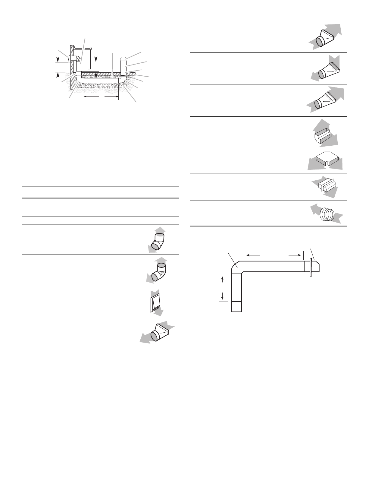
Concrete Slab Installations - Exhaust Through Wall
A
B
C
D
E
F
G
H
I
J
M
K
N
O
L
90˚ elbow
2 ft
(0.6 m)
6 ft (1.8 m)
wall cap
6" (15.2 cm) to 3¹⁄₄" x 10"
(8.3 cm x 25.4 cm) transition
1 ft
(0.3 m)
A. Wall cap
B. 6" (15.2 cm) round metal vent
C. 16" (40.6 cm) maximum
D. 6" (15.2 cm) round PVC
sewer pipe
E. 5" to 6" (12.7 cm to 15.2 cm)
transition
F. 6" (15.2 cm) round
metal duct
G. 6" (15.2 cm) round
PVC coupling
H. Concrete slab
I. 6" (15.2 cm) round PVC
sewer pipe
J. 6" (15.2 cm) round 90°
PVC sewer pipe elbow
K. Tightly pack gravel or sand
completely around pipe.
L. 30 ft (9.1 m) max.
M. 6" (15.2 cm) round 90°
PVC sewer pipe elbow
N. 6" (15.2 cm) round PVC
coupling
O. 12" (30.5 cm) minimum
Calculating Vent System Length
To calculate the length of the system you need, add the
equivalent feet (meters) for each vent piece used in the system.
Vent Piece 6" (15.2 cm) Round
45° elbow 2.5 ft
(0.8 m)
3¹⁄₄" x 10" (8.3 cm x 25.4 cm)
to 6" (15.2 cm) 90° elbow
transition
6" (15.2 cm) to 3¹⁄₄" x 10"
(8.3 cm x 25.4 cm) 90° elbow
transition
3¹⁄₄" x 10" (8.3 cm x 25.4 cm)
90° elbow
3¹⁄₄" x 10" (8.3 cm x 25.4 cm)
flat elbow
3¹⁄₄" x 10" (8.3 cm x 25.4 cm)
wall cap
5" to 6" (12.7 cm to 15.2 cm)
transition
Example vent system
9.0 ft
(2.7 m)
5.0 ft
(1.5 m)
5.0 ft
(1.5 m)
12.0 ft
(3.7 m)
0.0 ft
(0.0 m)
1 ft
(0.3 m)
90° elbow 5.0 ft
6" (15.2 cm)
wall cap
3¹⁄₄" x 10" (8.3 cm x 25.4 cm)
to 6" (15.2 cm) transition
6
(1.5 m)
0.0 ft
(0.0 m)
4.5 ft
(1.4 m)
1- 90° elbow = 5 ft (1.5 m)
8 ft (2.4 m) straight = 8 ft (2.4 m)
1 - wall cap = 0 ft (0 m)
System length = 13 ft (3.9 m)
NOTE: Flexible vent is not recommended. Flexible vent creates
back pressure and air turbulence that greatly reduce
performance.
 Loading...