

Page 1
OUTDOOR GRILLS
BUILT-IN INSULATED JACKET GRILLS
Installation Instructions and Use & Care Guide
For questions about features, operation/performance, parts, accessories or service, call: 1-800-422-1230
In Canada, for assistance, installation and service, call: 1-800-807-6777
or visit our website at www.kitchenaid.com
or visit our website at www.KitchenAid.ca
GRILS D'EXTÉRIEUR
GRILS ENCASTRÉS AVEC CHEMISAGE ISOLÉ
Instructions d’installation et Guide d’utilisation et d’entretien
Au Canada, pour assistance, installation ou service composez le 1-800-807-6777
Table of Contents/Table des matières.............................................................................2
ou visitez notre site web à www.KitchenAid.ca
IMPORTANT:
Save for local electrical inspector's use.
Installer: Leave installation instructions with the homeowner.
Homeowner: Keep installation instructions for future reference.
IMPORTANT :
À conserver pour consultation par l'inspecteur local des installations électriques.
Installateur : Remettre les instructions d'installation au propriétaire.
Propriétaire : Conserver les instructions d'installation pour référence ultérieure.
Models/Modèles KBSS271T, KBSS361T, KBSU367T, KBSU487T
W10138384B
Page 2

TABLE OF CONTENTS
TABLE DES MATIÈRES
OUTDOOR GRILL SAFETY............................................................3
INSTALLATION REQUIREMENTS................................................5
Tools and Parts ............................................................................5
Location Requirements................................................................5
Product Dimensions.....................................................................6
Built-In Outdoor Grill Enclosure...................................................6
Cabinet Cutout Dimensions.........................................................6
Electrical Requirements ...............................................................7
Gas Supply Requirements...........................................................8
Gas Connection Requirements....................................................8
INSTALLATION INSTRUCTIONS..................................................9
Unpack Grill..................................................................................9
Make Gas Connection ...............................................................10
Plug in Grill .................................................................................10
Conversion to LP Gas (If LP gas conversion is desired) ...........11
Check and Adjust the Burners...................................................12
OUTDOOR GRILL USE ................................................................13
Using Your Outdoor Grill............................................................13
Using Your Infrared Sear Burner................................................14
Using Your Rotisserie.................................................................15
Rotisserie Cooking Tips .............................................................16
Using Your Smoker Box ............................................................17
Hood Lights................................................................................17
TIPS FOR OUTDOOR GRILLING ...............................................17
Cooking Methods.......................................................................18
Grilling Chart...............................................................................18
OUTDOOR GRILL CARE .............................................................20
Changing the Light Bulb ............................................................20
General Cleaning........................................................................20
TROUBLESHOOTING ..................................................................22
ASSISTANCE OR SERVICE.........................................................22
In the U.S.A. ...............................................................................22
Accessories................................................................................22
In Canada ...................................................................................23
WARRANTY ..................................................................................23
SÉCURITÉ DU GRIL D'EXTÉRIEUR ...........................................25
EXIGENCES D'INSTALLATION...................................................27
Outillage et pièces......................................................................27
Exigences d'emplacement.........................................................27
Dimensions du produit...............................................................28
Enceinte du gril d'extérieur encastré .........................................28
Dimensions du placard ..............................................................28
Spécifications électriques ..........................................................29
Spécifications de l'alimentation en gaz .....................................30
Exigences concernant le raccordement au gaz ........................30
INSTRUCTIONS D’INSTALLATION.............................................31
Déballage du gril.........................................................................31
Raccordement au gaz................................................................32
Branchement du gril...................................................................33
Conversion pour l'alimentation au propane (si désirée) ............33
Contrôle et réglage des brûleurs................................................34
UTILISATION DU GRIL D'EXTÉRIEUR.......................................35
Utilisation du gril d'extérieur.......................................................36
Utilisation du brûleur à infrarouge..............................................37
Utilisation du tournebroche........................................................37
Conseils de cuisson à l’aide du tournebroche ..........................39
Utilisation du fumoir ...................................................................40
Lampes sous le capot................................................................40
CONSEILS POUR L'UTILISATION DU
GRIL D'EXTÉRIEUR .....................................................................41
Méthodes de cuisson.................................................................41
Tableau de cuisson au gril .........................................................41
ENTRETIEN DU GRIL D'EXTÉRIEUR .........................................44
Changement de l'ampoule d'éclairage......................................44
Nettoyage général ......................................................................44
DÉPANNAGE.................................................................................46
ASSISTANCE OU SERVICE.........................................................46
Accessoires ................................................................................47
GARANTIE.....................................................................................47
2
Page 3
OUTDOOR GRILL SAFETY
Your safety and the safety of others are very important.
We have provided many important safety messages in this manual and on your appliance. Always read and obey all safety
messages.
This is the safety alert symbol.
This symbol alerts you to potential hazards that can kill or hurt you and others.
All safety messages will follow the safety alert symbol and either the word “DANGER” or “WARNING.”
These words mean:
You can be killed or seriously injured if you don't immediately
DANGER
WARNING
All safety messages will tell you what the potential hazard is, tell you how to reduce the chance of injury, and tell you what can
happen if the instructions are not followed.
follow instructions.
can be killed or seriously injured if you don't
You
instructions.
follow
DANGER
If you smell gas:
1. Shut off gas to the appliance.
WARNING
1. Do not store or use gasoline or other
flammable liquids or vapors in the
vicinity of this or any other appliance.
2. Extinguish any open flame.
2. An LP cylinder not connected for use
3. Open lid.
4. If odor continues, keep away from the
shall not be stored in the vicinity of
this or any other appliance.
appliance and immediately call your
gas supplier or your fire department.
The California Safe Drinking Water and Toxic Enforcement Act requires the Governor of California to publish a list of substances
known to the State of California to cause cancer, birth defects, or other reproductive harm, and requires businesses to warn of
potential exposure to such substances.
WARNING: This product contains a chemical known to the State of California to cause cancer, birth defects, or other
reproductive harm.
This appliance can cause low-level exposure to some of the substances listed, including benzene, formaldehyde, carbon
monoxide, toluene, and soot.
In the State of Massachusetts, the following installation instructions apply:
■ Installations and repairs must be performed by a qualified or licensed contractor, plumber, or gasfitter qualified or licensed by
the State of Massachusetts.
■ If using a ball valve, it shall be a T-handle type.
■ A flexible gas connector, when used, must not exceed 3 feet.
IMPORTANT: This grill is manufactured for outdoor use only. For grills that are to be used at elevations above 2000 ft (609.6 m) orifice
conversion is required. See “Gas Supply Requirements” section. It is the responsibility of the installer to comply with the minimum
installation clearances specified on the model/serial rating plate. The model/serial rating plate for built-in models can be found on the
right-hand side of the grill. The model/serial rating plate for freestanding models can be found on the right-hand inside cabinet wall.
3
Page 4

IMPORTANT SAFETY INSTRUCTIONS
WARNING:
injury to persons, or damage when using the outdoor cooking
gas appliance, follow basic precautions, including the
following:
■
Do not install portable or built-in outdoor cooking gas
appliances in or on a recreational vehicle, portable trailer,
boat or in any other moving installation.
■
Always maintain minimum clearances from combustible
construction, see “Location Requirements” section.
■
The outdoor cooking gas appliance shall not be located
under overhead unprotected combustible construction.
■
This outdoor cooking gas appliance shall be used only
outdoors and shall not be used in a building, garage, or any
other enclosed area.
■
Keep any electrical supply cord and fuel supply hose away
from any heated surfaces.
■
Keep outdoor cooking gas appliance area clear and free
from combustible materials, gasoline and other flammable
vapors and liquids.
■
Do not obstruct the flow of combustion and ventilation air.
Keep the ventilation openings of the cylinder enclosure free
and clear from debris.
■
Inspect the gas cylinder supply hose before each use of the
outdoor cooking gas appliance. If the hose shows
excessive abrasion or wear, or is cut, it MUST be replaced
before using the outdoor cooking gas appliance. Contact
your dealer and use only replacement hoses specified for
use with the outdoor cooking gas appliance.
■
Visually check the burner flames. They should be blue.
Slight yellow tipping is normal for LP gas.
■
Check and clean burner/venturi tube for insects and insect
nest. A clogged tube can lead to fire under the outdoor
cooking gas appliance.
To reduce the risk of fire, electrical shock,
■
The LP gas supply cylinder to be used must be:
- constructed and marked in accordance with the
Specification for LP Gas Cylinders of the U.S. Department
of Transportation (DOT) or the National Standard of
Canada, CAN/CSA-B339, Cylinders, Spheres, and Tubes
for Transportation of Dangerous Goods; and Commission.
- provided with a listed overfilling prevention device.
- provided with a cylinder connection device compatible
with the connection for outdoor cooking gas appliances.
■
Always check connections for leaks each time you connect
and disconnect the LP gas supply cylinder. See
“Installation Instructions” section.
■
When the outdoor cooking gas appliance is not in use, the
gas must be turned off at the supply cylinder.
■
Storage of an outdoor cooking gas appliance indoors is
permissible only if the cylinder is disconnected and
removed from the outdoor cooking gas appliance.
■
Cylinders must be stored outdoors and out of the reach of
children and must not be stored in a building, garage, or
any other enclosed area.
■
The pressure regulator and hose assembly supplied with
the outdoor cooking gas appliance must be used. A
replacement pressure regulator and hose assembly
specific to your model is available from your outdoor
cooking gas appliance dealer.
■
Gas cylinder must include a collar to protect the cylinder
valve.
■
For appliances designed to use a CGA791 Connection:
Place a dust cap on cylinder valve outlet whenever the
cylinder is not in use. Only install the type of dust cap on
the cylinder valve outlet that is provided with the cylinder
valve. Other types of caps or plugs may result in leakage
of propane.
If the following information is not followed exactly, a fire
causing death or serious injury may occur.
■
Do not store a spare LP gas cylinder under or near this
outdoor cooking gas appliance.
■
Never fill the cylinder beyond 80 percent full.
SAVE THESE INSTRUCTIONS
4
Page 5
INSTALLATION REQUIREMENTS
Tools and Parts
Gather the required tools and parts before starting installation.
Read and follow the instructions provided with any tools listed
here.
Tools Needed
■ Tape me asu re
■ Small, flat-blade screwdriver
■ Flat-blade screwdriver
■ #2 and #3 Phillips screwdriver
■ Level
Parts Needed
■ Gas line shutoff valve
■ ½" male pipe thread nipple for connection to pressure
regulator
■ Pipe-joint compound resistant to LP gas
■ CSA design-certified outdoor flexible stainless steel
appliance connector (4-5 ft [1.2-1.5 m]) or rigid gas supply
line as needed.
Parts Supplied
■ Convertible regulator set for 4" WCP Natural gas.
■ 1 single-prong plug/500 mAmp transformer assembly, on
some models
■ 1 single-prong plug/5,000 mAmp transformer assembly
Additional Parts Supplied (on some models)
■ 1.5-volt “D” size alkaline battery
■ Rotisserie motor mounting bracket
■ Rotisserie motor
■ Rotisserie forks
■ Rotisserie spit
■ Smoker box
■ Wrench or pliers
■ Pipe wrench
■ Scissors or cutting pliers
(to remove tiedowns)
■ Noncorrosive
leak-detection solution
Location Requirements
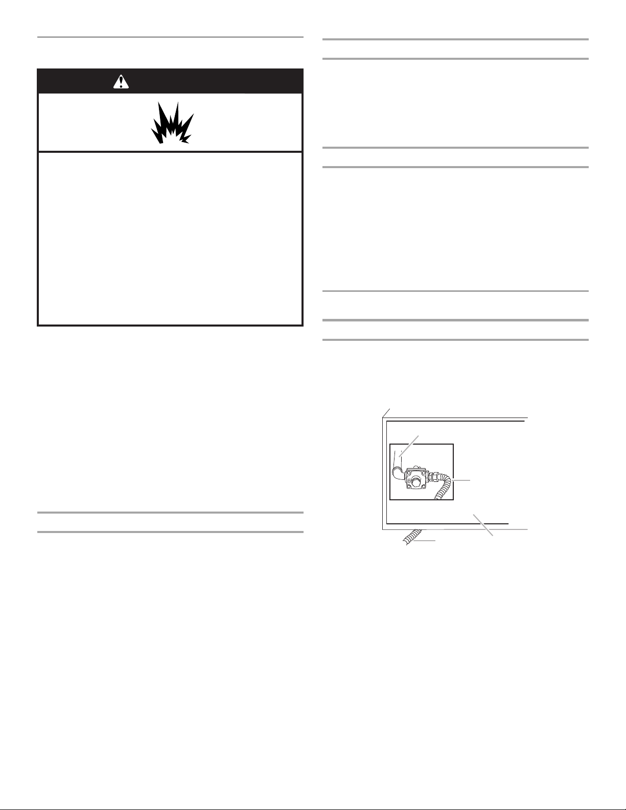
WARNING
Explosion Hazard
Do not store fuel tank in a garage or indoors.
Do not store grill with fuel tank in a garage or indoors.
Failure to follow these instructions can result in death,
explosion, or fire.
WARNING
Fire Hazard
Do not use grill near combustible materials.
Do not store combustible materials near grill.
Doing so can result in death or fire.
Select a location that provides minimum exposure to wind and
traffic paths. The location should be away from strong draft
areas.
Do not obstruct flow of combustion and ventilation air.
Clearance to combustible construction for built-in and
freestanding outdoor grills:
■ A minimum of 24" (58.0 cm) must be maintained between the
front of the grill hood, sides and back of the grill and any
combustible construction.
■ A zero clearance may be maintained on the insulated jacket
surface to combustible construction.
Rotisserie
A 6" (15.2 cm) minimum clearance is needed for the rotisserie
motor.
A grounded, 3-prong outlet located to the left of the grill is
required. See “Electrical Requirements” section.
5
Page 6
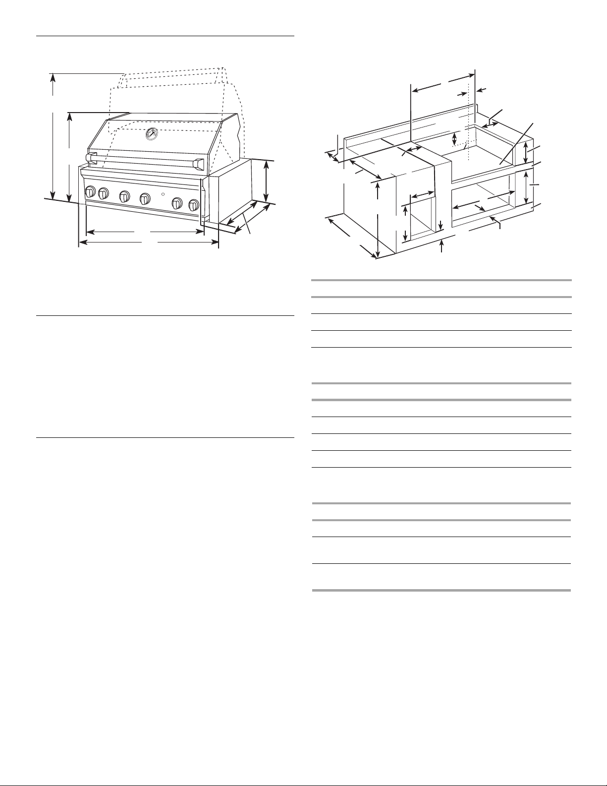
Product Dimensions
38"
(96.5 cm)
25⁵⁄₈"
(65.0 cm)
11¾"
(29.8 cm)
27¾"
A
B
A. 27" (68.6 cm)
36" (91.4 cm)
48" (121.9 cm)
B. 27" (68.6 cm) models - 32
36" (91.4 cm) models - 41
48" (121.9 cm) models - 53
⁷⁄₈
" (83.3 cm)
⁷⁄₈
" (106.2 cm)
⁷⁄₈
" (136.6 cm)
(70.5 cm)
23⁷⁄₈"
(60.5 cm)
Built-In Outdoor Grill Enclosure
This built-in outdoor grill is only for installation in a built-in
enclosure constructed of combustible and non-combustible
materials. Some types of non-combustible materials could be
brick, firewall or steel. Some types of combustible materials
could be wood or laminate.
The enclosure for the built-in outdoor grill is to be a minimum
of 11¾" [29.8 cm] high x 24" [61.0 cm] deep x (33" [83.8 cm] for
27" [68.6 cm] grill and 42" [106.7 cm] for 36" [91.4 cm] grill and
54" [137.2 cm] for 48" [121.9 cm] grill) wide.
Cabinet Cutout Dimensions
Enclosure and clearance dimensions that are shown must be
used. Given dimensions provide required clearances.
The installation of this grill must conform with local codes or, in
the absence of local codes, with either the National Fuel Gas
Code, ANSI Z223.1/NPFA 54, Natural Gas and Propane
Installation Code, CSA B149.1, or Propane Storage and Handling
Code, B149.2.
Copies of the standards listed may be obtained from:
CSA International
8501 East Pleasant Valley Rd.
Cleveland, Ohio 44131-5575
NOTE: The grill drops into the opening and the bottom of the grill
should be supported by the bottom support of the cabinet
cutout.
A
3" (7.6 cm)
min to
open hood
24"
(61.0 cm)
36½"
(92.7 cm)
27" (68.6 cm) min
12" (30.5 cm)
min to any
accessory
20 ⁷⁄ ₈"
(53.0 cm)
2¼"
(5.7 cm)
7 ³⁄₈"
(18.7 cm)
C
2½" (6.4 cm)
location at
rear of grill
1¹⁄₂" (2.9 cm) min around
optional doors or drawers
12" (30.5 cm)
min to any
accessory
Gas line
B
opening for mounting
Bottom
support
11 ¾"
(29.6 cm)
1¹⁄₂"
(3.8 cm)
20 ⁵⁄₈"
(52.5 cm)
2 ⁵⁄₈"
(6.8 cm)
A
Grill Size Cutout Width
27" (68.6 cm) 33" (83.8 cm)
36" (91.4 cm) 42" (106.7 cm)
48" (121.9 cm) 54" (137.2 cm)
B
Optional Access Doors* Cutout Width
27" (68.6 cm) 25¹⁄₈" (64.1 cm)
30" (76.2 cm) 28¹⁄₈" (71.1 cm)
36" (91.4 cm) 34¹⁄₈" (87.0 cm)
48" (121.9 cm) 46¹⁄₈" (117.4 cm)
C
Optional Drawers* Width Depth
14" (35.6 cm)
12¼" (31.8 cm) 23⁵⁄₈" (60.0 cm)
Utility Drawers
14" (35.6 cm)
12¼" (31.8 cm) 23⁵⁄₈" (60.0 cm)
Trash Drawers
*See “Assistance or Service” section to order.
6
Page 7
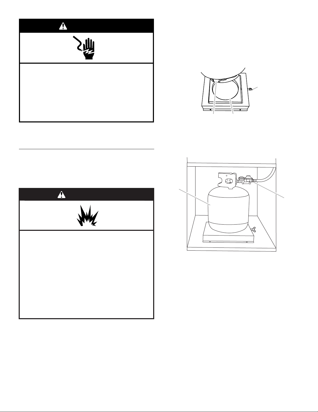
Built-in Outdoor Grill Enclosure Ventilation for LP Gas:
An enclosure for an LP gas fuel tank is to be ventilated by
openings at both the top and lower levels of the enclosure.
If converting to LP gas these vents are to be in the enclosure:
An enclosure for use with an LP gas fuel tank for built-in
installation is to have at least one ventilation opening on an
exposed exterior side located within 5" (12.7 cm) of the top is to
be a minimum of 20 in.
within 1" (2.5 cm) of the bottom of the enclosure and the bottom
opening is to be a minimum of 10 in.
openings are to be unobstructed. Every opening is to be a
minimum of ¹⁄₈" (0.32 cm) wide.
2
20 in.
(129.0 cm2) min.
ventilation both sides
2
(129.0 cm2). One ventilation opening
2
(64.5 cm2). All vent
A 120-volt, 60-Hz, AC-only, 15-amp, fused electrical supply is
required.
It is recommended that a separate circuit servicing only this grill
be provided.
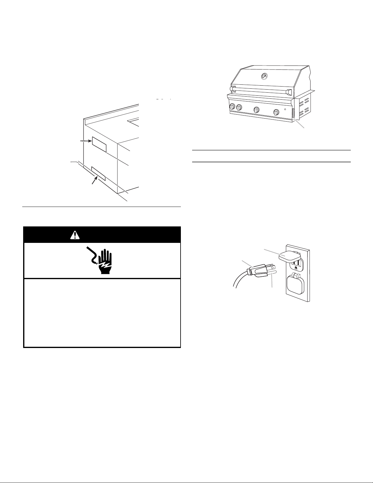
The model/serial number rating plate is located on the right-hand
side of the grill. See the following illustration.
A
A. Model/serial number plate
1" (2.5 cm) max.
10 in.2 (64.5 cm2) min.
ventilation both sides
5" (12.7 cm) max.
5" (12.7 cm) max.
Electrical Requirements
WARNING
Electrical Shock Hazard
Plug into a grounded 3 prong outlet.
Do not remove ground prong.
Do not use an adapter.
Do not use an extension cord.
Failure to follow these instructions can result in death,
fire, or electrical shock.
Recommended Ground Method
The outdoor grill, when installed, must be electrically grounded in
accordance with local codes or, in the absence of local codes,
with the National Electrical Code ANSI/NFPA 70, or Canadian
Electrical Code, CSA C22.1.
Copies of the standards listed above may be obtained from:
CSA International
8501 East Pleasant Valley Rd.
Cleveland, Ohio 44131-5575
National Fire Protection Association
One Batterymarch Park
Quincy, Massachusetts 02269
B
A
C
A. 3-prong ground plug
B. 3-prong polarized type outdoor outlet
C. Ground prong
If codes permit and a separate ground wire is used, it is
recommended that a qualified electrician determine that the
ground path is adequate.
Check with a qualified electrician if you are not sure whether the
grill is properly grounded.
7
Page 8
Gas Supply Requirements
WARNING
Burner Requirements for High Altitude
Input ratings shown on the model/serial rating plate are for
elevations up to 2,000 ft (609.6 m).
For elevations above 2,000 ft (609.6 m), ratings are reduced at a
rate of 4% for each 1,000 ft (304.8 m) above sea level. Orifice
conversion is required for elevations above 2,000 ft (609.6 m).
See “Assistance or Service” section to order High Altitude
Conversion Kit.
Explosion Hazard
Use a new CSA International approved “outdoor”
gas supply line.
Securely tighten all gas connections.
If connected to LP, have a qualified person make sure
gas pressure does not exceed 11” (28 cm) water
column.
Examples of a qualified person include:
licensed heating personnel,
authorized gas company personnel, and
authorized service personnel.
Failure to do so can result in death, explosion, or fire.
Observe all governing codes and ordinances.
IMPORTANT: The installation of this grill must conform with local
codes or, in the absence of local codes, with either the National
Fuel Gas Code, ANSI Z223.1/NPFA 54, Natural Gas and Propane
Installation Code, CSA B149.1, or Propane Storage and Handling
Code, B149.2.
IMPORTANT: Grill must be connected to a regulated gas supply.
Refer to the model/serial rating plate for information on the type
of gas that can be used. If this information does not agree with
the type of gas available, check with your local gas supplier.
Gas Conversion:
No attempt shall be made to convert the grill from the gas
specified on the model/serial rating plate for use with a different
gas type without consulting the serving gas supplier. The
conversion kits specified by the manufacturer must be used.
Gas Supply Line Pressure Testing
Testing above ½ psi (3.5 kPa) or 14" (35.5 cm) WCP (gauge):
The grill and its individual shutoff valve must be disconnected
from the gas supply piping system during any pressure testing of
that system at test pressures greater than ½ psig (3.5 kPa).
Testing below ½ psi (3.5 kPa) or 14" (35.5 cm) WCP (gauge) or
lower:
The grill must be isolated from the gas supply piping system by
closing its individual manual shutoff valve during any pressure
testing of the gas supply piping system at test pressures equal to
or less than ½ psig (3.5 kPa).
Gas Connection Requirements
Natural Gas
Built-in grill models are equipped for use with Natural gas. They
are design-certified by CSA International for LP (propane) gases
with appropriate conversion.
Built-in models are set for Natural gas use and have a pressure
regulator with ½" female pipe threads.
A
B
Gas Pressure Regulator
The gas pressure regulator supplied with this grill must be used.
The inlet (supply) pressure to the regulator should be as follows
for proper operation:
LP Gas:
Set pressure: 11" (27.9 cm) WCP
Inlet (supply) pressure: 11" to 14" (27.9 cm to 35.5 cm) WCP
Natural Gas:
Set pressure: 4" (10.2 cm) WCP
Inlet (supply) pressure: 7" to 14" (17.8 cm to 35.5 cm) WCP
maximum.
Contact local gas supplier if you are not sure about the inlet
(supply) pressure.
8
D
A. Grill gas pipe
B. New CSA International approved
“outdoor” flexible gas supply line
C. Rear of grill
D. To Natural gas supply
The supply line shall be equipped with an approved shutoff valve.
This valve should be located in the same area as the grill and
should be in a location that allows ease of opening and closing.
C
Page 9
Do not block access to the shutoff valve. The valve is for turning
B
A
on or shutting off gas to the grill.
B
A
To convert to LP gas, the LP Gas Conversion Kit Part Number
W10118099 must be used. Follow instructions included with kit.
A
C
A. Gas supply line
B. Shutoff valve “open” position
C. To grill
LP Gas Conversion Using a Local LP Gas Supply
Conversion must be made by a qualified person. The installation
of this grill must conform with local codes or, in the absence of
local codes, with either the National Fuel Gas Code, ANSI
Z223.1/NPFA 54, Natural Gas and Propane Installation Code,
CSA B149.1, or Propane Storage and Handling Code, B149.2.
INSTALLATION INSTRUCTIONS
Unpack Grill
WARNING
B
D
A. Grill gas pipe
B. New CSA International approved
“outdoor” flexible gas supply line
C. Rear of grill
D. To local LP gas supply
C
LP Gas Conversion Using a 20 lb LP Gas Fuel Tank
To convert to LP gas, the LP Gas Conversion Kit Part Number
W10118099 must be used. Follow instructions included with kit.
A 20 lb LP gas fuel tank must be purchased separately.
3. Remove foam block and wrap from inside the grill.
Excessive Weight Hazard
Use two or more people to move and install grill.
Failure to do so can result in back or other injury.
■ Unpack grill. Remove all packaging materials and remove grill
from carton.
■ Move grill close to desired outdoor location.
■ Open the hood.
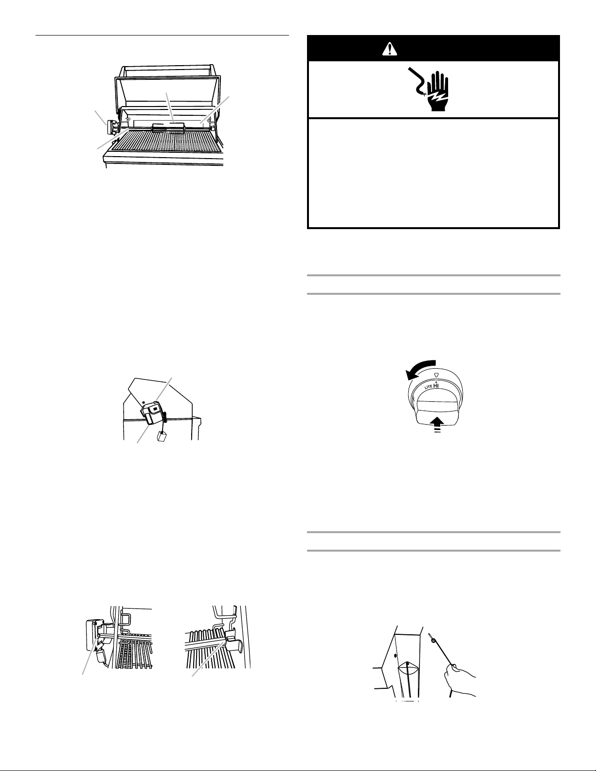
Remove Packaging Material Inside the Grill
1. Cut the tiedowns holding the grates together.
2. Remove rotisserie skewer (on some models), warming shelf
and grill grates from inside the grill and remove packaging
material.
A
A. Foam block
B. Foam wrap
4. Replace the grill grates.
5. Place warming shelf on brackets as shown.
B
A
A. Warming shelf brackets
B. Warming shelf
9
Page 10
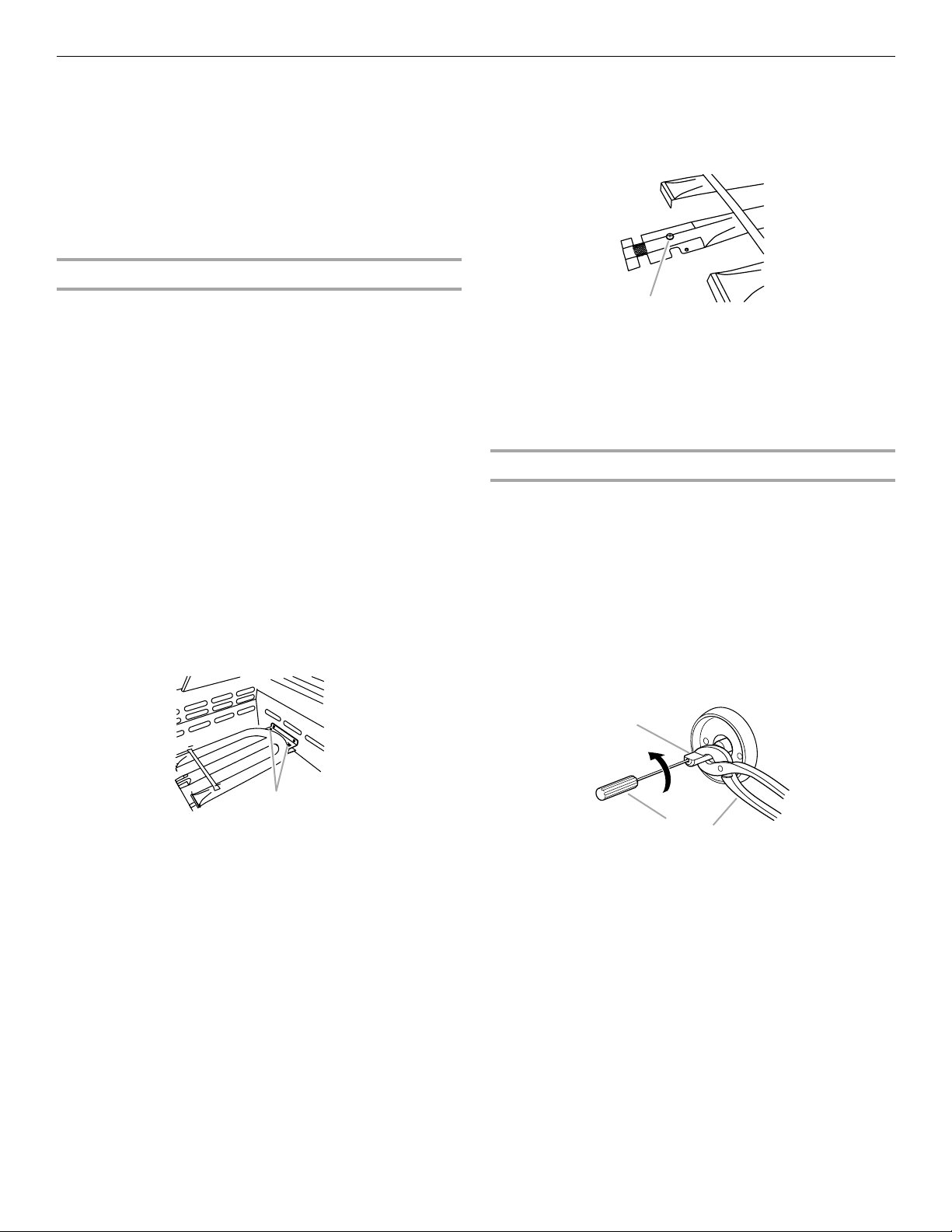
6. On some models, install rotisserie mounting bracket using
2 screws.
A B
A. 2 screws
B. Rotisserie bracket
7. Dispose of/recycle all packaging material.
■ If local codes permit, use an outdoor flexible stainless
steel tubing gas connector, design-certified by CSA
International, to connect the grill to the rigid gas supply
line. A ⁵⁄₈" diameter line is recommended. Using a wrench
to tighten, connect the gas supply to the grill. Use pipejoint compound on all non-flared male threads. Do not
kink or damage the flexible connector when moving the
grill.
■ Pipe-joint compounds suitable for use with Natural gas
must be used. Do not use Teflon® tape.
A
Make Gas Connection
NOTE: If grill has been converted to LP gas, follow instructions in
“Conversion to LP Gas” at the end of this section.
WARNING
Fire Hazard
Do not use grill near combustible materials.
Do not store combustible materials near grill.
Doing so can result in death or fire.
Natural Gas Use
The installation of this grill must conform with local codes or, in
the absence of local codes, with either the National Fuel Gas
Code, ANSI Z223.1/NPFA 54, Natural Gas and Propane
Installation Code, CSA B149.1, or Propane Storage and Handling
Code, B149.2.
1. Place grill into outdoor enclosure, but leave enough room in
back to connect to gas supply and electrical plug-in.
WARNING
B
D
A. Grill gas pipe
B. New CSA International approved
“outdoor” flexible gas supply line
C. Rear of grill
D. To Natural gas supply
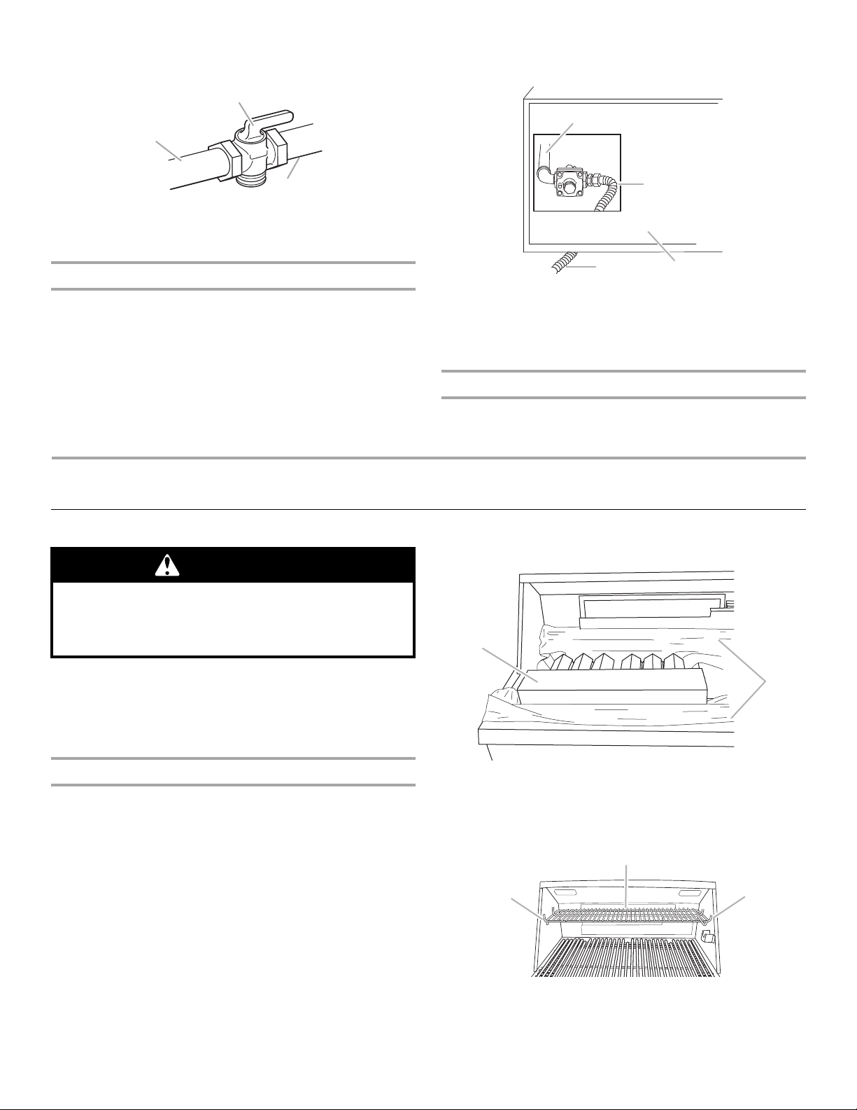
3. Open the manual shutoff valve in the gas supply line. The
valve is open when the handle is parallel to the gas pipe.
A
A. Closed valve
B. Open valve
4. Test all connections by brushing on an approved
noncorrosive leak-detection solution. Bubbles will show a
leak. Correct any leak found.
C
B
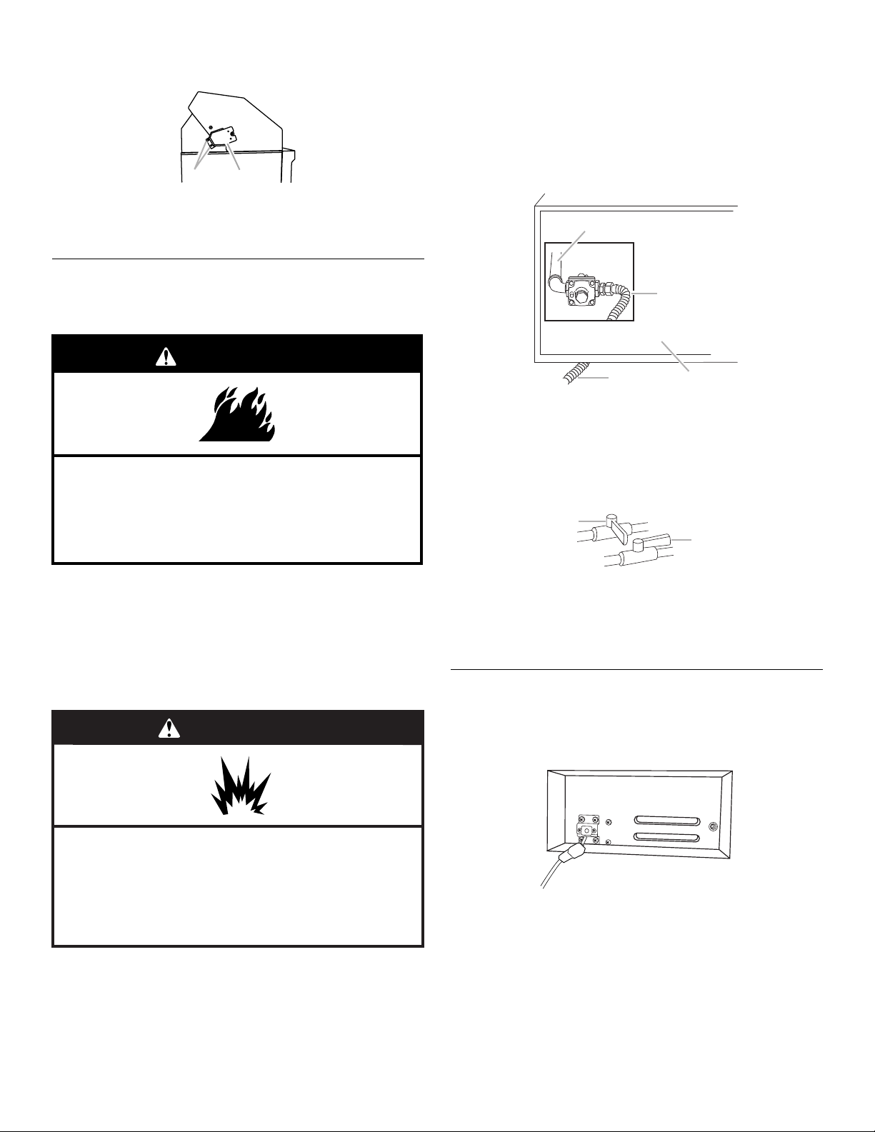
Plug in Grill
1. This built-in outdoor grill comes with a 5,000 mAmp power
transformer plug assembly for the grill lights and igniter. Plug
in the single-prong plug in the receptacle on the left
underside of the grill.
Explosion Hazard
Use a new CSA International approved “outdoor”
gas supply line.
Securely tighten all gas connections.
Failure to do so can result in death, explosion, or fire.
2. Make gas connections.
A combination of pipe fittings must be used to connect the
grill to the existing gas line.
10
A. Single-prong plug
Page 11
WARNING
C
B
Electrical Shock Hazard
Plug into a grounded 3 prong outlet.
Do not remove ground prong.
Do not use an adapter.
Do not use an extension cord.
Failure to follow these instructions can result in death,
fire, or electrical shock.
2. Plug into a grounded 3-prong outlet.
3. Gently slide grill completely into outdoor enclosure.
4. Now go to the “Check and Adjust the Burners” section.
Conversion to LP Gas
(If LP gas conversion is desired)
IMPORTANT: If LP gas conversion is desired, follow
requirements outlined in the “Gas Connection Requirements”
section.
WARNING
To Install the 20 lb LP Gas Fuel Tank:
1. Install the 20 lb LP gas fuel tank tray according to the
instructions provided with the LP Gas Conversion Kit, Part
Number W10118099.
2. Place the 20 lb LP gas fuel tank bottom collar into the
mounting hole in the LP tank tray.
3. Tighten the locking screw against the bottom collar of the
20 lb LP gas fuel tank to secure.
A
4. Screw the gas pressure regulator/hose assembly to the 20 lb
LP gas fuel tank as shown.
A
B
A. Bottom collar
B. Mounting hole
C.Locking screw
Explosion Hazard
Use a new CSA International approved “outdoor”
gas supply line.
Securely tighten all gas connections.
If connected to LP, have a qualified person make sure
gas pressure does not exceed 11” (28 cm) water
column.
Examples of a qualified person include:
licensed heating personnel,
authorized gas company personnel, and
authorized service personnel.
Failure to do so can result in death, explosion, or fire.
IMPORTANT: A 20 lb LP gas fuel tank must be purchased
separately.
IMPORTANT: The gas pressure regulator/hose assembly
supplied with the conversion kit must be used. Replacement gas
pressure regulator/hose assembly specific to your model, is
available from your outdoor grill dealer.
A. 20 lb LP gas fuel tank
B. Gas pressure regulator/hose assembly
5. Turn on the gas supply. Wait a few minutes for gas to move
through the gas line.
6. Test all connections by brushing on an approved
noncorrosive leak-detection solution. Bubbles will show a
leak. Correct any leak found.
7. Go to “Check and Adjust the Burners” section.
11
Page 12
Check and Adjust the Burners
The burners are tested and factory-set for most efficient
operation. However, variations in gas supply and other conditions
may make minor adjustments to air shutter or low flame setting
necessary.
It is recommended that a qualified person make burner
adjustments.
NOTE: The rotisserie burner cannot be adjusted.
Checking and adjusting the grill burner flames requires removing
the grate and sear plates.
Burner Flame Characteristics
The flames of the grill burners and side burners (on some models)
should be blue and stable with no excessive noise or lifting (LP
gas flames will have a slightly yellow tip). A yellow flame indicates
not enough air. If flame is noisy or lifts away from the burner, there
is too much air. Some yellow tips on flames when the burner is
set to HI setting are acceptable as long as no carbon or soot
deposits appear.
Check that burners are not blocked by dirt, debris, insect nests,
etc. and clean as necessary. If they are clean, adjust air shutters
as needed.
IMPORTANT: Before adjusting air shutters, let burners cool
completely.
To Adjust:
1. Light grill using information in the “Outdoor Grill Use” section.
2. Observe flame to determine which burners need adjustment
and how the flame is acting.
3. Turn off the valve and wait until grill and burners cool
completely.
4. Remove grill grates and sear plates.
5. Remove the 2 screws that hold the burner in place. Remove
gas burner from the grill.
6. If flame is yellow (not enough air), turn air shutter adjustment
screw counterclockwise.
If flame is noisy or lifts away from burner (too much air), turn
air shutter adjustment screw clockwise.
A
A. Air shutter adjustment screw
Adjustment should be made clockwise or counterclockwise
from ¹⁄₈" (3.2 mm) to ¹⁄₄" (6.4 mm).
7. Replace gas burner, sear plates and grates.
8. Light grill using information in the “Outdoor Grill Use” section.
See “Burner Flame Characteristics.”
Low Flame Adjustment
If flame goes out on the “LO” setting, the low flame setting must
be adjusted.
1. Turn off the valve and wait until grill and burners are cool.
2. Remove grill grates and sear plates.
3. Light grill using information in the “Outdoor Grill Use” section.
4. Turn burner to its lowest setting and remove knob.
5. Hold valve stem with pliers and insert a small flat-blade
screwdriver into the shaft.
6. Watch the flame and slowly turn the screwdriver
counterclockwise.
7. Adjust flame to minimum stable flame.
A. 2 screws
A
A
B
C
A. Valve stem
B. Small flat-blade screwdriver
C. Pliers
8. Replace the control knob and turn off the burner.
9. Repeat steps 3 through 8 for each burner if needed.
10. Replace the sear plates and grates after the burners have
cooled.
12
Page 13
OUTDOOR GRILL USE
This manual covers several different models. The grill you have purchased may have some or all of the features listed. The locations and
appearances of the features shown here may not match those of your model.
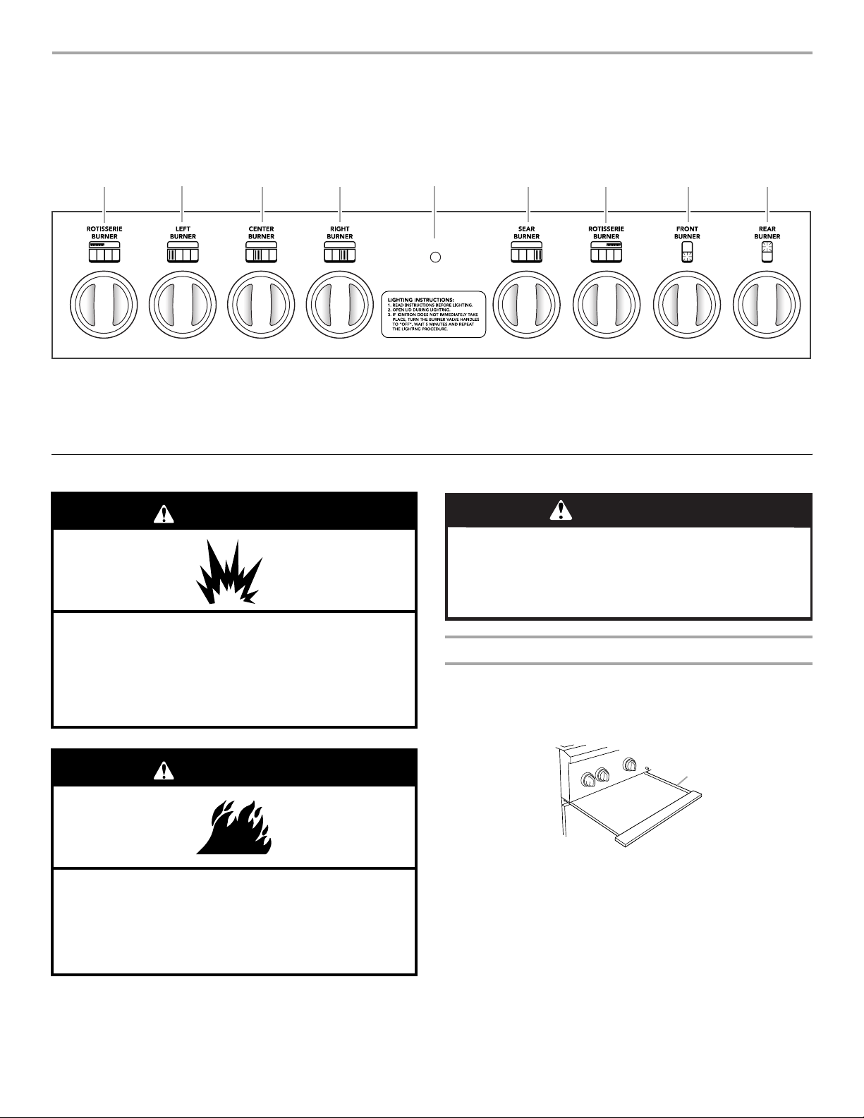
Control Panel
A
B
A. Left rotisserie burner control knob
B. Left grill burner control knob
C. Center grill burner control knob
D. Right grill burner control knob
E. Hood lights switch
C D
E
LIGHTS
F
F. S e ar b urn er co nt r ol kn o b
G. Right rotisserie burner control knob
H. Front side burner control knob
I. Rear side burner control knob
G
H I
Using Your Outdoor Grill
WARNING
Do not let food sit for more than one hour before or
after cooking.
Doing so can result in food poisoning or sickness.
WARNING
Food Poisoning Hazard
Explosion Hazard
Do not store fuel tank in a garage or indoors.
Do not store grill with fuel tank in a garage or indoors.
Failure to follow these instructions can result in death,
explosion, or fire.
WARNING
Fire Hazard
Do not use grill near combustible materials.
Do not store combustible materials near grill.
Doing so can result in death or fire.
Prepare the Gas Supply
1. Open the hood completely. Do not light burners with the hood
closed.
2. Make sure control knobs are turned to OFF. The drip pan
must be in place and pushed all the way to the back.
A
A. Drip pan
13
Page 14
Turn the Gas Supply On
1. For outdoor grills using gas supply source other than 20 lb LP
gas fuel tank:
Open the manual shutoff valve in the gas supply line. The
valve is open when the handle is parallel to the gas pipe.
A
B
A. Closed valve
B. Open valve
2. For outdoor grills using a 20 lb LP gas fuel tank:
Slowly open the tank valve.
NOTE: If flow limiting device activates, your grill may not
light. If your grill does light, the flames will be low and will not
heat properly. Turn tank valve and all control knobs off and
wait 30 seconds. After shutting off the tank, very slowly open
tank valve and wait 5 seconds before lighting.
Lighting the Grill and Infrared Sear Burner
IMPORTANT: If burner does not light immediately, turn the
burner knob to OFF and wait 5 minutes before relighting.
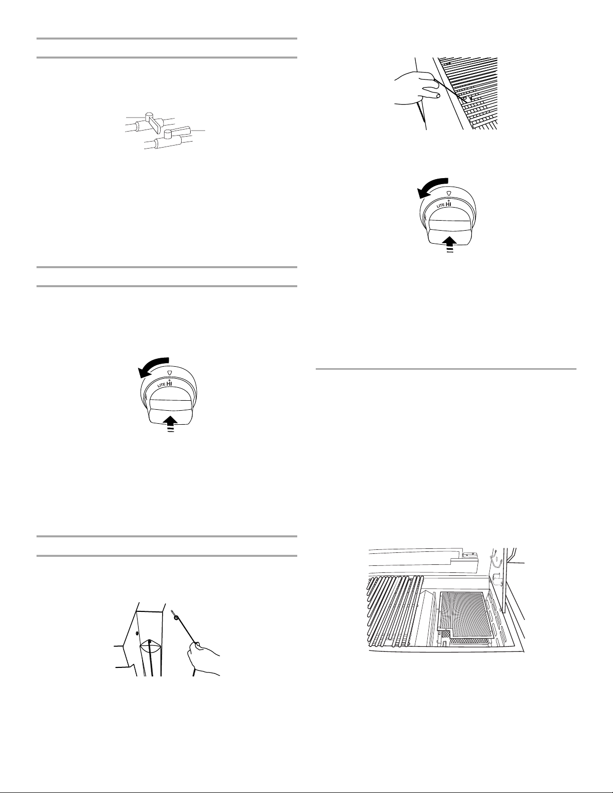
1. Do not lean over the grill.
2. Select the burner you want to light. Push in and turn the grill
burner control knob to LITE/HI, while continuing to hold it in.
4. Guide the lit match between the grill grate and one of the
slots in the sear plate.
5. Push in and turn the burner knob to LITE/HI for the burner
closest to the lit match. The burner will light immediately.
When burner is lit, turn knob to desired setting.
6. Repeat steps 2 through 5 for each main burner.
7. Remove match and replace manual lighting extension inside
the cabinet drawer.
IMPORTANT:
If burner does not light immediately, turn the burner knob to OFF
and wait 5 minutes before relighting.
If any burners do not light after attempting to light them manually,
contact the KitchenAid Customer eXperience Center. See the
“Assistance or Service” section.
3. Surface Ignition Type Burners:
You will see the igniter glow. When burner is lit, release the
knob. Turn knob to desired setting.
Spark Ignition Type Burners:
You will hear the “snapping” sound of the spark. When burner
is lit, release the knob. Turn knob to desired setting.
4. Repeat for each of the other burners as needed.
Manually Lighting Main Grill and Infrared Sear Burners
1. Do not lean over the grill.
2. Remove the manual lighting extension (see following
illustration) and attach a match to the split ring.
Right-hand side flange
Using Your Infrared Sear Burner
Infrared grilling produces intense heat which quickly sears the
meat. Searing locks in flavor and juices while allowing the outer
surface to absorb smoke and food aroma that is produced as
grease and drippings are vaporized by the burner. The result is a
crisp, flavorful outside with a tender, juicy inside.
■ Preheat the infrared sear burner for 5 minutes.
■ Ensure that meats are fully thawed and that all excess fat is
trimmed away prior to grilling.
■ Leave the burner set to HI when placing food on the grill to
sear.
■ Use the sear burner to sear meat 1 to 2 minutes on each side,
then move the meat to the main grill cooking surface to finish
grilling to the desired doneness.
NOTE: View is shown with grates removed. Grates are
to be in place when using the infrared sear burner.
3. Strike the match to light it.
14
Page 15
Using Your Rotisserie
D
C
A
B
A. Rotisserie motor
B. Spit rod
C. Rotisserie fork
D. Rotisserie burner
For best cooking results, do not use main grill burners when
using the rotisserie.
The rotisserie system is designed to cook food from the rear
using intense, searing infrared heat.
NOTE: To avoid product damage when not using the rotisserie,
remove motor and store indoors. Remove spit rod and forks.
Store out of reach of children.
WARNING
Electrical Shock Hazard
Plug into a grounded 3 prong outlet.
Do not remove ground prong.
Do not use an adapter.
Do not use an extension cord.
Failure to follow these instructions can result in death,
fire, or electrical shock.
8. Plug into a grounded 3 prong outlet.
9. Turn on the rotisserie motor and light the rotisserie burner.
See the following “Lighting the Rotisserie Burner” section.
Lighting the Rotisserie Burner
To Use:
1. Remove warming shelf.
2. Mount rotisserie motor on the rotisserie’s mounting bracket.
Position it securely into support bracket slots. Plug in the
single-prong plug of the 500 mAmp transformer assembly
into rotisserie motor.
B
A
A. Rotisserie motor
B. 500 mAmp single-prong power cord
3. To load the spit rod, slide one of the rotisserie forks onto the
spit rod with prongs facing inward.
4. Push spit rod through the center of the food, then slide
second rotisserie fork into position.
5. Center the food and rotisserie forks on spit rod and tighten
wing nuts on the rotisserie forks. If necessary, secure loose
food portions with butcher’s string.
6. Once the food is positioned on spit rod, place pointed end of
rod through the hole in the left side of the grill and into the
rotisserie motor, then lower the notched end of the spit rod
onto the support bracket on the opposite side.
IMPORTANT: If the rotisserie burner does not light immediately,
turn the rotisserie burner knob to OFF and wait 5 minutes before
relighting.
1. Do not lean over the grill.
2. Push in and turn the control knob to LITE/HI.
Surface Ignition Type Burners:
You will see the igniter glow.
Spark Ignition Type Burners:
Your will hear the “snapping” sound of the spark.
3. When the rotisserie burner lights, continue to hold the knob in
for another 10 seconds, then release the knob and burner will
stay lit.
Manually Lighting the Rotisserie Burner
IMPORTANT: If the rotisserie burner does not light immediately,
turn the rotisserie burner knob to OFF and wait 5 minutes before
relighting.
1. Do not lean over the grill.
2. Remove the manual lighting extension (see following
illustration) and attach a match to the split ring.
A
A. Pointed end of spit rod
B. Notched end of spit rod
7. Check that food is centered with the rotisserie burner. If not,
loosen wing nuts, reposition food and retighten wing nuts.
B
Right-hand side flange
3. Strike the match to light it.
15
Page 16

4. Gently hold the lit match close to the rotisserie burner.
B
A
A. Lighting extension
B. Rotisserie burner
5. Push in and turn the control knob to LITE/HI. Hold this knob
in for 10 seconds after the burner is lit.
Surface Ignition Type Burners:
You will see the igniter glow until after the knob is released.
Spark Ignition Type Burners:
You will hear the “snapping” sound of the spark until after the
knob is released.
6. Remove the match and replace the manual lighting extension
inside the cabinet drawer.
Trussing Poultry for the Rotisserie
1. Load the spit rod by sliding one of the forks on the rod, with
the prongs facing inward. Tighten the screw to keep it from
slipping.
2. Push the rod through the center of the bird.
3. Cut 24" (61 cm) of butcher’s string and center it under the
bird, breast side up.
4. Wrap each end of the string around the wings; catch each
wing tip. Bring the string tightly together at the top of the
breast and knot. It is not necessary to cut off the extra string.
5. Cut another 20" (50.8 cm) of string and lay it under the back
of the bird. Wrap it around the tail then around the spit rod,
cinching tightly.
6. Cross the legs on top of spit rod; tie string around the
crossed legs.
7. Connect the twine holding the legs, to the string holding the
wings, and knot. Cut off any bits of hanging string.
8. Slide on the second fork pushing the tines into the
drumsticks.
9. Center the food and forks on the rod and tighten the thumb-
screws. The bird should be firmly in place on the rotisserie
spit rod.
ROTISSERIE CHART
Use a portable meat thermometer to check internal doneness of
the food.
Turn off rotisserie burner when meat thermometer reads 5°F/3°C
lower than desired internal temperature. Continue rotating, hood
closed, for 10 minutes before carving.
Timing is affected by weather conditions such as wind and
outside temperature.
Rotisserie Cooking Tips
WARNING
Food Poisoning Hazard
Do not let food sit for more than one hour before or
after cooking.
Doing so can result in food poisoning or sickness.
Rotisserie cooking rotates food in front of the rotisserie burner,
creating an intense heat for searing the outside and sealing in
natural juices.
The rotisserie burner reaches cooking temperatures in about
1 minute. It is not necessary to preheat when using the rotisserie.
■ Select tender meat and poultry.
■ Allow at least 1" (2.5 cm) space between rotisserie burner
and the food.
■ To make cleanup easier, place a pan under the food to catch
drippings.
■ The hood can be opened or closed, but when using the
rotisserie with the smoker the hood should be closed.
■ Add barbecue sauce or glaze only during the last 10 minutes
of cooking to keep sauce from burning.
Food Weight Internal
Beef
Roasts
Rib Eye
Sirloin Tip
Rib, boneless
Poultry
Chicken
Turkey, whole
Lamb
Boneless leg 4-7 lbs
Pork
Loin roast,
boneless
4-6 lbs
1.5-2.2 kg
3-6 lbs
1.1-2.2 kg
7-10 lbs
2.6-3.7 kg
1.5-2.6 kg
4-6 lbs
1.5-2.2 kg
Doneness or
Temperature
(°F/°C)
Medium-rare
(145°F/ 63°C)
Medium
(160°F/71°C)
Breast
(170°F/ 77°C)
Thigh
(180°F/82°C)
Breast
(170°F/77°C)
Thigh
(180°F/82°C)
Medium
(160°F/71°C)
Medium
(160°F/71°C)
Approximate
Grilling Time
(min/lb)
15-20
20-25
25-30
25-30
11-20
11-20
20-25
20-23
16
Page 17

Using Your Smoker Box
(on some models and as an accessory)*
The smoker box can be used when grilling or when using your
rotisserie.
1. Prepare wood chips/pellets following manufacturer’s
directions.
2. Open smoker box lid and add prepared chips/pellets onto the
grate inside the smoker box.
NOTE: For about 1 hour of smoking, fill the smoker box
approximately one-fourth full of chips/pellets.
3. Remove the small grate from the grill and replace with the
smoker box.
TIPS FOR OUTDOOR
GRILLING
WARNING
Food Poisoning Hazard
Do not let food sit for more than one hour before or
after cooking.
Doing so can result in food poisoning or sickness.
A
A. Shown with small grate removed
B. Smoker box
4. Light the burner below the smoker box and preheat on high
until smoker begins smoking. Reduce the heat setting to
keep the smoke at the amount desired.
B
To Refill the Smoker Box During Use
IMPORTANT: You may want to wear oven mitts when opening
and closing the smoker box lid.
1. Open grill hood.
2. Lift smoker box lid and add more prepared chips/pellets.
3. Close the smoker box lid.
4. Close the grill hood and continue grilling.
*See “Assistance or Service” section to order.
Hood Lights
The 5,000 mAmp power transformer must be plugged in for the
hood lights to work. See “Plug in Grill” in the “Installation
Instructions” section.
To U s e:
Press the LIGHTS button on the control panel to turn the hood
lights on and off.
Before Grilling
■ Thaw food items before grilling.
■ Preheat grill on high (use all grill burners) 10 minutes. The
hood must be closed during preheating. There is no need to
use the back rotisserie burner for preheating. Preheating
provides the high heat needed to brown and seal the juices.
■ Shorten the preheat time when grilling high-fat cuts of meat
or poultry, such as chicken thighs. This will help reduce
flare-ups.
■ Lightly oil the grill grates or the food when cooking low-fat
cuts of meat, fish or poultry, such as lean hamburger patties,
shrimp or skinless chicken breasts.
■ Using too much oil can cause gray ash to deposit on food.
■ Trim excess fat from meats prior to cooking to reduce
flare-ups.
■ Make vertical cuts at 2" (5 cm) intervals around the fat edge
of meat to avoid curling.
■ Add seasoning or salt only after the cooking is finished.
During Grilling
■ Turn foods only once. Juices are lost when meat is turned
several times.
■ Turn meat just when juices begin to appear on the surface.
■ Avoid puncturing or cutting the meats to test doneness. This
allows juices to escape.
■ It may be necessary to lower the heat setting for foods that
cook a long time or are marinated or basted in a sugary
sauce.
■ If using a high flame, add barbecue sauce only during the last
10 minutes of cooking to avoid burning the sauce.
■ The degree of doneness is influenced by the type of meat, cut
of meat (size, shape and thickness), heat setting selected,
and length of time on the grill.
■ Cooking time will be longer with an open grill cover.
17
Page 18

Cooking Methods
For optimal use of the SureSear™ system, the following cooking
methods are recommended.
Direct Heat
Cooking by direct heat means the food is placed on grill grates
directly above lighted burners. Hood position can be up or down.
If hood is in the up position, total cooking times may be longer.
Direct heat sears the food. Searing is a process that seals natural
juices in food by cooking with intense heat for a short period of
time. While juices stay inside, the outside is browned with a
flavorful grilled coating.
Indirect Heat
For best results, do not select the indirect heat cooking method
when it is windy.
Grilling Chart
■ Knobs have High, Medium and Low settings for flame
adjustment.
■ Heat settings indicated are approximate.
■ Grilling times are affected by weather conditions.
Cooking by indirect heat means the food is placed on the grill
grate above an unheated burner, allowing heat from lighted
burner(s) on either side to cook the food.
If possible, turn on 2 burners. Cook with the hood down. This will
shorten the cooking time.
Indirect Cooking
Place food only on the grill grate over the OFF burners.
Grill Size Burner Burner Burner Burner
1234
27" (68.6 cm) ON OFF - 36" (91.4 cm) ON OFF ON 48" (121.9 cm) ON OFF ON OFF
■ When 2 temperatures are listed, for example: Medium to
Medium-Low, start with the first and adjust based on cooking
progress.
■ Cooking times may vary from chart times depending on the
type of fuel, Natural or LP gas.
FOOD COOKING METHOD/
Beef
Hamburgers ½" (1.3 cm) to
¾" (1.9 cm) thick
Roasts
Rib Eye, Sirloin
Steaks, 1" (2.5 cm)
Porterhouse, Rib, T-bone,
Top L oin, Sirl oin
Steaks, 1½" (3.8 cm)
Porterhouse, Rib, T-bone,
Top L oin, Sirl oin
Top Round or Shoulder/
Chuck (London Broil)
1½" (3.8 cm) thick
Flank, ½" (1.3 cm) thick
Pork
Chops,
1" (2.5 cm)
1½" (3.8 cm) thick
Ribs
2½-4 lbs (0.9-1.5 kg)
Roast, boneless tenderloin,
1 lb (0.37 kg)
Ham half,
8-10 lbs (3-3.7 kg)
BURNER SETTING
DIRECT
Medium
INDIRECT
Medium/OFF/Medium
DIRECT
Medium
DIRECT
Medium
DIRECT
Medium
DIRECT
Medium
DIRECT
Medium to Med-Low
INDIRECT
Med/OFF/Med
DIRECT
Medium
INDIRECT
Med/OFF/Med
INTERNAL TEMP. TIME
Medium (160°F/71°C)
Med-Rare (145°F/63°C)
to Medium (160°F/71°C)
Med-Rare (145°F/63°C)
to Medium (160°F/71°C)
Med-Rare (145°F/63°C)
to Medium (160°F/71°C)
Med-Rare (145°F/63°C)
to Medium (160°F/71°C)
Med-Rare (145°F/63°C)
Medium (160°F/71°C)
Medium (160°F/71°C)
Medium (160°F/71°C)
Reheat (140°F/60°C)
(total minutes)
10-15
32-40 per lb
(12-15 per kg)
11-16
18-25
22-29
11-16
12-22
30-40
40-60
18-22
2-2½ hours
SPECIAL INSTRUCTIONS
Grill, turning once.
Tent with foil first 45-60 minutes
of cooking time.
Rotate steaks ¼ turn to create
criss-cross grill marks.
Grill, turning occasionally.
During last few minutes brush
with barbecue sauce if desired.
When done, wrap in foil.
Turn during cooking to brown
on all sides.
Wrap entire ham in foil and put
on grill without pan or drip pan.
Ham steak precooked,
½" (1.3 cm) thick
Hot Dogs
18
DIRECT
Preheat Medium
Grill Medium
DIRECT
Medium
Reheat (145°F/63°C)
Reheat (145°F/63°C)
7-10
5-10
Slit skin if desired.
Page 19

FOOD COOKING METHOD/
Chicken
Breast, boneless
Pieces, 2-3 lbs (0.75-
1.1 kg)
Lamb
Chops and Steaks,
Loin, Rib, Sirloin,
1" (2.5 cm) thick
1½" (3.8 cm) thick
Fish and Seafood
BURNER SETTING
DIRECT
Medium
DIRECT
Med-Low to Medium
DIRECT
Medium
DIRECT
Medium
INTERNAL TEMP. TIME
170°F/77°C
Breast 170°F/77°C
Thigh 180°F/82°C
Med-rare (145°F/63°C)
to Medium (160°F/71°C)
Med-rare (145°F/63°C)
to Medium (160°F/71°C)
(total minutes)
15-22 For even cooking, pound breast
10-20
16-20
SPECIAL INSTRUCTIONS
to ¾" (2.0 cm) thick.
Start bone side down.
Fillets, Steaks, Chunks
Halibut, Salmon,
Swordfish, 8 oz (0.25 kg)
Whole, Catfish, Rainbow
Trout, 8-11 oz (0.25-
0.34 kg)
Shellfish, Scallops, Shrimp
Turkey
Whole breast (bone-in)
Half breast (bone-in)
Whole,
7-12 lbs (2.6-5.4 kg)
Fresh Vegetables
Corn on the cob
Eggplant
Onion,
½" (1.3 cm) thick
Potatoes,
Sweet, whole
Baking, whole
Peppers,
Roasted
Squash,
Summer, Zucchini
Garlic
Roasted
DIRECT
Medium
DIRECT
High
DIRECT
Medium
INDIRECT
HI/OFF/HI
INDIRECT
Medium/OFF/Medium
INDIRECT
HI/OFF/HI
DIRECT
Medium
DIRECT
Medium
DIRECT
Medium
DIRECT
Medium
DIRECT
High
DIRECT
High
DIRECT
Medium
DIRECT
Medium
170°F/77°C
170°F/77°C
Breast 170°F/77°C
Thigh 180°F/82°C
4-6 per
½" (1.3 cm)
thickness of fish
5-7 per side
4-8
14-18
25-30
11-16
20-25
7-10
8-20
40-70
45-90
15-22
7-10
20-25
Grill, turning once. Brush grill
with oil to keep fish from
sticking. Remove when inside is
opaque and flaky with skin
easily removed.
Tent with foil until last
30 minutes of cooking time.
Start skin side down.
Less than 11 lbs. (5.0 kg)
Soak in cold water 20 minutes.
Do not husk. Shake off excess
water.
Wash and cut into ½" (1.3 cm)
slices or lengthwise. Brush with
olive oil.
Grill, turning once. Brush with
olive oil. Put a skewer through
several slices to hold together.
Individually wrap in heavy-duty
foil. Grill, rotating occasionally.
Wash and place on grill whole.
Char skin all around. Cool in a
paper bag or plastic wrap to
loosen blackened skin. Peel
and remove seeds.
Wash and cut into ½" (1.3 cm)
slices or lengthwise. Brush with
olive oil.
Cut off top, drizzle with olive oil
and wrap in double layer of foil.
19
Page 20

OUTDOOR GRILL CARE
B
Changing the Light Bulb
1. Unplug grill or disconnect power.
2. To remove glass light cover, remove screw and gently pry
downward with a small flat-blade screwdriver at the left side
of the cover, and pull away from the retainers.
A
B
A. Screw
B. Retainers
3. Remove bulb from socket.
4. Replace bulb with a new 12-volt, 25-watt maximum, halogen
bulb, using a tissue or wearing cotton gloves to handle the
bulb. To avoid damaging the bulb, do not touch the bulb with
bare fingers.
5. Replace glass light cover by placing sides of the lens into the
bulb retainers in the light housing and tightening the screw.
6. Plug in grill or reconnect power.
General Cleaning
IMPORTANT: Before cleaning, make sure all controls are off and
the grill is cool. Always follow label instructions on cleaning
products.
For routine cleaning, wash with soap and water using a soft cloth
or sponge. Rinse with clean water and dry at once with a soft,
lint-free cloth to avoid spots and streaks.
Do not use steel wool to clean the grill, as it will scratch the
surface.
Use vinyl grill cover, available from your local dealer, to shelter
finish from weather. See “Assistance or Service” section.
STAINLESS STEEL
IMPORTANT: To avoid damage to stainless steel surfaces, do not
use soap-filled scouring pads, abrasive cleaners, Cooktop
Polishing Creme, steel wool, gritty wash cloths or paper towels.
Cleaners should not contain chlorine. Damage may occur.
Food spills should be cleaned as soon as entire grill is cool. Spills
may cause permanent discoloration.
Cleaning Method:
■ Rub in direction of grain to avoid scratching or damaging the
surface.
■ KitchenAid
4396920 (not included):
See “Assistance or Service” section to order.
■ Liquid detergent or all-purpose cleaner:
Rinse with clean water and dry with soft, lint-free cloth.
■ Vinegar to remove hard water spots.
■ Glass cleaner to remove fingerprints.
®
Stainless Steel Cleaner and Polish Part Number
GRILL GRATES
IMPORTANT: To avoid damage to grill grates, do not use a steel
or fiber scraper. Immediately after you are finished cooking,
loosen food soil with a brass bristle brush. Turn all burners to HI
for 10-15 minutes with the hood closed to burn off food soil. Turn
off all burners, raise the hood and let grates cool. Use the brass
bristle brush to remove ash from the grill grates.
When completely cool, grill racks can be removed for thorough
cleaning. Clean them with a mild detergent and warm water.
For baked-on soil, prepare a solution of 1 cup (250 mL) ammonia
to 1 gal. (3.75 L) water. Soak grates for 20 minutes, then rinse
with water and dry completely.
WARMING SHELF
Cleaning Method:
■ Liquid detergent or an all-purpose cleaner.
■ Rinse with clean water and dry with soft, lint-free cloth.
■ For tough spots or baked-on grease, use Heavy Duty
Degreaser Part Number 31552, a commercial degreaser
designed for stainless steel.
See “Assistance or Service” section to order.
EXTERIOR
IMPORTANT: Make sure gas supply is off and all control knobs
are in the OFF position. Make sure the side burner is cool.
The quality of this material resists most stains and pitting,
providing that the surface is kept clean, covered and polished.
■ For tough spots or baked-on grease, use Heavy Duty
Degreaser Part Number 31552, a commercial degreaser
designed for stainless steel.
See “Assistance or Service” section to order.
■ Cleaning should always be followed by rinsing with clean
warm water.
■ Wipe the surface completely dry with a soft cloth.
■ Apply polish to all stainless steel non-cooking areas after
each cleaning to avoid permanent damage to surface.
INTERIOR
Discoloration of stainless steel on these parts is to be expected,
due to intense heat from the burners. Always rub in the direction
of the grain. Cleaning should always be followed by rinsing with
clean, warm water.
Cleaning Method:
■ Liquid detergent or all-purpose cleaner or for small, difficult-
to-clean areas, use Heavy Duty Degreaser Part Number
31552, a commercial degreaser designed for stainless steel.
See “Assistance or Service” section to order.
■ A heavy-duty scrub sponge can be used with mild cleaning
products.
■ Rinse with clean water and dry completely with a soft, lint-
free cloth.
20
Page 21

U-SHAPED BURNERS
INFRARED SEAR BURNER
Cleaning Method:
■ Clean the exterior of the burner with a wire brush.
■ Clear any clogged burner ports with a straightened paper
clip. Do not use a toothpick as it may break off and clog the
port.
■ Check and clean burner/venturi tubes.
1. Remove grill grates and sear plates.
2. Remove the 2 screws that hold the burner in place.
Remove burner from the grill.
A
A. 2 screws
3. Use a flashlight to inspect into the burner through the
burner inlet to ensure there is no blockage. If any
blockage is seen, use a straightened metal coat hanger to
clear them.
4. After inspecting the inside of burner for blockage,
reassemble burner by sliding the middle tube of the
burner over the gas orifice.
A
Cleaning Method:
1. Light the infrared sear burner. See the “Lighting the Grill and
Infrared Sear Burner” in the “Outdoor Grill Use” section.
2. Turn knob to HI and close the grill hood.
3. Leave the burner on HI for approximately 30 minutes.
4. Turn knob to OFF and let cool completely.
5. Remove grill grate and brush off ash particles from the sear
burner cover plate.
6. Replace grill grate.
DRIP TRAY
IMPORTANT: The drip tray should only be removed when grill is
completely cool.
The full-width drip tray collects grease and food particles that fall
through the grill. Clean often to avoid grease buildup.
Cleaning Method:
■ Remove tray and set on a flat surface.
■ Wipe excess grease with paper towels.
■ Clean with mild detergent and warm water. Rinse and dry
thoroughly.
■ Replace tray.
KNOBS AND FLANGE AREA AROUND KNOBS
IMPORTANT: To avoid damage to knobs or flange area around
knobs, do not use steel wool, abrasive cleaners, or oven cleaner.
Do not soak knobs.
Cleaning Method:
■ Clean with mild detergent, a soft cloth and warm water.
■ Rinse and dry.
A. Burner/gas orifice connection
B. Middle tube of burner
5. Reattach burner using 2 screws.
A
A. 2 screws
B
CONTROL PANEL GRAPHICS
IMPORTANT: To avoid damage to control panel graphics, do not
use steel wool, abrasive cleaners or oven cleaner.
Do not spray cleaner directly onto panel.
Cleaning Method:
■ Clean around the burner labels gently; scrubbing may remove
printing.
■ Clean with mild detergent, soft cloth and warm water.
■ Rinse and dry.
ROTISSERIE SPIT ROD AND FORKS (on some models)
Cleaning Method:
■ Wash with mild detergent, using a soft cloth and warm water.
■ Rinse and dry.
■ For stubborn areas, use a multipurpose cleaner, a heavy-duty
scrub sponge or mild abrasive cleaner.
RACKS
Cleaning Method:
■ Steel-wool pad and warm, soapy water:
Wash, rinse and dry thoroughly.
21
Page 22

TROUBLESHOOTING
Try the solutions suggested here first in order to avoid
the cost of an unnecessary service call.
Nothing will operate
■ Is the main or regulator gas shutoff valve in the off
position?
See Installation Instructions.
■ Is the grill properly connected to the gas supply?
Contact a trained repair specialist or see Installation
Instructions.
WARNING
Electrical Shock Hazard
Plug into a grounded 3 prong outlet.
Do not remove ground prong.
Do not use an adapter.
Do not use an extension cord.
Failure to follow these instructions can result in death,
fire, or electrical shock.
■ Is the 5,000 mAmp power supply cord unplugged?
Plug into a grounded 3 prong outlet.
■ Has a household fuse blown, or has a circuit breaker
tripped?
Replace the fuse or reset the circuit breaker. If the problem
continues, call an electrician.
ASSISTANCE OR SERVICE
Before calling for assistance or service, please check
“Troubleshooting.” It may save you the cost of a service call. If
you still need help, follow the instructions below.
When calling, please know the purchase date and the complete
model and serial number of your appliance. This information will
help us to better respond to your request.
If you need replacement parts
If you need to order replacement parts, we recommend that you
use only factory specified parts. These factory specified parts will
fit right and work right because they are made with the same
precision used to build every new KITCHENAID
To locate factory specified parts in your area, call us or your
nearest KitchenAid designated service center.
®
appliance.
In the U.S.A.
Call the KitchenAid Customer eXperience Center toll free:
1-800-422-1230.
Our consultants provide assistance with:
■ Features and specifications on our full line of appliances.
■ Installation information.
■ Use and maintenance procedures.
■ Accessory and repair parts sales.
■ Specialized customer assistance (Spanish speaking, hearing
impaired, limited vision, etc.).
■ Referrals to local dealers, repair parts distributors and service
companies. KitchenAid designated service technicians are
trained to fulfill the product warranty and provide afterwarranty service, anywhere in the United States.
To locate the KitchenAid designated service company in your
area, you can also look in your telephone directory Yellow
Pages.
For further assistance
If you need further assistance, you can write to KitchenAid with
any questions or concerns at:
KitchenAid Brand Home Appliances
Customer eXperience Center
553 Benson Road
Benton Harbor, MI 49022-2692
Please include a daytime phone number in your correspondence.
Accessories
Access Door Kits
27" (68.6 cm): Order Part Number KBAU272TSS
30" (76.2 cm): Order Part Number KBAU302TSS
36" (91.4 cm): Order Part Number KBAU362TSS
48" (121.9 cm) Order Part Number KBAU482TSS
Vinyl Grill Covers
27" (68.6 cm): Order Part Number 8212704
36" (91.4 cm): Order Part Number 8212705
48" (121.9 cm) Order Part Number 8212706
Rotisserie Kits
27" Rotisserie Kit: Order Part Number KFKU271TSS
36" Rotisserie Kit: Order Part Number KFKU361TSS
Smoker Box
Order Part Number KBDU271TSS
KitchenAid® Stainless Steel Cleaner and Polish
Order Part Number 4396920
All Purpose Appliance Cleaner
Order Part Number 31682
Heavy Duty Degreaser
Order Part Number 31552
22
Page 23

In Canada
Call the KitchenAid Canada Customer eXperience Centre toll
free: 1-800-807-6777.
Our consultants provide assistance with:
■ Features and specifications on our full line of appliances.
■ Use and maintenance procedures.
■ Accessory and repair parts sales.
■ Referrals to local dealers, repair parts distributors and service
companies. KitchenAid Canada designated service
technicians are trained to fulfill the product warranty and
provide after-warranty service, anywhere in Canada.
For further assistance
If you need further assistance, you can write to KitchenAid
Canada with any questions or concerns at:
Customer eXperience Centre
KitchenAid Canada
1901 Minnesota Court
Mississauga, Ontario L5N 3A7
Please include a daytime phone number in your correspondence.
KITCHENAID® OUTDOOR PRODUCT WARRANTY
LIMITED WARRANTY
For one year from the date of purchase, when this outdoor product is operated and maintained according to instructions attached to or
furnished with the product, KitchenAid brand of Whirlpool Corporation or Whirlpool Canada LP (hereafter “KitchenAid”) will pay for
Factory Specified Parts and repair labor to correct defects in materials or workmanship. Service must be provided by a KitchenAid
designated service company. This limited warranty is valid only in the United States or Canada and applies only when the outdoor
product is used in the country in which it was purchased. Outside the 50 United States and Canada, this limited warranty does not
apply. Proof of original purchase date is required to obtain service under this limited warranty.
SECOND THROUGH FIFTH YEAR LIMITED WARRANTY ON PARTS ON GRILLS ONLY
In the second through fifth years from the date of purchase when this grill is operated and maintained according to instructions
attached to or furnished with the product, KitchenAid will pay for Factory Specified Parts to correct defects in materials or
workmanship.
LIFETIME LIMITED WARRANTY ON STAINLESS STEEL COMPONENTS ON GRILLS ONLY
For the life of the product, when this grill is operated and maintained according to instructions attached to or furnished with the product,
KitchenAid will pay for replacement of the stainless steel body housing due to defective materials or workmanship. For the life of the
product, when this grill is operated and maintained according to instructions attached to or furnished with the product, KitchenAid will
pay for replacement parts for the stainless steel grill burners.
ITEMS EXCLUDED FROM WARRANTY
This limited warranty does not cover:
1. Service calls to correct the installation of your outdoor product, to instruct you on how to use your outdoor product, to replace or
repair house fuses, or to correct house wiring or plumbing.
2. Cosmetic damage, including scratches, dents, chips or other damage to the finish of your outdoor product, unless such damage
results from defects in materials or workmanship and is reported to KitchenAid within 30 days from the date of purchase.
3. Repairs when your outdoor product is used for other than normal, single-family household use or when it is used in a manner that is
contrary to published user or operator instructions and/or installation instructions.
4. Damage resulting from accident, alteration, misuse, abuse, fire, flood, acts of God, improper installation, installation not in
accordance with electrical or plumbing codes, or use of consumables or cleaning products not approved by KitchenAid.
5. Conversion kit or service call for the conversion of your outdoor product from natural gas to L.P./propane or from L.P./propane to
natural gas.
6. Costs associated with the removal from your home of your outdoor product for repairs. This outdoor product is designed to be
repaired in the home and only in-home service is covered by this warranty.
7. Repairs to parts or systems resulting from unauthorized modifications made to the outdoor product.
8. Expenses for travel and transportation for product service if your outdoor product is located in a remote area where service by an
authorized KitchenAid servicer is not available.
9. The removal and reinstallation of your outdoor product if it is installed in an inaccessible location or is not installed in accordance
with published installation instructions.
10. Damage resulting from normal wear and tear of your outdoor product.
11. Outdoor products with original model/serial numbers that have been removed, altered or cannot be easily determined. This
warranty is void if the factory applied serial number has been altered or removed from your outdoor product.
The cost of repair or replacement under these excluded circumstances shall be borne by the customer.
23
Page 24

DISCLAIMER OF IMPLIED WARRANTIES; LIMITATION OF REMEDIES
CUSTOMER'S SOLE AND EXCLUSIVE REMEDY UNDER THIS LIMITED WARRANTY SHALL BE PRODUCT REPAIR AS PROVIDED
HEREIN. IMPLIED WARRANTIES, INCLUDING WARRANTIES OF MERCHANTABILITY OR FITNESS FOR A PARTICULAR PURPOSE,
ARE LIMITED TO ONE YEAR OR THE SHORTEST PERIOD ALLOWED BY LAW. KITCHENAID SHALL NOT BE LIABLE FOR
INCIDENTAL OR CONSEQUENTIAL DAMAGES. SOME STATES AND PROVINCES DO NOT ALLOW THE EXCLUSION OR LIMITATION
OF INCIDENTAL OR CONSEQUENTIAL DAMAGES, OR LIMITATIONS ON THE DURATION OF IMPLIED WARRANTIES OF
MERCHANTABILITY OR FITNESS, SO THESE EXCLUSIONS OR LIMITATIONS MAY NOT APPLY TO YOU. THIS WARRANTY GIVES
YOU SPECIFIC LEGAL RIGHTS, AND YOU MAY ALSO HAVE OTHER RIGHTS WHICH VARY FROM STATE TO STATE OR PROVINCE
TO PROVINCE.
If outside the 50 United States and Canada, contact your authorized KitchenAid dealer to determine if another warranty applies.
If you need service, first see the “Troubleshooting” section of the Use & Care Guide. After checking “Troubleshooting,” you may find
additional help by checking the “Assistance or Service” section or by calling KitchenAid. In the U.S.A., call 1-800-422-1230. In Canada,
call 1-800-807-6777.
9/07
Keep this book and your sales slip together for future
reference. You must provide proof of purchase or installation
date for in-warranty service.
Write down the following information about your major appliance
to better help you obtain assistance or service if you ever need it.
You will need to know your complete model number and serial
number. You can find this information on the model and serial
number label located on the product.
Dealer name____________________________________________________
Address ________________________________________________________
Phone number __________________________________________________
Model number __________________________________________________
Serial number __________________________________________________
Purchase date __________________________________________________
24
Page 25

SÉCURITÉ DU GRIL D'EXTÉRIEUR
Votre sécurité et celle des autres est très importante.
Nous donnons de nombreux messages de sécurité importants dans ce manuel et sur votre appareil ménager. Assurez-vous de
toujours lire tous les messages de sécurité et de vous y conformer.
Voici le symbole d’alerte de sécurité.
Ce symbole d’alerte de sécurité vous signale les dangers potentiels de décès et de blessures graves à vous
et à d’autres.
Tous les messages de sécurité suivront le symbole d’alerte de sécurité et le mot “DANGER” ou
“AVERTISSEMENT”. Ces mots signifient :
Risque possible de décès ou de blessure grave si vous ne
DANGER
AVERTISSEMENT
Tous les messages de sécurité vous diront quel est le danger potentiel et vous disent comment réduire le risque de blessure et
ce qui peut se produire en cas de non-respect des instructions.
suivez pas immédiatement les instructions.
Risque possible de décès ou de blessure grave si vous
ne suivez pas les instructions.
DANGER
En cas de détection d'une odeur de gaz :
1. Fermer l'arrivée de gaz de l'appareil.
AVERTISSEMENT
1. Ne pas remiser ou utiliser de l'essence
ou tout autre liquide ou vapeur
inflammable à proximité de cet
2. Éteindre toute flamme nue.
3. Ouvrir le couvercle.
4. Si l'odeur persiste, s'éloigner de
l'appareil et appeler immédiatement le
fournisseur en gaz ou les pompiers.
IMPORTANT : Ce gril est conçu pour un usage à l'extérieur uniquement. Pour les grils destinés à être utilisés à des altitudes
supérieures à 2 000 pi (609,6 m), il est nécessaire de convertir le gicleur. Voir la section “Spécifications de l'alimentation en gaz”. C'est
à l'installateur qu'incombe la responsabilité de respecter les dégagements de séparation minimums, spécifiés sur la plaque
signalétique de l'appareil. Pour les modèles encastrés, la plaque signalétique se trouve sur le côté droit du gril. Pour les modèles
autoportants, la plaque signalétique se trouve sur le côté droit à l'intérieur de la paroi du placard.
appareil ou de tout autre appareil.
2. Ne pas remiser une bouteille de gaz de
pétrole liquéfié non raccordée à
proximité de cet appareil ou de tout
autre appareil.
25
Page 26

IMPORTANTES INSTRUCTIONS DE SÉCURITÉ
AVERTISSEMENT :
d’incendie, de choc électrique, de blessures corporelles
ou de dommages lors de l’utilisation de l’appareil de
cuisson à gaz d’extérieur, il convient d’observer certaines
précautions fondamentales, notamment :
■
Ne pas installer les appareils de cuisson à gaz
d’extérieur (portatifs ou encastrés) dans ou sur un
véhicule récréatif, une remorque portative, un bateau
ou toute autre installation mobile.
■
Toujours respecter les distances de séparation
minimales entre l’appareil et les constructions
combustibles; voir la section “Exigences
d’emplacement”.
■
L’appareil de cuisson à gaz d’extérieur ne doit pas être
situé sous une construction combustible non protégée.
■
Cet appareil de cuisson à gaz d’extérieur doit être
utilisé à l’extérieur uniquement; ne pas l’utiliser dans
un bâtiment, un garage ou tout autre endroit clos.
■
Conserver le cordon d’alimentation électrique et le
tuyau d’alimentation en combustible à l’écart des
surfaces chauffées.
■
Maintenir la zone de l’appareil de cuisson à gaz
d’extérieur à l’abri des matériaux combustibles,
essence ou autres vapeurs ou liquides inflammables.
■
Ne pas obstruer le flux de combustion et la ventilation.
Conserver les ouvertures de ventilation de l’enceinte
de la bouteille de gaz libre et dépourvues de débris.
■
Inspecter le tuyau d’alimentation de la bouteille de gaz
avant chaque utilisation de l’appareil de cuisson à gaz
d’extérieur. Si le tuyau présente d’importants signes
d’abrasion ou d’usure ou s’il est coupé, il DOIT être
remplacé avant toute nouvelle utilisation de l’appareil
de cuisson à gaz d’extérieur. Contacter votre
marchand et utiliser uniquement les tuyaux de
rechange spécifiés pour utilisation avec l’appareil de
cuisson à gaz d’extérieur.
■
Inspecter visuellement les flammes du brûleur. Elles
doivent être bleues. Avec du gaz de pétrole liquéfié, il
est normal d’observer une légère pointe jaune.
■
Nettoyer le tube du brûleur/de la buse et vérifier
l’absence d’insectes ou de nids d’insectes. Un tube
obstrué peut entraîner un feu sous l’appareil de
cuisson à gaz d’extérieur.
Pour réduire le risque
■
La bouteille d’alimentation au gaz de pétrole liquéfié utilisée doit
être :
- construite et marquée conformément aux spécifications pour
les bouteilles de gaz de pétrole liquéfié du U.S. Department of
Transportation (DOT) ou de la Norme nationale du Canada,
CAN/CSA-B339, Bouteilles, tubes et autres récipients pour le
transport des marchandises dangereuses; et de la
Commission.
- fournie avec un dispositif de prévention de remplissage
excessif.
- fournie avec un dispositif de connexion de la bouteille de gaz
compatible avec la connexion pour les appareils de cuisson à
gaz d’extérieur.
■
Toujours vérifier les connexions pour identifier des fuites à
chaque branchement et débranchement de la bouteille
d’alimentation en gaz de pétrole liquéfié. Voir la section
“Instructions d’installation”.
■
Lorsque l’appareil de cuisson à gaz d’extérieur n’est pas utilisé,
l’arrivée de gaz doit être fermée au niveau de la bouteille de
gaz.
■
Le remisage d’un appareil de cuisson à gaz d’extérieur est
autorisé seulement en cas de débranchement et de retrait de la
bouteille de gaz de l’appareil.
■
Les bouteilles de gaz doivent être remisées à l’extérieur et hors
de portée des enfants; elles ne doivent pas être remisées dans
un bâtiment, un garage ou tout endroit clos.
■
Il est nécessaire d’utiliser le détendeur et le tuyau fournis avec
l’appareil de cuisson à gaz d’extérieur. Un détendeur et un
tuyau de rechange spécifiques à votre modèle sont disponibles
auprès de votre marchand d’appareils de cuisson à gaz
d’extérieur.
■
La bouteille de gaz doit comporter un manchon destiné à
protéger le robinet de la bouteille.
■
Pour les appareils conçus pour utiliser une connexion CGA791:
Placer un capuchon protecteur sur le robinet de la bouteille de
gaz lorsqu’elle n’est pas utilisée. Installer uniquement le type de
capuchon protecteur sur le conduit d’évacuation fourni avec la
bouteille de gaz. D’autres types de capuchons ou obturateurs
pourraient provoquer des fuites de propane.
Le non-respect des instructions suivantes peut entraîner un
incendie causant la mort ou des blessures graves.
■
Ne pas remiser une bouteille de gaz de pétrole liquéfié de
secours sous l’appareil de cuisson à gaz d’extérieur ou à
proximité de celui-ci.
■
Ne jamais remplir la bouteille au-delà de 80 % de sa capacité
de remplissage.
26
CONSERVEZ CES INSTRUCTIONS
Page 27

EXIGENCES D'INSTALLATION
Outillage et pièces
Rassembler les outils et pièces nécessaires avant de commencer
l'installation. Lire et suivre les instructions fournies avec les outils
indiqués ici.
Outillage nécessaire
■ Mètre ruban
■ Petit tournevis à lame plate
■ Tournevis à lame plate
■ Tournevis Phillips n° 2 et n° 3
■ Niveau
Pièces nécessaires
■ Robinet d'arrêt de gaz manuel
■ Raccord droit mâle fileté de ½", pour raccordement au
détendeur
■ Composé d'étanchéité des tuyauteries résistant à l'action du
gaz propane
■ Conduit de raccordement flexible (longueur de 4 à 5 pi (1,2 à
1,5 m), acier inoxydable, homologation CSA), ou canalisation
de gaz rigide, selon le cas.
Pièces fournies
■ Détendeur convertible pour gaz naturel sous pression de
4" (colonne d'eau)
■ 1 ensemble à transformateur/prise à une broche de
500 mAmp selon le modèle
■ 1 ensemble à transformateur/prise à une broche de 5000 mA
selon le modèle.
Autres pièces fournies (sur certains modèles)
■ Pile alcaline de 1,5 V, format “D”
■ Bride de montage pour moteur du tournebroche
■ Moteur du tournebroche
■ Fourches du tournebroche
■ Broche de tournebroche
■ Fumoir
■ Clé ou pince
■ Clé à tuyauterie
■ Ciseaux ou pince
coupante (pour couper les
attaches)
■ Solution non corrosive de
détection des fuites
Exigences d'emplacement
AVERTISSEMENT
Risque d'explosion
Ne pas remiser de réservoir à carburant dans un
garage ou à l'intérieur.
Ne pas remiser un gril avec réservoir de carburant dans
un garage ou à l'intérieur.
Le non-respect de ces instructions peut causer un
décès, une explosion ou un incendie.
AVERTISSEMENT
Risque d'incendie
Ne pas utiliser le gril près de matériaux combustibles.
Ne pas remiser de matériaux combustibles près du gril.
Le non-respect de ces instructions peut causer un
décès ou un incendie.
Sélectionner un emplacement où l'exposition au vent est faible et
les passages peu nombreux. L'emplacement ne doit pas se
trouver dans une zone à forts courants d'air.
Ne pas obstruer le flux de combustion et la ventilation.
Distance de séparation entre les constructions combustibles et
les grils d'extérieur encastrés et autoportants :
■ Un minimum de 24" (58 cm) doit être maintenu entre l’avant
du capot, les côtés et l'arrière du gril et toute construction
combustible.
■ Aucun dégagement n’est nécessaire entre la surface du
chemisage isolé et toute construction combustible.
Tournebroche
Un dégagement minimum de 6" (15,2 cm) est nécessaire pour le
moteur du tournebroche.
Une prise à 3 alvéoles reliée à la terre, située à gauche du gril, est
nécessaire. Voir la section “Spécifications électriques”.
27
Page 28

Dimensions du produit
)
)
REMARQUE : Le gril se glisse dans l'ouverture et sa partie
inférieure doit être soutenue par la partie inférieure de l’ouverture
du placard.
38"
6,5 cm)
25⁵⁄₈"
(65,0 cm)
11¾"
(29,8 cm)
27¾"
A
B
A. 27" (68,6 cm)
36" (91,4 cm)
48" (121,9 cm)
B. Modèles 27" (68,6 cm), 32
Modèles 36" (91,4 cm), 41
Modèles 48" (121,9 cm), 53
⁷⁄₈
" (83,3 cm)
⁷⁄₈
" (106,2 cm)
⁷⁄₈
" (136,6 cm)
(70,5 cm)
23⁷⁄₈"
(60,5 cm)
Enceinte du gril d'extérieur encastré
Le gril d'extérieur encastré convient uniquement à l'installation
dans une enceinte encastrée construite en matériaux non
combustibles (brique, cloison pare-feu ou acier) ou combustible
(bois, revêtement stratifié).
L'enceinte du gril d'extérieur encastré doit comporter les
dimensions minimales suivantes : 11¾" (29,8 cm) de hauteur x
24" (61,0 cm) de profondeur x (33" [83,8 cm] pour un gril de
27" [68,6 cm] et 42" [106,7 cm] pour un gril de 36" [91,4 cm] et
54" [137,2 cm] pour un gril de 48" [121,9 cm]) de largeur.
3" (7,6 cm)
min. jusqu'au
capot ouvert
24"
(61,0 cm)
12" (30,5 cm)
min. jusqu'à tout
autre accessoire
A
2¼"
(5,7 cm)
7 ³⁄₈"
(18,7 cm)
Empl./canalisation
de gaz à l'arrière
du gril
12" (30,5 cm)
min. jusqu'à
tout autre
accessoire
C
B
1¹⁄₂" (2,9 cm) min. autour
de l'ouverture pour monter
portes ou tiroirs facultatifs
(92,7 cm)
27" (68,6 cm) min
36½"
20 ⁷⁄ ₈"
(53,0 cm)
2½" (6,4 cm
A
Dimension du gril Largeur de l'ouverture
27" (68,6 cm) 33" (83,8 cm)
36" (91,4 cm) 42" (106,7 cm)
48" (121,9 cm) 54" (137,2 cm)
B
Portes d'accès facultatives* Largeur de l'ouverture
27" (68,6 cm) 25¹⁄₈" (64,1 cm)
Partie
inférieure
11 ¾"
(29,6 cm
1¹⁄₂"
(3,8 cm)
20 ⁵⁄₈"
(52,5 cm)
2 ⁵⁄₈"
(6,8 cm)
Dimensions du placard
Respecter les dimensions indiquées pour l'enceinte et les
dégagements de séparation; ces dimensions tiennent compte
des dégagements requis.
L'installation de ce gril doit être conforme aux codes locaux ou,
en l'absence de tels codes, au Code national d'alimentation en
gaz, ANSI Z223.1/NPFA 54, au Code des installations au gaz
naturel ou au propane, CSA B149.1 ou au Code d'entreposage et
de manutention du propane, B149.2.
On peut obtenir des exemplaires des normes mentionnées à
l'adresse suivante :
CSA International
8501 East Pleasant Valley Rd.
Cleveland, Ohio 44131-5575
30" (76,2 cm) 28¹⁄₈" (71,1 cm)
36" (91,4 cm) 34¹⁄₈" (87,0 cm)
48" (121,9 cm) 46¹⁄₈" (117,4 cm)
C
Tiroirs facultatifs* Largeur Profondeur
14" (35,6 cm)
12¼" (31,8 cm) 23⁵⁄₈" (60,0 cm)
Tiroirs utilitaires
14" (35,6 cm)
12¼" (31,8 cm) 23⁵⁄₈" (60,0 cm)
Tiroirs à déchets
*Voir la section “Assistance ou service” pour commander.
28
Page 29

Ventilation de l'enceinte du gril d'extérieur encastré alimentation au propane :
L'enceinte pour la bouteille de gaz propane doit être ventilée au
niveau des ouvertures supérieures et inférieures de l'enceinte.
En cas de conversion pour utilisation du propane, ces
ouvertures d'aération doivent se trouver dans l'enceinte :
L'enceinte pour utilisation avec une bouteille de gaz pour
installation encastrée doit comporter au moins une ouverture
d'aération sur le côté extérieur exposé. L'ouverture d'aération
doit être située à 5" (12,7 cm) maximum de la partie supérieure et
doit être de 20 po² (129 cm²) minimum. Une ouverture d'aération
située à 1" (2,5 cm) max. de la partie inférieure de l'enceinte avec
partie inférieure de l'ouverture de 10 po² (64,5 cm²) minimum.
Aucune ouverture d'aération ne doit être obstruée. Chaque
ouverture doit comporter une largeur de ¹⁄₈" (0,32 cm) minimum.
20 po² (129 cm²) min.
de ventilation des
deux côtés
1" (2,5 cm) max.
10 po² (64,5 cm²) min.
de ventilation des
deux côtés
5" (12,7 cm) max.
5" (12,7 cm) max.
Spécifications électriques
L'appareil doit être alimenté par un circuit de 120 V, CA
seulement, 60 Hz, 15 A, protégé par fusible.
Il est recommandé de raccorder le gril sur un circuit distinct
exclusif à cet appareil.
La plaque signalétique des numéros de modèle et de série est
située sur le côté droit du gril. Voir l'illustration ci-dessous.
A
A. Plaque signalétique des numéros de
modèle et de série
Méthode recommandée de mise à la terre
Le gril d'extérieur, une fois installé, doit être correctement relié à
la terre conformément aux codes locaux en vigueur ou, en
l'absence de tels codes, avec le National Electrical Code, ANSI/
NFPA 70 ou le Code canadien de l'électricité, CSA C22.1.
On peut obtenir des exemplaires des normes mentionnées
ci-dessus aux adresses suivantes :
CSA International
8501 East Pleasant Valley Rd.
Cleveland, Ohio 44131-5575
National Fire Protection Association
One Batterymarch Park
Quincy, Massachusetts 02269
AVERTISSEMENT
Risque de choc électrique
Brancher sur une prise à 3 alvéoles reliée à la terre.
Ne pas enlever la broche de liaison à la terre.
Ne pas utiliser un adaptateur.
Ne pas utiliser un câble de rallonge.
Le non-respect de ces instructions peut causer
un décès, un incendie ou un choc électrique.
Si les codes le permettent et si on utilise un conducteur distinct
de liaison à la terre, il est recommandé qu'un électricien qualifié
vérifie la qualité de la liaison à la terre.
Consulter un électricien qualifié en cas de doute sur la qualité de
la liaison à la terre du gril.
B
A
C
A. Prise à 3 broches reliée à la terre
B. Prise murale polarisée d'extérieur à 3 alvéoles
C. Broche de liaison à la terre
29
Page 30

Spécifications de l'alimentation en gaz
AVERTISSEMENT
Risque d’explosion
Utiliser une canalisation neuve d’arrivée de gaz pour
utilisation à l’extérieur approuvée par la CSA
International.
Bien serrer chaque organe de connexion de la
canalisation de gaz.
En cas de connexion au gaz propane, demander à une
personne qualifiée de s’assurer que la pression de gaz
ne dépasse pas 11 po (28 cm) de la colonne d’eau.
Par personne qualifiée, on comprend :
le personnel autorisé de chauffage,
le personnel autorisé d’une compagnie de gaz, et
le personnel d’entretien autorisé.
Le non-respect de ces instructions peut causer un
décès, une explosion ou un incendie.
Observer les dispositions de tous les codes et règlements en
vigueur.
IMPORTANT : L'installation de ce gril doit être conforme aux
codes locaux ou, en l'absence de tels codes, au Code national
d'alimentation en gaz, ANSI Z223.1/NPFA 54, au Code des
installations au gaz naturel ou au propane, CSA B149.1 ou au
Code d'entreposage et de manutention du propane, B149.2.
IMPORTANT : Le gril doit être raccordé à une source
d'alimentation en gaz régulée.
Le type de gaz utilisable est indiqué sur la plaque signalétique de
l'appareil; si celui-ci ne correspond pas au type de gaz
disponible, consulter le fournisseur de gaz local.
Conversion pour changement de gaz :
Ne pas entreprendre de convertir le gril pour l'utilisation d'un gaz
différent de celui indiqué sur la plaque signalétique sans d'abord
consulter le fournisseur de gaz. Dans un tel cas on doit utiliser
l'ensemble de conversion spécifié par le fabricant.
Puissance thermique des brûleurs en altitude
Les débits thermiques indiqués sur la plaque signalétique
correspondent à une altitude d'utilisation inférieure à
2000 pi (609,6 m).
Lorsque l'appareil est utilisé à une altitude supérieure à
2000 pi (609,6 m), on doit réduire le débit thermique indiqué de
4 % pour chaque tranche de 1000 pi (304,8 m) au-dessus du
niveau de la mer. Le remplacement du gicleur du brûleur est
obligatoire en cas d’utilisation à une altitude supérieure à
2000 pi (609,6 m). Voir la section “Assistance ou service” pour
commander l’ensemble de conversion pour une utilisation en
haute altitude.
Test de pressurisation de la canalisation de gaz
Test de pressurisation à une pression relative supérieure à
½ lb/po² (3,5 kPa) ou 14" (35,5 cm) (colonne d'eau) :
Pour tout test de pressurisation du système à une pression
supérieure à ½ lb/po² (3,5 kPa), on doit déconnecter le gril et son
robinet d'arrêt de la canalisation à pressuriser.
Test de pressurisation à une pression relative inférieure à
½ lb/po² (3,5 kPa) ou 14" (35,5 cm) (colonne d'eau) :
Le gril devra être isolé de la canalisation de gaz par la fermeture
du robinet d'arrêt manuel individuel durant tout test de
pressurisation de la canalisation de gaz à une pression égale ou
inférieure à ½ lb/po² (3,5 kPa).
Exigences concernant le raccordement au gaz
Gaz naturel
Les grils encastrés sont configurés pour l'alimentation au gaz
naturel. Leur conception est homologuée par CSA International
pour l'alimentation au gaz de pétrole liquéfié (propane), après
conversion appropriée.
Les grils encastrés sont configurés pour l'alimentation au gaz
naturel; ils comportent un détendeur avec un raccord à filetage
femelle de ½".
A
B
Détendeur
Le détendeur fourni avec ce gril doit être utilisé. Pour un
fonctionnement correct, la pression à l'entrée (alimentation) du
détendeur doit être comme suit :
Gaz propane :
Pression de service : 11" (27,9 cm) (colonne d’eau)
Pression à l'entrée (alimentation) : 11" à 14" (27,9 cm à 35,5 cm)
(colonne d’eau)
Gaz naturel :
Pression de service : 4" (10,2 cm) (colonne d’eau)
Pression à l'entrée (alimentation) : 7" à 14" (17,8 cm à 35,5 cm)
(colonne d’eau) maximum.
En cas d'incertitude quant à la pression à l'entrée (alimentation),
contacter le fournisseur de gaz local.
30
D
A. Tuyau d'admission de gaz du gril
B. Conduit de raccordement flexible neuf,
pour l'utilisation à l'extérieur
(homologation CSA International)
C. Arrière du gril
D. Vers canalisation locale de gaz naturel
C
Page 31

La canalisation d'alimentation doit comporter un robinet d'arrêt
B
approuvé. Le robinet d'arrêt doit être installé au voisinage du gril
et être facilement accessible pour les manœuvres d'ouverture/
fermeture. Ne pas entraver l'accès au robinet d'arrêt. Le robinet
d'arrêt contrôle l'alimentation en gaz du gril.
B
A
INSTRUCTIONS
D’INSTALLATION
Déballage du gril
AVERTISSEMENT
C
A.Canalisation de gaz
B. Robinet d'arrêt - position d'ouverture
C. Vers le gril
Conversion pour l'alimentation au propane (source de
propane locale)
L'opération de conversion doit être exécutée par un technicien
qualifié. L'installation de ce gril doit être conforme aux codes
locaux ou, en l'absence de tels codes, au Code national
d'alimentation en gaz, ANSI Z223.1/NPFA 54, au Code des
installations au gaz naturel ou au propane, CSA B149.1 ou au
Code d'entreposage et de manutention du propane, B149.2.
Pour l'alimentation au propane, on doit utiliser l'ensemble de
conversion pour propane (pièce n° W10118099). Suivre les
instructions fournies avec l'ensemble.
A
B
Risque du poids excessif
Utiliser deux ou plus de personnes pour déplacer et
installer le gril.
Le non-respect de cette instruction peut causer
une blessure au dos ou d'autre blessure.
■ Déballer le gril. Enlever tous les matériaux d'emballage et
retirer le gril de son emballage.
■ Déplacer le gril à proximité de l'emplacement d'installation
désiré à l'extérieur.
■ Ouvrir le capot.
Élimination des matériaux d'emballage à l'intérieur
du gril
1. Couper les attaches qui fixent les grilles ensemble.
2. Retirer de l'intérieur du gril la broche du tournebroche (sur
certains modèles), le plateau de réchauffage et les grilles du
gril; enlever les matériaux d'emballage.
3. Retirer le bloc de mousse et les matériaux d'emballage de
l'intérieur du gril.
D
A. Tuyau d'admission de gaz du gril
B. Conduit de raccordement flexible neuf,
pour l'utilisation à l'extérieur
(homologation CSA International)
C. Arrière du gril
D. Vers canalisation de propane locale
C
Conversion pour l'alimentation au propane (bouteille de
propane de 20 lb)
Pour convertir le gril en vue d’une alimentation au propane, on
doit utiliser l'ensemble de conversion pour propane (pièce n°
W10118099). Suivre les instructions fournies avec l'ensemble. On
doit disposer d'une bouteille de propane de 20 lb (acquisition
séparée).
A
A. Bloc de mousse
B. Matériau d'emballage de mousse
4. Réinstaller les grilles du gril.
31
Page 32

5. Placer le plateau de réchauffage sur ses supports - voir
A
l'illustration.
B
A
A. Supports du plateau de réchauffage
B. Plateau de réchauffage
6. Sur certains modèles, installer la bride de montage du
tournebroche à l'aide de 2 vis.
A B
A. 2 vis
B. Bride du tournebroche
7. Jeter/recycler tous les matériaux d'emballage.
Raccordement au gaz
REMARQUE : Si le gril a été converti pour l'alimentation au
propane, exécuter les instructions présentées dans “Conversion
pour l'alimentation au propane”, à la fin de cette section.
AVERTISSEMENT
Risque d’explosion
Utiliser une canalisation neuve d'arrivée de gaz pour
utilisation à l'extérieur approuvée par la CSA
International.
Bien serrer chaque organe de connexion de la
canalisation de gaz.
Le non-respect de ces instructions peut causer un
décès, une explosion ou un incendie.
2. Réaliser les raccordements de la canalisation de gaz.
On doit employer une combinaison de raccords pour
raccorder le gril à la canalisation de gaz existante.
■ Si les codes locaux le permettent, pour le raccordement
du gril à la canalisation de gaz rigide, utiliser un conduit
de raccordement flexible en acier inoxydable, homologué
par CSA International pour l'utilisation à l'extérieur. On
recommande l'emploi d'une canalisation de diamètre ⁵⁄₈".
À l'aide d'une clé pour serrer, raccorder l'alimentation en
gaz au gril. Utiliser un composé d'étanchéité des
tuyauteries sur tous les filets mâles non évasés. Veiller à
ne pas écraser/déformer/endommager le conduit de
raccordement flexible lors d'un déplacement du gril.
■ Pour l'étanchéité des jointures, utiliser un composé
d'étanchéité pour tuyauterie compatible avec le gaz
naturel. Ne pas utiliser de ruban adhésif Teflon
®
.
AVERTISSEMENT
Risque d'incendie
Ne pas utiliser le gril près de matériaux combustibles.
Ne pas remiser de matériaux combustibles près du gril.
Le non-respect de ces instructions peut causer un
décès ou un incendie.
Alimentation au gaz naturel
L'installation de ce gril doit être conforme aux codes locaux ou,
en l'absence de tels codes, au Code national d'alimentation en
gaz, ANSI Z223.1/NPFA 54, au Code des installations au gaz
naturel ou au propane, CSA B149.1 ou au Code d'entreposage et
de manutention du propane, B149.2.
1. Placer le gril dans son enceinte d'installation à l'extérieur,
mais laisser suffisamment d'espace à l'arrière pour le
raccordement à la source de gaz et le branchement du câble
sur la prise de courant électrique.
A
B
D
A. Tuyau d'admission de gaz du gril
B. Conduit de raccordement flexible neuf,
pour l'utilisation à l'extérieur
(homologation CSA International)
C. Arrière du gril
D. Vers canalisation locale de gaz naturel
C
32
Page 33

3. Ouvrir le robinet d'arrêt manuel sur la canalisation de gaz. Le
C
robinet est ouvert lorsque la manette est parallèle à la
canalisation.
A
B
Conversion pour l'alimentation au propane
(si désirée)
IMPORTANT : Si la conversion pour l’alimentation au propane
est désirée, suivre les recommandations décrites dans la section
“Exigences concernant le raccordement au gaz”.
A. Robinet fermé
B. Robinet ouvert
4. Vérifier tous les raccordements en les badigeonnant d'une
solution de détection des fuites non corrosive approuvée.
L'apparition de bulles indique une fuite. Réparer toute fuite
éventuelle.
Branchement du gril
1. Ce gril d'extérieur encastré est fourni avec un transformateur
pour l'alimentation des lampes et l'allumeur du gril de
5000 mA. Brancher la prise à une broche dans la prise située
sur la partie intérieure gauche du gril.
A. Prise à une broche
AVERTISSEMENT
Risque de choc électrique
Brancher sur une prise à 3 alvéoles reliée à la terre.
Ne pas enlever la broche de liaison à la terre.
Ne pas utiliser un adaptateur.
Ne pas utiliser un câble de rallonge.
Le non-respect de ces instructions peut causer
un décès, un incendie ou un choc électrique.
AVERTISSEMENT
Risque d’explosion
Utiliser une canalisation neuve d’arrivée de gaz pour
utilisation à l’extérieur approuvée par la CSA
International.
Bien serrer chaque organe de connexion de la
canalisation de gaz.
En cas de connexion au gaz propane, demander à une
personne qualifiée de s’assurer que la pression de gaz
ne dépasse pas 11 po (28 cm) de la colonne d’eau.
Par personne qualifiée, on comprend :
le personnel autorisé de chauffage,
le personnel autorisé d’une compagnie de gaz, et
le personnel d’entretien autorisé.
Le non-respect de ces instructions peut causer un
décès, une explosion ou un incendie.
IMPORTANT : On doit disposer d'une bouteille de propane de
20 lb (acquisition séparée).
IMPORTANT : Il est nécessaire d'utiliser l'ensemble détendeur/
tuyau de raccordement fourni avec l'ensemble de conversion. Si
un remplacement est nécessaire, pour la commande des pièces
spécifiques au gril utilisé, contacter le marchand qui a vendu
l'appareil.
Installation de la bouteille de propane de 20 lb :
1. Installer le chariot de la bouteille de propane de 20 lb selon
les instructions fournies avec la trousse de conversion au
propane, pièce n° W10118099.
2. Placer la bouteille de propane de 20 lb sur le chariot
(collerette inférieure de la bouteille dans l'orifice du chariot).
3. Serrer la vis de blocage contre la collerette inférieure de la
bouteille pour l'immobiliser.
2. Brancher sur une prise à 3 alvéoles reliée à la terre.
3. Faire glisser doucement le gril jusqu'à sa position finale dans
l'enceinte d'encastrement à l’extérieur.
4. Passer à la section “Contrôle et réglage des brûleurs”.
A
A. Collerette inférieure de la bouteille
B. Trou de montage
C. Vis de blocage
B
33
Page 34

4. Visser l'ensemble détendeur/tuyau de raccordement sur la
B
bouteille de propane - voir l'illustration.
A
A. Bouteille de propane de 20 lb
B. Ensemble détendeur/tuyau de
raccordement
5. Ouvrir le robinet de la bouteille de propane. Attendre
quelques minutes pour que le gaz atteigne et remplisse la
tubulure de distribution sur le gril.
6. Vérifier tous les raccordements en les badigeonnant d'une
solution de détection des fuites non corrosive approuvée.
L'apparition de bulles indique une fuite. Réparer toute fuite
détectée.
7. Passer à la section "Contrôle et réglage des brûleurs".
Contrôle et réglage des brûleurs
Les brûleurs ont été testés et réglés à l'usine pour un
fonctionnement efficace. Cependant de légères modifications du
réglage de l'admission d'air et du débit thermique minimum
peuvent être nécessaires du fait de variations de la pression de
distribution du gaz disponible et d’autres conditions.
On recommande que tout réglage des brûleurs soit exécuté par
une personne qualifiée.
REMARQUE : Il n'est pas possible de modifier le réglage du
brûleur du tournebroche.
Pour contrôler et régler les flammes sur les brûleurs du gril, on
doit enlever la grille et les plaques associées au brûleur à
infrarouge.
Caractéristiques des flammes sur les brûleurs
Les flammes sur les brûleurs du gril et brûleurs latéraux (sur
certains modèles) devraient présenter une teinte bleue et une
forme stable, sans bruit excessif ni séparation entre flamme et
brûleur (les flammes produites par le propane comportent une
pointe légèrement jaune). Une teinte jaune des flammes indique
une déficience d'air. Si la combustion est bruyante ou si les
flammes se séparent du brûleur, il y a un excès d'air. La présence
modérée d'une teinte jaune à l'extrémité des flammes lorsque le
brûleur est utilisé au débit thermique maximum est acceptable
dans la mesure où il n'y a pas de formation de dépôt de carbone
ou de suie.
Vérifier que les brûleurs à tester ne sont pas obstrués par des
souillures, des débris, des nids d'insectes, etc.; nettoyer au
besoin. Si le brûleur est propre, ajuster l'admission d'air au
besoin.
IMPORTANT : Avant de régler l'admission d'air sur un brûleur,
laisser le brûleur refroidir complètement.
Processus de réglage :
1. Allumer le gril - voir les instructions à la section “Utilisation du
gril d'extérieur”.
2. Observer les flammes pour déterminer si le brûleur nécessite
un réglage et pour noter la forme des flammes.
3. Fermer le robinet et laisser le gril et les brûleurs refroidir
complètement.
4. Ôter les grilles du gril et les plaques du brûleur à infrarouge.
5. Enlever les 2 vis qui maintiennent le brûleur en place. Ôter le
brûleur à gaz du gril.
A
A. 2 vis
6. Si les flammes présentent une teinte jaune (pénurie d'air),
faire tourner la vis de réglage de l'admission d'air dans le
sens antihoraire.
Si la combustion est bruyante ou si les flammes se séparent
du brûleur (excès d'air), faire tourner la vis de réglage de
l'admission d'air dans le sens horaire.
A
A. Vis de réglage de l'admission d'air
Lors des réglages, dans un sens ou dans l'autre, modifier
la taille de l'orifice d'admission d'air de ¹⁄₈" (3,2 mm) à
¹⁄₄" (6,4 mm).
7. Réinstaller le brûleur, les plaques du brûleur à infrarouge et
les grilles.
8. Allumer le gril - voir les instructions à la section “Utilisation du
gril d'extérieur”. Voir “Caractéristiques des flammes sur les
brûleurs”.
34
Page 35

Réglage pour le débit thermique minimum
Si le brûleur s'éteint lorsqu'il est réglé pour le débit thermique
7. Régler pour obtenir des flammes stables de taille minimum.
minimum (position LO), on doit effectuer un réglage particulier.
1. Fermer le robinet et laisser le gril et les brûleurs refroidir
A
complètement.
2. Ôter les grilles du gril et les plaques du brûleur à infrarouge.
3. Allumer le gril - voir les instructions à la section “Utilisation du
gril d'extérieur”.
4. Placer le robinet à la position correspondant au débit
thermique minimum et ôter le bouton.
5. Immobiliser la tige de réglage du robinet avec une pince et
insérer un petit tournevis à lame plate dans la tige creuse.
6. Observer les flammes sur le brûleur et faire tourner
doucement le tournevis dans le sens antihoraire.
A. Tige de réglage du robinet
B. Tournevis à lame plate
C. Pince
B
C
8. Réinstaller le bouton sur le robinet et éteindre le brûleur.
9. Répéter les étapes 3 à 8 pour chaque brûleur au besoin.
10. Après le refroidissement des brûleurs, réinstaller les plaques
du brûleur à infrarouge et les grilles.
UTILISATION DU GRIL D'EXTÉRIEUR
Ce manuel couvre plusieurs modèles différents. Le gril que vous avez acheté peut comporter toutes les caractéristiques énumérées ou
seulement certaines d'entre elles. Les emplacements et aspects des caractéristiques illustrées ci-dessous peuvent ne pas
correspondre à ceux de votre modèle.
Tableau de commande
A
A. Bouton de commande du brûleur de gauche du tournebroche
B. Bouton de commande du brûleur de gauche du gril
C. Bouton de commande du brûleur central du gril
D. Bouton de commande du brûleur de droite du gril
E. Interrupteur des lampes du capot
B
C D
E
LIGHTS
F
F. Bouton de commande du brûleur à infrarouge
G. Bouton de commande du brûleur de droite du tournebroche
H. Bouton de commande du brûleur latéral avant
I. Bouton de commande du brûleur latéral arrière
G
H I
35
Page 36

Utilisation du gril d'extérieur
AVERTISSEMENT
Risque d'explosion
Ne pas remiser de réservoir à carburant dans un
garage ou à l'intérieur.
Ne pas remiser un gril avec réservoir de carburant dans
un garage ou à l'intérieur.
Le non-respect de ces instructions peut causer un
décès, une explosion ou un incendie.
AVERTISSEMENT
Risque d'incendie
Ne pas utiliser le gril près de matériaux combustibles.
Ne pas remiser de matériaux combustibles près du gril.
Le non-respect de ces instructions peut causer un
décès ou un incendie.
AVERTISSEMENT
Risque d'empoisonnement alimentaire
Ne pas laisser des aliments reposer plus d'une heure
avant ou après la cuisson.
Le non-respect de cette instruction peut causer un
empoisonnement alimentaire ou une maladie.
Ouvrir l'arrivée de gaz
1. Gril d'extérieur avec source de gaz autre qu'une bouteille de
propane de 20 lb :
Ouvrir le robinet d'arrêt manuel sur la canalisation de gaz. Le
robinet est ouvert lorsque la manette est parallèle à la
canalisation de gaz.
A
B
A. Robinet fermé
B. Robinet ouvert
2. Gril d'extérieur, avec bouteille de propane de 20 lb :
Ouvrir lentement le robinet de la bouteille.
REMARQUE : En cas d'activation d'un dispositif de limitation
du débit de gaz, le gril peut ne pas s'allumer. Si le brûleur du
gril parvient à s'allumer, la taille des flammes sera réduite, de
même que le débit thermique. Fermer le robinet de la
bouteille et tourner les bontons de commandes du gril à la
position OFF (arrêt) et attendre 30 secondes. Après la
fermeture du robinet de la bouteille, ouvrir très lentement le
robinet de la bouteille et attendre 5 secondes avant de tenter
d'allumer un brûleur.
Allumage du brûleur du gril et du brûleur à infrarouge
IMPORTANT : Si un brûleur ne s'allume pas immédiatement,
ramener le bouton du brûleur à la position d'arrêt OFF et attendre
5 minutes avant de procéder à une nouvelle tentative.
1. Ne pas se pencher au-dessus du gril.
2. Choisir le brûleur à allumer. Enfoncer et faire tourner le
boutons de commande du brûleur du gril pour le placer à la
position LITE/HI (allumage/élevée); maintenir le bouton
enfoncé.
Préparation de la source de gaz
1. Ouvrir complètement le capot. Ne pas allumer les brûleurs
lorsque le capot est fermé.
2. Vérifier que les boutons de commande sont à la position OFF
(arrêt). Il faut que le plateau d'égouttement soit en place et
complètement enfoncé.
A
A. Plateau d'égouttement
36
3. Brûleurs - allumage de surface
On doit constater le rougeoiement de l'allumeur. Lorsque le
brûleur est allumé, lâcher le bouton; tourner le bouton de
commande au réglage désiré.
Brûleurs - allumage de l’allumeur
On doit percevoir le crépitement généré par l'allumeur.
Lorsque le brûleur est allumé, lâcher le bouton. Tourner le
bouton de commande au réglage désiré.
4. Répéter ce processus pour chaque brûleur à allumer.
Page 37

Allumage manuel du brûleur principal du gril et du
D
brûleur à infrarouge
1. Ne pas se pencher au-dessus du gril.
2. Ôter le porte-allumette (voir l'illustration suivante) et fixer une
allumette sur la boucle.
Rebord du côté droit
3. Frotter l'allumette pour l'allumer.
4. Introduire l'allumette entre la grille du gril et l'une des
ouvertures de la plaque du brûleur à infrarouge.
Utilisation du brûleur à infrarouge
La cuisson au gril à infrarouge produit une chaleur intense qui
saisit rapidement une pièce de viande. Ceci permet une meilleure
rétention de la saveur et des jus, tandis que la surface extérieure
de la pièce de viande absorbe la fumée et les arômes générés
par la vaporisation des gouttes de graisse qui tombent sur le
brûleur. On obtient ainsi une pièce de viande croustillante et
savoureuse à l’extérieur; mais tendre et juteuse à l'intérieur.
■ Préchauffer le brûleur à infrarouge pendant 5 minutes.
■ Vérifier que chaque pièce de viande est complètement
décongelée; enlever tout excès de graisse avant de procéder
à la cuisson au gril.
■ Laisser le brûleur fonctionner au débit thermique maximum
(HI) et placer les aliments sur le gril pour les saisir.
■ Utiliser le brûleur à infrarouge pour saisir la viande (exposition
de chaque face pendant 1 à 2 minutes), puis transférer la
pièce de viande au gril principal pour poursuivre la cuisson au
gril jusqu'au degré de cuisson désiré.
5. Pour le brûleur le plus proche de l'allumette, enfoncer et faire
tourner le bouton du brûleur jusqu'à la position LITE/HI
(allumage/élevée). Le brûleur s'allume immédiatement.
Lorsque le brûleur est allumé, tourner le bouton jusqu'au
réglage désiré.
6. Répéter les étapes 2 à 5 pour chaque brûleur principal.
7. Retirer l'allumette; réinstaller le porte-allumette à l'intérieur du
tiroir du placard.
IMPORTANT :
Si un brûleur ne s'allume pas immédiatement, ramener le bouton
du robinet à la position d'arrêt OFF et attendre 5 minutes avant
une nouvelle tentative.
Si un brûleur ne peut s'allumer lors d'une tentative manuelle,
contacter le Centre de la clientèle de KitchenAid. Voir la section
“Assistance ou service”.
REMARQUE : L'illustration présente l'appareil sans les
grilles. Chaque grille doit être en place lors de l'utilisation
du brûleur à infrarouge.
Utilisation du tournebroche
C
A
B
A. Moteur du tournebroche
B. Tige de la broche
C. Fourche du tournebroche
D. Brûleur du tournebroche
Pour des résultats de cuisson optimaux, ne pas utiliser les
brûleurs principaux du gril en cas d'utilisation du tournebroche.
Le système de tournebroche est conçu pour cuire les aliments
par l'arrière avec une chaleur intense, infrarouge qui saisit la
viande.
REMARQUE : Pour éviter d'endommager le produit en dehors
des périodes d'utilisation du tournebroche, retirer le moteur et le
remiser à l'intérieur. Ôter la tige de la broche et les fourches.
Conserver hors de portée des enfants.
37
Page 38

Utilisation :
1. Retirer le plateau de réchauffage.
2. Monter le moteur du tournebroche sur la bride de montage
du tournebroche. Le positionner fermement dans les
encoches de la bride de support. Brancher la prise à une
broche de 500 mAmp dans le moteur du tournebroche.
B
A
A. Moteur du tournebroche
B. Cordon d'alimentation à une
broche de 500 mAmp
3. Pour charger la tige de la broche, faire glisser l'une des
fourches du tournebroche sur la tige de la broche avec les
pointes orientées vers l'intérieur.
4. Enfoncer la tige de la broche à travers le centre de l'aliment,
puis faire glisser la seconde fourche du tournebroche.
5. Centrer l'aliment et les fourches du tournebroche sur la tige
de la broche et serrer les écrous à oreilles sur les fourches du
tournebroche. Si nécessaire, sécuriser les parties qui risquent
de se détacher avec de la ficelle de boucher uniquement.
6. Une fois que l'aliment est placé sur la tige de la broche,
placer l'extrémité pointue de la tige à travers le trou du côté
gauche du gril et dans le moteur du tournebroche, puis
abaisser l'extrémité crantée de la tige de la broche sur la
bride de support du côté opposé.
7. Vérifier que l'aliment est centré avec le brûleur du
tournebroche. Si ce n'est pas le cas, desserrer les écrous à
oreilles, repositionner l'aliment et serrer à nouveau les écrous
à oreilles.
AVERTISSEMENT
Risque de choc électrique
Brancher sur une prise à 3 alvéoles reliée à la terre.
Ne pas enlever la broche de liaison à la terre.
Ne pas utiliser un adaptateur.
Ne pas utiliser un câble de rallonge.
Le non-respect de ces instructions peut causer
un décès, un incendie ou un choc électrique.
8. Brancher sur une prise à 3 alvéoles reliée à la terre.
9. Mettre en marche le moteur du tournebroche et allumer le
brûleur du tournebroche. Voir la section suivante “Allumage
du brûleur du tournebroche”.
Allumage du brûleur du tournebroche
IMPORTANT : Si le brûleur du tournebroche ne s'allume pas
immédiatement, tourner le bouton du brûleur à OFF (arrêt) et
attendre 5 minutes avant d'allumer de nouveau.
1. Ne pas se pencher au-dessus du gril.
2. Enfoncer et tourner le bouton de commande à la position
LITE/HI (allumage/élevée).
A
A. Extrémité pointue de la tige de la broche
B. Extrémité crantée de la tige de la broche
B
Brûleurs - allumage de surface :
On doit constater l'allumage de l'allumeur.
Brûleurs - le rougeoiement de l'allumeur.
On doit percevoir le crépitement généré par l'allumeur.
3. Après l'allumage du brûleur du tournebroche, maintenir la
pression sur le bouton pendant 10 secondes, lâcher ensuite
le bouton et le brûleur restera allumé.
38
Page 39

Allumage manuel du brûleur du tournebroche
B
IMPORTANT : Si le brûleur du tournebroche ne s'allume pas
immédiatement, tourner le bouton de commande du brûleur du
tournebroche à OFF (arrêt) et attendre 5 minutes avant d'allumer
de nouveau.
1. Ne pas se pencher au-dessus du gril.
2. Ôter le porte-allumette (voir l'illustration suivante) et fixer une
allumette sur la boucle.
Rebord du côté droit
3. Frotter l'allumette pour l'allumer.
4. Approcher doucement l'allumette du brûleur du
tournebroche.
A
Conseils de cuisson à l’aide du tournebroche
AVERTISSEMENT
Risque d'empoisonnement alimentaire
Ne pas laisser des aliments reposer plus d'une heure
avant ou après la cuisson.
Le non-respect de cette instruction peut causer un
empoisonnement alimentaire ou une maladie.
Le tournebroche fait tourner l'aliment devant le brûleur du
tournebroche, ce qui crée une chaleur intense pour saisir
l'extérieur et sceller les jus naturels à l'intérieur.
Le brûleur du tournebroche atteint les températures de cuisson
en 1 minute environ. Ne pas préchauffer en cas d'utilisation du
tournebroche.
■ Choisir de la viande tendre et de la volaille.
■ Laisser au moins 1" (2,5 cm) d'espace entre le brûleur du
tournebroche et les aliments.
■ Pour faciliter le nettoyage, placer un récipient sous l'aliment
pour récupérer les renversements.
■ Le capot peut être ouvert ou fermé, mais en cas d'utilisation
du tournebroche avec le fumoir, le capot doit être fermé.
■ Attendre les 10 dernières minutes de cuisson pour ajouter la
sauce barbecue ou le glaçage pour empêcher que la sauce
ne brûle.
A. Porte-allumette
B. Brûleur du tournebroche
5. Enfoncer et tourner le bouton de commande à la position
LITE/HI (allumage/élevée). Maintenir la pression sur ce
bouton 10 secondes après l'allumage du brûleur.
Brûleurs - allumage de surface :
L'allumeur tant que le brûleur n'est pas relâché.
Brûleurs - allumage de l’allumeur :
On percevra le bruit de crépitement du module d'étincelage
jusqu'à ce que le bouton soit relâché.
6. Retirer l'allumette et replacer le porte-allumette à l'intérieur
du tiroir du placard.
Troussage de la volaille pour utilisation du tournebroche
1. Charger la tige de la broche en faisant glisser l'une des
fourches sur la tige, avec les pointes orientées vers l'intérieur.
Serrer la vis pour l'empêcher de glisser.
2. Enfoncer la tige à travers le centre de la volaille.
3. Découper 24" (61,0 cm) de ficelle de boucher et la centrer
sous la volaille, poitrine vers le haut.
4. Enrouler chaque extrémité de la ficelle autour des ailes; saisir
chaque pointe d'aile. Maintenir fermement les deux
extrémités de la ficelle sur la partie supérieure de la poitrine et
faire un nœud. Ne pas couper l'excédent de ficelle.
5. Découper une autre portion de ficelle de 20" (50,8 cm) et la
placer sous la partie arrière de la volaille. L'enrouler autour de
la queue puis autour de la tige de la broche, en serrant
fermement.
6. Croiser les pattes sur la partie supérieure de la tige de la
broche; nouer la ficelle autour des pattes croisées.
7. Réunir la ficelle retenant les pattes à la ficelle retenant les
ailes et faire un nœud. Couper l'excédent de ficelle.
8. Faire glisser sur la seconde fourche en enfonçant les pointes
dans les pilons.
9. Centrer l'aliment et les fourches sur la tige et serrer les vis. La
volaille doit être bien maintenue sur la tige du tounebroche.
39
Page 40

TABLEAU D'UTILISATION DU TOURNEBROCHE
Utiliser un thermomètre à viande portatif pour vérifier la cuisson
interne de l'aliment.
Éteindre le brûleur du tournebroche lorsque le thermomètre à
viande indique 5°F/3°C de moins que la température interne
désirée. Continuer la rotation, capot fermé, pendant 10 minutes
avant de procéder au découpage.
La durée de cuisson varie en fonction des conditions
météorologiques (vent, température extérieure, etc.).
Aliment Poids Cuisson
interne ou
température
(°F/°C)
Bœuf
Durée
approximative de
cuisson au
gril (min/lb)
Utilisation du fumoir
(sur certains modèles ou disponible comme accessoire)*
On peut utiliser le fumoir pour une cuisson au gril ou par
rôtissage.
1. Préparer des copeaux ou granulés de bois conformément
aux instructions du fabricant.
2. Ouvrir le couvercle du fumoir; placer les copeaux/granulés
sur la grille à l'intérieur du fumoir.
REMARQUE : Pour 1 heure de fumage, remplir ¼ du fumoir
avec les copeaux/granulés.
3. Retirer la petite grille du gril; installer à la place le fumoir.
A
B
Rôtis
Faux-filet
Pointe de
surlonge
Côte, désossée
Volaille
Poulet
Dinde, entière
Agneau
Gigot désossé 4 à 7 lb
Porc
Rôti de longe,
désossé
4 à 6 lb
1,5-2,2 kg
3 à 6 lb
1,1-2,2 kg
7 à 10 lb
2,6-3,7 kg
1,5-2,6 kg
4 à 6 lb
1,5-2,2 kg
Saignant - à
point
(145°F/63°C)
Moyenne
(160°F/71°C)
Poitrine
(170°F/77°C)
Cuisse
(180°F/82°C)
Poitrine
(170°F/77°C)
Cuisse
(180°F/82°C)
Moyenne
(160°F/71°C)
Moyenne
(160°F/71°C)
15-20
20-25
25-30
25-30
11-20
11-20
20-25
20-23
A. Illustré avec petite grille retirée
B. Fumoir
4. Allumer le brûleur situé sous le fumoir; préchauffer (débit
thermique maximum) jusqu'à ce que l'émission de fumée
commence. Réduire le débit thermique du brûleur pour
maintenir l'émission de fumée au niveau désiré.
Pour remplir le fumoir lors de la cuisson
IMPORTANT : Il est conseillé de porter des mitaines de four pour
ouvrir et fermer le couvercle du fumoir.
1. Ouvrir le capot du gril.
2. Soulever le couvercle du fumoir et ajouter d'autres copeaux/
granulés.
3. Rabattre le couvercle du fumoir.
4. Fermer le capot du gril et poursuivre l'opération de cuisson.
*Voir la section “Assistance ou service” pour commander.
40
Lampes sous le capot
Pour que les lampes sous le capot puissent s'allumer, il faut que
le transformateur d'alimentation de 5000 mA soit branché. Voir
“Branchement du gril” dans la section “Instructions
d’installation”.
Utilisation :
Appuyer sur le bouton LIGHTS (lampes) du tableau de
commande pour commander l'allumage ou l'extinction des
lampes.
Page 41

CONSEILS POUR L'UTILISATION DU GRIL D'EXTÉRIEUR
AVERTISSEMENT
Risque d'empoisonnement alimentaire
Ne pas laisser des aliments reposer plus d'une heure
avant ou après la cuisson.
Le non-respect de cette instruction peut causer un
empoisonnement alimentaire ou une maladie.
Avant d'utiliser le gril
■ Décongeler les aliments avant de les faire griller.
■ Préchauffer le gril au débit thermique maximum (utiliser tous
les brûleurs du gril) pendant 10 minutes. Durant la phase de
préchauffage, le capot du gril doit être fermé. Ne pas utiliser
le brûleur du tournebroche arrière pour le préchauffage. Le
préchauffage génère la température élevée nécessaire pour le
brunissage d'une pièce de viande et la rétention des jus.
■ Réduire la durée de la phase de préchauffage avant la
cuisson au gril de pièces de viande ou de volaille à forte
teneur en graisse, telles que les cuisses de poulet. Ceci
réduira la combustion de graisse.
■ Huiler légèrement les grilles du gril ou les aliments en cas de
cuisson de morceaux de viande, de poisson ou de volaille à
faible teneur en gras, tels que des galettes de viande hachée
maigre, des crevettes ou des poitrines de poulet sans peau.
■ Des cendres grises risquent de se déposer sur les aliments
en cas d'excès d'huile.
■ Enlever l'excès de gras des viandes avant la cuisson afin de
réduire les poussées de flamme.
■ Effectuer des coupes verticales à intervalles de 2" (5 cm)
autour des parties grasses sur les côtés de la viande pour
éviter qu'elle ne se recroqueville.
■ Attendre la fin de la cuisson pour ajouter l'assaisonnement ou
le sel.
Méthodes de cuisson
Pour un rendement optimal du système SureSear™, les
méthodes de cuisson suivantes sont recommandées.
Chauffage direct
La cuisson par chauffage direct signifie que l'aliment est placé
sur les grilles du gril directement au-dessus des brûleurs allumés.
La position du capot peut être ouverte ou rabattue. La durée de
cuisson totale peut être plus longue si le capot est ouvert.
Le chauffage direct saisit les aliments. Le grillage est un
processus qui retient les jus naturels dans les aliments grâce à
une cuisson à chaleur intense pendant une courte durée. Alors
que les jus restent dans l'aliment, l'extérieur est doré pour former
un enrobage grillé savoureux.
Chauffage indirect
Pour des résultats optimaux, ne pas sélectionner la méthode de
cuisson par chauffage indirect lorsqu'il y a du vent.
La cuisson par chauffage indirect signifie que l'aliment est placé
sur la grille du gril au-dessus d'un brûleur non alimenté, ce qui
permet à la chaleur provenant du/des brûleur(s) allumé(s) à
proximité de cuire l'aliment.
Si possible, allumer 2 brûleurs. Faire cuire avec le capot rabattu.
Ceci réduira la durée de cuisson.
Cuisson indirecte
Placer l'aliment directement sur la grille du gril au-dessus des
brûleurs éteints (OFF).
Dimension du
gril
27" (68,6 cm) ON
36" (91,4 cm) ON
Brûleur Brûleur Brûleur Brûleur
1234
(marche)
(marche)
OFF
(arrêt)
OFF
(arrêt)
--
ON
-
(marche)
Pendant l'utilisation du gril
■ Retourner les aliments une seule fois. Les jus sont perdus
lorsque la viande est retournée plusieurs fois.
■ Retourner la viande lorsque les jus commencent à apparaître
à la surface.
■ Éviter de percer ou de couper les viandes afin d'en évaluer la
cuisson. Ceci permet aux jus de s'échapper.
■ Il peut être nécessaire de réduire le réglage de température
pour les aliments qui cuisent pendant une longue période ou
qui sont marinés ou arrosés à l'aide d'une sauce sucrée.
■ En cas d'utilisation d'une flamme élevée, ajouter de la sauce
barbecue seulement au cours des 10 dernières minutes de la
cuisson afin d'éviter de faire brûler la sauce.
■ Le degré de cuisson varie en fonction du type de viande, de
la coupe de la viande (taille, forme et épaisseur), du réglage
de température sélectionné et de la durée de cuisson au gril.
■ La durée de cuisson sera plus longue de gril ouvert.
48" (121,9 cm) ON
(marche)
OFF
(arrêt)
ON
(marche)
OFF
(arrêt)
Tableau de cuisson au gril
■ Les boutons comportent les réglages High (élevée), Medium
(moyenne) et Low (faible) pour le réglage des flammes.
■ Les réglages de chaleur sont indiqués de façon
approximative.
■ Les durées de cuisson au gril peuvent varier en fonction des
conditions météorologiques.
■ Lorsque 2 températures sont indiquées, exemple : Medium
(moyenne) à Medium-Low (moyenne-faible), commencer
avec la première et ajuster en fonction de la progression de la
cuisson.
■ Les durées de cuisson peuvent varier des durées indiquées
dans le tableau en fonction du type de combustible utilisé
(gaz naturel ou propane).
41
Page 42

ALIMENT MÉTHODE DE
CUISSON/RÉGLAGE
DU BRÛLEUR
Bœuf
TEMP. INTERNE DURÉE
(minutes au
total)
INSTRUCTIONS SPÉCIALES
Hamburgers de
½" (1,3 cm) à ¾" (1,9 cm)
d'épaisseur
Rôtis
Faux-filet, surlonge
Steaks, 1" (2,5 cm)
Aloyau, côte, contre-filet,
surlonge
Steaks, 1½" (3,8 cm)
Aloyau, côte, contre-filet,
surlonge
Intérieur de ronde ou
épaule/bloc d'épaule
(London Broil)
1½" (3,8 cm) d'épaisseur
Flanc : ½" (1,3 cm)
d'épaisseur
Porc
Côtelettes,
1" (2,5 cm)
1½" (3,8 cm) d'épaisseur
Côtes
2½-4 lb (0,9 à 1,5 kg)
Rôti, filet désossé, 1 lb
(0,37 kg)
Demi-jambon
8 à 10 lb (3 à 3,7 kg)
DIRECT
Moyenne
INDIRECT
Moy./arrêt/moy.
DIRECT
Moyenne
DIRECT
Moyenne
DIRECT
Moyenne
DIRECT
Moyenne
DIRECT
Moyenne à moy-faible
INDIRECT
Moy./arrêt/moy.
DIRECT
Moyenne
INDIRECT
Moy./arrêt/moy.
Moyenne (160°F/71°C)
Moy-Saignante (145°F/
63°C) à Moyenne (160°F/
71°C)
Moy-saignante (145°F/
63°C) à Moyenne (160°F/
71°C)
Moy-saignante (145°F/
63°C) à Moyenne (160°F/
71°C)
Moy-saignante (145°F/
63°C) à Moyenne (160°F/
71°C)
Moy-saignante (145°F/
63°C)
Moyenne (160°F/71°C)
Moyenne (160°F/71°C)
Moyenne (160°F/71°C)
Réchauffage (140°F/
60°C)
10-15
32-40 par lb
(12-15 par kg)
11-16
18-25
22-29
11-16
12-22
30-40
40-60
18-22
2-2½ heures
Griller, retourner une fois.
Recouvrir de papier
d'aluminium pendant les 45 à
60 premières minutes de
cuisson.
Faire pivoter les steaks de ¼ de
tour pour créer des marques de
gril croisées.
Griller, retourner
occasionnellement. Au cours
des quelques dernières
minutes, enduire de sauce
barbecue si désiré. Lorsque
c'est cuit, emballer dans du
papier d'aluminium.
Retourner pendant la cuisson
pour dorer tous les côtés.
Emballer l'intégralité du jambon
dans du papier d'aluminium et
placer sur le gril sans récipient
ou plateau d'égouttement.
Steak de jambon précuit,
½" (1,3 cm) d'épaisseur
Hot dogs
Poulet
Poitrine, désossée
Morceaux, 2 à 3 lb (0,75 à
1,1 kg)
Agneau
Côtelettes et steaks,
Longe, côte, surlonge,
1" (2,5 cm) d'épaisseur
1½" (3,8 cm) d'épaisseur
42
DIRECT Préchauffage
Moyenne
Gril Moyenne
DIRECT
Moyenne
DIRECT
Moyenne
DIRECT
Moy.-faible à Moyenne
DIRECT
Moyenne
DIRECT
Moyenne
Réchauffage (145°F/
63°C)
Réchauffage (145°F/
63°C)
170°F/77°C
Poitrine 170°F/77°C
Cuisse 180°F/82
Moy-saignante (145°F/
63°C) à Moyenne (160°F/
71°C)
Moy-saignante (145°F/
63°C) à Moyenne (160°F/
71°C)
7-10
5-10
15-22 Pour une cuisson uniforme,
10-20
16-20
Entailler la peau si désiré.
attendrir la poitrine à
¾" (2,0 cm) d'épaisseur.
Commencer avec le côté os
vers le bas.
Page 43

ALIMENT MÉTHODE DE
CUISSON/RÉGLAGE
DU BRÛLEUR
Poisson et fruits de mer
TEMP. INTERNE DURÉE
(minutes au
total)
INSTRUCTIONS SPÉCIALES
Filets, darnes, gros
morceaux, flétan, saumon,
espadon, 8 oz (0,25 kg)
Entier, poisson-chat, truite
arc-en-ciel, 8-11 oz (0,25 à
0,34 kg)
Mollusques et crustacés,
pétoncles, crevettes
Dinde
Poitrine entière (morceaux
avec os)
Demi-poitrine (morceaux
avec os)
Entière
7 à 12 lb (2,6 à 5,4 kg)
Légumes frais
Épi de maïs
Aubergine
Oignon,
½" (1,3 cm) d'épaisseur
Pommes de terre,
Patates douces, entières
Pommes de terre au four,
entières
DIRECT
Moyenne
DIRECT
Élevée
DIRECT
Moyenne
INDIRECT
Élevée/arrêt/élevée
INDIRECT
Moy./arrêt/moy.
INDIRECT
Élevée/arrêt/élevée
DIRECT
Moyenne
DIRECT
Moyenne
DIRECT
Moyenne
DIRECT
Moyenne
DIRECT
Élevée
170°F/77°C
170°F/77°C
Poitrine 170°F/77°C
Cuisse 180°F/82°C
4 à 6 par
½" (1,3 cm)
d'épaisseur de
poisson
5 à 7 par côté
4-8
14-18
25-30
11-16
20-25
7-10
8-20
40-70
45-90
Griller, retourner une fois.
Enduire la grille d'huile pour
empêcher le poisson
d'attacher. Retirer du feu
lorsque l'intérieur est opaque et
floconneux et que la peau
s'enlève facilement.
Recouvrir de papier
d'aluminium jusqu'aux 30
dernières minutes de cuisson.
Commencer avec le côté peau
vers le bas.
Moins de 11 lb. (5,0 kg)
Faire tremper dans l'eau froide
pendant 20 minutes. Ne pas
retirer l'enveloppe de l'épi.
Secouer pour éliminer l'excès
d'eau.
Laver et couper en tranches de
½" (1,3 cm) ou dans le sens de
la longueur. Enduire d'huile
d'olive.
Griller, retourner une fois.
Enduire d'huile d'olive. Enfiler
plusieurs tranches sur une
brochette pour les maintenir
ensemble.
Emballer individuellement dans
du papier d'aluminium
résistant. Griller, faire pivoter
occasionnellement.
Poivrons, rôtis
Courge,
courge d'été, courgette
Ail
rôti
DIRECT
Élevée
DIRECT
Moyenne
DIRECT
Moyenne
15-22
7-10
20-25
Laver et placer entier sur le gril.
Carboniser la peau tout autour.
Laisser refroidir dans un sac en
papier ou une pellicule de
plastique pour dégager la peau
noircie. Peler et retirer les
pépins.
Laver et couper en tranches de
½" (1,3 cm) ou dans le sens de
la longueur. Enduire d'huile
d'olive.
Couper la partie supérieure,
arroser légèrement d'huile
d'olive et emballer dans une
double couche de papier
d'aluminium.
43
Page 44

ENTRETIEN DU GRIL D'EXTÉRIEUR
B
Changement de l'ampoule d'éclairage
1. Débrancher le gril ou déconnecter la source de courant
électrique.
2. Pour retirer le couvercle en verre de la lampe, retirer la vis et
dégager doucement le couvercle vers le bas avec un petit
tournevis à lame plate (côté gauche du couvercle) et le tirer à
l'extérieur du dispositif de retenue.
A
B
Méthode de nettoyage :
■ Frotter dans la direction du grain pour éviter d'égratigner ou
d'endommager la surface.
■ Nettoyant et poli pour acier inoxydable KitchenAid® - Pièce
n° 4396920 (non incluse) :
Voir la section “Assistance ou service” pour commander.
■ Détergent liquide ou nettoyant tout-usage :
Rincer à l'eau propre et sécher avec un chiffon doux sans
charpie.
■ Vinaigre pour éliminer les taches d'eau dure.
■ Nettoyant à vitre pour éliminer les traces de doigts.
GRILLES DU GRIL
A. Vis
B. Dispositif de retenue
3. Ôter l'ampoule de la douille.
4. Remplacer par une ampoule neuve de 12 volts, 25 watts
maximum, halogène, à l'aide d'un chiffon ou en portant des
gants en coton pour manipuler l'ampoule. Ne pas toucher
l'ampoule avec les doigts nus pour éviter de l’endommager.
5. Réinstaller le couvercle en verre de la lampe en plaçant les
côtés du cabochon dans les attaches du logement de la
lampe et serrer la vis.
6. Brancher l'appareil ou reconnecter la source de courant
électrique.
Nettoyage général
IMPORTANT : Avant le nettoyage, s'assurer que toutes les
commandes sont éteintes et que le gril a refroidi. Toujours suivre
les instructions figurant sur les étiquettes des produits de
nettoyage.
Pour le nettoyage de routine, laver à l'eau savonneuse à l'aide
d'un chiffon doux ou d'une éponge. Rincer à l'eau propre et
sécher immédiatement à l'aide d'un chiffon doux, sans charpie,
afin d'éviter les taches et rayures.
Ne pas utiliser de laine d'acier pour nettoyer le gril, car ceci
égratignera la surface.
Utiliser la housse de gril en vinyle, disponible auprès de votre
marchand local, pour protéger le fini des intempéries. Voir la
section “Assistance ou service”.
IMPORTANT : Ne pas utiliser de grattoir en acier ou en fibres sur
les grilles du gril. Immédiatement après la fin de la cuisson, retirer
les particules alimentaires avec une brosse en laiton. Tourner
tous les brûleurs à la position HI (élevée) pendant 10 à
15 minutes avec le capot rabattu pour supprimer les résidus
alimentaires. Éteindre tous les brûleurs, soulever le capot et
laisser les grilles refroidir. Utiliser la brosse en laiton pour ôter les
cendres des grilles du gril.
Une fois qu'elles ont complètement refroidi, les grilles du gril
peuvent être retirées pour un nettoyage en profondeur. Les laver
avec un détergent doux et de l'eau tiède.
Pour les aliments incrustés, préparer une solution de 1 tasse
(250 mL) d'ammoniaque pour 1 gallon (3,75 L) d'eau. Laisser les
grilles tremper pendant 20 minutes, puis rincer à l'eau et sécher
complètement.
PLATEAU DE RÉCHAUFFAGE
Méthode de nettoyage :
■ Détergent liquide ou nettoyant tout-usage.
■ Rincer à l'eau propre et sécher avec un chiffon doux sans
charpie.
■ Pour les taches tenaces et la graisse incrustée, utiliser le
produit de dégraissage pour service intense, pièce
n° 31552, un produit de dégraissage commercial conçu pour
l'acier inoxydable.
Voir la section “Assistance ou service” pour commander.
ACIER INOXYDABLE
IMPORTANT : Pour éviter d’endommager les surfaces en acier
inoxydable, ne pas utiliser de tampon de récurage savonneux, de
nettoyant abrasif, de crème à polir pour table de cuisson, de laine
d'acier, de chiffon de lavage rugueux ou d'essuie-tout.
Les produits de nettoyage ne doivent pas contenir de chlore. Des
dommages peuvent survenir.
Les renversements d'aliments doivent être nettoyés dès que le
gril a entièrement refroidi. Les renversements peuvent causer une
décoloration permanente.
44
EXTÉRIEUR
IMPORTANT : Vérifier que l'alimentation en gaz est coupée et
que tous les boutons de commande sont à la position OFF (arrêt).
Vérifier que le brûleur latéral est froid.
La qualité de ce matériau résiste à la plupart des taches et
piqûres de corrosion dès lors que la surface est maintenue
propre, protégée et polie.
■ Pour les taches tenaces et la graisse incrustée, utiliser le
produit de dégraissage pour service intense, pièce n° 31552,
un produit de dégraissage commercial conçu pour l'acier
inoxydable.
Voir la section “Assistance ou service” pour commander.
Page 45

■ Le nettoyage doit toujours être suivi d'un rinçage à l'eau tiède
propre.
■ Essuyer complètement la surface à l'aide d'un chiffon doux.
■ Appliquer le poli pour acier inoxydable sur toutes les zones
non dédiées à la cuisson après chaque nettoyage pour éviter
les dommages permanents à la surface.
INTÉRIEUR
On doit s'attendre à une décoloration de l'acier inoxydable sur
ces pièces, du fait de la chaleur intense provenant des brûleurs.
Toujours frotter dans la direction du grain. Le nettoyage doit
toujours être suivi d'un rinçage à l'eau tiède propre.
Méthode de nettoyage :
■ Détergent liquide ou produit nettoyant tout-usage ou, pour
les petites zones difficiles à nettoyer, utiliser le produit de
dégraissage pour service intense, pièce n° 31552, un produit
de dégraissage commercial conçu pour l'acier inoxydable.
Voir la section “Assistance ou service” pour commander
■ Une éponge à gratter robuste peut être utilisée avec des
produits détergents doux.
■ Rincer à l'eau propre et sécher complètement avec un chiffon
doux sans charpie.
BRÛLEURS EN FORME DE U
4. Après avoir inspecté l'intérieur du brûleur à gaz pour
s'assurer de l'absence de blocage, réassembler le brûleur
en faisant glisser le tube du milieu du brûleur à gaz audessus de l'orifice d'admission de gaz.
A
B
A. Raccordement du brûleur/de l'orifice
B. Tube du milieu du brûleur
5. Réinstaller le brûleur à gaz à l'aide de 2 vis.
Méthode de nettoyage :
■ Nettoyer l'extérieur du brûleur à l'aide d'une brosse
métallique.
■ Dégager tout gicleur de brûleur obstrué avec redressée. Ne
pas utiliser de cure-dent car celui-ci pourrait se briser et
obstruer le gicleur.
■ Vérifier et nettoyer les tubes du brûleur/de la buse.
1. Ôter les grilles du gril et les plaques du brûleur à
infrarouge.
2. Enlever les 2 vis qui maintiennent le brûleur en place. Ôter
le brûleur à gaz du gril.
A
A. 2 vis
3. Utiliser une lampe de poche pour inspecter l'intérieur du
brûleur à gaz par l'intermédiaire de l'entrée du brûleur
pour vérifier qu'il n'y a pas de blocage. En cas
d'obstruction, utiliser un cintre métallique redressé pour
éliminer l'obstruction.
A
A. 2 vis
BRÛLEURS À INFRAROUGE
Méthode de nettoyage :
1. Allumer le brûleur à infrarouge. Voir “Allumage du gril” dans la
section “Utilisation du gril principal”.
2. Tourner le bouton à HI (élevée) et rabattre le capot du gril.
3. Laisser le brûleur à la puissance élevée pendant environ
30 minutes.
4. Éteindre le brûleur et le laisser refroidir complètement.
5. Ôter la grille du gril et éliminer à l'aide d'une brosse les
particules de cendres accumulées sur la plaque du brûleur à
infrarouge.
6. Réinstaller la grille du gril.
PLATEAU D'ÉGOUTTEMENT
IMPORTANT : Le plateau d'égouttement ne doit être retiré que
lorsque le gril a refroidi complètement.
Le plateau d'égouttement pleine largeur recueille la graisse et les
particules alimentaires qui tombent à travers le gril. Le nettoyer
souvent pour empêcher l'accumulation de graisse.
Méthode de nettoyage :
■ Ôter le plateau et le poser sur une surface plane.
■ Retirer l'excès de graisse avec de l'essuie-tout.
■ Nettoyer avec un détergent doux et de l’eau tiède. Rincer et
sécher complètement.
■ Réinstaller le plateau.
45
Page 46

BOUTONS ET REBORD DES BOUTONS
IMPORTANT : Pour éviter d'endommager les boutons et les
rebords des boutons, ne pas utiliser de laine d'acier, de produit
de nettoyage abrasif ou de nettoyant à four.
Ne pas immerger les boutons de commande.
Méthode de nettoyage :
■ Nettoyer avec un détergent doux, un chiffon doux et de l’eau
tiède.
■ Rincer et sécher.
ILLUSTRATIONS DU TABLEAU DE COMMANDE
IMPORTANT : Afin d'éviter d'endommager le tableau de
commande, ne pas utiliser de laine d'acier, de produit de
nettoyage abrasif ou de nettoyant à four.
Ne pas vaporiser le nettoyant directement sur le tableau.
Méthode de nettoyage :
■ Nettoyer doucement autour des étiquettes des brûleurs; le
frottement pourrait effacer les indications.
■ Nettoyer avec un détergent doux, un chiffon doux et de l’eau
tiède.
■ Rincer et sécher.
TIGE DE LA BROCHE ET FOURCHES DU
TOURNEBROCHE (sur certains modèles)
■ Le gril est-il bien raccordé à la canalisation de gaz?
Contacter un technicien de réparation qualifié ou voir les
Instructions d’installation.
AVERTISSEMENT
Risque de choc électrique
Brancher sur une prise à 3 alvéoles reliée à la terre.
Ne pas enlever la broche de liaison à la terre.
Ne pas utiliser un adaptateur.
Ne pas utiliser un câble de rallonge.
Le non-respect de ces instructions peut causer
un décès, un incendie ou un choc électrique.
■ Le cordon d'alimentation de 5000 mA est-il débranché?
Brancher sur une prise à 3 alvéoles reliée à la terre.
■ Un fusible est-il grillé ou le disjoncteur s’est-il déclenché?
Remplacer le fusible ou réenclencher le disjoncteur. Si le
problème persiste, contacter un électricien.
Méthode de nettoyage :
■ Laver avec un détergent doux, à l'aide d'un chiffon doux et
d'eau tiède.
■ Rincer et sécher.
■ Pour les zones tenaces, utiliser un nettoyant tout-usage, une
éponge à gratter robuste ou un nettoyant abrasif doux.
GRILLES
Méthode de nettoyage :
■ Tampon en laine d'acier, eau tiède savonneuse :
Laver, rincer et sécher complètement.
DÉPANNAGE
Essayer les solutions suggérées ici d’abord afin d’éviter le
coût d’une visite de service non nécessaire.
Rien ne fonctionne
■ Le robinet principal d’arrêt ou de réglage du gaz est-il à la
position fermée?
Voir les Instructions d’installation.
ASSISTANCE OU SERVICE
Avant de faire un appel pour assistance ou service, consulter la
section “Dépannage”. Ce guide peut vous faire économiser le
coût d’une visite de service. Si vous avez encore besoin d’aide,
suivre les instructions ci-dessous.
Lors d’un appel, veuillez connaître la date d’achat, le numéro de
modèle et le numéro de série au complet de l’appareil. Ces
renseignements nous aideront à mieux répondre à votre
demande.
Si vous avez besoin de pièces de rechange
Si vous avez besoin de commander des pièces de rechange,
nous vous recommandons d’employer uniquement des pièces
spécifiées par l'usine. Les pièces spécifiées par l'usine
conviendront et fonctionneront bien parce qu’elles sont
fabriquées avec la même précision que celle utilisée dans la
fabrication de chaque nouvel appareil KITCHENAID
Pour localiser des pièces spécifiées par l'usine dans votre région,
nous appeler ou contacter le centre de service désigné
KitchenAid le plus proche.
Veuillez appeler sans frais le Centre d'eXpérience de la clientèle
de KitchenAid Canada au : 1-800-807-6777.
Nos consultants vous renseigneront sur les sujets suivants :
■ Caractéristiques et spécifications sur toute notre gamme
d’appareils électroménagers.
■ Consignes d'utilisation et d’entretien.
■ Ventes d’accessoires et de pièces de rechange.
■ Références aux marchands locaux, aux distributeurs de
pièces de rechange et aux compagnies de service. Les
techniciens de service désignés par KitchenAid Canada sont
formés pour remplir la garantie des produits et fournir un
service après la garantie, partout au Canada.
®
.
46
Page 47

Pour plus d’assistance
Si vous avez besoin de plus d’assistance, vous pouvez
soumettre par écrit toute question ou préoccupation à
KitchenAid Canada à l’adresse suivante :
Centre pour l'eXpérience de la clientèle
KitchenAid Canada
1901 Minnesota Court
Mississauga, Ontario L5N 3A7
Veuillez inclure dans votre correspondance un numéro de
téléphone où l’on peut vous joindre dans la journée.
Housses de gril en vinyle
27" (68,6 cm) : Commander la pièce n° 8212704
36" (91,4 cm) : Commander la pièce n° 8212705
48" (121,9 cm) : Commander la pièce n° 8212706
Ensembles de tournebroche
Ensemble de tournebroche de 27" : Commander la pièce
n° KFKU271TSS
Ensemble de tournebroche de 36" : Commander la pièce
n° KFKU361TSS
Fumoir
Accessoires
Ensembles de portes d'accès
27" (68,6 cm) : Commander la pièce n° KBAU272TSS
30" (76,2 cm) : Commander la pièce n° KBAU302TSS
36" (91,4 cm) : Commander la pièce n° KBAU362TSS
48" (121,9 cm) : Commander la pièce n° KBAU482TSS
Commander la pièce n° KBDU271TSS
Nettoyant et poli pour acier inoxydable KitchenAid
Commander la pièce n° 4396920
Nettoyant tout-usage pour appareil ménager
Commander la pièce n° 31682
Produit de dégraissage pour service intense
Commander la pièce n° 31552
GARANTIE DES PRODUITS POUR USAGE EXTÉRIEUR
KITCHENAID®
®
Pendant un an à compter de la date d'achat, lorsque ce produit pour usage extérieur est utilisé et entretenu conformément aux
instructions jointes à ou fournies avec le produit, la marque KitchenAid de Whirlpool Corporation ou Whirlpool Canada LP (ci-après
désignées “KitchenAid”) paiera pour les pièces spécifiées par l'usine et la main-d'œuvre pour corriger les vices de matériaux ou de
fabrication. Le service doit être fourni par une compagnie de service désignée par KitchenAid. Cette garantie limitée est valide
uniquement aux États-Unis ou au Canada et s’applique exclusivement lorsque l'appareil pour usage extérieur est utilisé dans le pays où
il a été acheté. À l'extérieur du Canada et des 50 États des États-Unis, cette garantie limitée ne s'applique pas. Une preuve de la date
d’achat original est exigée pour obtenir un service dans le cadre de la présente garantie limitée.
GARANTIE LIMITÉE DE LA DEUXIÈME À LA CINQUIÈME ANNÉE INCLUSIVEMENT SUR
LESPIÈCESPOURLESGRILSUNIQUEMENT
De la deuxième à la cinquième année inclusivement à compter de la date d'achat, lorsque ce gril est utilisé et entretenu conformément
aux instructions jointes à ou fournies avec le produit, KitchenAid paiera pour les pièces spécifiées par l'usine pour corriger les vices de
matériaux ou de fabrication.
GARANTIE LIMITÉE À VIE SUR LES COMPOSANTS EN ACIER INOXYDABLE POUR LES GRILS UNIQUEMENT
Pour la durée de vie du produit, lorsque ce gril est utilisé et entretenu conformément aux instructions jointes à ou fournies avec le
produit, KitchenAid remplacera la structure en acier inoxydable en cas de vices de matériaux ou de fabrication. Pour la durée de vie du
produit, lorsque ce gril est utilisé et entretenu conformément aux instructions jointes à ou fournies avec le produit, KitchenAid paiera
pour les pièces de rechange des brûleurs du gril en acier inoxydable.
ARTICLES EXCLUS DE LA GARANTIE
La présente garantie limitée ne couvre pas :
1. Les visites de service pour rectifier l'installation du produit pour usage extérieur, montrer à l'utilisateur comment utiliser l'appareil
pour usage extérieur, remplacer ou réparer des fusibles ou rectifier le câblage ou la plomberie du domicile.
2. Les défauts apparents, notamment les éraflures, les bosses, fissures ou tout autre dommage au fini du produit pour usage extérieur,
à moins que ces dommages soient dus à des vices de matériaux ou de fabrication et soient signalés à KitchenAid dans les 30 jours
suivant la date d’achat.
3. Les réparations lorsque le produit pour usage extérieur est utilisé à des fins autres que l'usage unifamilial normal ou lorsque les
instructions d’installation et/ou les instructions de l’opérateur ou de l’utilisateur fournies ne sont pas respectées.
4. Les dommages imputables à : accident, modification, usage impropre ou abusif, incendie, inondation, actes de Dieu, installation
fautive ou installation non conforme aux codes d'électricité ou de plomberie, ou l'utilisation de pièces consomptibles ou de produits
nettoyants non approuvés par KitchenAid.
5. L'ensemble de conversion ou l'appel de service pour la conversion de produit pour usage extérieur de gaz naturel à propane ou de
propane à gaz naturel.
6. Les coûts associés au transport du produit pour usage extérieur du domicile pour réparation. Ce produit pour usage extérieur est
conçu pour être réparé à domicile et seul le service à domicile est couvert par la présente garantie.
7. Les réparations aux pièces ou systèmes résultant d'une modification non autorisée faite à l'appareil pour usage extérieur.
8. Les frais de transport pour le service d'un produit si votre appareil pour usage extérieur est situé dans une région éloignée où un
service d’entretien KitchenAid autorisé n’est pas disponible.
9. La dépose et la réinstallation de votre appareil pour usage extérieur si celui-ci est installé dans un endroit inaccessible ou n'est pas
installé conformément aux instructions d'installation fournies.
10. Les dommages résultant de l'usure normale du produit pour usage extérieur.
GARANTIE LIMITÉE
47
Page 48

11. Les appareils pour usage extérieur dont les numéros de série et de modèle originaux ont été enlevés, modifiés ou qui ne peuvent
©
pas être facilement identifiés. La présente garantie est nulle si le numéro de série d’usine a été modifié ou enlevé du produit pour
usage extérieur.
Le coût d’une réparation ou des pièces de rechange dans le cadre de ces circonstances exclues est à la charge du client.
CLAUSE D'EXONÉRATION DE RESPONSABILITÉ AU TITRE DES GARANTIES IMPLICITES; LIMITATION DES RECOURS
LE SEUL ET EXCLUSIF RECOURS DU CLIENT DANS LE CADRE DE LA PRÉSENTE GARANTIE LIMITÉE CONSISTE EN LA
RÉPARATION PRÉVUE CI-DESSUS. LES GARANTIES IMPLICITES, Y COMPRIS LES GARANTIES APPLICABLES DE QUALITÉ
MARCHANDE ET D'APTITUDE À UN USAGE PARTICULIER, SONT LIMITÉES À UN AN OU À LA PLUS COURTE PÉRIODE AUTORISÉE
PAR LA LOI. KITCHENAID N'ASSUME AUCUNE RESPONSABILITÉ POUR LES DOMMAGES FORTUITS OU INDIRECTS. CERTAINES
JURIDICTIONS NE PERMETTENT PAS L'EXCLUSION OU LA LIMITATION DES DOMMAGES FORTUITS OU INDIRECTS, OU LES
LIMITATIONS DE LA DURÉE DES GARANTIES IMPLICITES DE QUALITÉ MARCHANDE OU D'APTITUDE À UN USAGE PARTICULIER,
DE SORTE QUE CES EXCLUSIONS OU LIMITATIONS PEUVENT NE PAS S'APPLIQUER DANS VOTRE CAS. CETTE GARANTIE VOUS
CONFÈRE DES DROITS JURIDIQUES SPÉCIFIQUES ET VOUS POUVEZ ÉGALEMENT JOUIR D'AUTRES DROITS QUI PEUVENT
VARIER D'UNE JURIDICTION À UNE AUTRE.
Si vous résidez à l'extérieur du Canada et des 50 États des États-Unis, contactez votre marchand KitchenAid autorisé pour déterminer
si une autre garantie s'applique.
Si vous avez besoin de service, voir d'abord la section “Dépannage” du Guide d'utilisation et d'entretien. Après avoir vérifié la section
“Dépannage”, de l'aide supplémentaire peut être trouvée en vérifiant la section “Assistance ou service” ou en appelant KitchenAid. Aux
É.-U., composer le 1-800-422-1230. Au Canada, composer le 1-800-807-6777.
4/08
Conservez ce manuel et votre reçu de vente ensemble pour
référence ultérieure. Pour le service sous garantie, vous
devez présenter un document prouvant la date d'achat ou
d'installation.
Inscrivez les renseignements suivants au sujet de votre gros
appareil ménager pour mieux vous aider à obtenir assistance ou
service en cas de besoin. Vous devrez connaître le numéro de
modèle et le numéro de série au complet. Vous trouverez ces
renseignements sur la plaque signalétique située sur le produit.
Nom du marchand ______________________________________________
Adresse ________________________________________________________
Numéro de téléphone ___________________________________________
Numéro de modèle______________________________________________
Numéro de série ________________________________________________
Date d’achat____________________________________________________
W10138384B
2008. All rights reserved.
Tous droits réservés.
® Marque déposée/TM Marque de commerce de KitchenAid, U.S.A., Emploi sous licence par KitchenAid Canada au Canada
® Registered Trademark/TM Trademark of KitchenAid, U.S.A., KitchenAid Canada licensee in Canada
Printed in China
Imprimé en Chine
5/08
 Loading...