

Kitchenaid 760-0024 Owner's Manual

BUILT-IN GRILL CABINET
SIDE SEARING BURNER
Installation Instructions and Use & Care Guide
For questions about features, operation/performance, parts, accessories or service, call: 1-877-373-2301
Languages spoken: English, Spanish, French 8 a.m.-5 p.m., PST. Monday-Friday.
or visit our website at www.kitchenaidgrills.com
QUEMADOR LATÉRAL PARA DORAR PARA
GABINETE DE ISLA CONSTRUIDA
Instrucciones de instalación y manual de uso y cuidado
Para consultas respecto a características, funcio namiento, rendimiento, piezas, accesorios o servicio técnico, llame al: 1-877-373-2301
Lenguages ablados: Ingles, Espanol y Frances de 8 a.m.-5 p.m., PST. Lunes-Viernes.
o visite nuestro sitio de internet en www.kitchenaidgrills.com
GRILL ENCASTRÉ DANS LE CABINET AVEC
UN BRÛLEUR LATÉRAL DE FLAMBAGE
Instructions d’installation et guide d’utilisation et d’entretien
Pour des questions à propos des caractéristiques, du fon ction nemen t/r endemen t, des pièces, des accesso ires ou du service,
ou visiter notre site web www.kitchenaidgrills.com
Langues parlées: anglais , espagnol, français entre 8 h et 17 h, HNP, du lundi au vendredi.
composer le: 1-877-373-2301
Table of Contents/Índ ice/T able des matière s.......... ........ ............ ........ ............ ........ ............ ........ ... 2
Keep this manual for future reference.
Conserve el presente manual para consultas futuras.
Conserver ce manuel à titre de référence ultérieure.
760-0024 (LP) / 770-0024 (NG)
19000656A1

TABLE OF CONTENTS
OUTDOOR BUILT-IN SIDE SEARING BURNER SAFETY ….3
PACKAGE PARTS LIST .......................................................5
ASSEMBLY INSTRUCTIONS .…………………....……….……6
INSTALLATION REQUIREMENTS ………………………....11
Tools and Parts ……………………….….…….………......…...11
Location Requirements ……………………………...………12
Product Dimensions ………………………………..……….…12
Built-In Outdoor Side Searing Burner Enclosure ….……..…..12
Cabinet Cutout Dimensions………………….…………………13
Gas Supply Requirements ……………...………………………14
Gas Connection Requirements …………………..…..……..…15
INSTALLATION INSTRUCTIONS………………..............…...16
Built-in Outdoor Side Searing Burner Installation ……….…...16
Make Gas Connection…………………….............……………16
ÍNDICE
SEGURIDAD DEL QUEMADOR LATÉRAL PARA DORAR
DE USO EXTERIOR PARA ISLA INCORPORADA …………27
LISTA DE CONTENIDO DEL PAQUETE………………......…..5
INSTRUCCIONES DE ENSAMBLAJE ….………..…..………..5
REQUISITOS DE INSTALACIÓN…………..…………….…....28
Herramientas y piezas ….…….….………………….….……....28
Requisitos de ubicación …………………………….….……....29
Medidas del producto …………………………….……...……..29
Recinto del quemador lateral
para dorar para gabinete de isla construida ….………………29
Dimensiones del corte del armario ………………...................30
Requisitos del suministro de gas …………………..……….31
Requisitos para la conexión de gas……………………..……..32
INSTRUCCIONES DE INSTALACIÓN ………….............…...34
Instalación del quemador …………………………………..…..34
GAS CONVERSION ……………………………….............…...18
Gas
Connection to Natural Gas ………………………......…...18
Tools and Parts for Gas Conversion …………………......…...18
Conversion from LP Gas to Natural Gas …...…………......….19
USING YOUR SIDE SEARING BURNER …...….……......….20
Lighting the Side Searing Burner ………………………...........20
Using the Side Searing Burner ………….….….….….......…...21
OUTDOOR SIDE SEARING BURNER CARE ..…..…………22
General Cleaning ………….….……….…….….................…...22
TROUBLESHOOTING ...........................................................23
ASSISTANCE …………………………………………….…..…
Accessories………………………………………………...……..23
WARRANTY ……………………………………….…………….24
REPLACEMENT PARTS………………………………...….…63
Conexión del suministro de gas ………..……….…………...34
CONVERSIONES DE GAS ………………………….......….….36
Conexión de gas a gas natural ..........................................….36
Herramientas y piezas para la conversión de gas …………36
Conversión de gas LP a gas natural ………….…….…………37
USO DEL QUEMADOR LATÉRAL PARA DORAR …………39
Encendido del Quemador Latéral ……………..…….…………39
Uso del Quemador Lateral ……………..…..……….….…...….40
CUIDADO DEL QUEMADOR LATÉRAL PARA DORAR …..41
Limpieza general ……………..……………..……….….…...….41
SOLUCIÓN DE PROBLEMAS................................................42
ASISTENCIA…………………………………………..……..…..42
Accesorios ………………………………………………...……..42
GARANTÍA ……………………………………………..……......43
PIEZAS DE REPUESTO …………………………….............…63
23
TABLE DES MATIÈRES
SÉCURITÉ DU BRÛLEUR LATERAL
DE FLAMBAGE ENCASTRE D'EXTÉRIEUR …………….….45
LISTE DES PIÈCES DE L’EMBALLAGE................................5
CONSIGNES POUR L’ASSEMBLAGE……………….......……5
EXIGENCES D’INSTALLATION …………………..…….....…47
Outils et pieces ………………………………………..…………47
Exigences d'emplacement ………………………...…………48
Dimensions du produit ……………………………………...…..48
Enceinte du brûleur latéral
de flambage encastré d'extérieur ….………...….…...………..48
Dimensions de l'ouverture à découper dans le placard …….49
Spécifications de l‘alimentation en gaz ……………………….50
Exigences concernant le raccordement au gaz …………...…51
INSTRUCTIONS D’INSTALLATION …….…………….……...52
Installation du brûleur d'extérieur encastré…..………..……...52
Raccordement au gaz ………….………………………..……...52
CONVERSIONS POUR CHANGEMENT DE GAZ ……...…..54
Raccordement du gaz au gaz naturel ………………………....54
Outils et pièces pour conversion de gaz ………………..…...54
Conversion de gaz propane à gaz naturel …………..…....….55
UTILISATION DU BRÛLEUR LATÉRAL DE FLAMBAGE …57
Allumage du brûleur latéral de flambage ……….…………….57
Utilisation du brûleur latéral………….………………….……...58
ENTRETIEN DU BRÛLEUR LATÉRAL DE FLAMBAGE .….59
Nettoyage général …………..……………..……….….…...….59
DÉPANNAGE..........................................................................59
ASSISTANCE………………………………….…..………….…60
Accessoires .……………………………………………...……..60
GARANTIE……………………………………..……..……...…..61
PIÈCES DE RECHANGE …………………..………………...63
2
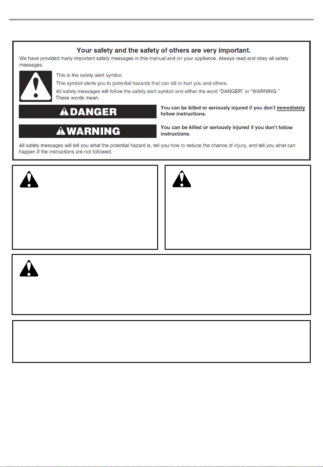
OUTDOOR BUILT-IN SIDE SEARING BURNER SAFETY
DANGER
If you smell gas:
1. Shut off gas to the appliance.
2. Extinguish any open flame.
1. Do not store or use gasoline or other
WARNING
flammable liquids or vapors in the
vicinity of this or any other appliance.
3. Open lid.
4. If odor continues, keep away from the
appliance and immediately call your gas
supplier or your fire department.
2. An LP cylinder not connected for use
shall not be stored in the vicinity of this
or any other appliance.
CALIFORNIA RESIDENTS ONLY - WARNING:
This product and the fuels used to operate this product (liquid propane), and the products of
combustion of such fuels, can expose you to chemicals including benzene, which is known
to the State of California to cause cancer and reproductive harm.
For more information go to: www.P65War ni ngs. ca.g o v .
In the State of Massachus etts, the following installation in str uctio n s apply:
Installations and repairs must be perform ed by a qualified o r licensed contractor , plumber, or gasfitter qualified o r licensed
by the State of Massachusetts.
If using a ball valve, it shall be a T-handle type.
A flexible gas co nn ector , when used, must not ex ceed 3 feet.
IMPORTANT: This grill is manufactured for outdo or use only. For grills that are to be used at elevations a bove 2,000 ft (609.6 m)
orifice conversion is required. See “Gas Supply Requirements” section. It is the responsibility of the installer to comply with the
minimum installation clearances specif ied on the model/ ser ial rating plate. The model /s erial rating plate for freestanding m odels
can be found on the lef t-hand cab inet door.
3

IMPORTANT SAFETY INSTRUCTIONS
WARNING: To reduce the risk of fire, electrical shock,
Injury to persons, or damage when using the outdoor cooking
gas appliance, follow basic precautions, including the
following:
Do not install portable or built-in outdoor cooking gas
appliances in or on a recreatio nal vehicle, po r tabl e trailer,
boat or in any other m oving installation.
Always maintain minimum clearances from combustible
construction, see “ Location Requirements” section.
The outdoor cooking gas appliance shall not be located
under overhead unprotected combustibl e construction.
This outdoor cooking gas appliance shall be used only
outdoors and shall not be used in a building, garage, or
any other enclosed area.
Keep any electrical supply cord and fuel supply hose
away from any heated surfaces.
Keep outdoor cooking gas appliance area cl ear and free
from combustible material, gasoli ne and other flammable
vapors and liquids.
Do not obstruct the flow of combustion and ventilation air.
Keep the ventilation openings of the cylinder enclosure
free and clear from debris.
Inspect the gas cylinder supply hose before each use of
the outdoor cooking gas appliance. If the hose shows
excessive abrasion or wear, or is cut, it MUST be
replaced before using the outdoor cooking gas appliance.
Contact your dealer and use only replacement hoses
specified for use with the outdoor cooking gas appliance.
Visually check the burner flames.
They should be blue. Slight
yellow tipping is normal for
LP gas. The flames should
be approxim atel y 1" (2.5 c m) hig h.
Check and clean burner/venturi tube for insects and
insect nest. A clogged tube can lead to fire under the
outdoor cooking gas appliance.
The LP gas supply cylinder to be used must be:
- constructed and marked i n accordance w ith the
Specification for LP Gas cylinders of the U.S.
Department of Transportation (DOT) or the National
Standard of Canada, CAN/CSA-B 339, Cylinder s,
Spheres, and Tubes for Transportation of Dangerous
Goods; and Commission.
- provided with a listed overfilling prevention device.
- provided with a cylinder connection devi ce compatibl e
with the connection for outdoor cooking gas appliances.
Always check connections for leaks each time you
connect and disconnect the LP gas supply cylinder. See
“Installation Instructi ons” secti on.
When the outd oor cook ing gas applianc e is not in use, the
gas must be turned off at the supply cylinder.
Storage of an outdoor cooking gas appliance indoors is
permissible only if the cylinder is disconnected and
removed from the outdoor co o k ing gas appliance.
Cylinders must be stored outdoors and out of the reach of
children and must not be stored in a building, garage, or
any other enclosed area.
The pressure regulator and hose assembly supplied with
the outdoor cooking gas appliance must be used. A
replacement press ure regul ator and hose ass embly
specific to your model is avail abl e from your outdoor
cooking gas appliance dealer.
Gas cylinder must include a collar to protect the cylinder
valve.
For appliances desig ned to use a CGA791 connection:
Place a dust cap on cylinder valve outlet whenever the
cylinder is not in use. Only install the type of dust cap on
the cylinder va`lve outlet that is provided with the cylinder
valve. Other types of caps or plugs may result in leakage
of propane.
If the following information is not followed exactly, a fire
causing death or serious injury may occur.
Do not store a spare LP gas cylinder under or near this
outdoor cooking gas appliance.
Never fill the cylinder beyond 80 percent full.
SAVE THESE INSTRUCTIONS
4
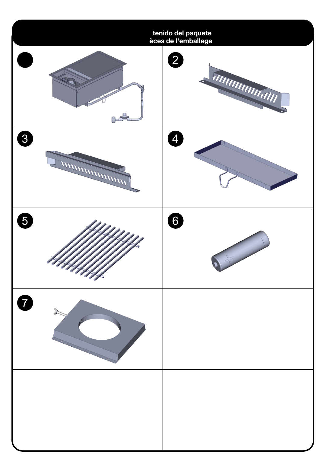
Package Parts List
Lista de contenido del paquete
Liste des pièces de l'emballage
1
3
2
4
5 6
7
5

ASSEMBLY INSTRUCTIONS/INSTRUCCIONES DE ENSAMBLAJE/CONSIGNES POUR L’ASSEMBLAGE
Tools Needed / Herramientas necesarias / Outillage Requis
Hardware package list / Lista de piezas / Liste de pièces
Truss Head Screw
Tornillo de cabeza
de armadura
Vis à tête bombée
5/32 - 32 x 3/8"
Some parts come
with Screws preinstalled.
Loosen and tighten
for final assembly.
A x5
Algunas partes
vienen con los
tornillos pre
instalados.
Afloje y apriete para
el ensamble final.
Flat Washer
Arandela plana
Rondelle plate
5/32"
Certaines pièces
sont livrées avec les
vis pré-installées.
Desserrez et
resserrez pour
l'assemblage final.
x4
B
1.
1
6

2.
3.
7
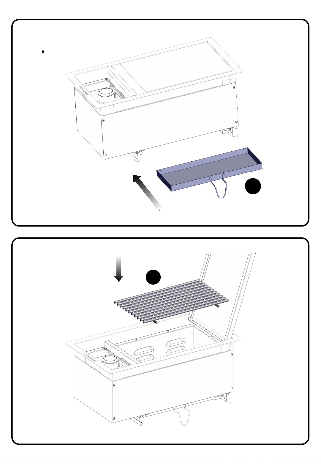
4.
4
5.
5
8
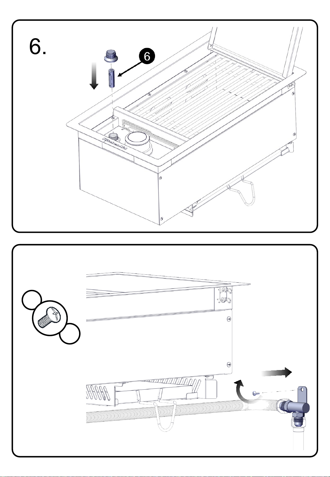
6.
7.
A
x1
9

8.
A
B
x4
x4
7
10

INSTALLATION REQUIREMENTS
Tools and Parts
Gather the required tools and par ts before star ting install atio n. Read and fo llow th e instructio ns p rovided with any tools li sted
here.
Configuration: Stand-Alone Side Searing Burner (760-0024)
Tools needed
Tape Measure
Small, flat-blade screwdriver
Flat-blade screwdriver
#2 and #3 Phillips screwdriver
Level
Parts Supplied for 20 lb LP Gas Installation
Gas pressure regulator/hos e assembly set for 11" WCP LP gas
LP gas fuel tank tray
Parts Supplied for Conversion to Natural Gas
2.08 mm Natural gas orifice for side searing burner (Model 760-0024)
Parts Needed for Conversion to Natural Gas
Natural gas conversi on ki t (Order Part Number 710-0003). Natural gas conversion kit includes:
Natural gas regulato r (mark ed “Natural Gas Regu lator”)
10 ft (3.0 m) PVC flex ible g as s uppl y hose with quick
connector
5.9 in. NG regulator hose
Gas line shut off valve
½" male pipe thread nipple for connection to pressure regulator
LP gas-resistant pipe-joint compound
CSA design-certifi ed ou tdoor flexi ble stainless s teel appliance conn ector (4-5 ft [1.2-1.5 m]) or rigid gas supply line as
needed
Wrench or pliers
Pipe wrench
Scissors or cutting pliers (to remove tiedowns)
Noncorrosive leak-detection soluti on
6 mm wrench
6 mm nut driver
Hex key
11

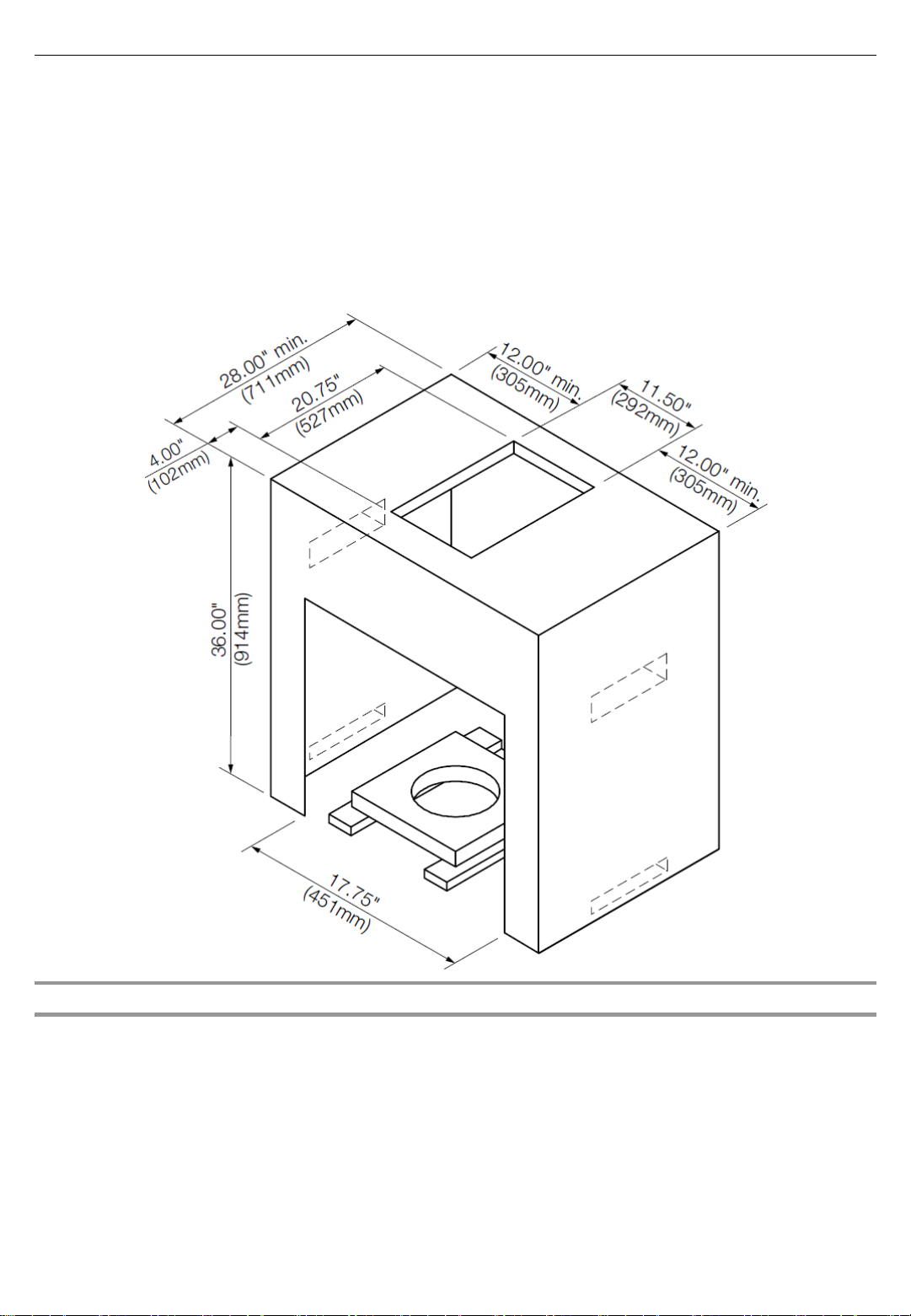
Location Requirements
Product Dimensions
Built-In Outdoor
Side Searing Burner Enclosure
Select a location that provides minimum exposure to wind and
traffic paths. The location should be away from strong draft
areas.
Do not obstruct flow of combustion and ventilation air.
Clearance to comb us tible construction for burner:
A minimum of 36” (92 cm) must be ma inta ine d b etw een
the front, sides and back of the burner and any
combustible co nstr uct io n.
A 36” (92 cm) minimum clearance must also be
maintained below the cooking surface, and the burner
shall not be used under overhead combustible
construction.
The enclosure for the built-in outdoor side searing burner is to
be a minimum of 7.3" (18.4 cm) high x 16.8" (42.6 cm) deep x
11.5" (29.2 cm) wide.
This built-in outdoor side searing burner is only for installation
in a built-in enclosure constructed only of non-combustible
materials. Non-combustible materials could be brick, firewall
or steel. Do not use wood or other com bustibl e mater ials for
built-in enclosure.
12
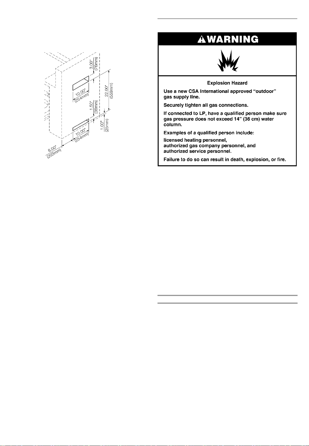
Cabinet Cutout Dimensions
The illustration below includes cutout dimensions and minimum spacing requirements. The illustration is for refer ence. The design
of your cabinet layout can be personalized, but the dimensions for the cutouts and minimum spacing must be followed.
Counter or support surfaces must be level.
The installation of this side searing burner must conform with local codes or, in the absence of local codes, with either the
National Fuel Gas Code, ANS I Z223.1/ NP FA 54, Natur al G as and Pr opa ne Ins tal la tio n Code, CSA B 149.1, or Pro pa ne Sto r age
and Handling
Code, B149.2.
NOTE: The outdoor side buner drops into the enclosure opening and is supported by its side flanges. Do not use a bottom
support.
Built-in Outdoor Side Searing Burner Enclosure Ventilation for LP Gas
Any enclosure i s to be vent ilated by openings at both the to p
and lower levels of the enclosure. The following information is
the minimum for proper ventilation of your island construction.
The island m us t be ven ted in o n e of the 2 foll owi n g ways:
A 90°or a 180°ventilation in the i slan d to ensure that air
flows through the island at either 90°or 180°.
Any enclosure for built-in ins tallati on is to have at least
There should be a minimum of 1 7/8" (4.4 cm) of
clearance fro m the bottom o f the m ain burn er bo wl
assembly island for proper ventilation.
NOTE: There should be no solid surface underneath th e
firebox portion of the side searing burner.
A minimum of 3" (7.6 cm ) is requ ired between the back
of the side searing burner an d any noncom bustibl e
one ventilation opening on an expo sed exter io r si de
located within 2½" (6 .0 cm ) of the to p and i s to be a
minimum of 20 in.
within 1½" (3 .0 cm ) o f the bo ttom o f the enclos u re, and
the bottom opening is to be a minimum of 10 in.
cm
opening is to be a min im um of 1 /8" (0 .32 cm ) wide.
materials. A minim u m o f 36" (92 cm ) is requ ired between
the back of the side seari ng burner and any combustible
material.
13
2
(129.0 cm2). One ventilation opening
2
2
). All vent openings are to be unobstructed. Ever y
(64.5
To ensure that the side searing burner operates properly,
it is recommended th at the is land h ave ventilation on all 4
sides as shown in the following illustration . The ventilation
holes should be as diagrammed to ensure adequ ate
ventilation for your side searing burner and island.
Gas Supply Requirements
Proper ventilatio n is a required based on the above
mentioned specificati ons f or your side searing burn er to
operate properly.
Observe all governi ng codes and ordinance s.
IMPORTANT: This installation must conform with all local
codes and ordinances. In the absence o f local cod es,
installation mus t conform wi th American Nation al Stand ard,
National Fuel Gas Co de ANSI Z223.1 -latest edition or
CAN/CGA B149.1 – latest edition.
IMPORTANT: The side searing burner must be connected to a
regulated gas supply.
Refer to the model/ser ial rating plate for inform ati on on the
type of gas that can be used. If this information does n ot agre e
with the type of gas available, check with yo ur local gas
supplier.
Gas Conversion:
No attempt shall be made to co nver t the s ide sear ing burner
from the gas specifi ed on the model/serial ratin g pl ate fo r u se
with a different gas type without consul ting th e serving g as
supplier. The conversion kit supplied with side searing burner
must be used. See “Gas Conversions” section fo r instructions.
Gas Pressure Regulator
A gas pressure regulator with the following pressure settings
must be used with the side searing burn er. The inlet (s upply)
pressure to the regulator should be as follows for proper
operation:
LP Gas:
Operating pressur e: 11 " (27.9 cm ) WCP
Inlet (supply) pressure: 11" to 14" (27.9 cm to 35.5 cm) WCP
Natural Gas:
Operating pres sur e: 4" (10.2 cm) WCP
Inlet (supply) pressure: 7" to 14" (17.8 cm to 35.5 cm) WCP
maximum.
Contact local gas supplier if you are not sure about the inlet
(supply) pressure.
14
Burner Requirements for High Altitude
20 lb LP Gas Fuel Tank
Input ratings shown on the model/s erial rati ng plate are fo r
elevations up to 2,000 ft. (609.6 m).
For elevations above 2,00 0 ft. (609.6 m), ratings are reduced at
a rate of 4% for each 1,0 00 f t. (304 .8 m ) above sea level.
Orifice conversion is required. See “Assistance” section to
order.
Gas Supply Line Pressure Testing
Testing above 1/2 psi (3.5 kPa) or 14" (35.5 cm) WCP
(gauge):
The side searing burner and its individual shutoff valve must
be disconnected fro m the gas supply piping system during
any pressure testing o f that system at test press ures greater
than 1/2 psi (3.5 kPa).
Testing below 1/2 psi (3.5 kPa) or 14" (35.5 cm) WCP
(gauge) or lower:
The side searing burner must be isolated fr om the g as suppl y
piping system by closing its individual manual shutoff valve
during any pressure testing of the gas suppl y pipi ng sy stem at
test pressures equal to o r les s th an 1/ 2 ps i (3. 5 k Pa).
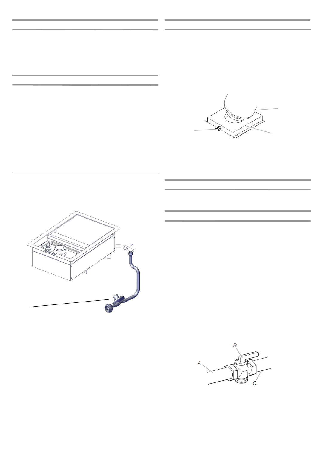
Gas Connection Requirements
This side seari ng burner is equipped for u se with a 20 l b LP
gas fuel tank (fu el tank not s uppli ed). A gas pressure
regulator/hose assembly is supplied.
The 20 lb LP gas fu el tan k m us t be m ou nted an d secur ed.
1. Open cabinet doors (if applicable).
2. Loosen the tank tray locking scr ew.
3. Place the 20 lb LP gas fuel tank bottom co ll ar in to th e
mounting ho le in the tan k tr ay.
4. Tighten the locking screw against the bottom collar o f the
20 lb LP gas fuel tank to secure.
5. Close cabinet doors (if applicable).
B
A
A. Locking screw
B. Tank tray
C. 20 lb LP gas fuel tank tray
C
Make sure the tank is firmly secured in an upright position.
LP Gas Conversion Using a Local LP Gas Supply
If you want to convert to local LP gas supply, con tact your
local gas company fo r specific instr uctio ns .
A
A. Gas pressure regulator/hose assembly
It is also design-certified by C SA Internatio n al for local LP gas
supply or for Natural gas with appropriate conversion.
Natural Gas Conversion
Conversion must be made by a qualified gas techn icia n . The
qualified Natural gas technicia n shall provi de the Natural gas
supply to the selected side searing burner location in
accordance with the National Fu el Gas Co de ANSI
Z223.1/NFPA 54 - latest edition, and local codes. For
conversion to Natural gas, the Natural Gas Conversion Kit
supplied with the side searing burn er mus t be used. See the
“Gas Conversions” section.
IMPORTANT: The gas i nstal lation must confor m wi th lo cal
codes, or in the absence of local codes, with the National Fuel
Gas Code, ANSI Z223.1/NFPA 54 - latest edition.
The gas supply line shal l be equipped with an approved
shutoff valve. This v alve s houl d be located in the same area as
the side searing bu rner and s ho uld be in a location that allows
ease of opening and closing. Do n ot bl o ck acces s to the
shutoff valve. The valve is for turning on or shutting off gas to
the side searing burner.
15
A. Gas supply line
B. Shutoff valve “open” position
C. To side searing burner

INSTALLATION INSTRUCTIONS
Built-in Outdoor Side Searing Burner
Installation
Unpack side searing burner. R emove al l packaging
materials and remove sid e searing burner f rom carton.
Place side searing burner into outdoor enclos ure, but
leave enough r oo m in back to connect to gas supply.
Install 20 lb LP Gas Fuel Tank Tray
The tank tray shou ld be s ecured to a fixed location that can be
easily accessed and will allow the gas pressure regulator/ hose
assembly to connect to the 20 lb LP gas fuel tank without
kinking or putting strain on the gas pressure regulator/ hose
assembly.
1. Place the tank tray in a location that can be secur ed using
4 screws (supplied) through the predrilled hol es.
2. Use 4 screws to secure the tank tray. T h e typical location
for a 20 lb LP gas fuel tank is within the enclosure where
the tank can be turned on an d of f easil y.
Make Gas Connection
NOTE: If side searing burner is to be converted to Natu ral g as,
follow instructions in the “Gas Conversions” section.
20 lb LP Gas Fuel Tank
IMPORTANT: A 20 lb LP gas fu el tan k m u st be pur chas ed
separately.
A. Four 5/32-32 x 3/8” truss head screws
NOTE: A bracket or shelf (no t su ppli ed) that is large enough t o
keep a second 20 lbLP gas fuel tank from being sto red i n the
storage area under the side searing burner is required to be
mounted inside the island.
IMPORTANT: The 20 lb L P gas f uel tan k mu st be m o unted
and secured.
IMPORTANT: The gas pressure regulator/hose assembly
supplied with the burner mus t be used. Replacement gas
pressure regulator/hose assembly specific to your model is
available from your outdoor grill dealer.
To Connect the 20 lb LP Gas Fuel Tank:
1. Check that the 20 lb LP gas fuel tank is in the “OF F ”
position. If not, turn the valve clockwise until it stops.
2. Check that the 20 lb LP gas fuel tank valve has the proper
type-1 external male thread connectio ns per ANSI
Z21.81.
3. Check that the burner control k no bs ar e in the “OF F”
position.
4. Remove any debris and inspect the valve connections,
port, and gas pressure regulator/hose assembly for
damage.
NOTE: Always keep the LP cylinder at 90°(upright)
orientation to provide vapor withdrawal.
16
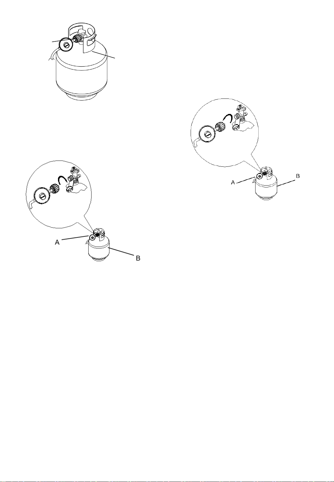
To Disconnect the 20 lb LP Gas Fuel Tank:
A
B
A. Gas pressure regulator/hose assembly
B. 20 lb LP gas fuel tank
5. Using your hand, turn the gas pressure regulator/hose
assembly clock wis e to connect to the 20 lb LP gas fuel
tank as shown.
Hand tighten only. Us e of a wrench could damag e the
quick coupling nut.
1. Check that the burner control k no bs ar e in the “OF F”
position and the side searing burner is cool.
2. Check that the 20 lb LP gas fuel tank is in the “OF F ”
position. If not, turn the valve clockwise until it stops.
3. Using your hand, turn the gas pressure regulator/hose
assembly counterclo ckwise to disconnect to the 20 lb LP
gas fuel tank as sh own .
Hand loosen o nl y. U se o f a wr ench could damage the
quick coupling nut.
A. Gas pressure regulator/hose assembly
B. 20 lb LP gas fuel tank
4. Place dust cap on cylinder valve outlet whenever the
cylinder is not in use. Only install the type of dust cap on
the valve outlet that i s pr ov ided with the cylinder valve.
Other types of caps or plugs may resul t in leakage o f
propane.
A. Gas pressure regulator/hose assembly
B. 20 lb LP gas fuel tank
Make sure that the cylinder valve connection device
properly mates with the connection device attached to
the inlet of the pressu re regulator.
6. Open the tank valve fully by turn ing th e valv e
counterclockwi se. Wait a few minu tes for gas to move
through the gas line.
7. Before lighting the side searing burner, test all
connections by brushing on an appro ved noncorrosive
leak-detection soluti on. Bubbl es will show a leak.
8. If a leak is found, turn the tank valv e of f and do no t us e
the side searing burner. Co ntact a qualifi ed g as
technician to make repairs.
17

GAS CONVERSIONS
Gas Connection to Natural Gas
This installatio n mus t conform with local co des and
ordinances. In the absence of local codes, installati ons m ust
conform with either th e National F uel Gas Co de ANSI Z223.1 latest edition, or CAN/CGAB 149. 1 Natu ral Gas and Propan e
installation code.
Copies of the standar ds listed above may be obtain ed from:
CSA International
8501 East Pleasant Valley Rd.
Cleveland, Ohio 44131-5575
National Fire Protection Associ ation
One Batterymarch Park
Quincy, Massachusetts 02269
Tools and Parts for Gas Conversion
Gather the required tools and par ts before star ting install atio n.
Read and follow the instructio ns pro vided with any to ols l isted
here.
Tools needed
6mm
Parts supplied
Natural gas orifices
Parts needed
Natural gas conversion kit Part Number 710-0003. See
“Assistance” section to order. The conversion kit includes:
Natural gas regulator 4" W.C. (marked “Natural Gas
Regulator”)
10 ft (3.0 m) Natural gas hose with quick connector
5.9" (150 mm) Natural gas regulator ho se
6 mm nut driver
6 mm wrench
Hex key
IMPORTANT: Gas conversi o ns must be done by a qualified
installer. Before proceeding with conversio n, shut off the gas
supply to the side searing burn er.
18

Conversion from LP Gas to
Natural Gas
Orifice Change and the Installation of the NG regulator
1. Turn off the main gas supply valve.
2. Disconnect 20 lb LP gas fuel tank (if pr esent).
3. Turn off burner control valve.
4. Use screwdriver to remove screw holding the corrug ated
pipe connector to the encl o sur e.
5. Use adjustable wrench to remove hose and regulator from
corrugated pipe connector.
8. Lift the burner starting fro m the back, as sh own .
9. Use 6 mm socket wrench or 6 mm nut driver to r emo v e
the orifice.
6. Remove side searing burner cooking grid.
7. Use a screwdriver to remove one screw from ignitor pin
and two screws o n th e rear o f the si de seari ng burner.
10. Replace with natural gas orifice.
11. Reinstall sear burner. Tighten the sear burner orifice brass
connector and sear burner tu be by using a wrench.
IMPORTANT: Check that the or if ice is pro perly installed
inside of the side searing burner gas valve.
19

12. Reinstall the two screws to the rear of the searing bu rner
and one screw to the iginitor pin.
13. Replace side searing burner cooking grid.
17. Use screwdriver to install screw to hold the corrugate
connector to th e enclo su re .
Record Conversion
The LP appliance nameplate is located on the fr on t si de of the
burner firebox. Once converted, place the NG appliance
nameplate over the current LP appliance nameplate.
In the last page of the Use and C are Gui de, write “Converted
to Natural Gas”. Als o r ecor d the co nv ersion date and the
technician/com pany that perfo rmed the conversion.
14. Use an adjustable wrench to ins tall Natural gas pressure
regulator and corrugated pipe to the corrugated pipe
connector.
15. Connect the brass connecto r on one end of the 10 ft (3.0
m) PVC flexible gas su pply hose to the Natural gas
pressure regulator (A).
A
16. Connect the quick connector on the other end of the 10 ft
(3.0 m) PVC flexible gas supply hose to the rigid Natural
gas supply pipe (B).
B
20
USING YOUR SIDE SEARING BURNER
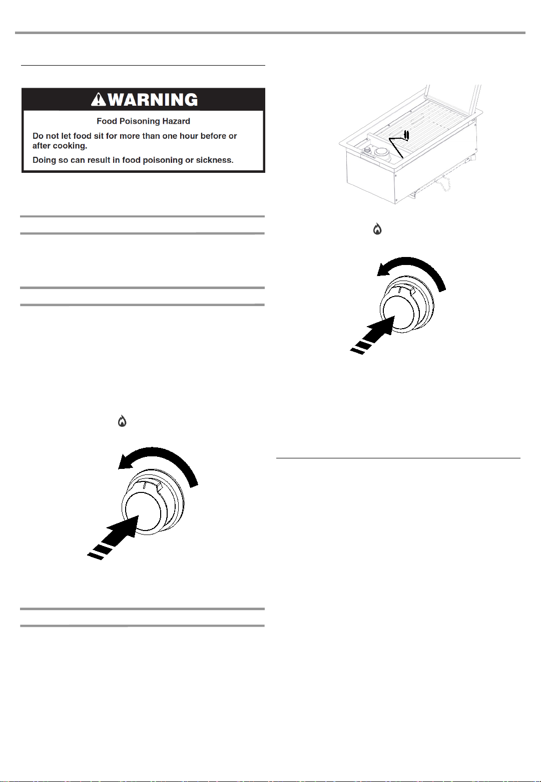
Lighting the Side Searing Burner
1. Open the lid completely.
2. Make sure control knob is tur ned to “○”.
3. Turn the gas supply on.
Natural gas or LP gas from a local supply
Using gas supply source other than 20 lb LP gas fuel tank:
Turn the shutoff valve to open position from the front of
gas supply line. The valve is open when the handle is
parallel to the gas pipe.
20 lb LP gas fuel tank
See the “Gas Supply Requirements” section.
Using a 20 lb LP gas fu el tank :
Slowly open the tank valve.
NOTE: If flow limiting device activates, your grill may not
light. If your grill does light, the flames will be low and will
not heat properly. Turn tank valve and all contr ol kn obs o ff
and wait 30 seconds. After shutting off th e tank , ver y
slowly open tank valve an d wait 5 seconds befo re ligh ting.
4. Do not lean over the side searing burner. Push in and turn
the burner knob to “ ” and hold in. Th e burn er wil l li g ht
immediately. Wh en bu rner is l it, tu rn kn ob t o des ired
setting.
4. Guide the lit match to the burner to lig ht.
5. Do not lean over the side searing burner. Push in and turn
the burner knob to “ ”. The burner will light immediately.
Hold this knob in for 10 seconds after the burner is lit.
Turn knob to desired setting.
6. Remove match and replace manual lighting exten sion on
the right side panel.
IMPORTANT:
If burner does not l ig ht i mm ediatel y, turn the burner knob to
“
○” and wait 5 minutes before relighti ng.
If burner does not light after attempti ng to lig ht them manuall y,
contact the Custom er Ser vi ce C enter . See the “As sis ta nc e”
section.
IMPORTANT:
If burner does not l ig ht i mm ediatel y, turn the burner knob to
“
○” and wait 5 minutes before relighti ng.
Manually Lighting the Side Searing Burner
1. Open the lid completely.
2. Remove the manual lighting extensi on and attach a match
to the split ring.
3. Strike the match to light it.
Using the Side Searing Burner
Grilling with Infrared heat produces a high heat which quickly
chars foods. Searing creates and lock s in flavo rs on the
outside and creates a beautifully- browned surface and texture.
The result is a crisp, flavorful outside with a tender, juicy inside.
Lift the lid on the infrared side sear burner
Check that the sear grill grate is in place before using the
sear burner
Turn on the sear burner and preheat for 5 minutes
Ensure that foods are fully thawed and that excess fat is
trimmed off prior to searing
Place food on sear g rate. Sear fo o d fo r 1 to 2 min utes on
each side, then m o ve th e fo o d to th e m ain g ri ll co o ki ng
surface to finish grilling to desired doneness
Turn off the side sear b urn er and al lo w burner to cool
before closing lid
21
 Loading...