

KitchenAid 730-0745B Installation Instructions And Use & Care Manual
FREESTANDING OUTDOOR GRILL
7
20-0745B (LP) 730-0745B (NG)
Installation Instructions and Use & Care Guide
For questions about features, operation/performance, parts, accessories or service, call: 1-877-373-2301
or visit our website at www.Kitchenaidgrills.com
ASADOR AUTÓNOMO P
Instruccione
Pa
ra consultas respecto a características, funcionamiento, rendimiento, piezas, accesorios o servicio técnico, llame al: 1-877-373-2301
s de instalación y Manual de uso y cuidado
o visite nuestro sitio de internet en www.Kitchenaidgrills.com
ARA EXTERIOR
COMPTOIR POUR GRIL D'EXTÉRIEUR
AUTOPORTANT
Instructions d’installation et Guide d’utilisation et d’entretien
Pour des questions à propos des caractéristiques, du fonctionnement/rendement, des pièces, des accessoires ou du service,
composer le : 1-877-373-2301
ou visitez notre site web www.Kitchenaidgrills.com
able of Contents/Índice/Table des matières..................................................................2
T
19000429A1

TABLE OF CONTENTS
OUTDOOR GRILL SAFETY………………………………3
INSTALLATION REQUIREMENTS………………………....5
Tools and Parts……………...…………………………………5
Location requirements…………………………………..…….5
Product Dimensions……………………………….………….6
Gas Supply Requirements……………………………………7
Gas Connection Requirements………………………………7
REPLACEMENT PARTS……………………………………9
ALL PRE-ASSEMBLY LIST……………...………………….11
PACKAGE CONTENTS LIST…………………...……………12
INSTALLATION INSTRUCTIONS…………………….…...…13
Freestanding Outdoor Grill Installation…………………….13
Make Gas Connection…………………………...……..……16
GAS CONVERSION………………………………….............19
Tools and Parts for Gas Conversion …………………....19
Conversion from LP Gas to Natural Gas………………….19
Check and Adjust the burners………………………….……22
ÍNDICE
OUTDOOR GRILL USE …………………………………………23
Using Your Outdoor Grill ………………………………..….…23
Using Your Side Burner…………………………………..……25
TIPS FOR OUTDOOR GRILLING ……………………….…..26
Cooking Methods ………………….………………………...….27
Grilling Chart ………………………….……………………....….27
OUTDOOR GRILL CARE …………………………………..…29
Replacing the Igniter Battery …….………………….………....29
General Cleaning ………………………………………..........…29
TROUBLE SHOOTING .........................................................31
ASSISTANCE ……………………………………………..……31
Accessories………………………………………………………..31
WARRANTY …………………………………………….…..…….32
SEGURIDAD DEL ASADOR PARA EXTERIORE….......35
REQUISITOS DE INSTALACIÓN…………..………………..37
Herramientas y piezas ……………...………………...……….37
Requisitos de ubicación ……………………………...……….37
Medidas del producto ……………………………….………38
Requisitos del suministro de gas ………………………….....39
Requisitos para la conexión de gas …………………...…….40
PIEZAS DE REPUESTO ……………………………...………41
Tools los Tornillospre-ensambladoslisto………………..….44
PaqueteListaDe Contenido………………….............……45
INSTRUCCIONES DE INSTALACIÓN ……………….……..46
Instalación del asador autónomo para exteriores .........….46
Conexión del suministro de gas ………………………50
CONVERSIONES DE GAS ……………………………..….52
Herramientas y piezas para la conversión de gas ..........….52
Conversión de gas LP a gas natural …………………………52
Revise y regule los quemadores ……………………...……...55
TABLE DES MATIÈRES
SÉCURITÉ DU GRIL D'EXTÉRIEUR ………………….……68
EXIGENCES D’INSTALLATION …………………………..…70
Outils et pièces ……………...……………………………...….70
Exigences d'emplacement ……………………………………70
Dimensions du produit ……………………………………...…..71
Spécifications de l'alimentation en gaz ………………..……72
Exigences concernant le raccordement au gaz………………73
PIÈCES DE RECHANGE …………………………………...…74
Contenu du colis…………………………………………...…….78
Tous les pre-assembly liste vis……………………………..…..79
INSTRUCTIONS D’INSTALLATION ……………….……...….80
Installation du gril d’extérieur autoportant …………..………..80
Raccordement au gaz …………………………............…..….83
CONVERSIONS POUR CHANGEMENT DE GAZ …….…....85
Outils et pièces pour conversion de gaz ………….……..…...85
Conversion de propane à gaz naturel ……………….…...…...86
Contrôle et réglage des brûleurs ……………………….……...88
USO DEL ASADOR PARA EXTERIORES …………………...56
Cómo usar el asador para exteriores …………………………..56
Uso delmechero lateral…... …... …...……...………...58
CONSEJOS PARA ASAR AL AIRE LIBRE …………………..59
Métodos de cocción ………………………………………...…...59
Cuadro para asar ……………………………………………...….60
CUIDADO DEL ASADOR PARA EXTERIORES ………….….62
Cómo reemplazar la batería del encendedor …………………62
Limpieza general ………………………………………………….62
SOLUCIÓN DE PROBLEMAS.................................................64
ASISTENCIA………………………………………………..……..65
GARANTÍA …………………………………………………..…....65
UTILISATION DU GRIL D’EXTÉRIEUR …….………………...89
Utilisation du gril d’extérieur …………………………………….90
Utilisation de votre brûleur latéral……………………..………...91
CONSEILS POUR L'UTILISATION DU GRIL
D’EXTÉRIEUR……………………………………...……….….…92
Méthodes de cuisson ……………………………...………….…92
Tableau de cuisson au gril ………………………...……...….….93
ENTRETIEN DU GRIL D’EXTÉRIEUR ……………………...…96
Remplacement de la pile de l’allumeur ………………………..96
Nettoyage général …………………………………….……….…96
DÉPANNAGE........................................................................98
ASSISTANCE……………………………………………….……98
GARANTIE…………………………………………………...…....99
2
OUTDOOR GRILL SAFETY
You can be killed or seriously injured if you don't immediately
You
can
be killed or seriously injured if you don't
follow
All safety messages will tell you what the potential hazard is, tell you how to reduce the chance of injury, and tell you what can
happen if the instructions are not followed.
Your safety and the safety of others are very important.
We have provided many important safety messages in this manual and on your appliance. Always read and obey all safety
messages.
This is the safety alert symbol.
This symbol alerts you to potential hazards that can kill or hurt you and others.
All safety messages will follow the safety alert symbol and either the word “DANGER” or “WARNING.”
These words mean:
follow instructions.
instructions.
DANGER
W
ARNING
If you smell gas:
1. Shut off gas to the appliance.
2. Extinguish any open flame.
3. Open lid.
4. If odor continues, keep away from the
appliance and immediately call your
gas supplier or your fire department.
DANGER
W
ARNING
1. Do not store or use gasoline or other
flammable liquids or vapors in the
vicinity of this or any other appliance.
2. An LP cylinder not connected for use
shall not be stored in the vicinity of
this or any other appliance.
State of California Proposition 65 Warnings:
WARNING: This product contains one or more chemicals known to the State of California to cause cancer.
WARNING: This product contains one or more chemicals known to the State of California to cause birth defects or other
reproductive harm.
In the State of Massachusetts, the following installation instructions apply:
■
Installations and repairs must be performed by a qualified or licensed contractor, plumber, or gasfitter qualified or licensed by
the State of Massachusetts.
■
If using a ball valve, it shall be a T-handle type.
■
A flexible gas connector, when used, must not exceed 3 feet.
IMPOR
conversion is required. See “Gas Supply Requirements” section. It is the responsibility of the installer to comply with the minimum
installation clearances specified on the model/serial rating plate. The model/serial rating plate for freestanding models can be found
inside left-hand cabinet door.
TANT: This grill is manufactured for outdoor use only. For grills that are to be used at elevations above 2000 ft (609.6 m) orifice
3
SA
VE THESE INSTRUCTIONS
IMPORTANT SAFETY INSTRUCTIONS
WARNING:
To reduce the risk of fire, electrical shock,
injury to persons, or damage when using the outdoor cooking
gas appliance, follow basic precautions, including the
following:
■
Do not install portable or built-in outdoor cooking gas
appliances in or on a recreational vehicle, portable trailer,
boat or in any other moving installation.
■
Always maintain minimum clearances from combustible
construction, see “Location Requirements” section.
■
The outdoor cooking gas appliance shall not be located
under overhead unprotected combustible construction.
■
This outdoor cooking gas appliance shall be used only
outdoors and shall not be used in a building, garage, or any
other enclosed area.
■
Keep any electrical supply cord and fuel supply hose away
from any heated surfaces.
■
Keep outdoor cooking gas appliance area clear and free
from combustible materials, gasoline and other flammable
vapors and liquids.
■
Do not obstruct the flow of combustion and ventilation air.
Keep the ventilation openings of the cylinder enclosure free
and clear from debris.
■
Open the cabinet door and inspect the gas cylinder supply
hose before each use of the outdoor cooking gas
appliance. If the hose shows excessive abrasion or wear,
or is cut, it MUST be replaced before using the outdoor
cooking gas appliance. Contact your dealer and use only
replacement hoses specified for use with the outdoor
cooking gas appliance.
■
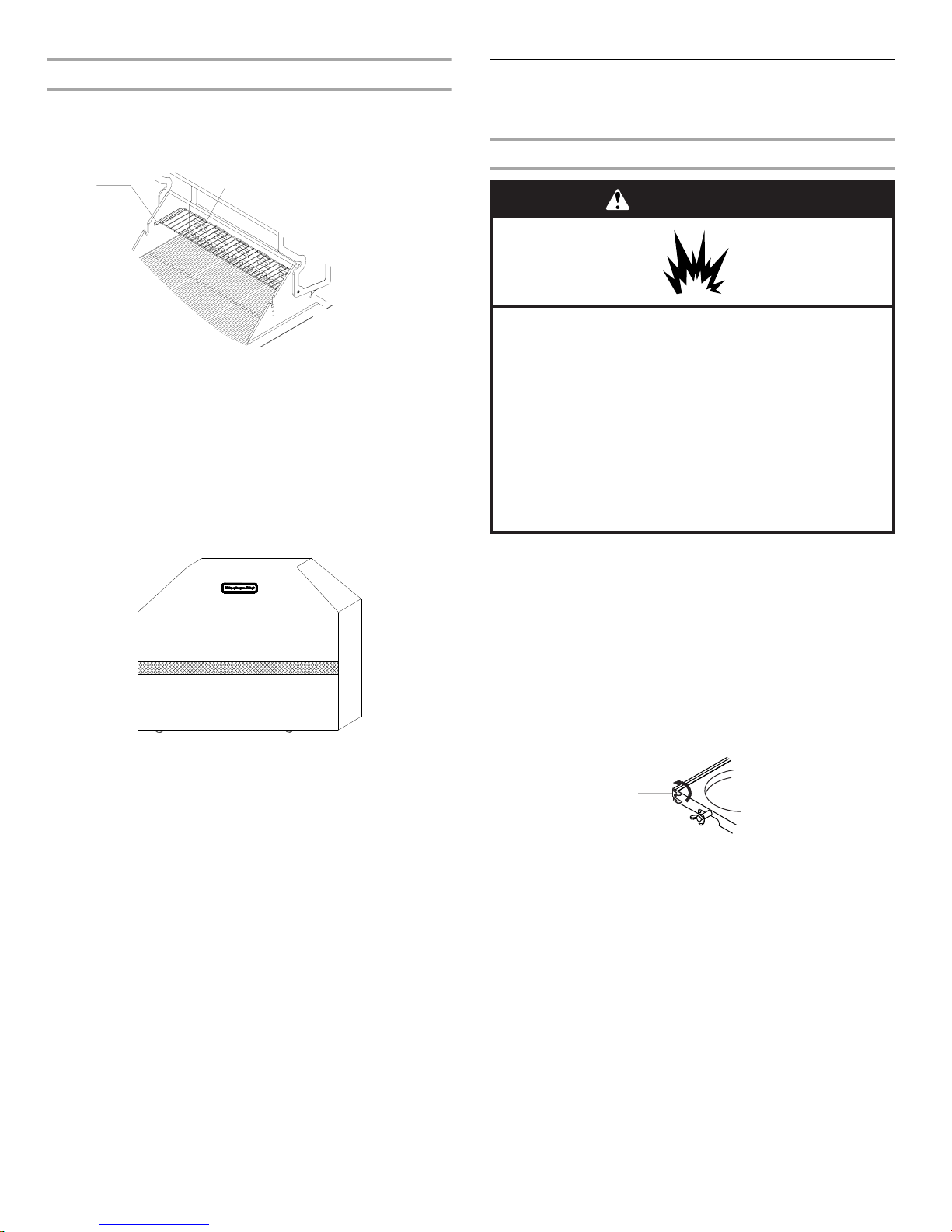
Visually check the burner flames.
They should be blue. Slight
yellow tipping is normal for LP
gas. The flames should be
approximately 1" (2.5 cm) high.
■
Check and clean burner/venturi tube for insects and insect
nest. A clogged tube can lead to fire under the outdoor
cooking gas appliance.
■
The LP gas supply cylinder to be used must be:
- constructed and marked in accordance with the
Specification for LP Gas Cylinders of the U.S. Department
of Transportation (DOT) or the National Standard of
Canada, CAN/CSA-B339, Cylinders, Spheres, and Tubes
for Transportation of Dangerous Goods; and Commission.
- provided with a listed overfilling prevention device.
- provided with a cylinder connection device compatible
with the connection for outdoor cooking gas appliances.
■
Always check connections for leaks each time you connect
and disconnect the LP gas supply cylinder. See
“Installation Instructions” section.
■
When the outdoor cooking gas appliance is not in use, the
gas must be turned off at the supply cylinder.
■
Storage of an outdoor cooking gas appliance indoors is
permissible only if the cylinder is disconnected and
removed from the outdoor cooking gas appliance.
■
Cylinders must be stored outdoors and out of the reach of
children and must not be stored in a building, garage, or
any other enclosed area.
■
The pressure regulator and hose assembly supplied with
the outdoor cooking gas appliance must be used. A
replacement pressure regulator and hose assembly
specific to your model is available from your outdoor
cooking gas appliance dealer.
■
Gas cylinder must include a collar to protect the cylinder
valve.
■
For appliances designed to use a CGA791 Connection:
Place a dust cap on cylinder valve outlet whenever the
cylinder is not in use. Only install the type of dust cap on
the cylinder valve outlet that is provided with the cylinder
valve. Other types of caps or plugs may result in leakage
of propane.
If the following information is not followed exactly, a fire
causing death or serious injury may occur.
■
Do not store a spare LP gas cylinder under or near this
outdoor cooking gas appliance.
■
Never fill the cylinder beyond 80 percent full.
1"
(2.5 cm)
4
INST
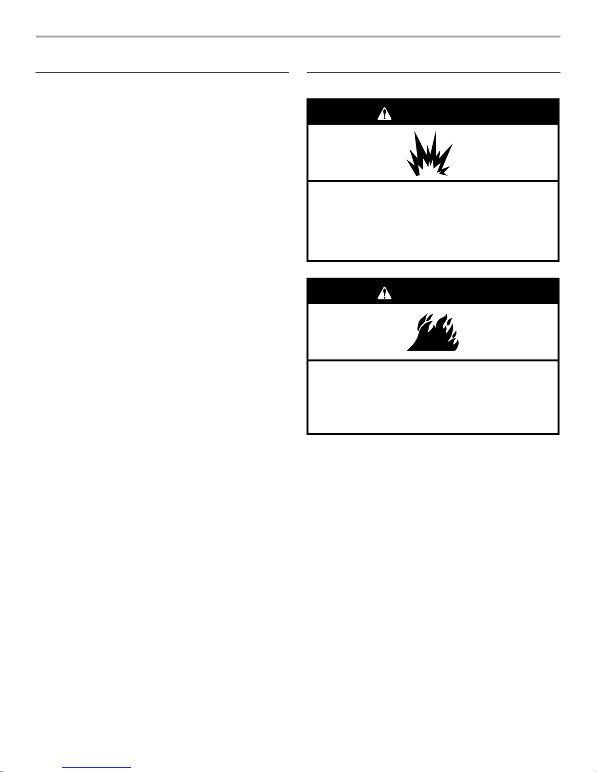
W
ARNING
Explosion Hazar
d
Do not store fuel tank in a garage or indoors.
Do not store grill with fuel tank in a garage or indoors.
Failure to follow these instructions can result in death,
explosion, or fire.
W
ARNING
Fire Hazard
Do not use grill near combustible materials.
Do not store combustible materials near grill.
Doing so can result in death or fire.
ALLATION REQUIREMENTS
T
ools and Parts
G
ather the required tools and parts before starting installation.
Read and follow the instructions provided with any tools listed
here.
ools Needed
T
■
Phillips screwdriver
■
W
rench or pliers
ench
Pipe wr
■
■
Scissors or cutting pliers
(to remove tiedowns)
■
Noncorr
detection solution
osive leak-
Parts Supplied
G
■
as pressure regulator/hose assembly set for 11" WCP LP
gas
■
Ri
ght side shelf with side burner
■
Left side shelf
Side bur
■
■
“AA” Batt
■
W
Cooking grid
■
■
Side bur
Par
ts Needed
■
20 lb LP gas fue
ner control knob
ery (1)
arming rack
ner cooking grid
l tank - approximately 18" (45.7 cm) height
Location Requirements
rts Needed for Conversion to Natural Gas
Pa
Nat
■
ural gas conversion kit Part Number 710-0003. See
“Assistance” section to order. The conversion kit includes:
Nat
■
ural gas regulator 4" W.C. (marked “Natural Gas
Regulator”)
■
■
■
■
■
■
G
■
½"
regulator.
LP gas-r
■
■
CSA design-cer
appliance connector (4-5 ft [1.2-1.5 m]) or rigid gas supply
line as needed.
(3.0 m) Natural gas hose with quick connector
10 ft
50 mm) Natural gas regulator hose
5.9" (1
6 mm
nut driver
6 mm
wrench
Hex key
as line shutoff valve
male pipe thread nipple for connection to pressure
esistant pipe-joint compound
tified outdoor flexible stainless steel
Se
lect a location that provides minimum exposure to wind and
traffic paths. The location should be away from strong draft
areas.
Do not obstruct flow of combustion and ventilation air.
Clearance to combustible construction for freestanding outdoor
grills:
■
A mi
nimum of 24" (61 cm) must be maintained between the
front of the grill hood, sides and back of the grill and any
combustible construction.
A 24" (61 cm)
■
below the cooking surface, and the grill shall not be used
under overhead combustible construction.
Rotiss
erie (accessory)*
If you equip your gri
clearance is needed for the rotisserie motor.
A grounded, 3-prong outlet located to the left of the grill is
required.
*See “Assistance” section to order.
minimum clearance must also be maintained
ll with a rotisserie, a 6" (15.2 cm) minimum
5

12
5/8"
(32cm)
Product Dimensions
55"
31"
(
1405cm)
(78
.74cm)
12 5/
(58.42cm)
(32cm)
23
"
8"
48
5/8"
(123.5cm)
6
Gas Supply Requirements
W
ARNING
Explosion Hazard
Use a new CSA International approved “outdoor”
gas supply line.
Securely tighten all gas connections.
If connected to LP, have a qualified person make sure
gas pressure does not exceed 14” water
column.
Examples of a qualified person include:
licensed heating personnel,
authorized gas company personnel, and
authorized service personnel.
Failure to do so can result in death, explosion, or fire.
A
A
Install a shut-off valve.
(36cm)
Obse
rve all governing codes and ordinances.
IMPORTANT: This installation must conform with all local codes
and ordinances. In the absence of local codes, installation must
conform with either the National Fuel Gas Code, ANSI Z223.1/
NFPA 54, Natural Gas and Propane Installation Code, CSA
B149.1, Propane Storage and Handling Code, B149.2, or the
Standard for Recreational Vehicles, ANSI A119.2/NFPA 1192 and
CSA Z240 RV Series Recreational Vehicle Code as applicable.
IMPORTANT: Grill must be connected to a regulated gas supply.
Refer to the model/serial rating plate for information on the type
of gas that can be used. If this information does not agree with
the type of gas available, check with your local gas supplier.
Gas Conversion:
No attempt shall be made to convert the grill from the gas
specified on the model/serial rating plate for use with a different
gas type without consulting the serving gas supplier. The
conversion kit supplied with grill must be used. See “Gas
Conversions” section for instructions.
Bur
ner Requirements for High Altitude
Input ratings s
elevations up to 2,000 ft (609.6 m).
For elevations above 2,000 ft (609.6 m), ratings are reduced at a
rate of 4% for each 1,000 ft (304.8 m) above sea level. Orifice
conversion is required. See “Assistance” section to order.
s Supply Line Pressure Testing
Ga
T
esting above ½ psi (3.5 kPa) or 14" (35.5 cm) WCP (gauge):
The grill and its individual shutoff valve must be disconnected
from the gas supply piping system during any pressure testing of
that system at test pressures greater than ½ psi (3.5 kPa).
Testing below ½ psi (3.5 kPa) or 14" (35.5 cm) WCP (gauge) or
lower:
The grill must be isolated from the gas supply piping system by
closing its individual manual shutoff valve during any pressure
testing of the gas supply piping system at test pressures equal to
or less than ½ psi (3.5 kPa).
hown on the model/serial rating plate are for
Gas Connection Requirements
0 lb LP Gas Fuel Tank
2
This grill is equipped for use with a 20 lb LP gas fuel tank (fuel
tank not supplied). A gas pressure regulator/hose assembly is
supplied.
Any brand of 20 lb LP gas fuel tank is acceptable for use with the
grill, provided that it is compatible with the grill’s retention means
(tank tray included).
It is also design-certified by CSA International for local LP gas
supply or for Natural gas with appropriate conversion.
Gas Pr
The gas pr
The inlet (supply) pressure to the regulator should be as follows
for proper operation:
LP Gas:
Operating pressure: 11" (27.9 cm) WCP
Inlet (supply) pressure: 11" to 14" (27.9 cm to 35.5 cm) WCP
Natural Gas:
Operating pressure: 4" (10.2 cm) WCP
Inlet (supply) pressure: 7" to 14" (17.8 cm to 35.5 cm) WCP
maximum.
Contact local gas supplier if you are not sure about the inlet
(supply) pressure.
essure Regulator
essure regulator supplied with this grill must be used.
Gas pressure regulator/hose assembly
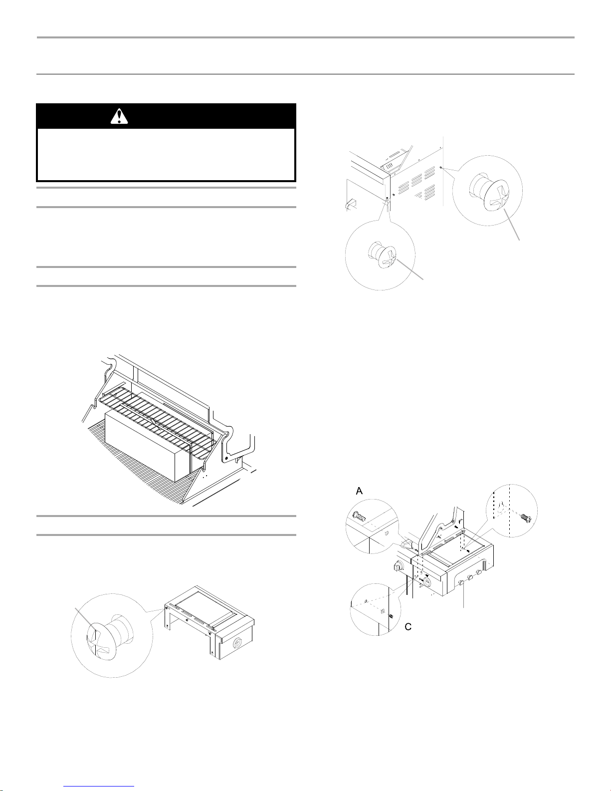
A.
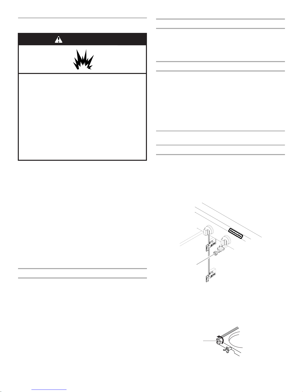
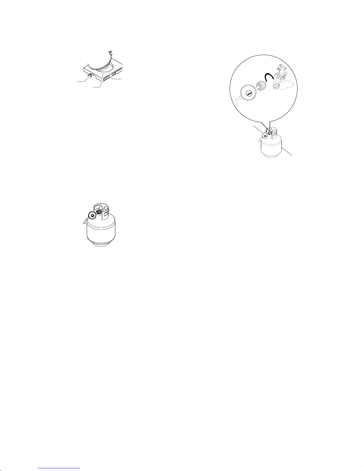
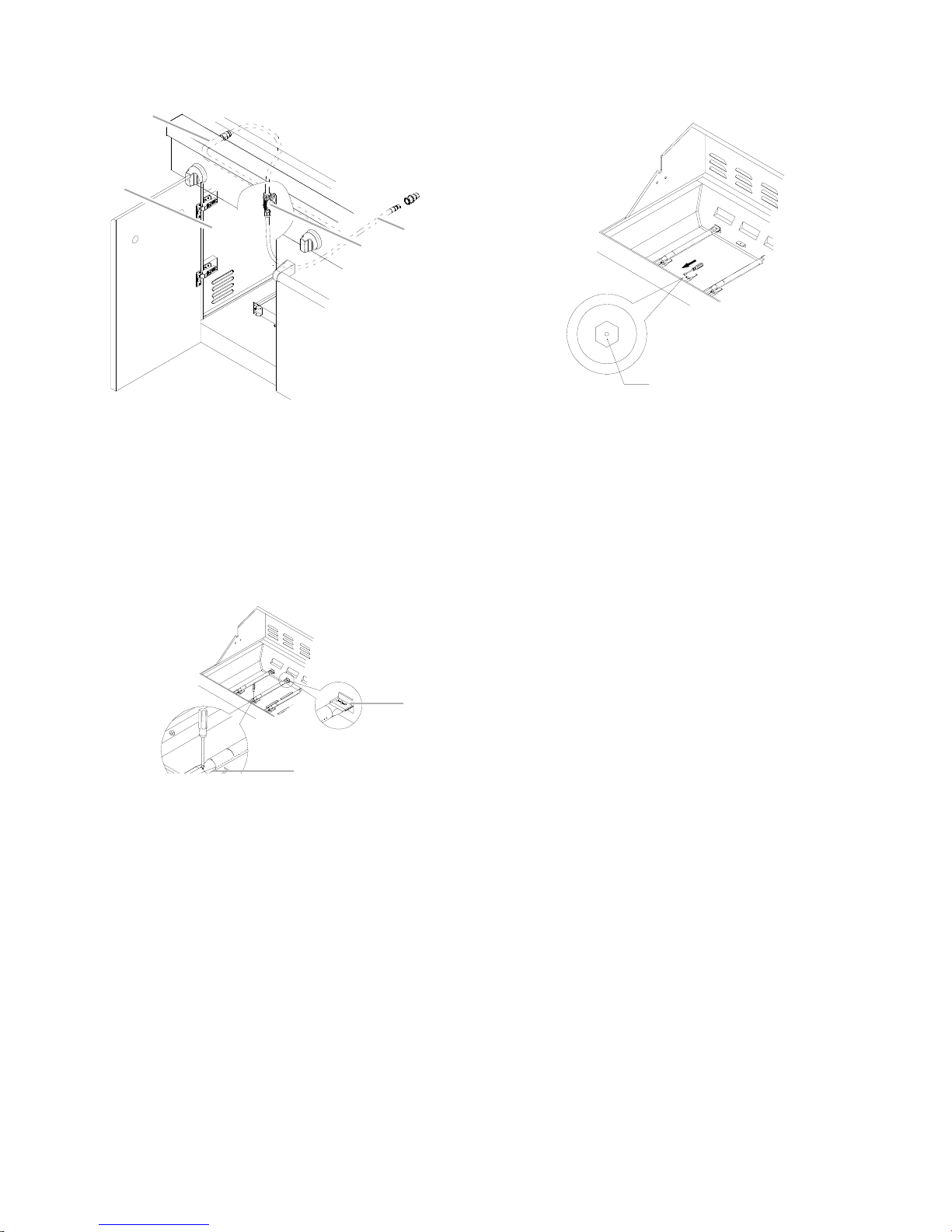
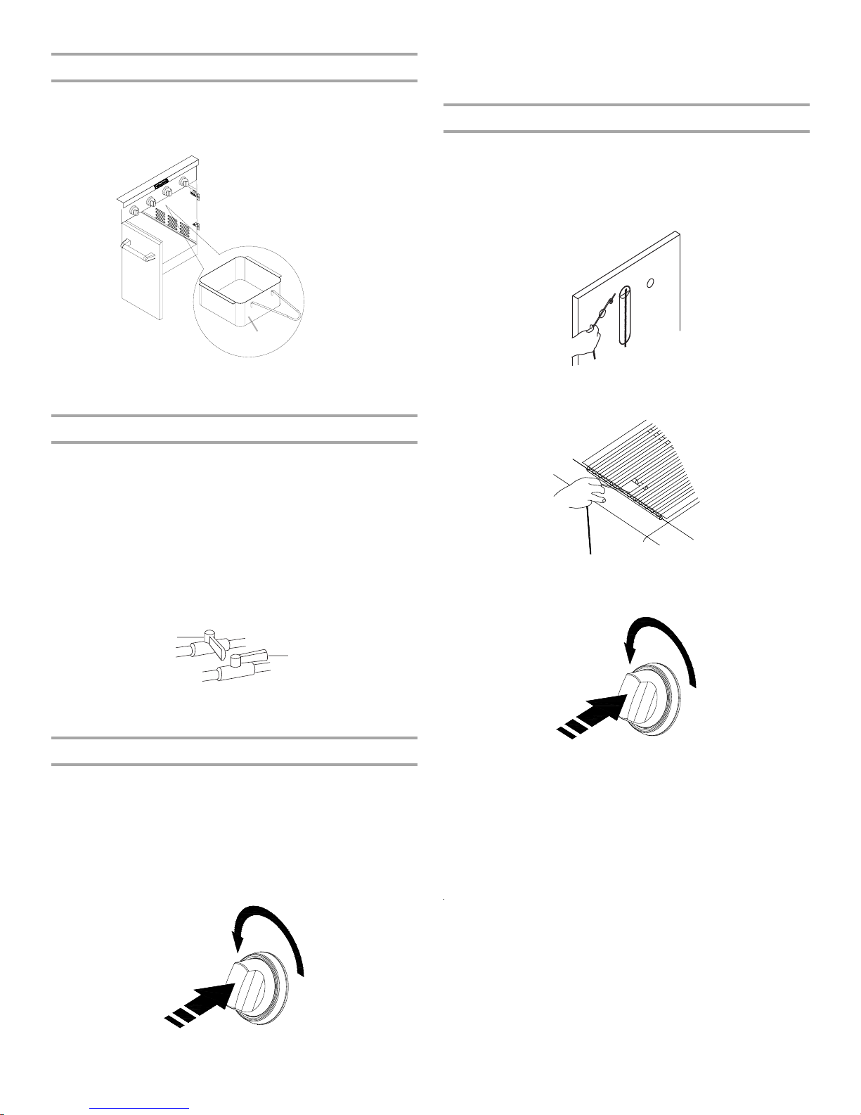
The 20 lb LP gas fuel tank must be mounted and secured.
Door Style Tank Tray
1. Open cabinet doors.
2. Slide the tank tray locking bracket counterclockwise 90° and
pull out the tray.
A. Tank tray locking bracket
7
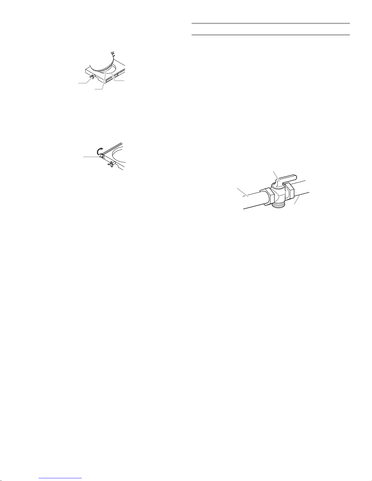
3. Place th
A
C
B
A
A
B
C
e 20 lb LP gas fuel tank bottom collar into the
mounting hole in the tank tray.
4. Tighten the locking screw against the bottom collar of the
20 lb LP gas fuel tank to secure.
A. Locking screw
B. Bottom collar
C. Mounting hole
5. Slide the drawer with the 20 lb LP gas fuel tank back into the
cabinet. Turn the tank tray locking bracket clockwise 90° to
tighten.
A. Tank tray locking bracket
Natu
ral Gas Conversion
version must be made by a qualified gas technician. The
Con
qualified Natural gas technician shall provide the Natural gas
supply to the selected grill location in accordance with the
National Fuel Gas Code ANSI Z223.1/NFPA 54 - latest edition,
and local codes. For conversion to Natural gas, the Natural Gas
Conversion Kit supplied with the grill (on some models) or the
Natural Gas Conversion Kit Part Number 710-0003 must be
used. See “Assistance” section for information on ordering.
IMPORTANT: The gas installation must conform with local
codes, or in the absence of local codes, with the National Fuel
Gas Code, ANSI Z223.1/NFPA 54 - latest edition.
Follow instructions for converting to Natural gas in the “Gas
Conversions” section of this manual or the instructions supplied
with Natural Gas Conversion Kit Part Number 710-0003.
The gas supply line shall be equipped with an approved shutoff
valve. This valve should be located in the same area as the grill
and should be in a location that allows ease of opening and
closing. Do not block access to the shutoff valve. The valve is for
turning on or shutting off gas to the grill.
Gas supply line
A.
B. Shutoff valve “open” position
C. To grill
8
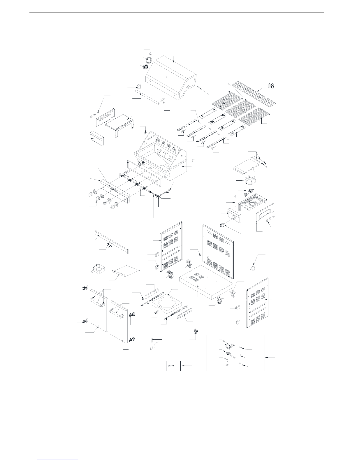
64
72
71
65
62
60
31
26
24
28
19
16
17
18
27
21
25
22
23
29
20
32
30
31
45
43
41
42
50
57
57
59
48
70
40
39
38
38
49
04
03
53
53
53
53
34
35
05
07
56
51
52
54
69
67
68
66
64
58
36
36
33
36
55
63
36
47
44
43
46
13
14
15
12
02
09
37
11
06
01
02
10
76b
76a
76c
76e
76f
76g
76d
76
75
75a
74
73
61
REPLACEMENT PARTS
9

Part
Number
Part (description) War
Coverage
ranty
Quantity
Part
Number
Part (description Warranty
Coverage
Quantity
01 Main lid 3 1
02 Main lid screw 1 2
03 Temperature gauge
1 1
housing
04 Temperature gauge 1 1
05
06
Main lid handle seat, left
Main lid handle tube
1 1
1 1
07 Main lid handle seat, right 1 1
08
09
10
11
12
13
14
15
16
40
41
42
43
44
45
17
18
19
20
21
22
23
24
25
26
27
28
29
30
31
32
33
34
35
36
37
38
39
Warming rack
Cooking grid with hole A 3 1
Cooking grid with hole B 3 2
Main burner 10 4
Main burner igniter wire A 1 1
Main burner igniter wire B 1 1
Main
ner igniter wire C 1 1
bur
Main burner igniter wire D 1 1
Main lid bracket, right 1 1
Main burner bowl
assembly
Main lid bracket, left
Regulator, LP
Front baffle 1 1
Igniter junction wire 1 1
Main gas valve 1
Main manifold
Side burner orifice bracket
Side burner flex gas line A
Side manifold
Side burner gas valve
Side burner flex gas line B 1 1
Logo
Main control panel 3
Control knob
Bezel
Cart frame, front
Door magnet
Grease box
Door hinge
Flame tamer 3 4
Door handle assembly 1 2
Door, left 3 1
Door, right
Lighting rod 1 1
Lighting rod cover 1 1
Gas tank tray
slide 1 2
Tank tray bol t
Gas tank tray block piece 1 1
1 1
Non-
replaceable
1 1
1 1
1 1
1 1
1 1
1 1
1 5
1 4
1 1
1 2
1 1
10
1
1
1 4
3 1
1 1
46
Gas tank tray slide
1 1
bracket, left
47
48
Tank tray 1 1
Gas tank tray slide
1 1
bracket, right
49
50
51
52
53
54
55
56
57
58
59
60
1
61
62
63
64
65
4
66
67
68
69
1
1
70
71
72
73
1
74
75
75a
76
76a
76b
76c
76d
76e
76f
76g
77
78
79
Electric igniter module 1 1
Bottom panel 1 1
Swivel caster with brake 1 1
Swivel caster 1 1
Door hinge bracket 1 4
Side panel, left 1 1
Rubber grommet 1 1
Back panel 1 1
Caster 1 2
Side panel, right 1 1
Side burner control panel,
3 1
right
Side burner igniter 1 1
Burner pin assembly
Side burner
Side burner bowl
assembly
Hook
Side burner end cap
Side burner cooking grid
Side burner lid
Burner pin assembly
Side burner lid hinge rod
Side shelf front panel, left
Side shelf end cap
Side shelf, left
Eye bolt
Tank heat shield panel
Side burner NG orifice pack
Side burner NG orifice
NG Conversion kit
NG Gas Hose with
Quick Connector
assembly for NG unit
NG Regulator assembly
for NG unit
Phillips Head Screw
k
with Loc
Flat Washer
6 mm Nut Driver
Hex Wrench
1 4
1 1
1 1
1 6
1 1
1 1
1 1
1 2
1 2
3 1
1 1
1
1
1 1
1 1
1 1
Sold separately
as set with #76
Sold separately
as set with #76
Sold separately
as set with #76
Sold separately
as set with #76
Sold separately
as set with #76
Sold separately
as set with #76
Sold separately
as set with #76
6mm Wrench
Preassembly hardware
Manual
PVC cover
Sold separately
as set with #76
pack
1
1
1
1
1
1
1
1
2
2
1
1
1
1
1
1
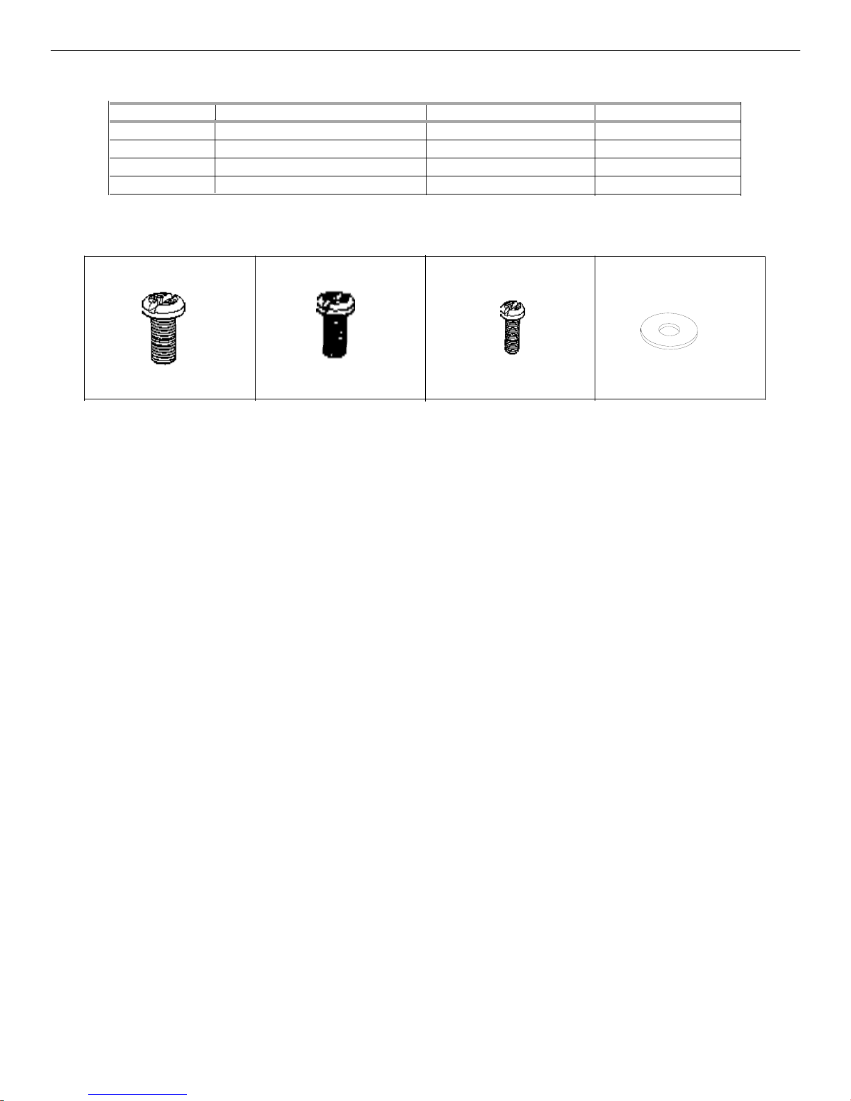
All Pre-Assembled Screws List
Sort Description Size Quantity
1 ¹⁄₄ Screw ¹⁄₄*12mm 10
2
3
4 2
1 2 3 4
⁵⁄₃₂ Screw
M4 Screw
⁵⁄₃₂ Flat washer
⁵⁄₃₂*10mm 2
M4*10mm 2
11
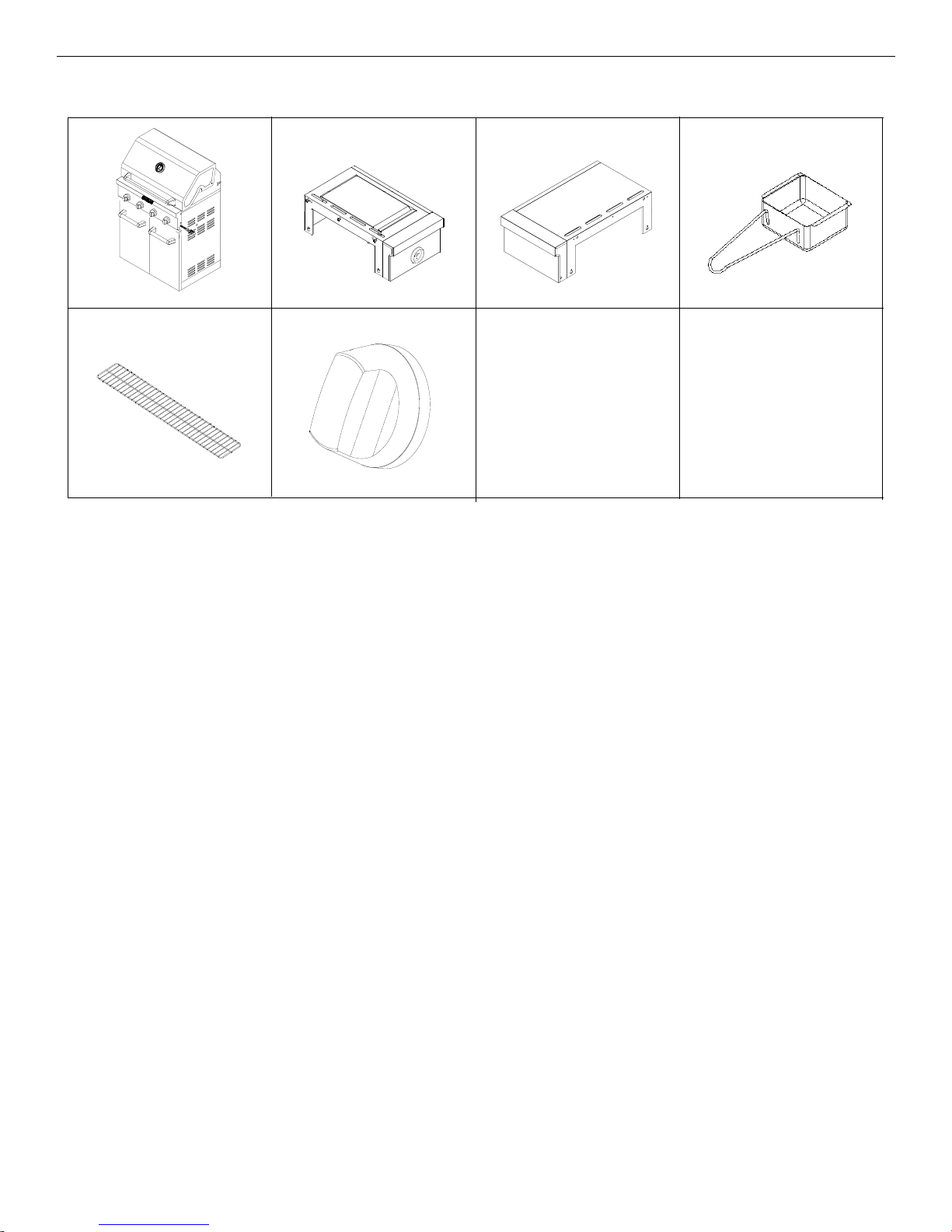
W
arming Rack
Package Content List
Si
de Burner Assembly Side Shelf Assembly
Control Knob
Grease Box
12
INST
Excessive Weight Hazard
Use two or more people to move and install grill.
WARNING
Failure to do so can result in back or other injury.
A
A
B
ALLATION INSTRUCTIONS
Freestanding Outdoor Grill Installation
Unpa
ck Grill
1. R
emove all packaging materials and remove grill from the
shipping base.
2. Move grill close to desired outdoor location.
3. Open the grill hood.
Remo
ve Packaging Material Inside the Grill
1. Use a uti
open box from top and remove the boxes.
2. Remove the warming shelf and grill grates from inside the grill
and remove the package inside the firebox.
3. Remove foam block and wrap from inside the grill.
lity knife to cut yellow straps and packing tape to
4. Remove 2 screws on grill side panel and 1 screw on grill
control panel.
A.
Grill control panel screw
B. Grill side panel screws
5.
Attach the top of the side shelf to the grill (A) by inserting the
2 screws removed in Step 3 into the side shelf from inside the
grill hood and tighten. See illustration in Step 7.
Attach the bottom of the side shelf to the side panel (B)
6.
of the grill by inserting the 2 screws removed from the grill
side panel in Step 4.
in Step 7.
7. Atta
ch the side shelf to the control panel (C) by inserting the
screw removed from the grill control panel in Step 4. Tighten
the screw.
Tighten the screws. See illustration
Att
ach Right Side Shelf with Side Burner
1. Unpack right side shelf with side burner.
2. Open grill lid.
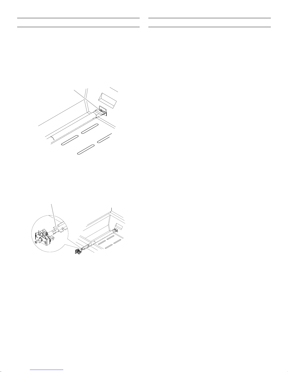
3. Remove 3 screws from the side of the side burner.
A.
Side burner screws
13
B
move the 2 screws from the side burner valve assembly.
A
B
A
A
B
Re
8.
See illustration in Step 10.
9.
Push the valve stem out through the opening in the front of
the side burner shelf, lining up the holes in the side burner
valve assembly with the openings on the side burner shelf.
See illustration in Step 10.
10. Slide the bezel opening over the valve stem and attach the
side burner valve assembly and bezel to the side burner shelf
with the screws removed in Step 8.
B
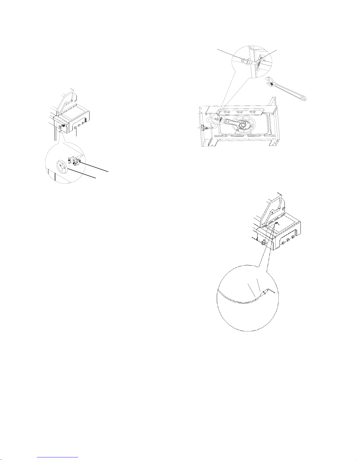
Attach side burner orifice bracket with side burner tube
11.
with preassembled brass screw, then tighten by wrench.
A. Side burner orifice bracket.
B. Side burner tube
12. Connect electrical plugs on underside of side burner.
A.
Bezel
B. Valve
A. Electrical plug from grill
B. Electrical plug from side burner
14
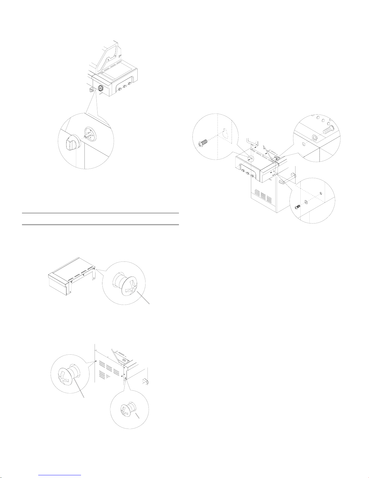
13. In
A
B
A
B
A
C
sert the valve stem into the knob and push knob into place.
14. The igniter battery is not factory installed. A “AA” size alkaline
battery is located in the accessory box on the grill grate.
Install battery at this time following the instructions in
“Replacing the Igniter Battery” section.
5. Attach the top of the side shelf to the grill (B) by inserting the
2 screws removed in Step 3 into the side shelf from inside the
grill hood and tighten. See illustration in Step 7.
6. Attach the bottom of the side shelf to the side panel (A)
of the grill by inserting the 2 screws removed from the grill
side panel in Step 4. Tighten these screws.
See illustration in Step 7.
7. Attach the side shelf to the control panel (C) by inserting the
screw removed from the grill control panel in Step 4. Tighten
the screw.
tach Left Side Shelf
At
1. Unpack left side shelf.
2. Open grill li
d.
3. Remove 3 screws from the side of the side shelf.
Side shelf screws
A.
4. Remove 2 screws on grill side panel and 1 screw
on grill control panel.
A. Grill side panel screws
B. Grill control panel screw
15
Complete Assembly
B
A
W
ARNING
Explosion Hazard
Securely tighten all gas connections.
If connected to LP, have a qualified person make sure
gas pressure does not exceed 14” (36 cm) water
column.
Examples of a qualified person include:
licensed heating personnel,
authorized gas company personnel, and
authorized service personnel.
Failure to do so can result in death, explosion, or fire.
A
place the grill grates.
1. Re
2. Place warming shelf on brackets as shown..
A.
Warming shelf brackets
B. Warming shelf
Cover your grill
Once your grill has cooled down, cover the grill between
uses. See below picture.
Make Gas Connection
NOTE: If grill i
in the “Gas Conversions” section.
0 lb LP Gas Fuel Tank
2
LP Gas:
IMPOR
separately.
IMPORTANT: The gas pressure regulator/hose assembly
supplied with the grill must be used. Replacement gas pressure
regulator/hose assembly specific to your model, is available from
your outdoor grill dealer.
Door Style Tank Tray
1. Open cabinet doors.
2. Slide the tank tray locking bracket counterclockwise 90° and
pull out the tray.
s to be converted to Natural gas, follow instructions
TANT: A 20 lb LP gas fuel tank must be purchased
A
. Tank tray locking bracket
16
3. Place th
A
C
B
A
B
e 20 lb LP gas fuel tank bottom collar into the
mounting hole in the tank tray.
4. Tighten the locking screw against the bottom collar of the
20 lb LP gas fuel tank to secure.
A.
Locking screw
B. Bottom collar
C. Mounting hole
5. Slide the tank tray with the 20 lb LP gas fuel tank back into
the cabinet and lock the locking bracket.
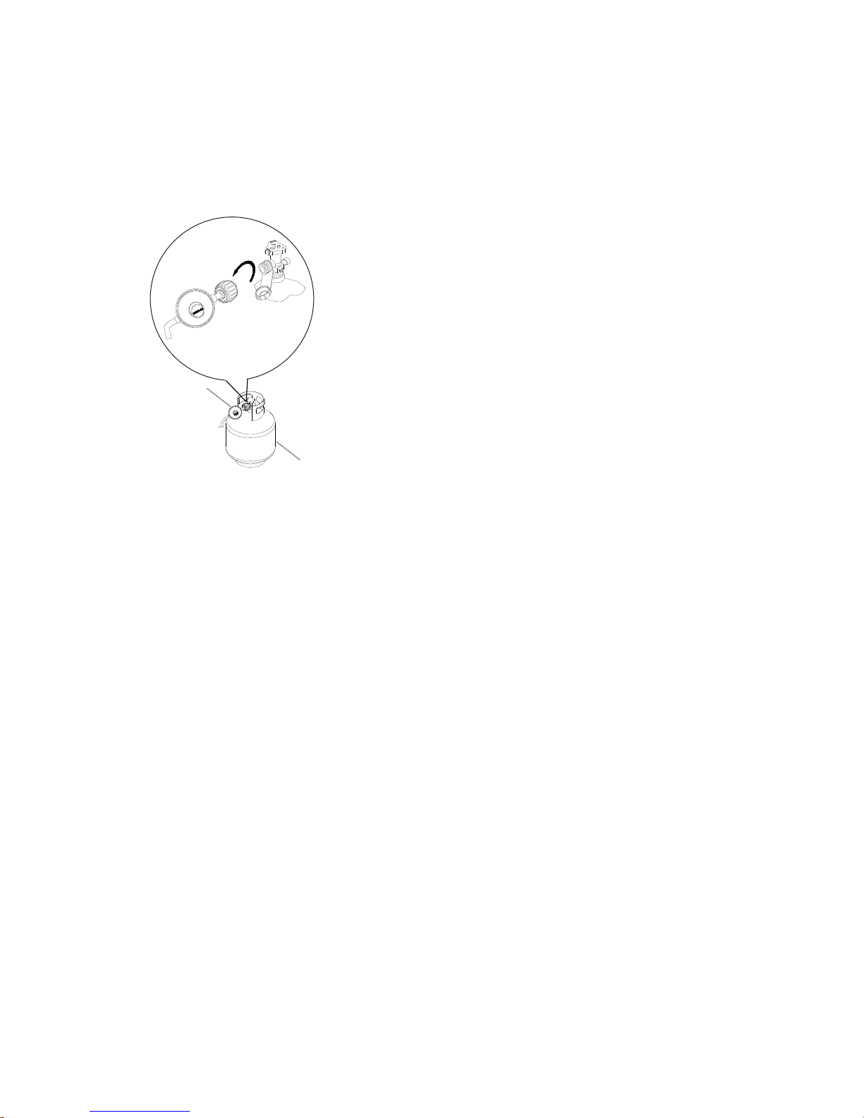
o Connect the 20 lb LP Gas Fuel Tank:
T
1. Check that the 20 lb LP gas f
uel tank is in the “Off” position. If
not, turn the valve clockwise until it stops.
2. Check that the 20 lb LP gas fuel tank valve has the proper
type-1 external male thread connections per ANSI Z21.81.
3. Check that the burner control knobs are in the “Off” position.
4. Remove any debris and inspect the valve connections, port,
and gas pressure regulator/hose assembly for damage.
NOTE: Always keep the LP cylinder at 90° (upright)
orientation to avoid vapor withdrawal.
5. Using your hand, turn the gas pressure regulator/hose
assembly clockwise to connect to the 20 lb LP gas fuel tank
as shown.
Hand tighten only. Use of a wrench could damage the quick
coupling nut.
Gas pressure regulator/hose assembly
A.
B. 20 lb LP gas fuel tank
Make sure that the cylinder valve connection device properly
mates with the connection device attached to the inlet of the
pressure regulator.
6. Open the tank valve fully by turning the valve
counterclockwise. Wait a few minutes for gas to move
through the gas line.
7. Before lighting the grill, test all connections by brushing on an
approved noncorrosive leak-detection solution. Bubbles will
show a leak.
8. If a leak is found, turn the tank valve off and do not use the
grill. Contact a qualified gas technician to make repairs.
9. Go to “Check and Adjust the Burners” section.
17
o Disconnect the 20 lb LP Gas Fuel Tank:
A
B
T
1. Check that the burner control knobs are in the “Off” position
and the grill is cool.
2. Check that the 20 lb LP gas fuel tank is in the “Off” position. If
not, turn the valve clockwise until it stops.
3. Using your hand, turn the gas pressure regulator/hose
assembly counterclockwise to disconnect to the 20 lb LP gas
fuel tank as shown.
Hand loosen only. Use of a wrench could damage the quick
coupling nut.
Gas pressure regulator/hose assembly
A.
B. 20 lb LP gas fuel tank
4. Place dust cap on cylinder valve outlet whenever the cylinder
is not in use. Only install the type of dust cap on the cylinder
valve outlet that is provided with the cylinder valve. Other
types of caps or plugs may result in leakage of propane.
18
GAS CONVERSIONS
WARNING
Explosion Hazard
Use a new CSA International approved “outdoor”
gas supply line.
Securely tighten all gas connections.
Failure to do so can result in death, explosion, or fire.
†®TE
FLON is a registered trademark of E.I. Du Pont De Nemours and Company.
Install a shut-off valve.
T
ools and Parts for Gas Conversion
G
ather the required tools and parts before starting installation.
Read and follow the instructions provided with any tools listed
here.
Tools needed
■
Phillips scr
■
Pipe wrench
■
A
djustable wrench
6 mm socket and wrench
■
ewdriver
■
Thin flat-blade scr
■
Pliers
■
Pipe
thread sealant
certified for LP gas
or 6 mm nut driver
Parts supplied
Natural gas orifices
■
ts needed
Par
Natural gas conversion kit Part Number 710-0003. See
■
“Assistance” section to order. The conversion kit includes:
■
Natural gas regulator 4" W.C. (marked “Natural Gas
Regulator”)
(3.0 m) Natural gas hose with quick connector
10 ft
■
(150 mm) Natural gas regulator hose
5.9"
■
■
6 mm nut
■
6 mm wrench
Hex key
■
IMPOR
TANT: Gas conversions must be done by a qualified
installer. Before proceeding with conversion, shut off the gas
supply to the appliance prior to disconnecting the electrical
power.
driver
ewdriver
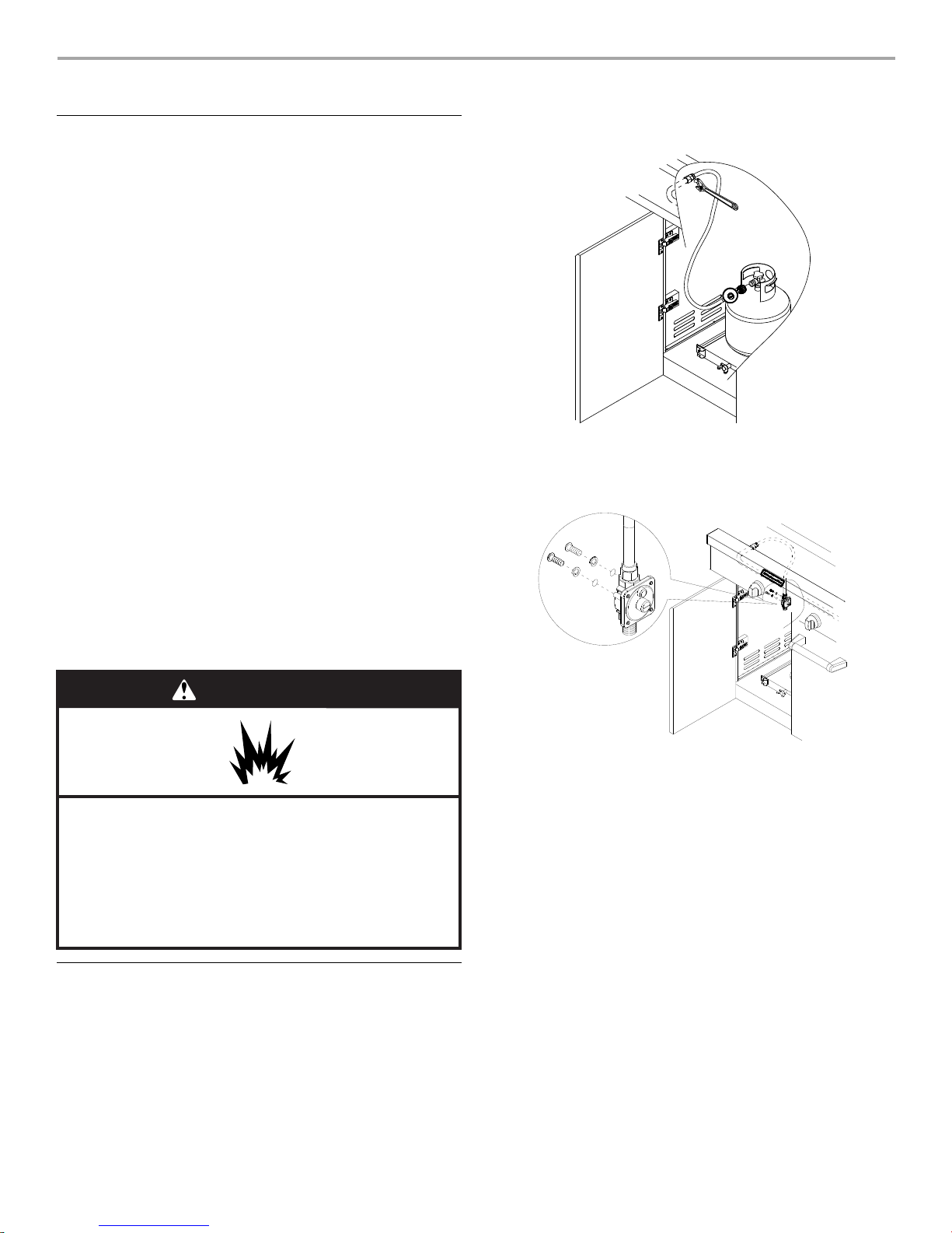
5. Use an adjustable wrench to remove the LP regulator from
the manifold.
6. Use an adjustable wrench to install the Natural gas regulator
hose to the manifold and secure. Attach the Natural gas
regulator to the side panel inside the grill cart with the two
screws that are preassembled on the regulator.
Conversion from LP Gas to Natural Gas
llation of the regulator
Insta
1. T
urn off the main gas supply valve.
2. Disconnect 20 lb LP gas fuel tank (if present).
3. Turn off all burner control valves.
4. Remove the 20 lb LP gas fuel tank (if present) from the grill
cart.
19
Mak
e Gas Connection
1. A combination of pipe fittings must be used to connect the
grill to the existing gas line.
10 ft (3.0 m) PVC flexible gas supply hose design-
The
■
certified by CSA must be used.
■
Pipe-joint comp
must be used. Do not use Teflon
■
Ther
e must be a certified manual shut-off valve in the gas
ounds suitable for use with Natural gas
®†
tape.
supply line near the grill for easy access.
2. Connect the brass connector on one end of the 10 ft (3.0 m)
PVC flexible gas supply hose to the Natural gas pressure
regulator.
3. Conne
A
B
C
D
A
A
B
ct the quick connector on the other end of the
10 ft (3.0 m) PVC flexible gas supply hose to the rigid Natural
gas supply pipe.
A.
Left side panel
B. Manifold
C. 10 ft. (3.0 m) PVC gas hose
D. Natural gas pressure regulator/hose assembly
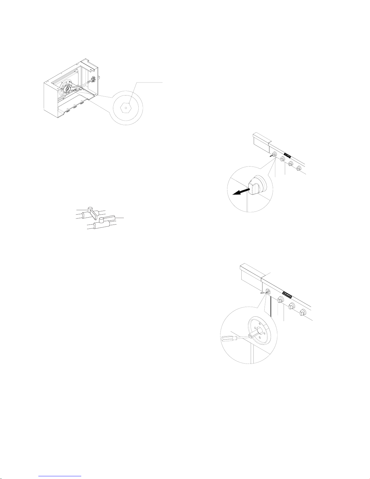
Change Grill
Burner Valve Orifices
1. Remove the grates and flame tamers.
2. Remove the 1 screw and cotter clip that hold the burner in
place. Set the screw and clip aside. Remove the burner from
the grill by lifting the burner out.
3. Use a 6 mm socket and wrench or 6 mm nut driver to remove
the brass orifice from the end of gas valve. The main burner
orifice is located behind the LP orifice, so no additional orifice
needs to be installed.
Main burner orifice
A.
IMPORTANT: Check that the orifice is properly installed
inside of the burner opening.
4. Reinsert the burner and reattach using the 2 screws
previously removed. Repeat the procedure for each main
burner.
5. Position the igniters so they are ¼" (6.0 mm) away from each
burner.
A. Screw
B. Cotter clip
20
A
A
B
Change the side burner orifice
1. Loca
2. Use 6 mm socket wrench or 6 mm nut driver to remove the
te the Liquid propane orifice at the end of the valve.
orifice. Replace with the Natural gas orifice.
cord Conversion
Re
1. The appliance nameplate is located inside the grill cabinet on
the left-hand cabinet side. With a permanent marker, check
the box next to “Natural gas” and mark through “LP Propane.”
In the last page of the Use and Care Guide, write “Converted to
Natural Gas.” Also record the conversion date and the
technician/company that performed the conversion.
NOTE: Place LP gas parts in plastic parts bag for future use and
keep with pack containing literature.
A.
Orifice
IMPORTANT: Check that the orifice is properly installed
inside of the valve.
3. Reinstall the side burner, tighten the side burner orifice
bracket and side burner tube by using a wrench.
Open the manual shutoff valve in the gas supply line. The
4.
valve is open when the handle is parallel to the gas pipe.
A. Closed valve
B. Open valve
5. Test all connections using an approved noncorrosive leak-
detection solution. Bubbles will show a leak. Correct any leak
found.
Adjust H
When
the high flame setting screw for ideal burner flame height.
1. Remove each control knob for the main burner and side
2. Use a flat-blade screwdriver to turn the high flame setscrew
igh Flame Setting Screw
converting from LP to Natural gas, you will need to adjust
burner.
counterclockwise approximate 90°.
3. Check that burner operates at the new high flame setting. It
may be necessary to adjust the screw setting slightly more to
get the ideal burner flame height.
21
Check and Adjust the Burners
1" (2.5 cm)
A
A
A
B
C
e burners are tested and factory-set for most efficient
Th
operation. However, variations in gas supply and other conditions
may make minor adjustments to air shutter or low flame setting
necessary.
It is recommended that a qualified person make burner
adjustments.
NOTE:
removing the grates and flame tamers.
The f
should be blue and stable with no excessive noise or lifting (LP
gas flames will have a slightly yellow tip). A yellow flame indicates
not enough air. If flame is noisy or lifts away from the burner, there
is too much air. Some yellow tips on flames when the burner is
set to HIGH setting are acceptable as long as no carbon or soot
deposits appear. The flames should be approximately 1" (2.5 cm)
high.
Check that burners are not blocked by dirt, debris, insect nests,
etc., and clean burners as necessary. If they are clean, adjust air
shutters as needed.
IMPORTANT: Before adjusting air shutters, let burners cool
completely.
To Adjust:
1. Light grill using information in the “Outdoor Grill Use” section.
2. Observe flame to determine which burners need adjustment
3. Turn off the valve and wait until grill and burners cool
4. Remove grill grates and flame tamers.
5. Remove the 1 screw and cotter clip that hold the burner in
Checking and adjusting the grill burner flames requires
Bur
ner Flame Characteristics
lames of the grill burners and side burners (on some models)
and how the flame is acting.
completely.
the place. Remove gas burner from the grill.
6. If flame is yellow (not enough air), turn air shutter adjustment
screw counterclockwise.
If flame is noisy or lifts away from burner (too much air), turn
air shutter adjustment screw clockwise.
Air shutter adjustment screw
A.
Adjustment should be made clockwise or counterclockwise
from ¹⁄₈" (3.2 mm) to ¹⁄₄" (6.4 mm).
7. Replace gas burner, flame tamers and grates.
8. Light grill using information in the “Outdoor Grill Use” section.
See “Burner Flame Characteristics.”
Low Flame
If flame goes out on the “LOW” setting, the low flame setting
must be adjusted.
1. Turn off the valve and wait until grill and burners are cool.
2. Remove grill grates and flame tamers.
3. Light grill using information in the “Outdoor Grill Use” section.
4. Turn burner to its lowest setting.
5. Remove each control knob for the main burner and side
burner.
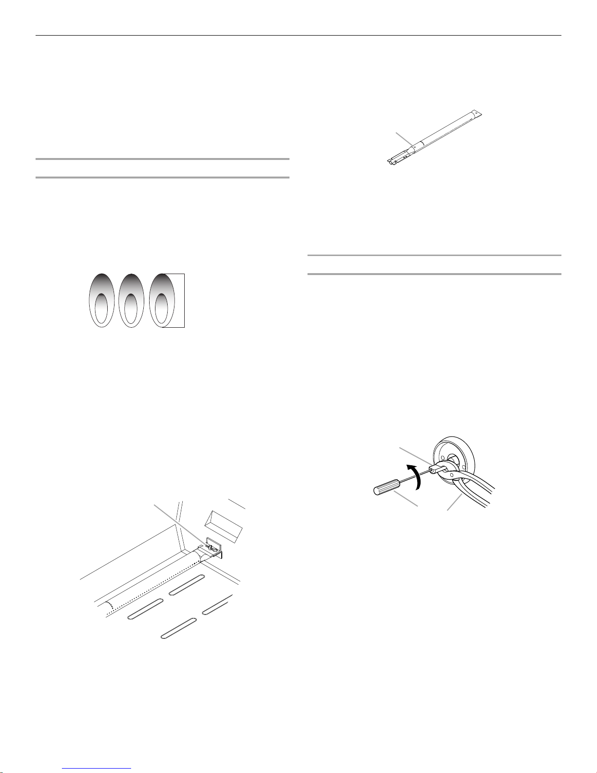
6. Hold valve stem with pliers and insert a small flat-blade
screwdriver into the shaft.
7. Watch the flame and slowly turn the screwdriver
counterclockwise.
8. Adjust flame to minimum stable flame.
Adjustment
A.
Screw
22
A. Valve stem
B. Small flat-blade screwdriver
C. Pliers
9. Replace the control knob and turn off the burner.
10. Repeat steps 3 through 9 for each burner if needed.
11. Replace the flame tamers and grates after the burners have
cooled.
OUTDOOR GRILL USE
E
D
C
BA
W
ARNING
Explosion Hazar
d
Do not store fuel tank in a garage or indoors.
Do not store grill with fuel tank in a garage or indoors.
Failure to follow these instructions can result in death,
explosion, or fire.
W
ARNING
Fire Hazard
Do not use grill near combustible materials.
Do not store combustible materials near grill.
Doing so can result in death or fire.
W
ARNING
Food Poisoning Hazard
Do not let food sit for more than one hour before or
after cooking.
Doing so can result in food poisoning or sickness.
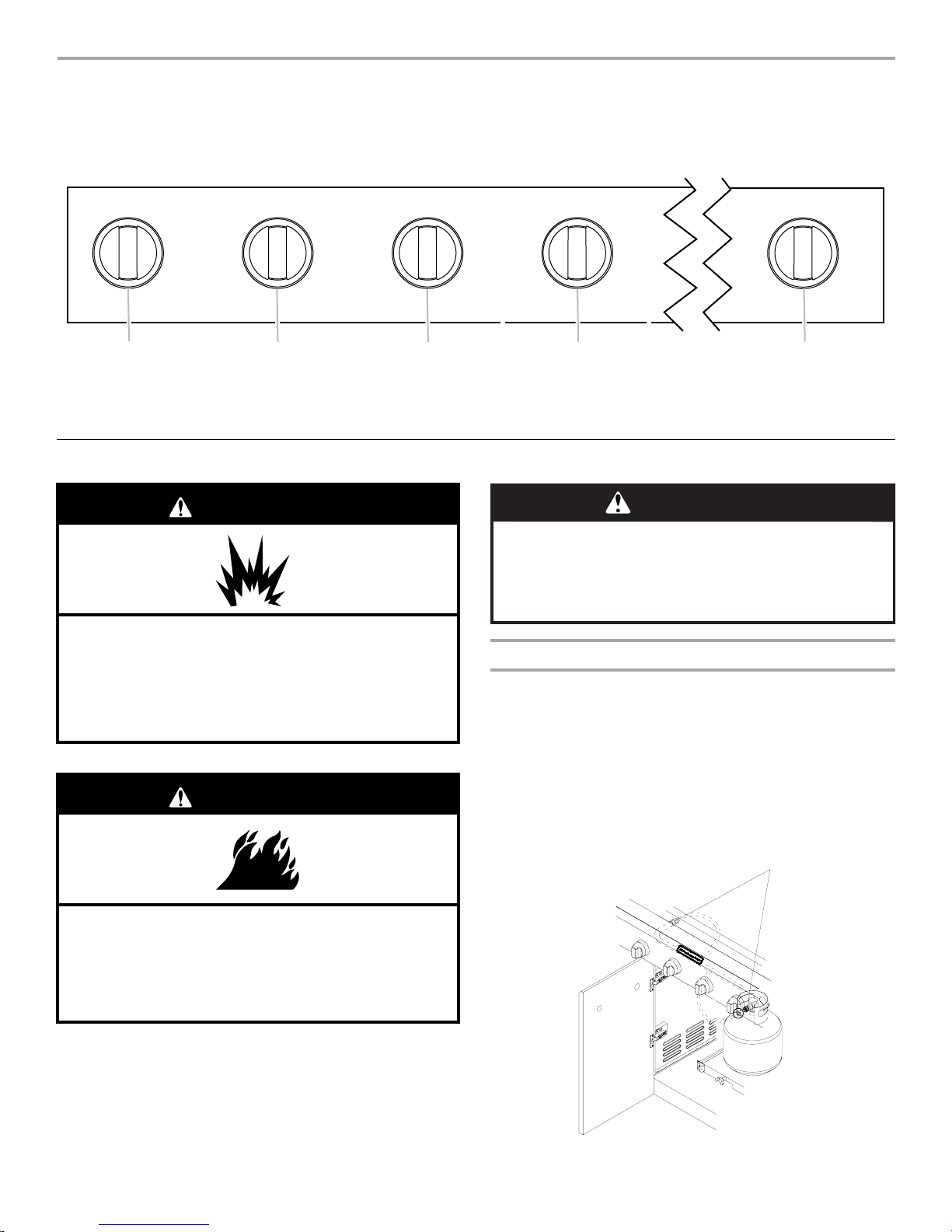
A
This manual covers several different models. The grill you have purchased may have some or all of the features listed. The locations and
appearances of the features shown here may not match those of your model.
rol Panel
Cont
Left grill burner knob
A.
B. Left-center grill burner knob
C. Right-center grill burner knob
D. Right grill burner knob
E. Side burner knob
Using Y
our Outdoor Grill
Inspec
Inspect
use.
1. Open left-hand cabinet door.
2. Inspect the gas pressure regulator/hose assembly for cuts,
3. If necessary, replace the gas pressure regulator/hose
t the LP Gas Fuel Tank Supply Hose
the gas pressure regulator/hose assembly before each
abrasions, or excessive wear.
assembly before using the grill.
Contact the dealer and use only replacement hoses specified
for use with the grill.
Gas pressure regulator/hose assembly
A.
23
Pr
A
A
B
epare the Grill for Lighting
en the hood completely. Do not light burners with the hood
1. Op
closed.
2. Make sure control knobs are turned to OFF. The drip pan
must be in place and pushed all the way to the back.
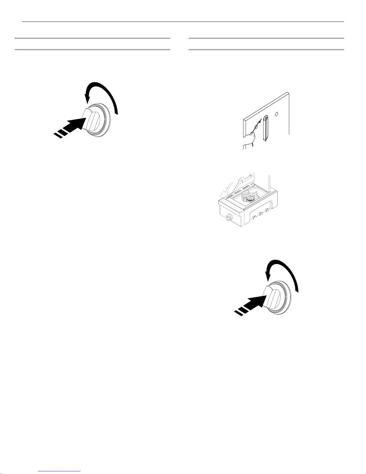
4. You will hear the “snapping” sound of the spark. When burner
is lit, release the knob. Turn knob to desired setting.
5. Repeat for each of the other burners as needed.
Manually Lighting
1. Open
2. Do not lean over the grill.
3. Remove the manual lighting extension (see following
the hood completely. Do not light burners with the hood
closed.
illustration) and attach a match to the split ring.
the Grill Burners
A.
Drip pan
urn the Gas Supply On
T
1. For
2. For outdoor grills using gas supply source other than 20 lb LP
IMPOR
burner knob to OFF and wait 5 minutes before relighting.
1. Open the hood completely. Do not light burners with the hood
2. Do not lean over the grill.
3. Select the burner you want to light. Push in and turn the grill
outdoor grills using a 20 lb LP gas fuel tank:
Slowly open the tank valve.
NOTE: If flow limiting device activates, your grill may not
light. If your grill does light, the flames will be low and will not
heat properly. Turn tank valve and all control knobs off and
wait 30 seconds. After shutting off the tank, very slowly open
tank valve and wait 5 seconds before lighting.
gas fuel tank:
Open the manual shutoff valve in the gas supply line. The
valve is open when the handle is parallel to the gas pipe.
A. Closed valve
B. Open valve
Lighting
closed.
burner control knob to IGNITE HIGH, while continuing to hold
it in.
the Grill Burners
TANT: If burner does not light immediately, turn the
4. Strike the match to light it.
5. Guide the lit match under the grill grate.
6. Push in and turn the burner knob to IGNITE HIGH for the
burner closest to the lit match. The burner will light
immediately. When burner is lit, turn knob to desired setting.
7. Repeat steps 2 through 6 for each main burner.
8. Remove match and replace manual lighting extension on the
right side panel.
IMPORTANT:
If burner does not light immediately, turn the burner knob to OFF
and wait 5 minutes before relighting.
If any burners do not light after attempting to light them manually,
contact the Customer Service Center. See the “Assistance”
section.
24
Using Y
our Side Burner
Lighting the side burner
1. Open the side burner lid. Do not light burners with the lid on.
2. Do not lean over the
3. Push in and turn the control knob to IGNITE HIGH and hold in.
While continuing to hold it in.
IMPORTANT: If burner does not light immediately, turn the
burner knob to OFF and wait 5 minutes before relighting.
grill.
ually Lighting the Side Burner
Man
1. Open the
the cover on.
2. Do not lean over the grill.
3. Remove the manual lighting extension (see the following
illustration) and attach a match to the split ring.
4. Strike the match to light it.
5. Hold the lit match close to the side burner.
side burner cover. Do not light burners with
6. Push in and turn the burner knob to IGNITE HIGH for the burner
closest to the lit match. The burner will light immediately.
When burner is lit, turn knob to desired setting.
7. Repeat steps 3 through 6 for each burner.
8. Remove match and replace manual lighting extension on the
right side panel.
IMPORTANT:
If burner does not light immediately, turn the burner knob to OFF
and wait 5 minutes before relighting.
If any burners do not light after attempting to light them manually,
contact the Customer Service Center. See the “Assistance”
section.
25
IPS FOR OUTDOOR
W
ARNING
Food Poisoning Hazard
Do not let food sit for more than one hour before or
after cooking.
Doing so can result in food poisoning or sickness.
T
GRILLING
Befor
e Grilling
■
Thaw food items befor
eheat grill on high (use all grill burners) 10 minutes. The
Pr
■
hood must be closed during preheating.
provides the high heat needed to brown and seal the juices.
Shorten the
■
or poultry, such as chicken thighs. This will help reduce
flare-ups.
ghtly oil the grill grates or the food when cooking low-fat
Li
■
cuts of meat, fish or poultry, such as lean hamburger patties,
shrimp or skinless chicken breasts.
Using too
■
rim excess fat from meats prior to cooking to reduce
T
■
flare-ups.
ake vertical cuts at 2" (5 cm) intervals around the fat edge
M
■
of meat to avoid curling.
Add seasoni
■
preheat time when grilling high-fat cuts of meat
much oil can cause gray ash to deposit on food.
ng or salt only after the cooking is finished.
e grilling.
Preheating
During Grilling
■
T
urn foods only once. Juices are lost when meat is turned
several times.
■
T
urn meat just when juices begin to appear on the surface.
void puncturing or cutting the meats to test doneness. This
A
■
allows juices to escape.
It
■
may be necessary to lower the heat setting for foods that
cook a long time or are marinated or basted in a sugary
sauce.
If using
■
10 minutes of cooking to avoid burning the sauce.
The
■
of meat (size, shape and thickness), heat setting selected,
and length of time on the grill.
Cooking time
■
a high flame, add barbecue sauce only during the last
degree of doneness is influenced by the type of meat, cut
will be longer with an open grill cover.
26

Cooking Methods
Dir
ect Heat
Cooking by
directly above lighted burners. Hood position can be up or down.
If hood is in the up position, total cooking times may be longer.
Direct heat sears the food. Searing is a process that seals natural
juices in food by cooking with intense heat for a short period of
time. While juices stay inside, the outside is browned with a
flavorful grilled coating.
direct heat means the food is placed on grill grates
Grilling Chart
■
Knobs
have High, Medium and Low settings for flame
adjustment.
■
Hea
t settings indicated are approximate.
lling times are affected by weather conditions.
Gri
■
Indir
ect Heat
For best r
when it is windy.
Cooking by indirect heat means the food is placed on the grill
grate above an unheated burner, allowing heat from lighted
burner(s) on either side to cook the food.
If possible, turn on 2 burners. Cook with the hood down. This will
shorten the cooking time.
■
■
esults, do not select the indirect heat cooking method
When
2 temperatures are listed, for example: Medium to
Medium-Low, start with the first and adjust based on cooking
progress.
Cooking times
type of fuel, Natural or LP gas.
may vary from chart times depending on the
FOOD COOKING METHOD/
BURNER SETTING
Beef
Hamburgers ½" (1.3 cm) to
¾" (1.9 cm) thick
Roasts
Rib Eye, Sirloin
Steaks, 1" (2.5 cm)
Porterhouse, Rib, T-bone,
Top Lo i n, Si r loin
Steaks, 1½" (3.8 cm)
Porterhouse, Rib, T-bone,
Top Lo i n, Si r loin
Top Round or Shoulder/
Chuck (London Broil)
1½" (3.8 cm) thick
Flank, ½" (1.3 cm) thick
Pork
Chops,
1" (2.5 cm)
1½" (3.8 cm) thick
Ribs
2½-4 lbs (0.9-1.5 kg)
Roast, boneless tenderloin,
1 lb (0.37 kg)
Ham half,
8-10 lbs (3-3.7 kg)
DIRECT
Medium
INDIRECT
Medium/OFF/Medium
DIRECT
Medium
DIRECT
Medium
DIRECT
Medium
DIRECT
Medium
DIRECT
Medium to Med-Low
INDIRECT
Med/OFF/Med
DIRECT
Medium
INDIRECT
Med/OFF/Med
INTERNAL TEMP. TIME
(total minutes)
Medium (160°F/71°C)
Med-Rare (145°F/63°C)
to Medium (160°F/71°C)
Med-Rare (145°F/63°C)
to Medium (160°F/71°C)
Med-Rare (145°F/63°C)
to Medium (160°F/71°C)
Med-Rare (145°F/63°C)
to Medium (160°F/71°C)
Med-Rare (145°F/63°C)
Medium (160°F/71°C)
Mediu
m (160°F/71°C)
Medium (160°F/71°C)
Reheat (140°F/60°C)
10-15
32-40 per lb
(15-18 per kg)
11-16
18-25
22-29
11-16
12-22
30-40
40-60
18-22
2-2½ hours
SPECIAL INSTRUCTIONS
Grill, turning once.
Tent with foil first 45-60 minutes
of cooking time.
Rotate steaks ¼ turn to create
criss-cross grill marks.
Grill, turning occasionally.
During last few minutes, brush
with barbecue sauce if desired.
When done, wrap in foil.
Turn during cooking to brown
on all sides.
Wrap entire ham in foil and put
on grill without pan or drip pan.
Ham steak precooked,
½" (1.3 cm) thick
Hot Dogs
Chicken
Breast, boneless
Pieces, 2-3 lbs
(0.75-1.1 kg)
DIRECT
Preheat Medium
Grill Medium
DIRECT
Medium
DIRECT
Medium
DIRECT
Med-Low to Medium
27
Reheat (145°F/63°C)
Reheat (145°F/63°C)
170°F/77°C
Breast 170°F/77°C
Thigh 180°F/82°C
7-10
5-10
15-22 For even cooking, pound breast
Slit skin if desired.
to ¾" (2.0 cm) thick.
Start bone side down.

FOOD COOKING METHOD/
BURNER SETTING
Lamb
Ch
ops and Steaks,
Loin, Rib, Sirloin
1" (2.5 cm) thick
DIRECT
Medium
1½" (3.8 cm) thick
DIRECT
Medium
Fish and Seafood
INTERNAL TEMP. TIME
(total minutes)
Med-rare (145°F/63°C)
10-20
to Medium (160°F/71°C)
Med-rare (145°F/63°C)
16-20
to Medium (160°F/71°C)
SPECIAL INSTRUCTIONS
Fillets, Steaks, Chunks
Halibut, Salmon,
Swordfish, 8 oz (0.25 kg)
Whole, Catfish, Rainbow
Trout, 8-11 oz
(0.25-0.34 kg)
Shellfish, Scallops, Shrimp
Turkey
Whole breast (bone-in)
Half breast (bone-in)
Whole,
7-12 lbs (2.6-5.4 kg)
Fresh Vegetables
Corn on the cob
Eggplant
Onion,
½" (1.3 cm) thick
Potatoes,
Sweet, whole
Baking, whole
Peppers,
Roasted
Squash,
Summer, Zucchini
Garlic
Roasted
DIRECT
Medium
DIRECT
High
DIRECT
Medium
INDIRECT
High/OFF/High
INDIRECT
Medium/OFF/Medium
INDIRECT
High/OFF/High
DIRECT
Medium
DIRECT
Medium
DIR
ECT
Medium
DIRECT
Medium
DIRECT
High
DIRECT
High
DIRECT
Medium
DIRECT
Medium
170°F/77°C
170°F/77°C
Breast 170°F/77°C
Thigh 180°F/82°C
4-6 per
½" (1.3 cm)
thickness of fish
5-7 per side
4-8
14-18 per lb
(7-8 per kg)
25-30 per lb
(11-14 per kg)
11-16 per lb
(5-7 per kg)
20-25
7-10
8-20
40-70
45-90
15-22
7-10
20-25
Grill, turning once. Brush grill
with oil to keep fish from
sticking. Remove when inside is
opaque and flaky with skin
easily removed.
Tent with foil until last
30 minutes of cooking time.
Start skin side down.
Less than 11 lbs (5.0 kg)
Soak in cold water 20 minutes.
Do not husk. Shake off excess
water.
Wash and cut into ½" (1.3 cm)
slices or lengthwise. Brush with
olive oil.
Grill, turning once. Brush with
olive oil. Put a skewer through
several slices to hold together.
Individually wrap in heavy-duty
foil. Grill, rotating occasionally.
Wash and place on grill whole.
Char skin all around. Cool in a
paper bag or plastic wrap to
loosen blackened skin. Peel
and remove seeds.
Wash and cut into ½" (1.3 cm)
slices or lengthwise. Brush with
olive oil.
Cut off top, drizzle with olive oil
and wrap in double layer of foil.
28
OUTDOOR GRILL CARE
A
B
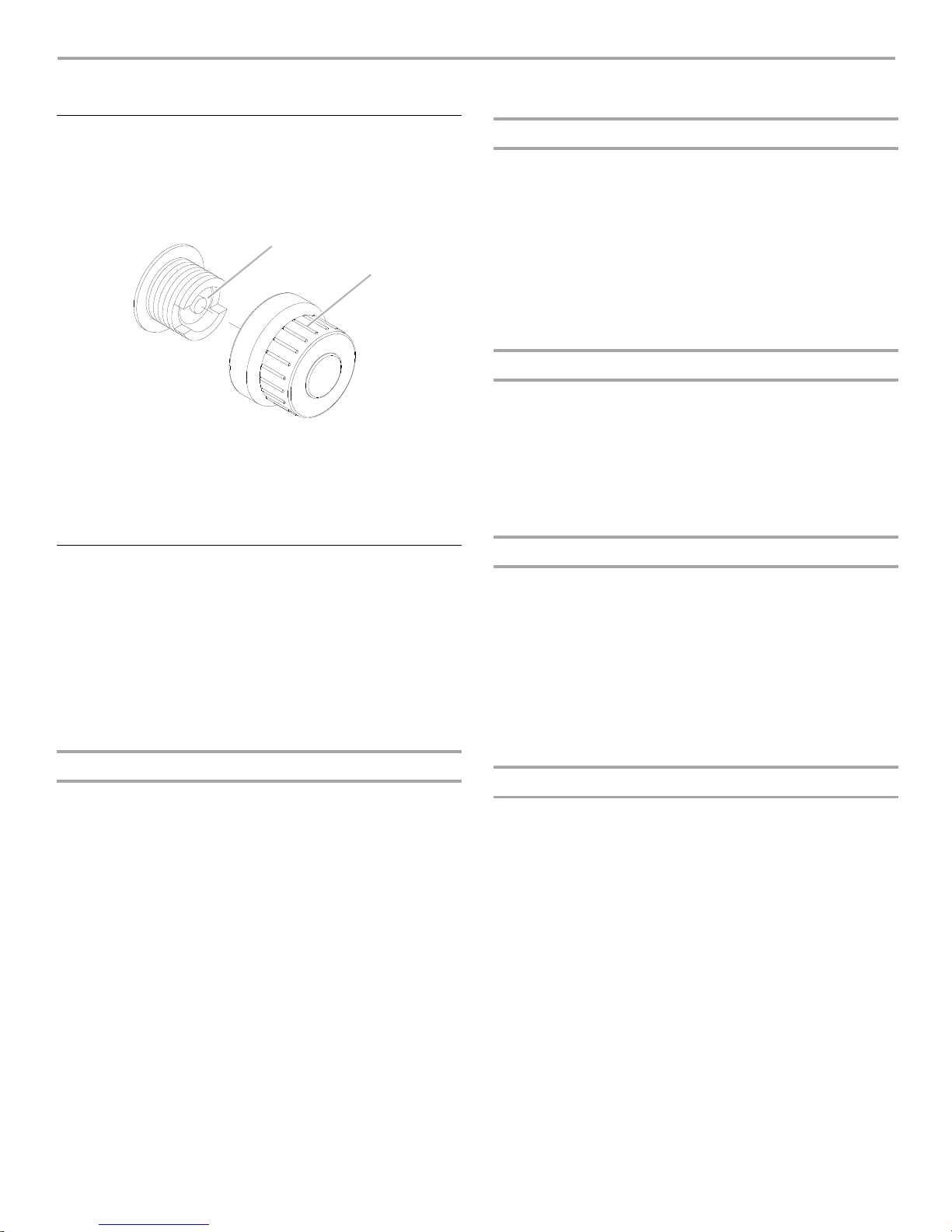
Replacing the Igniter Battery
If igniters
1. The igniter button cap is located on the outside of the grill’s
2. Unscrew igniter button cap counterclockwise to remove.
3. Remove battery from the battery compartment.
4. Replace with a new alkaline “AA” size battery. Install battery
5. Screw igniter button cap clockwise into place.
stop sparking, the battery should be replaced.
right side panel.
“AA” size battery
A.
B. Igniter cap
with negative end in first.
General Cleaning
IMPOR
the grill is cool. Always follow label instructions on cleaning
products.
For routine cleaning, wash with soap and water using a soft cloth
or sponge. Rinse with clean water and dry at once with a soft,
lint-free cloth to avoid spots and streaks.
Do not use steel wool to clean the grill, as it will scratch the
surface.
To avoid weather damage to finish, use vinyl grill cover.
IMPOR
use soap-filled scouring pads, abrasive cleaners, cooktop
polishing creme, steel wool, gritty washcloths or paper towels.
Cleaners should not contain chlorine. Damage may occur.
Food spills should be cleaned as soon as entire grill is cool. Spills
may cause permanent discoloration.
Clea
■
■
■
■
■
■
TANT: Before cleaning, make sure all controls are off and
AINLESS STEEL
ST
TANT: To avoid damage to stainless steel surfaces, do not
ning Method:
Ru
b in direction of grain to avoid scratching or damaging the
surface.
Stai
nless steel cleaner.
d detergent or all-purpose cleaner.
Liqui
nse with clean water and dry with soft, lint-free cloth.
Ri
V
inegar to remove hard water spots.
lass cleaner to remove fingerprints.
G
GRILL GRATES
IMPOR
or fiber scraper. Immediately after you are finished cooking,
loosen food soil with a brass bristle brush. Turn all burners to
HIGH for 10-15 minutes with the hood closed to burn off food
soil. Turn off all burners, raise the hood and let grates cool. Use
the brass bristle brush to remove ash from the grill grates.
When completely cool, grill racks can be removed for thorough
cleaning. Clean them with a mild detergent and warm water.
For baked-on soil, prepare a solution of 1 cup (250 mL) ammonia
to 1 gal. (3.75 L) water. Soak grates for 20 minutes, then rinse
with water and dry completely.
TANT: To avoid damage to grill grates, do not use a steel
WA
RMING SHELF
Cleaning Method:
iquid detergent or an all-purpose cleaner.
L
■
inse with clean water and dry with soft, lint-free cloth.
R
■
For t
■
ough spots or baked-on grease, use a commercial
degreaser.
IMPORTANT: Make sure gas supply is off and all control knobs
are in the Off position.
EXTERIOR
The
quality of this material resists most stains and pitting,
providing that the surface is kept clean, polished and covered.
■
Apply
stainless steel polish to all non-cooking areas before
first use. Reapply after each cleaning to avoid permanent
damage to surface.
ing should always be followed by rinsing with clean
Clean
■
warm water.
cloth.
For t
■
ough spots or baked-on grease, use a commercial
degreaser designed for stainless steel.
IN
TERIOR
D
iscoloration of stainless steel on these parts is to be expected,
due to intense heat from the burners. Always rub in the direction
of the grain. Cleaning should always be followed by rinsing with
clean, warm water.
ing Method:
Clean
quid detergent or all-purpose cleaner.
Li
■
■
Rinse with cl
free cloth.
■
A hea
products.
■
small, difficult-to-clean areas, use a commercial
For
degreaser designed for stainless steel.
W
ipe the surface completely dry with a soft
ean water and dry completely with a soft, lint-
vy-duty scrub sponge can be used with mild cleaning
29
BUR
A
A
NERS
SIDE BUR
NER
Cleaning Method:
Clean the exterior of the burner with a wire brush.
■
■
Clear any cl
ogged burner ports with a straightened paper
clip.
■
Do not use
■
Ch
eck and clean burner/venturi tubes.
a toothpick as it may break off and clog the port.
1. Remove grill grates and flame tamers.
2. Remove the 1 screw and cotter clip that hold the burner
in the place. Remove gas burner from the grill.
2 screws
A.
3. Use a flashlight to inspect into the burner through the
burner inlet to ensure there is no blockage. If any
obstruction is seen, use a metal coat hanger that has
been straightened to clear them.
4. After inspecting the inside of burner for blockage,
reassemble burner by sliding the middle tube of the gas
burner over the gas orifice.
ing Method:
Clean
Clean the exterior of the side burner with a wire brush.
■
A. Burner/orifice connection
5. Reattach gas burner using 2 screws.
30
 Loading...