

KitchenAid 720-0745A (LP), 730-0745A Installation Instructions And Use & Care Manual
FREESTANDING OUTDOOR GRILL
720-0745A (LP) 730-0745A (NG)
Installation Instructions and Use & Care Guide
For questions about features, operation/performance, parts, accessories or service, call: 1-877-373-2301
or visit our website at www.Kitchenaidgrills.com
ASADOR AUTÓNOMO PARA EXTERIOR
Instrucciones de instalación y Manual de uso y cuidado
Para consultas respecto a características, funcionamiento, rendimiento, piezas, accesorios o servicio técnico, llame al: 1-877-373-2301
o visite nuestro sitio de internet en www.Kitchenaidgrills.com
COMPTOIR POUR GRIL D'EXTÉRIEUR
AUTOPORTANT
Instructions d’installation et Guide d’utilisation et d’entretien
Pour des questions à propos des caractéristiques, du fonctionnement/rendement, des pièces, des accessoires ou du service,
composer le : 1-877-373-2301
ou visitez notre site web www.Kitchenaidgrills.com
Table of Contents/Índice/Table des matières..................................................................2
19000358AO

TABLE OF CONTENTS
OUTDOOR GRILL SAFETY............................................................3
INSTALLATION REQUIREMENTS ................................................5
Tools and Parts ............................................................................ 5
Location Requirements................................................................5
Product Dimensions ....................................................................6
Electrical Requirements ............................................................... 6
Gas Supply Requirements ...........................................................7
Gas Connection Requirements....................................................7
REPLACEMENT PARTS ................................................................9
All Pre-Assembled Screws List..................................................12
Package Content List.................................................................13
INSTALLATION INSTRUCTIONS ................................................14
Freestanding Outdoor Grill Installation ......................................14
Make Gas Connection ...............................................................17
GAS CONVERSIONS....................................................................20
Tools and Parts for Gas Conversion..........................................20
Conversion from LP Gas to Natural Gas ...................................20
Check and Adjust the Burners...................................................24
ÍNDICE
SEGURIDAD DEL ASADOR PARA EXTERIORES .....................39
REQUISITOS DE INSTALACIÓN.................................................41
Herramientas y piezas................................................................41
Requisitos de ubicación.............................................................41
Medidas del producto................................................................42
Requisitos eléctricos..................................................................42
Requisitos del suministro de gas...............................................43
Requisitos para la conexión de gas...........................................44
All Pre-Assembled Screws List..................................................48
Paquete Lista De Contenido......................................................49
INSTRUCCIONES DE INSTALACIÓN.........................................50
Instalación del asador autónomo para exteriores .....................50
Conexión del suministro de gas ................................................54
CONVERSIONES DE GAS ...........................................................56
Herramientas y piezas para la
conversión de gas......................................................................56
Conversión de gas LP a gas natural..........................................56
Revise y regule los quemadores................................................59
OUTDOOR GRILL USE ................................................................25
Using Your Outdoor Grill............................................................25
Hood Lights................................................................................26
Using Your Searing Side Burner ................................................27
Using Your Rotisserie Burner.....................................................28
Rotisserie Cooking Tips .............................................................28
TIPS FOR OUTDOOR GRILLING ................................................29
Cooking Methods.......................................................................30
Grilling Chart...............................................................................30
OUTDOOR GRILL CARE..............................................................32
Replacing the Igniter Battery......................................................32
Changing the Light Bulb.............................................................32
General Cleaning........................................................................33
TROUBLESHOOTING ..................................................................35
ASSISTANCE ................................................................................35
Accessories ................................................................................35
WARRANTY ..................................................................................36
USO DEL ASADOR PARA EXTERIORES ...................................61
Cómo usar el asador para exteriores.........................................61
Luces de la capota.....................................................................63
Cómo usar el quemador lateral para dorado rápido .................63
Cómo usar el quemador del rostizador .....................................64
Consejos para la cocción con el rostizador...............................65
CONSEJOS PARA ASAR AL AIRE LIBRE..................................66
Métodos de cocción ..................................................................66
Cuadro para asar........................................................................67
CUIDADO DEL ASADOR PARA EXTERIORES..........................69
Cómo reemplazar la batería del encendedor ............................69
Cómo cambiar el foco................................................................69
Limpieza general ........................................................................70
SOLUCIÓN DE PROBLEMAS......................................................72
ASISTENCIA..................................................................................73
Accesorios..................................................................................73
GARANTÍA....................................................................................73
SÉCURITÉ DU GRIL D'EXTÉRIEUR ...........................................76
EXIGENCES D’INSTALLATION...................................................78
Outils et pièces...........................................................................78
Exigences d'emplacement.........................................................78
Dimensions du produit...............................................................79
Spécifications électriques..........................................................79
Spécifications de l'alimentation en gaz .....................................80
Exigences concernant le raccordement au gaz ........................81
PIÈCES DE RECHANGE ..............................................................82
All Pre-Assembled Screws List..................................................85
Package Content List.................................................................86
INSTRUCTIONS D'INSTALLATION ............................................87
Installation du gril d’extérieur autoportant.................................87
Raccordement au gaz................................................................90
CONVERSIONS POUR CHANGEMENT DE GAZ ......................92
Outils et pièces pour conversion de gaz ...................................92
Conversion de propane à gaz naturel........................................93
Contrôle et réglage des brûleurs ...............................................96
2
TABLE DES MATIÈRES
UTILISATION DU GRIL D’EXTÉRIEUR.......................................97
Utilisation du gril d’extérieur.......................................................98
Lampes sous le couvercle..........................................................99
Utilisation du brûleur à rôtissage latéral.....................................99
Utilisation du brûleur de tournebroche ....................................101
Conseils de cuisson à l’aide du tournebroche ........................101
CONSEILS POUR L'UTILISATION DU GRIL D'EXTÉRIEUR ..103
Méthodes de cuisson...............................................................103
Tableau de cuisson au gril .......................................................104
ENTRETIEN DU GRIL D’EXTÉRIEUR .......................................107
Remplacement de la pile de l’allumeur....................................107
Changement de l’ampoule d’éclairage....................................107
Nettoyage général ....................................................................108
DÉPANNAGE...............................................................................110
ASSISTANCE ..............................................................................110
Accessoires ..............................................................................110
GARANTIE...................................................................................111
OUTDOOR GRILL SAFETY
You can be killed or seriously injured if you don't immediately
You
can be killed or seriously injured if you don't
follow
All safety messages will tell you what the potential hazard is, tell you how to reduce the chance of injury, and tell you what can
happen if the instructions are not followed.
Your safety and the safety of others are very important.
We have provided many important safety messages in this manual and on your appliance. Always read and obey all safety
messages.
This is the safety alert symbol.
This symbol alerts you to potential hazards that can kill or hurt you and others.
All safety messages will follow the safety alert symbol and either the word “DANGER” or “WARNING.”
These words mean:
follow instructions.
instructions.
DANGER
WARNING
If you smell gas:
1. Shut off gas to the appliance.
2. Extinguish any open flame.
3. Open lid.
4. If odor continues, keep away from the
appliance and immediately call your
gas supplier or your fire department.
DANGER
WARNING
1. Do not store or use gasoline or other
flammable liquids or vapors in the
vicinity of this or any other appliance.
2. An LP cylinder not connected for use
shall not be stored in the vicinity of
this or any other appliance.
State of California Proposition 65 Warnings:
WARNING: This product contains one or more chemicals known to the State of California to cause cancer.
WARNING: This product contains one or more chemicals known to the State of California to cause birth defects or other
reproductive harm.
In the State of Massachusetts, the following installation instructions apply:
■
Installations and repairs must be performed by a qualified or licensed contractor, plumber, or gasfitter qualified or licensed by
the State of Massachusetts.
■
If using a ball valve, it shall be a T-handle type.
■
A flexible gas connector, when used, must not exceed 3 feet.
IMPORTANT: This grill is manufactured for outdoor use only. For grills that are to be used at elevations above 2000 ft (609.6 m) orifice
conversion is required. See “Gas Supply Requirements” section. It is the responsibility of the installer to comply with the minimum
installation clearances specified on the model/serial rating plate. The model/serial rating plate for freestanding models can be found
inside left-hand cabinet door.
3
SAVE THESE INSTRUCTIONS
IMPORTANT SAFETY INSTRUCTIONS
WARNING: To reduce the risk of fire, electrical shock,
injury to persons, or damage when using the outdoor cooking
gas appliance, follow basic precautions, including the
following:
■ Do not install portable or built-in outdoor cooking gas
appliances in or on a recreational vehicle, portable trailer,
boat or in any other moving installation.
■ Always maintain minimum clearances from combustible
construction, see “Location Requirements” section.
■ The outdoor cooking gas appliance shall not be located
under overhead unprotected combustible construction.
■ This outdoor cooking gas appliance shall be used only
outdoors and shall not be used in a building, garage, or any
other enclosed area.
■ Keep any electrical supply cord and fuel supply hose away
from any heated surfaces.
■ Keep outdoor cooking gas appliance area clear and free
from combustible materials, gasoline and other flammable
vapors and liquids.
■ Do not obstruct the flow of combustion and ventilation air.
Keep the ventilation openings of the cylinder enclosure free
and clear from debris.
■ Open the cabinet door and inspect the gas cylinder supply
hose before each use of the outdoor cooking gas
appliance. If the hose shows excessive abrasion or wear,
or is cut, it MUST be replaced before using the outdoor
cooking gas appliance. Contact your dealer and use only
replacement hoses specified for use with the outdoor
cooking gas appliance.
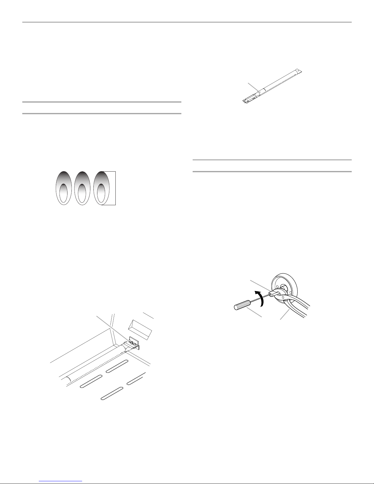
■ Visually check the burner flames.
They should be blue. Slight
yellow tipping is normal for LP
gas. The flames should be
approximately 1" (2.5 cm) high.
■ Check and clean burner/venturi tube for insects and insect
nest. A clogged tube can lead to fire under the outdoor
cooking gas appliance.
■ The LP gas supply cylinder to be used must be:
- constructed and marked in accordance with the
Specification for LP Gas Cylinders of the U.S. Department
of Transportation (DOT) or the National Standard of
Canada, CAN/CSA-B339, Cylinders, Spheres, and Tubes
for Transportation of Dangerous Goods; and Commission.
- provided with a listed overfilling prevention device.
- provided with a cylinder connection device compatible
with the connection for outdoor cooking gas appliances.
■ Always check connections for leaks each time you connect
and disconnect the LP gas supply cylinder. See
“Installation Instructions” section.
■ When the outdoor cooking gas appliance is not in use, the
gas must be turned off at the supply cylinder.
■ Storage of an outdoor cooking gas appliance indoors is
permissible only if the cylinder is disconnected and
removed from the outdoor cooking gas appliance.
■ Cylinders must be stored outdoors and out of the reach of
children and must not be stored in a building, garage, or
any other enclosed area.
■ The pressure regulator and hose assembly supplied with
the outdoor cooking gas appliance must be used. A
replacement pressure regulator and hose assembly
specific to your model is available from your outdoor
cooking gas appliance dealer.
■ Gas cylinder must include a collar to protect the cylinder
valve.
■ For appliances designed to use a CGA791 Connection:
Place a dust cap on cylinder valve outlet whenever the
cylinder is not in use. Only install the type of dust cap on
the cylinder valve outlet that is provided with the cylinder
valve. Other types of caps or plugs may result in leakage
of propane.
If the following information is not followed exactly, a fire
causing death or serious injury may occur.
■ Do not store a spare LP gas cylinder under or near this
outdoor cooking gas appliance.
■ Never fill the cylinder beyond 80 percent full.
1"
(2.5 cm)
4
INSTALLATION REQUIREMENTS
WARNING
Explosion Hazard
Do not store fuel tank in a garage or indoors.
Do not store grill with fuel tank in a garage or indoors.
Failure to follow these instructions can result in death,
explosion, or fire.
WARNING
Fire Hazard
Do not use grill near combustible materials.
Do not store combustible materials near grill.
Doing so can result in death or fire.
Tools and Parts
Gather the required tools and parts before starting installation.
Read and follow the instructions provided with any tools listed
here.
Tools Needed
■ Phillips screwdriver
■ Wrench or pliers
■ Pipe wrench
Parts Supplied
■ Gas pressure regulator/hose assembly set for 11" WCP LP
gas
■ Right side shelf with sear burner
■ Left side shelf
■ Side shelf push bar
■ Side shelf push bar seat (2)
■ Searing side burner control knob
■ “AA” Batteries (3)
■ Warming rack
■ Cooking grid
■ Side burner cooking grid
■ Natural gas orifice for rotisserie/infrared burner
■ Scissors or cutting pliers
(to remove tiedowns)
■ Noncorrosive leak-
detection solution
Location Requirements
Parts Needed
■ 20 lb LP gas fuel tank - approximately 18" (45.7 cm) height
Parts Needed for Conversion to Natural Gas
■ Natural gas conversion kit Part Number 710-0003. See
“Assistance” section to order. The conversion kit includes:
■ Natural gas regulator 4" W.C. (marked “Natural Gas
Regulator”)
■ 10 ft (3.0 m) Natural gas hose with quick connector
■ 5.9" (150 mm) Natural gas regulator hose
■ 6 mm nut driver
■ 6 mm wrench
■ Hex key
■ Gas line shutoff valve
■ ½" male pipe thread nipple for connection to pressure
regulator.
■ LP gas-resistant pipe-joint compound
■ CSA design-certified outdoor flexible stainless steel
appliance connector (4-5 ft [1.2-1.5 m]) or rigid gas supply
line as needed.
Select a location that provides minimum exposure to wind and
traffic paths. The location should be away from strong draft
areas.
Do not obstruct flow of combustion and ventilation air.
Clearance to combustible construction for freestanding outdoor
grills:
■ A minimum of 24" (61 cm) must be maintained between the
front of the grill hood, sides and back of the grill and any
combustible construction.
■ A 24" (61 cm) minimum clearance must also be maintained
below the cooking surface, and the grill shall not be used
under overhead combustible construction.
Rotisserie (accessory)*
If you equip your grill with a rotisserie, a 6" (15.2 cm) minimum
clearance is needed for the rotisserie motor.
A grounded, 3-prong outlet located to the left of the grill is
required.
*See “Assistance” section to order.
5
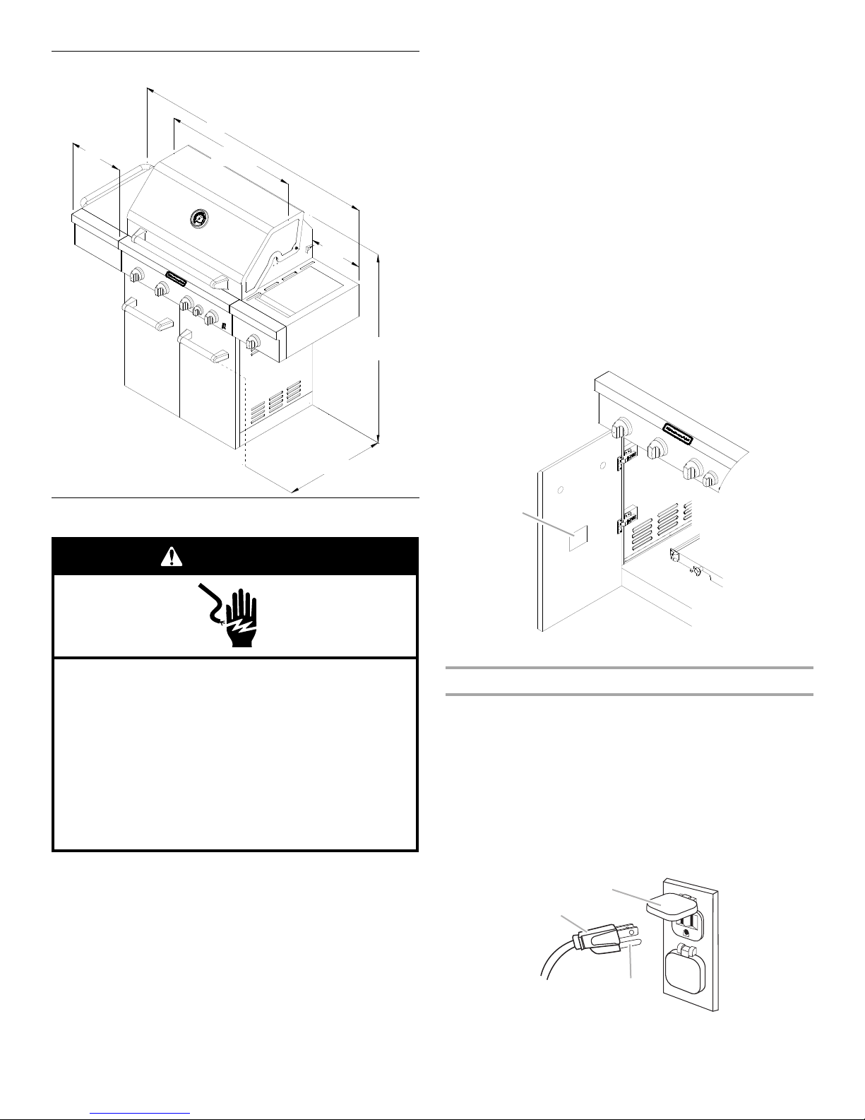
Product Dimensions
31"
(78.7 cm)
23"
(58.4 cm)
60¹⁄₄"
(153.0 cm)
12⁵⁄₈"
(32 cm)
12⁵⁄₈"
(32 cm)
48⁵⁄₈"
(123.5 cm)
Electrical Shock Hazard
Use only a UL listed, 14 gauge, 3 wire extension cord
approved for outdoor use, marked W-A, with a
maximum length of 50 ft.
Plug into a grounded 3 prong outlet.
Do not remove ground prong.
Do not use an adapter.
Failure to follow these instructions can result in death,
fire, or electrical shock.
WARNING
A
A
B
C
■ Do not operate any outdoor cooking gas appliance with a
damaged cord, damaged plug, or after the appliance
malfunctions or has been damaged in any manner. Contact
the manufacturer for repair.
■ Do not let the cord hang over the edge of a table or touch hot
surfaces.
■ Do not use an outdoor cooking appliance for purposes other
than intended.
■ When connecting, first connect plug to the outdoor cooking
gas appliance then plug appliance into the outlet.
■ Use only a Ground Fault Interrupter (GFI) protected circuit
with this outdoor cooking gas appliance.
■ Do not remove the ground prong or use with an adapter of
prongs.
2
■ Use only extension cords with a 3 prong grounding plug rated
for the power of the equipment and approved for outdoor use
with a W-A marking.
The model/serial number rating plate is located on the inside of
the left cabinet door. See the following illustration.
Electrical Requirements
If codes permit and a separate ground wire is used, it is
recommended that a qualified electrician determine that the
ground path is adequate.
Check with a qualified electrician if you are not sure whether the
grill is properly grounded.
A 120-volt, 60-Hz, AC-only, 15-amp, fused electrical supply is
required.
It is recommended that a separate circuit servicing only this grill
be provided.
■ To avoid electrical shock, do not immerse cord or plugs in
■ Unplug from the outlet when not in use and before cleaning.
6
water or other liquid.
Allow to cool before putting on or taking off parts.
A. Model/serial number plate
Recommended Ground Method
The outdoor grill, when installed, must be electrically grounded in
accordance with local codes or, in the absence of local codes,
with the National Electrical Code ANSI/NFPA 70, or Canadian
Electrical Code, CSA C22.1.
Copies of the standards listed above may be obtained from:
CSA International
8501 East Pleasant Valley Rd.
Cleveland, Ohio 44131-5575
National Fire Protection Association
One Batterymarch Park
Quincy, Massachusetts 02269
A. 3-prong ground plug
B. 3-prong polarized type outdoor GFI outlet
C. Ground prong
Gas Supply Requirements
WARNING
Explosion Hazard
Use a new CSA International approved “outdoor”
gas supply line.
Securely tighten all gas connections.
If connected to LP, have a qualified person make sure
gas pressure does not exceed 11” (28 cm) water
column.
Examples of a qualified person include:
licensed heating personnel,
authorized gas company personnel, and
authorized service personnel.
Failure to do so can result in death, explosion, or fire.
A
A
Burner Requirements for High Altitude
Input ratings shown on the model/serial rating plate are for
elevations up to 2,000 ft (609.6 m).
For elevations above 2,000 ft (609.6 m), ratings are reduced at a
rate of 4% for each 1,000 ft (304.8 m) above sea level. Orifice
conversion is required. See “Assistance” section to order.
Gas Supply Line Pressure Testing
Testing above ½ psi (3.5 kPa) or 14" (35.5 cm) WCP (gauge):
The grill and its individual shutoff valve must be disconnected
from the gas supply piping system during any pressure testing of
that system at test pressures greater than ½ psi (3.5 kPa).
Testing below ½ psi (3.5 kPa) or 14" (35.5 cm) WCP (gauge) or
lower:
The grill must be isolated from the gas supply piping system by
closing its individual manual shutoff valve during any pressure
testing of the gas supply piping system at test pressures equal to
or less than ½
psi (3.5 kPa).
Gas Connection Requirements
20 lb LP Gas Fuel Tank
Observe all governing codes and ordinances.
IMPORTANT: This installation must conform with all local codes
and ordinances. In the absence of local codes, installation must
conform with either the National Fuel Gas Code, ANSI Z223.1/
NFPA 54, Natural Gas and Propane Installation Code, CSA
B149.1, Propane Storage and Handling Code, B149.2, or the
Standard for Recreational Vehicles, ANSI A119.2/NFPA 1192 and
CSA Z240 RV Series Recreational Vehicle Code as applicable.
IMPORTANT: Grill must be connected to a regulated gas supply.
Refer to the model/serial rating plate for information on the type
of gas that can be used. If this information does not agree with
the type of gas available, check with your local gas supplier.
Gas Conversion:
No attempt shall be made to convert the grill from the gas
specified on the model/serial rating plate for use with a different
gas type without consulting the serving gas supplier. The
conversion kit supplied with grill must be used. See “Gas
Conversions” section for instructions.
Gas Pressure Regulator
The gas pressure regulator supplied with this grill must be used.
The inlet (supply) pressure to the regulator should be as follows
for proper operation:
LP Gas:
Operating pressure: 11" (27.9 cm) WCP
Inlet (supply) pressure: 11" to 14" (27.9 cm to 35.5 cm) WCP
Natural Gas:
Operating pressure: 4" (10.2 cm) WCP
Inlet (supply) pressure: 7" to 14" (17.8 cm to 35.5 cm) WCP
maximum.
Contact local gas supplier if you are not sure about the inlet
(supply) pressure.
This grill is equipped for use with a 20 lb LP gas fuel tank (fuel
tank not supplied). A gas pressure regulator/hose assembly is
supplied.
Any brand of 20 lb LP gas fuel tank is acceptable for use with the
grill, provided that it is compatible with the grill’s retention means
(tank tray included).
It is also design-certified by CSA International for local LP gas
supply or for Natural gas with appropriate conversion.
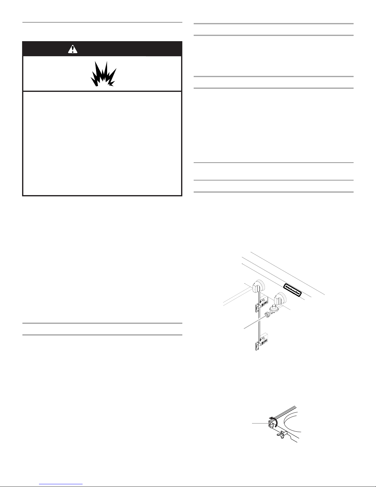
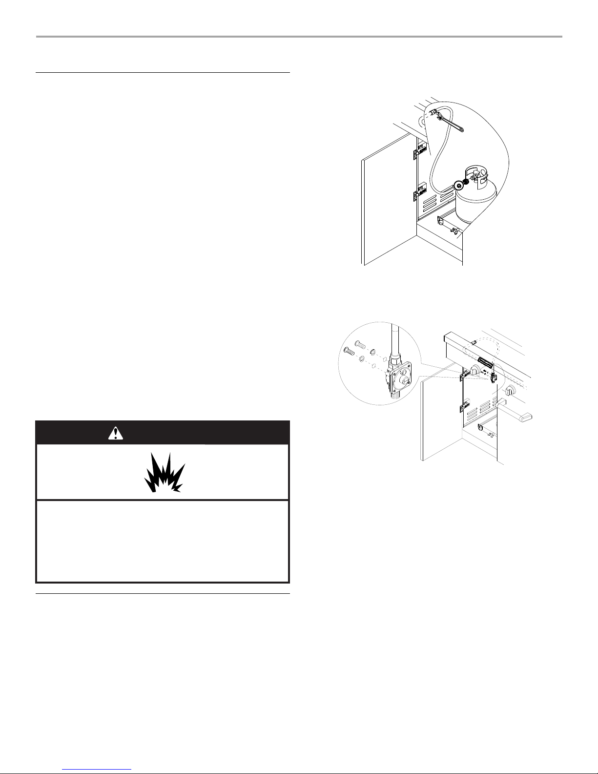
A. Gas pressure regulator/hose assembly
The 20 lb LP gas fuel tank must be mounted and secured.
Door Style Tank Tray
1. Open cabinet doors.
2. Slide the tank tray locking bracket counterclockwise 90° and
pull out the tray.
A. Tank tray locking bracket
7
3. Place the 20 lb LP gas fuel tank bottom collar into the
A
C
B
A
A
B
C
mounting hole in the tank tray.
4. Tighten the locking screw against the bottom collar of the
20 lb LP gas fuel tank to secure.
A. Locking screw
B. Bottom collar
C. Mounting hole
5. Slide the drawer with the 20 lb LP gas fuel tank back into the
cabinet. Turn the tank tray locking bracket clockwise 90° to
tighten.
A. Tank tray locking bracket
Natural Gas Conversion
Conversion must be made by a qualified gas technician. The
qualified Natural gas technician shall provide the Natural gas
supply to the selected grill location in accordance with the
National Fuel Gas Code ANSI Z223.1/NFPA 54 - latest edition,
and local codes. For conversion to Natural gas, the Natural Gas
Conversion Kit supplied with the grill (on some models) or the
Natural Gas Conversion Kit Part Number 710-0003 must be
used. See “Assistance” section for information on ordering.
IMPORTANT: The gas installation must conform with local
codes, or in the absence of local codes, with the National Fuel
Gas Code, ANSI Z223.1/NFPA 54 - latest edition.
Follow instructions for converting to Natural gas in the “Gas
Conversions” section of this manual or the instructions supplied
with Natural Gas Conversion Kit Part Number 710-0003.
The gas supply line shall be equipped with an approved shutoff
valve. This valve should be located in the same area as the grill
and should be in a location that allows ease of opening and
closing. Do not block access to the shutoff valve. The valve is for
turning on or shutting off gas to the grill.
A. Gas supply line
B. Shutoff valve “open” position
C. To grill
8
02
15
12
14
01
08
11
16
82
84
85
02
78
81
80
79
13
46
48
49
65
45
53
36
67
38
53
33
75
53
53
61
68
70
69
71
72
73
39
42
41
64
07
06
52
34
20
63
17
09
62
74
40
40
40
40
13
22
25
21
26
23
35
03
04
05
18
19
60
28
30
51
54
55
55
54
56
57
37
47
77
76
76
66
32
43
43
44
24
27
29
59
58
31
48
50
86
83
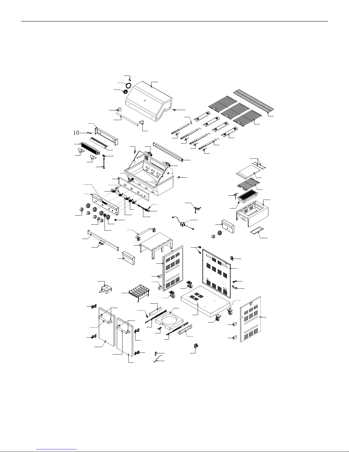
REPLACEMENT PARTS
9
9

Part
Number
Part (description) Warranty
Coverage
01 Main lid 3 1
02 Main lid screw 3 2
03 Temperature gauge
1 1
housing
04 Temperature gauge 1 1
05 Logo 1 1
06 Main lid handle seat, left 1 1
07 Main lid handle seat, right 1 1
08 Main lid handle tube 1 1
09 Rear baffle 1 1
10 Rotisserie burner ignition
1 1
wire
11 Rotisserie heat shield 1 1
12 Rotisserie burner 1 1
13 Rotisserie burner igniter
1 2
bracket
14 Rotisserie burner flex gas
1 1
line
15 Rotisserie burner with
1 1
brass elbow
16 Main lid bracket, left 1 1
17 Main lid bracket, right 1 1
18 Front baffle 1 1
19 Regulator, LP 1 1
20 Sear gas valve 3 1
21 Side manifold 1 1
22 Side burner flex gas line 1 1
23 Rotisserie gas valve 3 1
24 Main manifold 1 1
25 Igniter junction wire 1 1
26 Main gas valve 3 4
27 Main control panel 3 1
28 Light switch 1 1
29 Control knob 1 5
30 Bezel 1 5
31 Control knob bezel,
1 1
rotisserie burner
32 Control knob, rotisserie
1 1
burner
33 Cart frame, front 1 1
34 Door magnet 1 2
35 Push bar, side shelf 3 1
36 Side shelf, left 3 1
37 Side shelf front panel, left 3 1
38 Rubber grommet 1 3
39 Side panel, left 3 1
Quantity
Part
Number
Part (description) Warranty
Coverage
40 Door hinge bracket 1 4
41 Swivel caster with brake 1 1
42 Swivel caster 1 1
43 Caster 1 2
44 Bottom panel 1 1
45 Tan k tr ay 1 1
46 Gas tank tray slide
1 1
bracket, left
47 Gas tank tray slide
1 1
bracket, right
48 Gas tank tray slide 1 2
49 Tan k tr ay b ol t 1 1
50 Gas tank tray block piece 1 1
51 Cart basket 1 1
52 Grease box 1 1
53 Door hinge 1 4
54 Door handle seat 1 4
55 Door handle tube 1 2
56 Door, left 3 1
57 Door, right 3 1
58 Lighting rod 1 1
59 Lighting rod cover 1 1
60 Electric igniter module 1 1
61 Side panel, right 3 1
62 Cable strainer securing
1 1
plate
63 Cable strainer 1 1
64 Back panel 3 1
65 Igniter wire cover 1 1
66 Side burner control panel,
3 1
right
67 Side burner bowl
1 1
assembly
68 Side burner grease tray 1 1
69 Sear burner 1 1
70 Sear burner igniter wire 1 1
71 Sear burner cooking grid
3 1
with hole
72 Side burner lid 3 1
73 Side burner lid hinge rod 1 2
74 Transformer 1 1
75 Lamp cord 1 1
76 Lamp 1 2
77 Lamp case 1 1
78 Main burner igniter wire A 1 1
79 Main burner igniter wire B 1 1
Quantity
10

Part
Number
Part (description) Warranty
Coverage
80 Main burner igniter wire C 1 1
81 Main burner igniter wire D 1 1
82 Main burner 5 4
83 Flame tamer 3 4
84 Cooking grid with hole 3 3
85
86
Warming rack
Burner pin assembly
3
1
Quantity
1
4
Part
Number
Part (description) Warranty
Coverage
Natural gas orifice rack
Preassembly hardware
Manual
Carton body
Carton lid
Carton bottom
Quantity
11
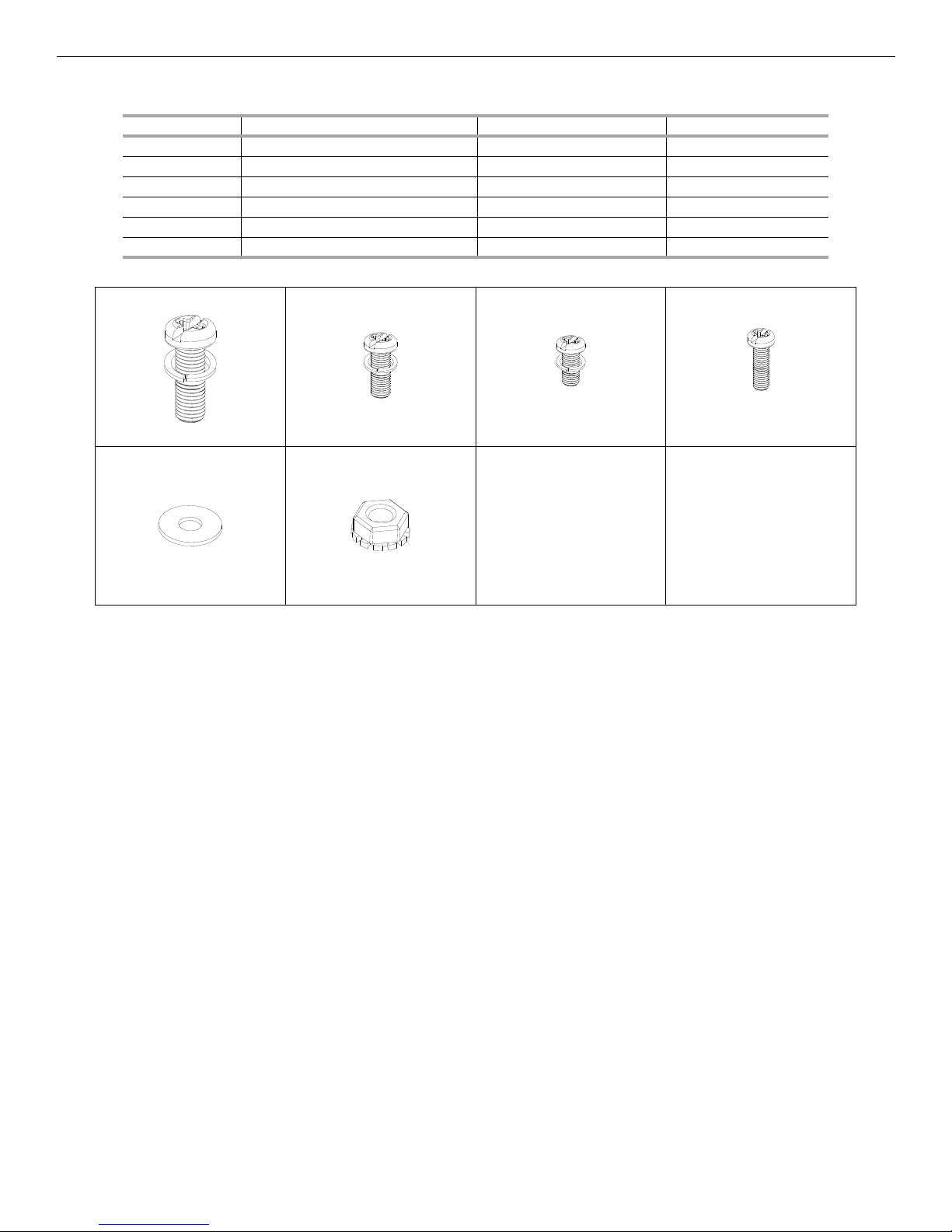
All Pre-Assembled Screws List
Sort Description Size Quantity
1 ¹⁄₄ Screw (with washer) ¹⁄₄*12mm 16
2 ⁵⁄₃₂ Screw (with washer) ⁵⁄₃₂*12mm 5
3 M4 Screw (with washer) M4*8mm 2
4 ⁵⁄₃₂ Screw ⁵⁄₃₂*12mm 4
5 ⁵⁄₃₂ Flat washer 6
6 ⁵⁄₃₂ Lock nut 2
1 2 3 4
5 6
12
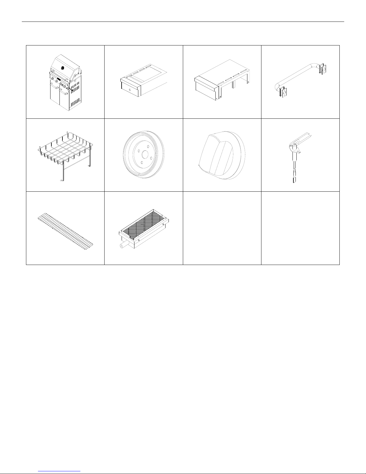
Package Content List
Side Burner Assembly Side Shelf Assembly Push Bar
Wire Basket Bezel Control Knob Side Burner Ignitor
Warming Rack Searing Burner
13
INSTALLATION INSTRUCTIONS
Excessive Weight Hazard
Use two or more people to move and install grill.
WARNING
Failure to do so can result in back or other injury.
A
A
B
A
B
Freestanding Outdoor Grill Installation
Unpack Grill
1. Remove all packaging materials and remove grill from the
shipping base.
2. Move grill close to desired outdoor location.
3. Open the grill hood.
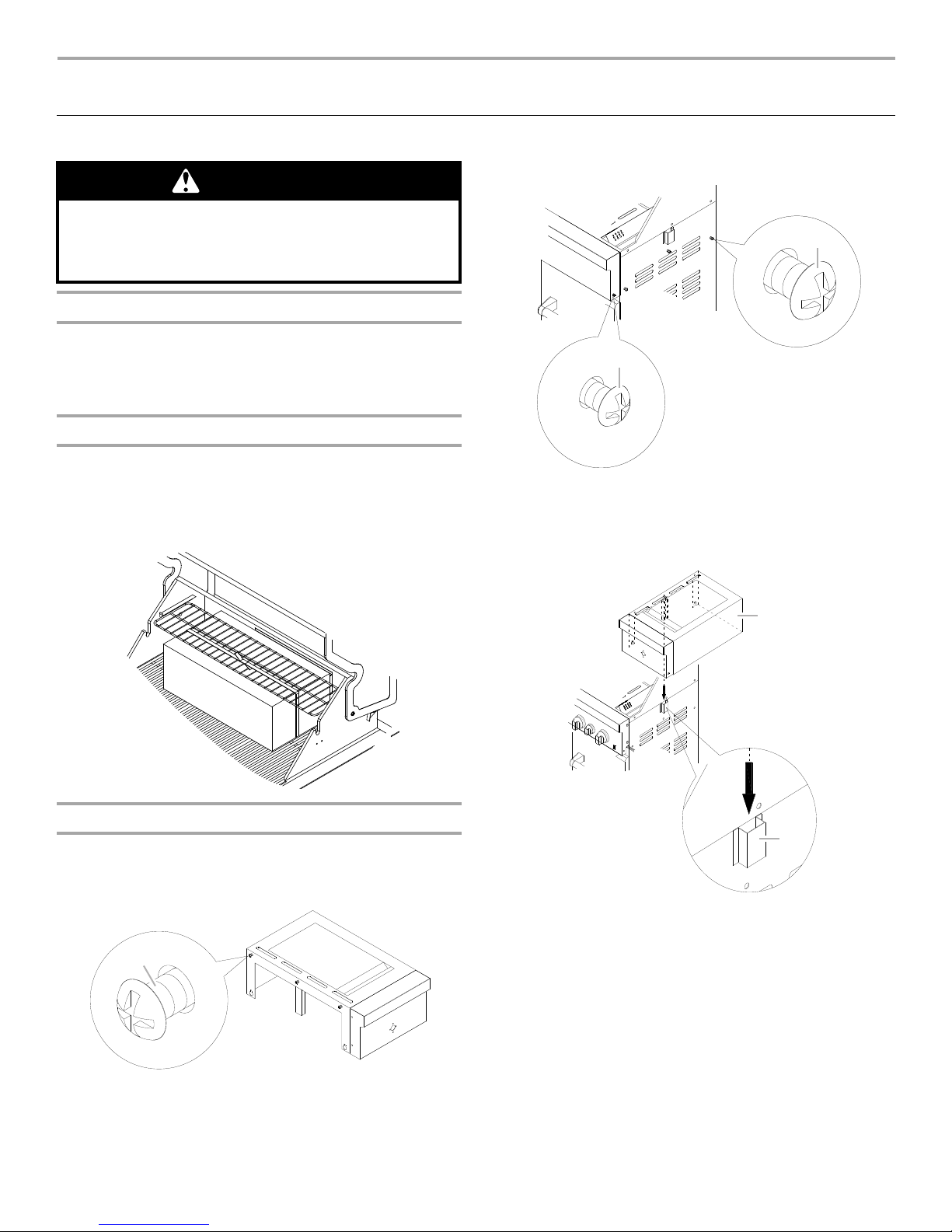
Remove Packaging Material Inside the Grill
1. Use a utility knife to cut yellow straps and packing tape to
open box from top and remove the boxes.
2. Remove the warming shelf and grill grates from inside the grill
and remove the package inside the firebox.
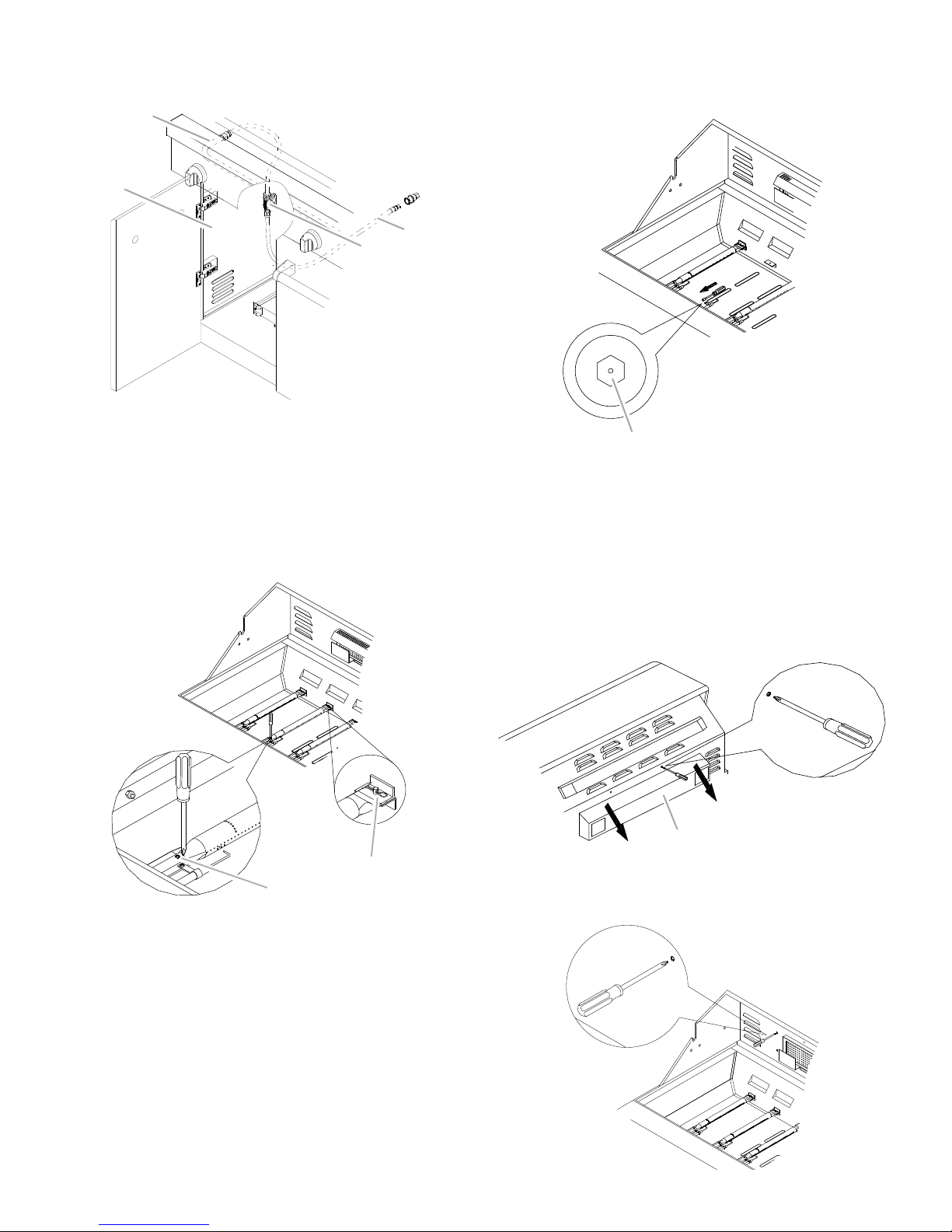
3. Remove foam block and wrap from inside the grill.
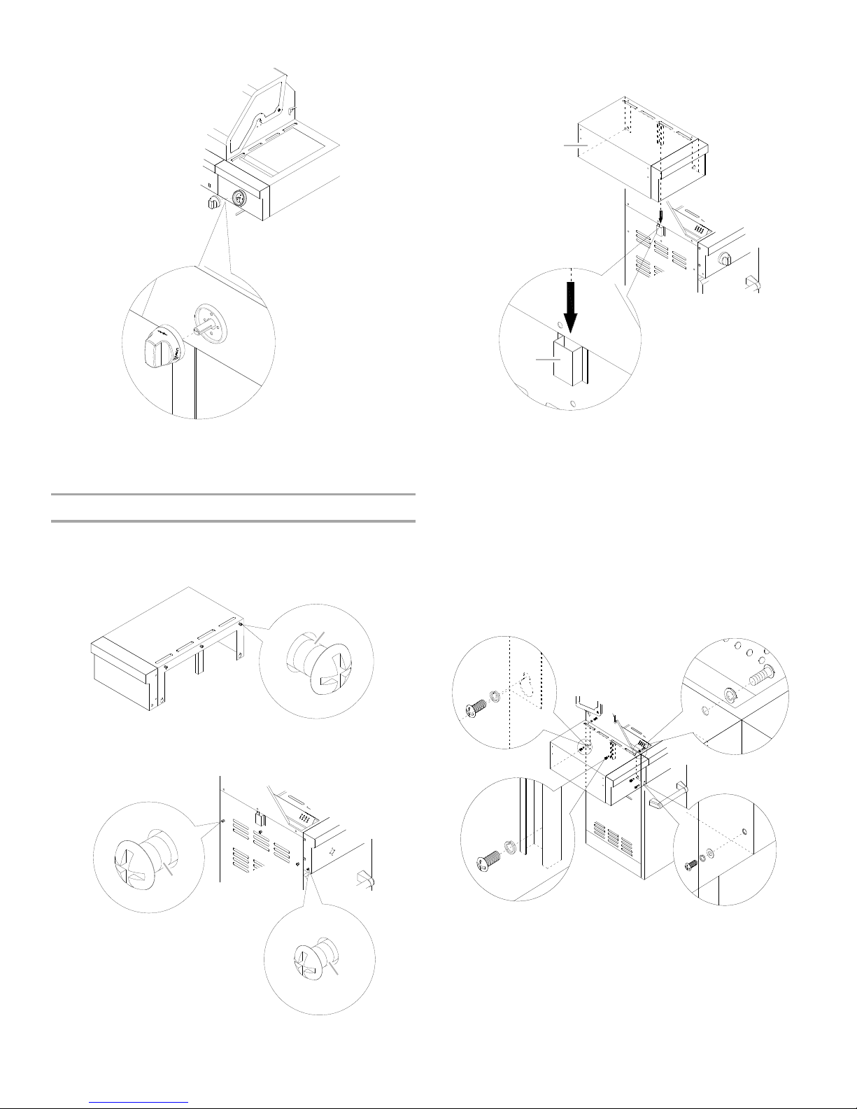
4. Remove the screws from the central post, then 2 screws on
the grill side panel and 1 screw on the grill control panel.
A. Grill control panel screw
B. Grill side panel screws
5. Lower the side shelf so that the center post (A) slides into the
bracket (B) and align the bottom keyhole slots on the side
shelf with the screw holes on the grill side panel.
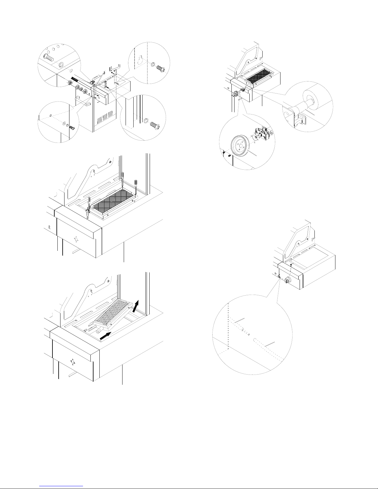
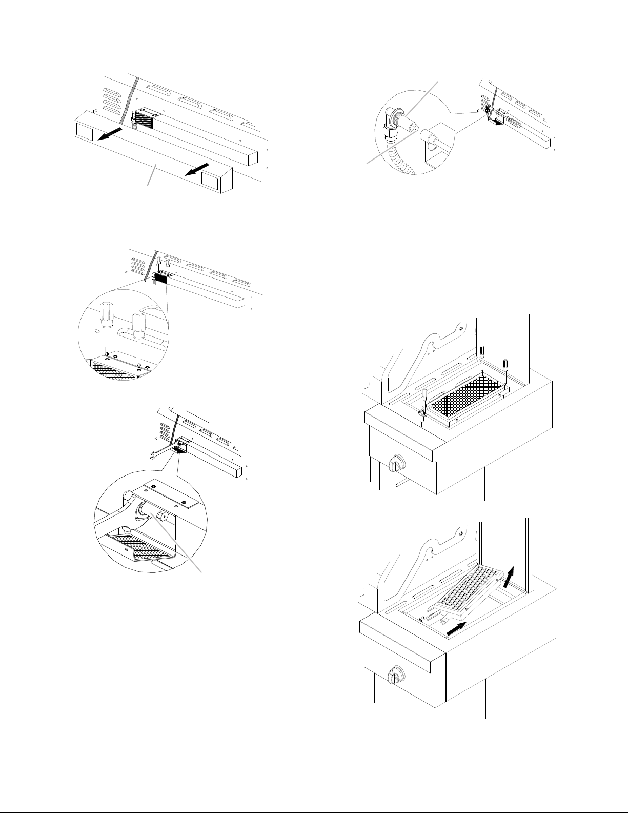
Attach Right Side Shelf with Sear Burner
1. Unpack right side shelf with sear burner.
2. Open grill lid.
3. Remove 3 screws from the side of the searing side burner.
A. Searing side burner screws
14
IMPORTANT: This step is meant to help with the installation, but
do not depend solely on the bracket to hold the weight of the
sear burner.
6. Attach the top of the side shelf to the grill (A) by inserting the
3
screws removed in Step 3 into the side shelf from inside the
grill hood and tighten. See illustration in Step 8.
7. Attach the bottom of the side shelf to the side panel (B and C)
of the grill by inserting the 3
side panel in Step
forward to install the center screw (C). Tighten the screws.
See illustration in Step
4. The drip pan may need to be pulled
screws removed from the grill
8.
8. Attach the side shelf to the control panel (D) by inserting the
A
B
CD
A
B
A
B
screw removed from the grill control panel in Step
4. Tighten
the screw.
9. Remove the 3 screws from the searing side burner.
13. Slide the bezel opening over the valve stem and attach the
side burner valve assembly and bezel to the side burner shelf
with the screws removed in Step 11.
A. Bezel
B. Valve stem
14. Replace the searing side burner, angling it so that the side
burner tube slides over the valve orifice. Locked 3 screws
removed in step 9.
15. Connect electrical plugs on underside of sear burner.
10. Remove the searing side burrner.
A. Electrical plug from grill
11. Remove the 2 screws from the side burner valve assembly.
See illustration in Step
13.
B. Electrical plug from sear burner
12. Push the valve stem out through the opening in the front of
the side burner shelf, lining up the holes in the side burner
valve assembly with the openings on the side burner shelf.
See illustration in Step
13.
15
16. Insert the valve stem into the knob and push knob into place.
A
A
B
A
B
AB
DC
5. Lower the side shelf so that the side shelf center post (A)
slides into the bracket (B) and align the bottom keyhole slots
on the side shelf with the screw holes on the grill side panel.
17. The igniter battery is not factory installed. A “AA” size alkaline
battery is located in the accessory box on the grill grate.
Install battery at this time following the instructions in
“Replacing the Igniter Battery” section.
Attach Left Side Shelf
1. Unpack left side shelf.
2. Open grill lid.
3. Remove 3 screws from the side of the side shelf.
A. Side shelf screws
4. Remove the screw from the central post, then 2 screws on
the grill side panel and 1 screw on the grill control panel.
IMPORTANT: This step is meant to help with the installation, but
do not depend solely on the bracket to hold the weight of the
side shelf.
6. Attach the top of the side shelf to the grill (B) by inserting the
3
screws removed in Step 3 into the side shelf from inside the
grill hood and tighten. See illustration in Step
8.
7. Attach the bottom of the side shelf to the side panel (A and D)
of the grill by inserting the 3
side panel in Step
4. The drip pan may need to be pulled
screws removed from the grill
forward to install the center screw (D). Tighten the screws.
See illustration in Step
8.
8. Attach the side shelf to the control panel (C) by inserting the
screw removed from the grill control panel in Step
4. Tighten
the screw.
A. Grill side panel screws
B. Grill control panel screw
16
9. Make sure that the push bar screw cover is separated from
B
A
WARNING
Explosion Hazard
Securely tighten all gas connections.
If connected to LP, have a qualified person make sure
gas pressure does not exceed 11” (28 cm) water
column.
Examples of a qualified person include:
licensed heating personnel,
authorized gas company personnel, and
authorized service personnel.
Failure to do so can result in death, explosion, or fire.
A
the the screw plate.
10. Remove the 2 screws and washers from the side of left side
shelf. Attach side shelf push bar by aligning the screw holes
on the side shelf with the screw holes in the push bar. Insert
the screws into the push bar screw holes and then into the
side shelf and tighten. Push in the push bar screw covers on
both sides to cover the screws.
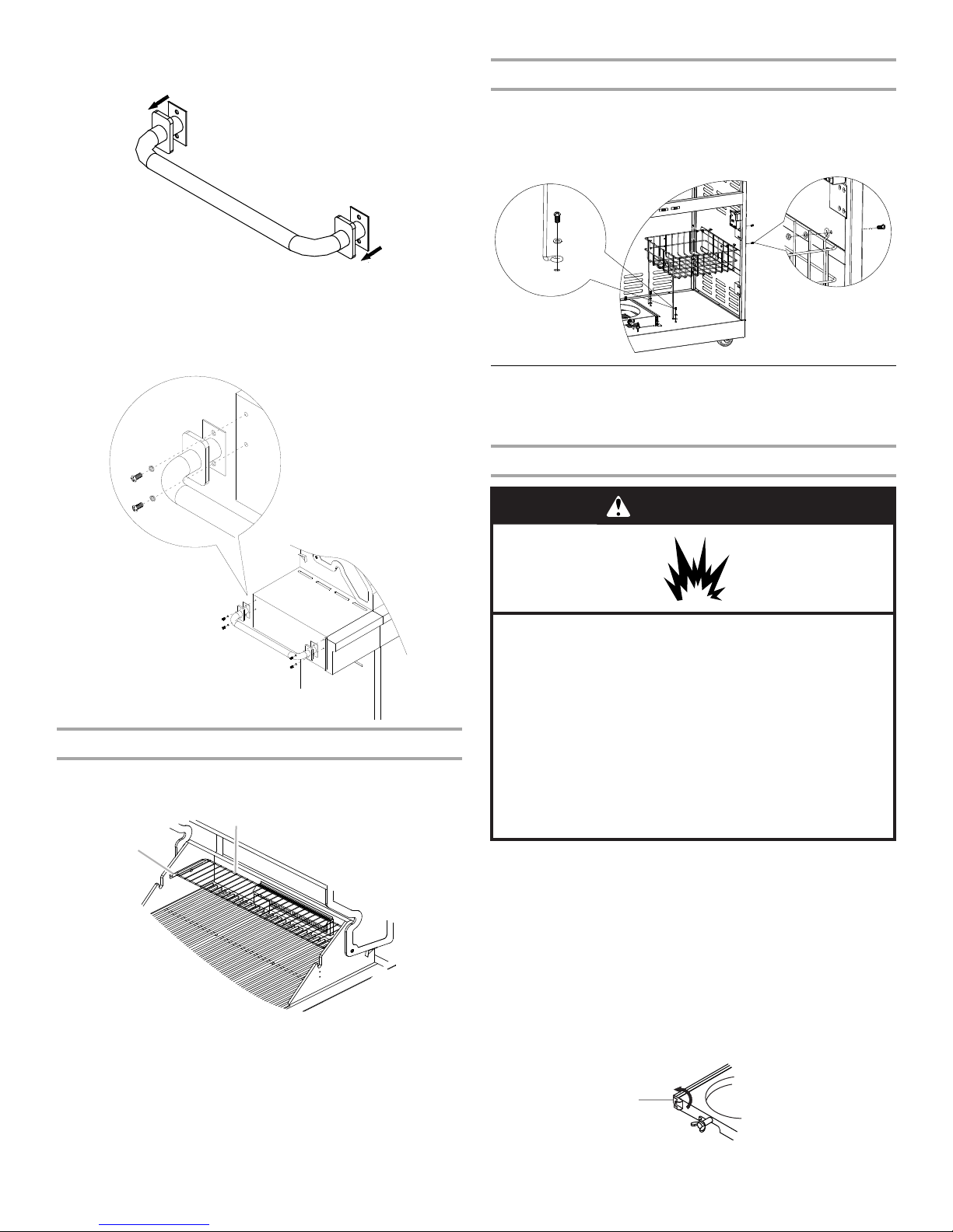
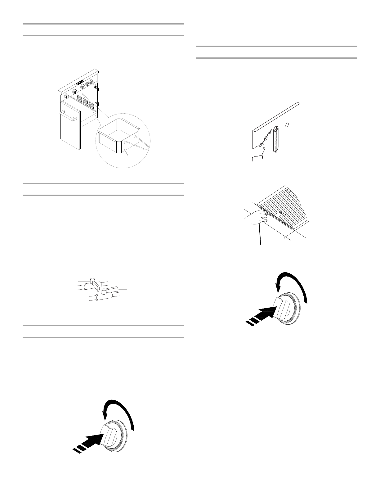
Attach Cart Basket
1. Remove 2 screws on the side panel and 2 screws on the
bottom panel.
2. Attach basket to the side panel and bottom panel by using
the screws removed in step 1.
Make Gas Connection
NOTE: If grill is to be converted to Natural gas, follow instructions
in the “Gas Conversions” section.
20 lb LP Gas Fuel Tank
Complete Assembly
1. Replace the grill grates.
2. Place warming shelf on brackets as shown..
A. Warming shelf brackets
B. Warming shelf
LP Gas:
IMPORTANT: A 20 lb LP gas fuel tank must be purchased
separately.
IMPORTANT: The gas pressure regulator/hose assembly
supplied with the grill must be used. Replacement gas pressure
regulator/hose assembly specific to your model, is available from
your outdoor grill dealer.
Door Style Tank Tray
1. Open cabinet doors.
2. Slide the tank tray locking bracket counterclockwise 90° and
pull out the tray.
A. Tank tray locking bracket
17
3. Place the 20 lb LP gas fuel tank bottom collar into the
A
C
B
A
B
mounting hole in the tank tray.
4. Tighten the locking screw against the bottom collar of the
20
lb LP gas fuel tank to secure.
A. Locking screw
B. Bottom collar
C. Mounting hole
5. Slide the tank tray with the 20 lb LP gas fuel tank back into
the cabinet and lock the locking bracket.
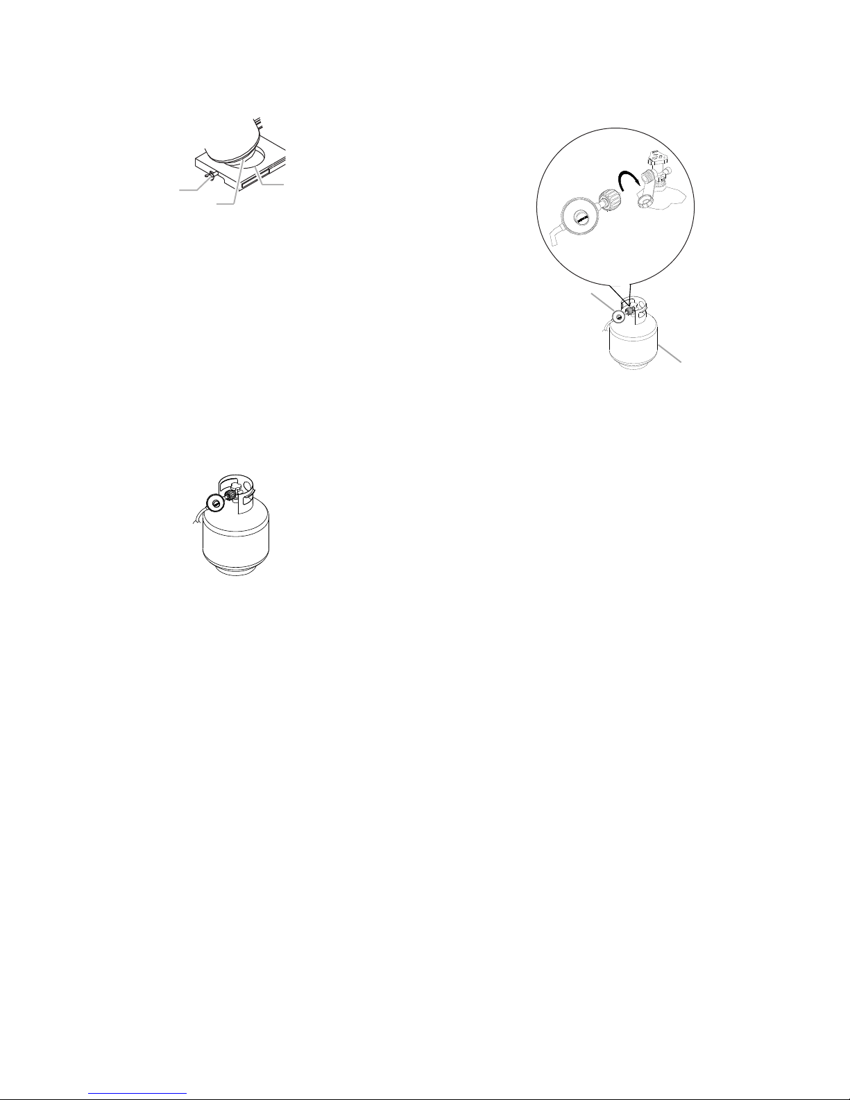
To Connect the 20 lb LP Gas Fuel Tank:
1. Check that the 20 lb LP gas fuel tank is in the “Off” position. If
not, turn the valve clockwise until it stops.
2. Check that the 20 lb LP gas fuel tank valve has the proper
type-1 external male thread connections per ANSI Z21.81.
3. Check that the burner control knobs are in the “Off” position.
4. Remove any debris and inspect the valve connections, port,
and gas pressure regulator/hose assembly for damage.
NOTE: Always keep the LP cylinder at 90° (upright)
orientation to provide vapor withdrawal.
5. Using your hand, turn the gas pressure regulator/hose
assembly clockwise to connect to the 20 lb LP gas fuel tank
as shown.
Hand tighten only. Use of a wrench could damage the quick
coupling nut.
A. Gas pressure regulator/hose assembly
B. 20 lb LP gas fuel tank
Make sure that the cylinder valve connection device properly
mates with the connection device attached to the inlet of the
pressure regulator.
6. Open the tank valve fully by turning the valve
counterclockwise. Wait a few minutes for gas to move
through the gas line.
7. Before lighting the grill, test all connections by brushing on an
approved noncorrosive leak-detection solution. Bubbles will
show a leak.
8. If a leak is found, turn the tank valve off and do not use the
grill. Contact a qualified gas technician to make repairs.
9. Go to “Check and Adjust the Burners” section.
18
To Disconnect the 20 lb LP Gas Fuel Tank:
A
B
Electrical Shock Hazard
Use only a UL listed, 14 gauge, 3 wire extension cord
approved for outdoor use, marked W-A, with a
maximum length of 50 ft.
Plug into a grounded 3 prong outlet.
Do not remove ground prong.
Do not use an adapter.
Failure to follow these instructions can result in death,
fire, or electrical shock.
WARNING
A
B
C
1. Check that the burner control knobs are in the “Off” position
and the grill is cool.
2. Check that the 20 lb LP gas fuel tank is in the “Off” position. If
not, turn the valve clockwise until it stops.
3. Using your hand, turn the gas pressure regulator/hose
assembly counterclockwise to disconnect to the 20 lb LP gas
fuel tank as shown.
Hand loosen only. Use of a wrench could damage the quick
coupling nut.
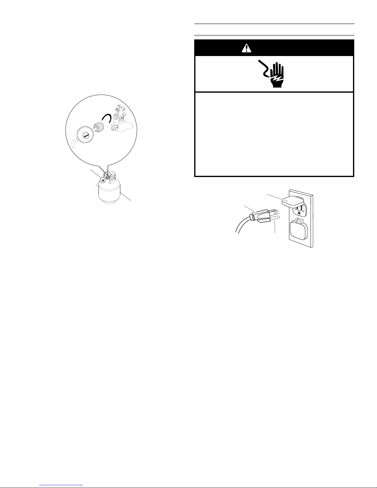
Plug in Grill
1. Plug extension cord into grounded 3-prong GFI outlet.
A. Gas pressure regulator/hose assembly
B. 20 lb LP gas fuel tank
4. Place dust cap on cylinder valve outlet whenever the cylinder
is not in use. Only install the type of dust cap on the cylinder
valve outlet that is provided with the cylinder valve. Other
types of caps or plugs may result in leakage of propane.
5. Go to “Plug in Grill” in this section.
A. 3-prong ground plug
B. 3-prong polarized type outdoor GFI outlet
C. Ground prong
■ To avoid electrical shock, do not immerse cord or plugs in
water or other liquid.
■ Unplug from the outlet when not in use and before
cleaning. Allow to cool before putting on or taking off
parts.
■ Do not operate any outdoor cooking gas appliance with a
damaged cord, damaged plug, or after the appliance
malfunctions or has been damaged in any manner.
Contact the manufacturer for repair.
■ Do not let the cord hang over the edge of a table or touch
hot surfaces.
■ Do not use an outdoor cooking appliance for purposes
other than intended.
■ When connecting, first connect plug to the outdoor
cooking gas appliance then plug appliance into the outlet.
■ Use only a Ground Fault Interrupter (GFI) protected circuit
with this outdoor cooking gas appliance.
■ Do not remove the ground prong or use with an adapter
of 2 prongs.
■ Use only extension cords with a 3 prong grounding plug
rated for the power of the equipment and approved for
outdoor use with a W-A marking.
2. Go to “Check and Adjust the Burners” section.
19
GAS CONVERSIONS
WARNING
Explosion Hazard
Use a new CSA International approved “outdoor”
gas supply line.
Securely tighten all gas connections.
Failure to do so can result in death, explosion, or fire.
†®TEFLON is a registered trademark of E.I. Du Pont De Nemours and Company.
Tools and Parts for Gas Conversion
Gather the required tools and parts before starting installation.
Read and follow the instructions provided with any tools listed
here.
Tools needed
■ Phillips screwdriver
■ Pipe wrench
■ Adjustable wrench
■ 6 mm socket and wrench
or 6 mm nut driver
Parts supplied
■ Natural gas orifices
Parts needed
■ Natural gas conversion kit Part Number 710-0003. See
“Assistance” section to order. The conversion kit includes:
■ Natural gas regulator 4" W.C. (marked “Natural Gas
Regulator”)
■ 10 ft (3.0 m) Natural gas hose with quick connector
■ 5.9" (150 mm) Natural gas regulator hose
■ 6 mm nut driver
■ 6 mm wrench
■ Hex key
IMPORTANT: Gas conversions must be done by a qualified
installer. Before proceeding with conversion, shut off the gas
supply to the appliance prior to disconnecting the electrical
power.
■ Thin flat-blade screwdriver
■ Pliers
■ Pipe thread sealant
certified for LP gas
6. Use an adjustable wrench to remove the LP regulator from
the manifold.
7. Use an adjustable wrench to install the Natural gas regulator
hose to the manifold and secure. Attach the Natural gas
regulator to the side panel inside the grill cart with the two
screws that are preassembled on the regulator.
Conversion from LP Gas to Natural Gas
Installation of the regulator
1. Turn off the main gas supply valve.
2. Unplug grill or disconnect power.
3. Disconnect 20 lb LP gas fuel tank (if present).
4. Turn off all burner control valves.
5. Remove the 20 lb LP gas fuel tank (if present) from the grill
cart.
20
Make Gas Connection
1. A combination of pipe fittings must be used to connect the
grill to the existing gas line.
■ The 10 ft (3.0 m) PVC flexible gas supply hose design-
certified by CSA must be used.
■ Pipe-joint compounds suitable for use with Natural gas
must be used. Do not use Teflon®† tape.
■ There must be a certified manual shut-off valve in the gas
supply line near the grill for easy access.
2. Connect the brass connector on one end of the 10 ft (3.0 m)
PVC flexible gas supply hose to the Natural gas pressure
regulator.
3. Connect the quick connector on the other end of the
A
B
C
D
A
B
A
A
ft (3.0 m) PVC flexible gas supply hose to the rigid Natural
10
gas supply pipe.
A. Left side panel
B. Manifold
C. 10 ft. (3.0 m) PVC gas hose
D. Natural gas pressure regulator/hose assembly
Change Grill Burner Valve Orifices
1. Remove the grates and flame tamers.
2. Remove the 1 screw and cotter clip that hold the burner in
place. Set the screw and clip aside. Remove the burner from
the grill by lifting the burner out.
3. Use a 6 mm socket and wrench or 6 mm nut driver to remove
the brass orifice from the end of gas valve. The main burner
orifice is located behind the LP orifice, so no additional orifice
needs to be installed.
A. Main burner orifice
IMPORTANT: Check that the orifice is properly installed
inside of the burner opening.
4. Reinsert the burner and reattach using the 2 screws
previously removed. Repeat the procedure for each main
burner.
5. Position the igniters so they are ¼" (6.0 mm) away from each
burner.
Change the Rotisserie/Infrared Burner Orifice
1. Using a Phillips screwdriver, unscrew the 2 screws and
remove the rotisserie/infrared burner wind baffle.
A. Wind baffle
2. Using a Phillips screwdriver, remove the 4 screws at the back
of grill from inside the grill (2 screws on each side of the
A. Screw
B. Cotter clip
rotisserie infrared burner).
21
3. Remove the access cover at the back of the grill hood by
A
A
A
B
removing the 4 screws (2 screws on each side of the
rotisserie infrared burner).
A. Access cover
4. Using a Phillips screwdriver, remove the 2 screws holding the
spider guard to the burner.
6. Take out the orifice support, and then use a 6 mm socket and
wrench or 6 mm nut driver to remove the LP orifice at the end
of the supply pipe. Replace with Natural gas orifice.
A. Orifice support
B. Orifice
IMPORTANT: Check that the orifice is properly installed
inside of the supply pipe.
7. Reinstall the orifice support and supply pipe and tighten the
nut with a 24 mm wrench.
8. Reinstall the spider guard, access cover, and wind baffle.
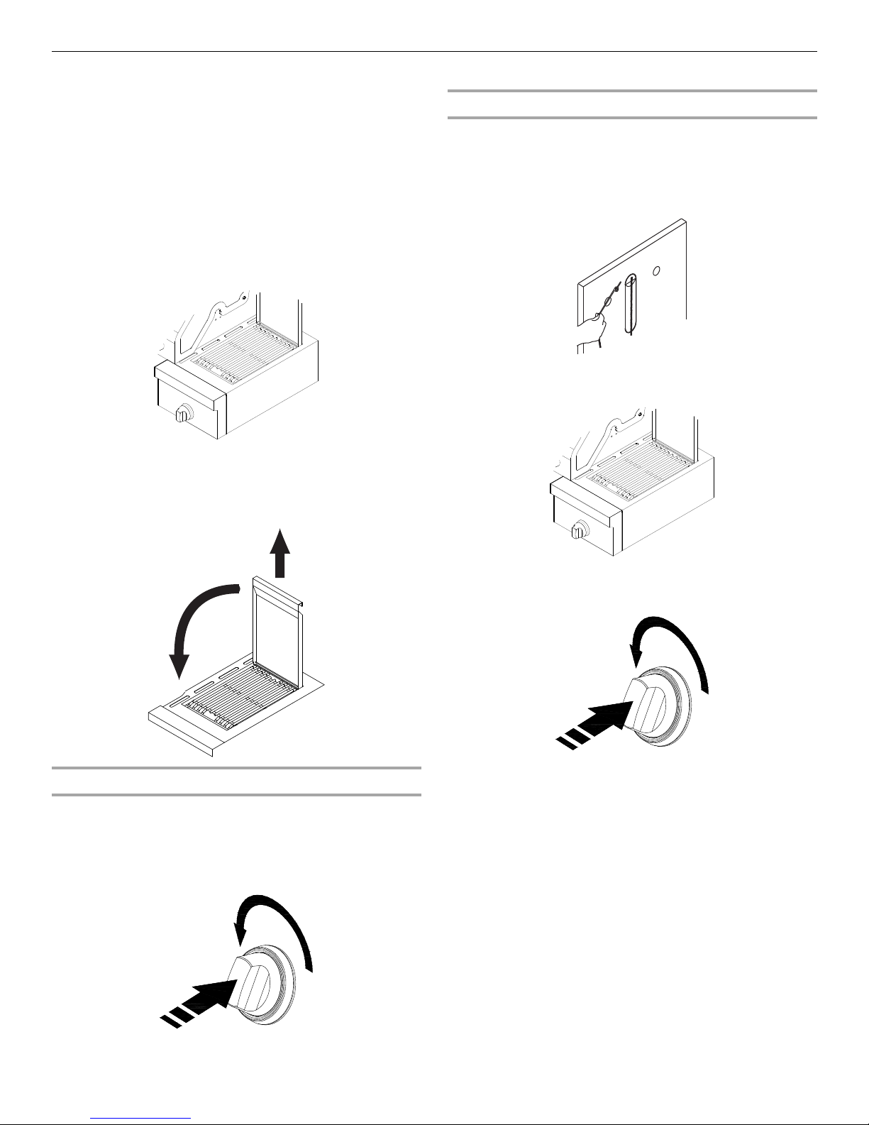
Change the Sear Burner Orifices
1. Remove the screw securing the igniter and the 2 searing side
burner screws.
5. Use 24 mm wrench to remove the orifice nut.
A. Orifice nut
2. Lift out the searing side burner.
22
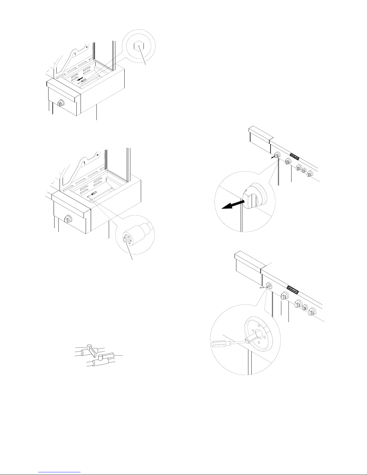
3. Locate the Liquid propane orifice at the end of the valve.
A
A
A
B
A. Orifice
4. Use 6 mm socket wrench or 6 mm nut driver to remove the
orifice. Replace with the Natural gas orifice.
Record Conversion
1. The appliance nameplate is located inside the grill cabinet on
the left-hand cabinet side. With a permanent marker, check
the box next to “Natural gas” and mark through “LP Propane.”
In the last page of the Use and Care Guide, write “Converted to
Natural Gas.” Also record the conversion date and the
technician/company that performed the conversion.
NOTE: Place LP gas parts in plastic parts bag for future use and
keep with pack containing literature.
Adjust High Flame Setting Screw
When converting from LP to Natural gas, you will need to adjust
the high flame setting screw for ideal burner flame height.
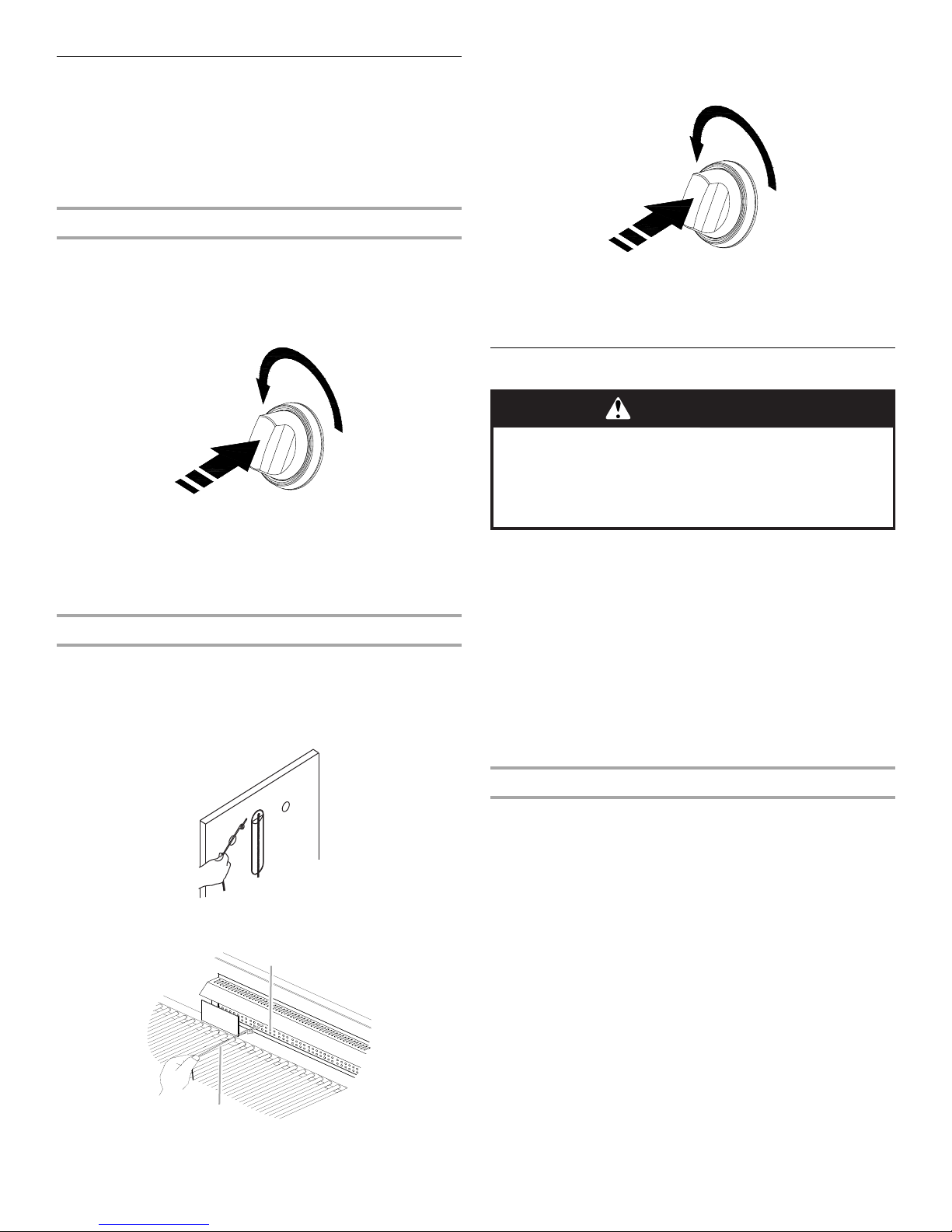
1. Remove each control knob for the main burner and side
burner.
A. Orifice
IMPORTANT: Check that the orifice is properly installed
inside of the valve.
5. Reinstall the searing side burner. Make sure that the igniter is
out of the way to allow proper positioning of burner. Use
Phillips screwdriver to attach the mounting screws.
6. Use Phillips screwdriver to reattach the igniter and searing
side burner plate.
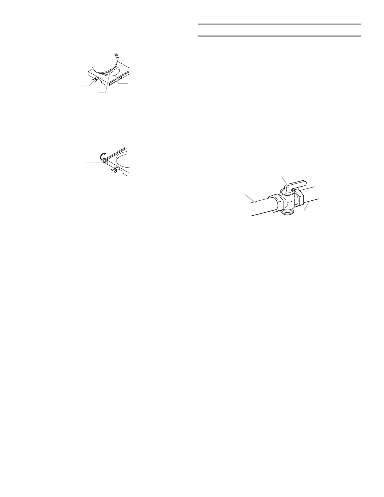
7. Open the manual shutoff valve in the gas supply line. The
valve is open when the handle is parallel to the gas pipe.
A. Closed valve
B. Open valve
8. Test all connections using an approved noncorrosive leak-
detection solution. Bubbles will show a leak. Correct any leak
found.
2. Use a flat-blade screwdriver to turn the high flame setscrew
counterclockwise approximate 90°.
3. Check that burner operates at the new high flame setting. It
may be necessary to adjust the screw setting slightly more to
get the ideal burner flame height.
23
Check and Adjust the Burners
1" (2.5 cm)
A
A
A
B
C
The burners are tested and factory-set for most efficient
operation. However, variations in gas supply and other conditions
may make minor adjustments to air shutter or low flame setting
necessary.
It is recommended that a qualified person make burner
adjustments.
NOTE: The rotisserie burner cannot be adjusted.
Checking and adjusting the grill burner flames requires removing
the grates and flame tamers.
6. If flame is yellow (not enough air), turn air shutter adjustment
screw counterclockwise.
If flame is noisy or lifts away from burner (too much air), turn
air shutter adjustment screw clockwise.
Burner Flame Characteristics
The flames of the grill burners and side burners (on some models)
should be blue and stable with no excessive noise or lifting (LP
gas flames will have a slightly yellow tip). A yellow flame indicates
not enough air. If flame is noisy or lifts away from the burner, there
is too much air. Some yellow tips on flames when the burner is
set to HIGH setting are acceptable as long as no carbon or soot
deposits appear. The flames should be approximately 1"
high.
Check that burners are not blocked by dirt, debris, insect nests,
etc., and clean burners as necessary. If they are clean, adjust air
shutters as needed.
IMPORTANT: Before adjusting air shutters, let burners cool
completely.
To Adjust:
1. Light grill using information in the “Outdoor Grill Use” section.
2. Observe flame to determine which burners need adjustment
and how the flame is acting.
3. Turn off the valve and wait until grill and burners cool
completely.
4. Remove grill grates and flame tamers.
5. Remove the 1 screw and cotter clip that hold the burner in
the place. Remove gas burner from the grill.
(2.5 cm)
A. Air shutter adjustment screw
Adjustment should be made clockwise or counterclockwise
from ¹⁄₈" (3.2 mm) to ¹⁄₄" (6.4 mm).
7. Replace gas burner, flame tamers and grates.
8. Light grill using information in the “Outdoor Grill Use” section.
See “Burner Flame Characteristics.”
Low Flame Adjustment
If flame goes out on the “LOW” setting, the low flame setting
must be adjusted.
1. Turn off the valve and wait until grill and burners are cool.
2. Remove grill grates and flame tamers.
3. Light grill using information in the “Outdoor Grill Use” section.
4. Turn burner to its lowest setting.
5. Remove each control knob for the main burner and side
burner.
6. Hold valve stem with pliers and insert a small flat-blade
screwdriver into the shaft.
7. Watch the flame and slowly turn the screwdriver
counterclockwise.
8. Adjust flame to minimum stable flame.
A. Screw
24
A. Valve stem
B. Small flat-blade screwdriver
C. Pliers
9. Replace the control knob and turn off the burner.
10. Repeat steps 3 through 9 for each burner if needed.
11. Replace the flame tamers and grates after the burners have
cooled.
OUTDOOR GRILL USE
E
D
C
BA
F
ON
OFF
G
WARNING
Explosion Hazard
Do not store fuel tank in a garage or indoors.
Do not store grill with fuel tank in a garage or indoors.
Failure to follow these instructions can result in death,
explosion, or fire.
WARNING
Fire Hazard
Do not use grill near combustible materials.
Do not store combustible materials near grill.
Doing so can result in death or fire.
WARNING
Food Poisoning Hazard
Do not let food sit for more than one hour before or
after cooking.
Doing so can result in food poisoning or sickness.
A
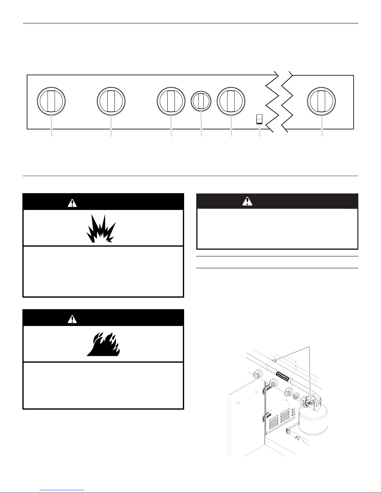
This manual covers several different models. The grill you have purchased may have some or all of the features listed. The locations and
appearances of the features shown here may not match those of your model.
Control Panel
A. Left grill burner knob
B. Left-center grill burner knob
C. Right-center grill burner knob
D. Rotisserie burner knob
Using Your Outdoor Grill
E. Right grill burner knob
F. Li gh t sw it c h
G. Sear burner knob
Inspect the LP Gas Fuel Tank Supply Hose
Inspect the gas pressure regulator/hose assembly before each
use.
1. Open left-hand cabinet door.
2. Inspect the gas pressure regulator/hose assembly for cuts,
abrasions, or excessive wear.
3. If necessary, replace the gas pressure regulator/hose
assembly before using the grill.
Contact the dealer and use only replacement hoses specified
for use with the grill.
A. Gas pressure regulator/hose assembly
25
Prepare the Grill for Lighting
A
A
B
1. Open the hood completely. Do not light burners with the hood
closed.
2. Make sure control knobs are turned to OFF. The drip pan
must be in place and pushed all the way to the back.
4. You will hear the “snapping” sound of the spark. When burner
is lit, release the knob. Turn knob to desired setting.
5. Repeat for each of the other burners as needed.
Manually Lighting the Grill Burners
1. Open the hood completely. Do not light burners with the hood
closed.
2. Do not lean over the grill.
3. Remove the manual lighting extension (see following
illustration) and attach a match to the split ring.
A. Drip pan
Turn the Gas Supply On
1. For outdoor grills using a 20 lb LP gas fuel tank:
Slowly open the tank valve.
NOTE: If flow limiting device activates, your grill may not
light. If your grill does light, the flames will be low and will not
heat properly. Turn tank valve and all control knobs off and
wait 30
seconds. After shutting off the tank, very slowly open
tank valve and wait 5 seconds before lighting.
2. For outdoor grills using gas supply source other than 20 lb LP
gas fuel tank:
Open the manual shutoff valve in the gas supply line. The
valve is open when the handle is parallel to the gas pipe.
A. Closed valve
B. Open valve
Lighting the Grill Burners
IMPORTANT: If burner does not light immediately, turn the
burner knob to OFF and wait 5 minutes before relighting.
1. Open the hood completely. Do not light burners with the hood
closed.
2. Do not lean over the grill.
3. Select the burner you want to light. Push in and turn the grill
burner control knob to IGNITE HIGH, while continuing to hold
it in.
4. Strike the match to light it.
5. Guide the lit match under the grill grate.
6. Push in and turn the burner knob to IGNITE HIGH for the
burner closest to the lit match. The burner will light
immediately. When burner is lit, turn knob to desired setting.
7. Repeat steps 2 through 6 for each main burner.
8. Remove match and replace manual lighting extension on the
right side panel.
IMPORTANT:
If burner does not light immediately, turn the burner knob to OFF
and wait 5 minutes before relighting.
If any burners do not light after attempting to light them manually,
contact the Customer Service Center. See the “Assistance”
section.
26
Hood Lights
The grill must be plugged in for the hood lights to work. See
“Plug in Grill” in the “
section.
To Us e:
Press the LIGHTS button on the control panel to turn the hood
lights on and off.
Freestanding Outdoor Grill Installation”
Using Your Searing Side Burner
1
2
Infrared grilling produces intense heat that quickly sears the
meat. Searing locks in flavor and juices while allowing the outer
surface to absorb smoke and food aroma that is produced as
grease and drippings are vaporized by the burner. The result is a
crisp, flavorful outside with a tender, juicy inside.
■ Preheat the infrared sear burner for 5 minutes.
■ Ensure that meats are fully thawed and that all excess fat is
trimmed away prior to grilling.
■ Leave the burner set to On when placing food on the grill to
sear.
■ Use the sear burner to sear meat 1 to 2 minutes on each side,
then move the meat to the main grill cooking surface to finish
grilling to the desired doneness.
IMPORTANT: It is recommended that the sear side burner lid
be open when the burner is in use to eliminate the possibility
of increased lid and handle temperatures.
■ To close the searing side burner lid, first lift up the lid to
release the lock then lower it to the closed position.
Manually Lighting the Searing Side Burner
1. Open the searing side burner cover. Do not light burners with
the cover on.
2. Do not lean over the grill.
3. Remove the manual lighting extension (see the following
illustration) and attach a match to the split ring.
4. Strike the match to light it.
5. Hold the lit match close to the searing side burner.
Lighting the Searing Side Burner
1. Open the searing side burner cover. Do not light burners with
the cover on.
2. Do not lean over the grill.
3. Push in and turn the control knob to IGNITE ON and hold in.
You will hear the “snapping” sound of the spark. When burner
is lit, release the knob. Turn knob to desired setting.
6. Push in and turn the burner knob to IGNITE ON for the burner
closest to the lit match. The burner will light immediately.
When burner is lit, turn knob to desired setting.
7. Repeat steps 3 through 6 for each burner.
8. Remove match and replace manual lighting extension on the
right side panel.
IMPORTANT:
If burner does not light immediately, turn the burner knob to OFF
and wait 5 minutes before relighting.
If any burners do not light after attempting to light them manually,
contact the Customer Service Center. See the “Assistance”
section.
IMPORTANT: If burner does not light immediately, turn the
burner knob to OFF and wait 5 minutes before relighting.
27
Using Your Rotisserie Burner
A
B
WARNING
Food Poisoning Hazard
Do not let food sit for more than one hour before or
after cooking.
Doing so can result in food poisoning or sickness.
A Rotisserie kit can be purchased as an accessory for the grill.
See “Accessories” in the “Assistance” section.
To avoid damage to the warming rack, remove from grill when
using the rotisserie burner.
IMPORTANT: Do not use the main burners when the rotisserie
burner is in use.
Lighting the Rotisserie Burner
6. Push in and turn the control knob to IGNITE ON. Hold this
knob in for 10 seconds after the burner is lit. You will hear the
“snapping” sound of the spark until after the knob is released.
1. Open the hood completely. Do not light burners with the hood
closed.
2. Do not lean over the grill.
3. Push in and turn the control knob to IGNITE ON. You will hear
the “snapping” sound of the spark.
4. When the rotisserie burner lights, continue to hold the knob in
for another 10 seconds, then release the knob and burner will
stay lit. You will hear the “snapping” sound of the spark until
the knob is released.
IMPORTANT: If the rotisserie burner does not light immediately,
turn the burner knob to OFF and wait 5 minutes before relighting.
Manually Lighting the Rotisserie Burner
1. Open the hood completely. Do not light burners with the hood
closed.
2. Do not lean over the grill.
3. Remove the manual lighting extension (see following
illustration) and attach a match to the split ring.
IMPORTANT: If the rotisserie burner does not light
immediately, turn the rotisserie burner control knob to OFF
and wait 5 minutes before relighting.
7. Remove the match and replace the manual lighting extension
inside the cabinet door.
Rotisserie Cooking Tips
Rotisserie cooking rotates food in front of the rotisserie burner,
creating an intense heat for searing the outside and sealing in
natural juices.
The rotisserie burner reaches cooking temperatures in about
1 minute. It is not necessary to preheat when using the rotisserie.
■ Select tender meat and poultry.
■ Allow at least 1" (2.5 cm) space between rotisserie burner
and the food.
■ To make cleanup easier, place a pan under the food to catch
drippings.
■ Add barbecue sauce or glaze only during the last 10 minutes
of cooking to keep sauce from burning.
4. Strike the match to light it.
5. Gently hold the lit match close to the rotisserie burner.
28
A. Lighting extension
B. Rotisserie burner
Trussing Poultry for the Rotisserie
1. Load the spit rod by sliding one of the forks on the rod, with
the prongs facing inward. Tighten the screw to keep it from
slipping.
2. Push the rod through the center of the bird.
3. Cut 24" (61.0 cm) of butcher’s string and center it under the
bird, breast side up.
4. Wrap each end of the string around the wings; catch each
wing tip. Bring the string tightly together at the top of the
breast and knot. It is not necessary to cut off the extra string.
5. Cut another 20" (50.8 cm) of string and lay it under the back
of the bird. Wrap it around the tail then around the spit rod,
cinching tightly.
6. Cross the legs on top of spit rod; tie string around the
crossed legs.
7. Connect the twine holding the legs, to the string holding the
wings, and knot. Cut off any bits of hanging string.
8. Slide on the second fork, pushing the tines into the
drumsticks.
9. Center the food and forks on the rod and tighten the thumb-
screws. The bird should be firmly in place on the rotisserie
spit rod.

ROTISSERIE
WARNING
Food Poisoning Hazard
Do not let food sit for more than one hour before or
after cooking.
Doing so can result in food poisoning or sickness.
CHART
Use a portable meat thermometer to check internal doneness of
the food.
Turn off rotisserie burner when meat thermometer reads 5°F/3°C
lower than desired internal temperature. Continue rotating, hood
closed, for 10 minutes before carving.
Timing is affected by weather conditions such as wind and
outside temperature.
TIPS FOR OUTDOOR
GRILLING
Food Weight Internal
Beef
Roasts
Rib Eye
Sirloin Tip
Rib, boneless
Poultry
Chicken
Turkey, whole
Lamb
Boneless leg 4-7 lbs
Pork
Loin roast,
boneless
4-6 lbs
(1.5-2.2 kg)
3-6 lbs
(1.1-2.2 kg)
7-10 lbs
(2.6-3.7 kg)
(1.5-2.6 kg)
4-6 lbs
(1.5-2.2 kg)
Doneness or
Temperature
(°F/°C)
Medium-rare
(145°F/ 63°C)
Medium
(160°F/71°C)
Breast
(170°F/ 77°C)
Thigh
(180°F/82°C)
Breast
(170°F/77°C)
Thigh
(180°F/82°C)
Medium
(160°F/71°C)
Medium
(160°F/71°C)
Approximate
Grilling Time
(min/lb)
15-20
20-25
25-30
25-30
11-20
11-20
20-25
20-23
Before Grilling
■ Thaw food items before grilling.
■ Preheat grill on high (use all grill burners) 10 minutes. The
hood must be closed during preheating. There is no need to
use the back rotisserie burner for preheating. Preheating
provides the high heat needed to brown and seal the juices.
■ Shorten the preheat time when grilling high-fat cuts of meat
or poultry, such as chicken thighs. This will help reduce
flare-ups.
■ Lightly oil the grill grates or the food when cooking low-fat
cuts of meat, fish or poultry, such as lean hamburger patties,
shrimp or skinless chicken breasts.
■ Using too much oil can cause gray ash to deposit on food.
■ Trim excess fat from meats prior to cooking to reduce
flare-ups.
■ Make vertical cuts at 2" (5 cm) intervals around the fat edge
of meat to avoid curling.
■ Add seasoning or salt only after the cooking is finished.
During Grilling
■ Turn foods only once. Juices are lost when meat is turned
several times.
■ Turn meat just when juices begin to appear on the surface.
■ Avoid puncturing or cutting the meats to test doneness. This
allows juices to escape.
■ It may be necessary to lower the heat setting for foods that
cook a long time or are marinated or basted in a sugary
sauce.
■ If using a high flame, add barbecue sauce only during the last
10 minutes of cooking to avoid burning the sauce.
■ The degree of doneness is influenced by the type of meat, cut
of meat (size, shape and thickness), heat setting selected,
and length of time on the grill.
■ Cooking time will be longer with an open grill cover.
29

Cooking Methods
Direct Heat
Cooking by direct heat means the food is placed on grill grates
directly above lighted burners. Hood position can be up or down.
If hood is in the up position, total cooking times may be longer.
Direct heat sears the food. Searing is a process that seals natural
juices in food by cooking with intense heat for a short period of
time. While juices stay inside, the outside is browned with a
flavorful grilled coating.
Grilling Chart
■ Knobs have High, Medium and Low settings for flame
adjustment.
■ Heat settings indicated are approximate.
■ Grilling times are affected by weather conditions.
Indirect Heat
For best results, do not select the indirect heat cooking method
when it is windy.
Cooking by indirect heat means the food is placed on the grill
grate above an unheated burner, allowing heat from lighted
burner(s) on either side to cook the food.
If possible, turn on 2 burners. Cook with the hood down. This will
shorten the cooking time.
■ When 2 temperatures are listed, for example: Medium to
Medium-Low, start with the first and adjust based on cooking
progress.
■ Cooking times may vary from chart times depending on the
type of fuel, Natural or LP gas.
FOOD COOKING METHOD/
BURNER SETTING
Beef
Hamburgers ½" (1.3 cm) to
¾" (1.9 cm) thick
Roasts
Rib Eye, Sirloin
Steaks, 1" (2.5 cm)
Porterhouse, Rib, T-bone,
Top L oin , Sir loi n
Steaks, 1½" (3.8 cm)
Porterhouse, Rib, T-bone,
Top L oin , Sir loi n
Top Round or Shoulder/
Chuck (London Broil)
1½" (3.8 cm) thick
Flank, ½" (1.3 cm) thick
Pork
Chops,
1" (2.5 cm)
1½" (3.8 cm) thick
Ribs
2½-4 lbs (0.9-1.5 kg)
Roast, boneless tenderloin,
1 lb (0.37 kg)
Ham half,
8-10 lbs (3-3.7 kg)
DIRECT
Medium
INDIRECT
Medium/OFF/Medium
DIRECT
Medium
DIRECT
Medium
DIRECT
Medium
DIRECT
Medium
DIRECT
Medium to Med-Low
INDIRECT
Med/OFF/Med
DIRECT
Medium
INDIRECT
Med/OFF/Med
INTERNAL TEMP. TIME
(total minutes)
Medium (160°F/71°C)
Med-Rare (145°F/63°C)
to Medium (160°F/71°C)
Med-Rare (145°F/63°C)
to Medium (160°F/71°C)
Med-Rare (145°F/63°C)
to Medium (160°F/71°C)
Med-Rare (145°F/63°C)
to Medium (160°F/71°C)
Med-Rare (145°F/63°C)
Medium (160°F/71°C)
Medium (160°F/71°C)
Medium (160°F/71°C)
Reheat (140°F/60°C)
10-15
32-40 per lb
(15-18 per kg)
11-16
18-25
22-29
11-16
12-22
30-40
40-60
18-22
2-2½ hours
SPECIAL INSTRUCTIONS
Grill, turning once.
Tent with foil first 45-60 minutes
of cooking time.
Rotate steaks ¼ turn to create
criss-cross grill marks.
Grill, turning occasionally.
During last few minutes, brush
with barbecue sauce if desired.
When done, wrap in foil.
Turn during cooking to brown
on all sides.
Wrap entire ham in foil and put
on grill without pan or drip pan.
Ham steak precooked,
½" (1.3 cm) thick
Hot Dogs
Chicken
Breast, boneless
Pieces, 2-3 lbs
(0.75-1.1 kg)
DIRECT
Preheat Medium
Grill Medium
DIRECT
Medium
DIRECT
Medium
DIRECT
Med-Low to Medium
30
Reheat (145°F/63°C)
Reheat (145°F/63°C)
170°F/77°C
Breast 170°F/77°C
Thigh 180°F/82°C
7-10
5-10
15-22 For even cooking, pound breast
Slit skin if desired.
to ¾" (2.0 cm) thick.
Start bone side down.
 Loading...