

FREESTANDING OUTDOOR GRILL
InstallationInstructionsan
dUse&CareGuide
F
or questions about features, operation/performance, parts, accessories or service, call: 1-877-373-2301
or visit our website at www.Kitchenaidgrills.com
ASADOR AUTÓNOMO PARA EXTERIORES
Instrucciones
deinstalación yManualdeuso ycuidado
Para consu
ltas respecto a características, funcionamiento, rendimiento, piezas, accesorios o servicio técnico, llame al: 1-877-373-2301
o visite nuestro sitio de internet en www.Kitchenaidgrills.com
GRIL D'EXTÉRIEUR AUTOPORTANT
Instructionsd’installation
etGuided’utilisation etd’entretien
Pour des qu
estions à propos des caractéristiques, du fonctionnement/rendement, des pièces, des accessoires ou du service,
composer le : 1-877-373-2301
ou visiter notre site web www.Kitchenaidgrills.com
Table of Contents/Índice/Table des matières................................................................................. 2
7
20-0709C (LP) 730-0709C(NG)
1900
0395A0

OUT
DOOR GRILL SAFETY…………………………………2
INSTALLATION REQUIREMENTS…………………….…..5
Tools and Parts…..………………………………………5
Location requirements……………………………….….5
Product Dimensions……………………………………..6
Gas Supply Requirements………………………………6
Gas Connection Requirements…………………………7
PACKAGE CONTENTS LIST ………………………………8
REPLACEMENT PARTS…………………………………….9
INSTALLATION INSTRUCTIONS…………………..……..12
Freestanding Outdoor Grill Installation………………12
Make Gas Connection…………………………...…….15
GAS CONVERSION…………………………………............16
Tools and Parts for Gas Conversion……………….....16
Conversion from LP Gas to Natural Gas……………...17
Check and Adjust the burners…………………………20
TABLE OF CONTENTS
OUT
DOOR GRILL USE…………………………………………21
Using Your Outdoor Grill…………………………....……….21
TIPS FOR OUTDOOR GRILLING……………..………………24
Cooking Methods…………………………………………….24
Grilling Chart………………………………………………….24
OUT DOOR GRILL CARE…………………………...…………25
Replacing the Igniter Battery………………………………..27
General Cleaning……………………………………….……27
TROUBLE SHOOTING...........................................................29
ASSISTANCE……………………………………………………29
WARRANTY……………………………………………………...30
2
S
EGURIDAD DEL ASADOR PARA EXTERIORE……......32
REQUISITOS DE INSTALACIÓN ……………………….....34
Herramientas y piezas ………...…………………………34
Requisitos de ubicación …………………………………34
Medidas del producto …………………………………...35
Requisitos del suministro de gas …………………........35
Requisitos para la conexión de gas …………………....36
LISTA DE CONTENIDO DEL PAQUETE…………..…...…37
PIEZAS DE REPUESTO ……………………………………38
INSTRUCCIONES DE INSTALACIÓN ……………………41
Instalación del asador autónomo para exteriores ……42
Conexión del suministro de gas ………………………..44
CONVERSIONES DE GAS …………………………………45
Herramientas y piezas para la conversión de gas …...45
Conversión de gas LP a gas natural …………………..46
Revise y regule los quemadores …………………….....49
ÍNDICE
USO DEL ASA
DOR PARA EXTERIORES …………………..50
Cómo usar el asador para exteriores ………………....…..50
CONSEJOS PARA ASAR AL AIRE LIBRE ……………...…..54
Métodos de cocción …………………………………….. ...54
Cuadro para asar …………………………………………....55
CUIDADO DEL ASADOR PARA EXTERIORES ……………57
Cómo reemplazar la batería del encendedor ………….....57
Limpieza general …………………………………………….57
SOLUCIÓN DE PROBLEMAS...............................................59
ASISTENCIA…………………………………………………….59
GARANTÍA …………………………………………………........60
SÉCURITÉ DU GRIL D'EXTÉRIEUR ………..……………62
EXIGENCES D’INSTALLATION ……………..……………64
Outils et pièces ……………...………………..………….64
Exigences d'emplacement …………………..………….64
Dimensions du produit ………………………….…….....65
Spécifications de l'alimentation en gaz ……………….66
Exigences concernant le raccordement au gaz………67
LISTE DU CONTENU DE L'EMBALLAGE………………..68
PIÈCES DE RECHANGE …………………………………..69
CONSIGNES D’INSTALLATION…………………….…….73
Installation du gril d’extérieur autoportant ……………73
Raccordement au gaz …………………………...………76
CONVERSIONS POUR CHANGEMENT DE GAZ ……....78
Outils et pièces pour conversion de gaz ……………...78
Conversion de propane à gaz naturel …………………78
Contrôle et réglage des brûleurs ………………….…....81
TABLE DES MATIÈRES
UTILISATI
ON DU GRIL D’EXTÉRIEUR ………………….......82
Utilisation du gril d’extérieur ………………………….…….82
CONSEILS POUR L'UTILISATION DU GRIL
D'EXTÉRIEUR .......................................................................85
Méthodes de cuisson ……………………………………….85
Tableau de cuisson au gril ………………………………….86
ENTRETIEN DU GRIL D’EXTÉRIEUR ………………….……89
Remplacement de la pile de l’allumeur …………………...89
Nettoyage général ……………………………………...……89
DÉPANNAGE..........................................................................91
ASISTANCE……………………………………………………...91
GARANTIE………………………………………………….........92
OUTDOOR GRILL SAFETY
IM
PORTANT: This grill is manufactured for outdoor use only. For grills that are to be used at elevations above 2,000ft (609.6 m)
orifice conversion is required. See “ Gas Supply Requirements” section. It is the responsibility of the installer to comply with the
minimum installation clearances specified on the model/serial rating plate. The model/serial rating plate for freestanding models
can be found on the inside cabinet door.
3
DANGER
If you smell gas:
1.Shut off gas to the appliance.
2.Extinguish any open flame.
3.Open lid.
4.If odor continues,
keep away from the
appliance and immediately call your gas
supplier or your fire department
WARNING
1. Do not store or use gasoline or other
flammable liquids or vapors in the vicinity
of this or any other appliance.
2. An LP cylinder not connected for use
shall not be stored in the vicinity of this or
any other appliance.
S
tate of California Proposition 65 Warnings:
WARNING: This product contains one or more chemicals known to the State of California to cause cancer.
WARNING: This product contains one or more chemicals known to the State of California to cause birth defects or other
reproductive harm.
In
the State of Massachusetts, the following installation instructions apply:
Installations and repairs must be performed by a qualified or licensed contractor, plumber, or gasfitter qualified or licensed
by the State of Massachusetts.
If using a ball valve, it shall be a T-handle type.
A flexible gas connector, when used, must not exceed 3 feet.

IMPORTANT SAFETY INSTRUCTIONS
WARN
ING: To reduce the risk of fire, electrical shock,
Injury to persons, or damage when using the outdoor cooking
gas appliance, follow basic precautions, including the following:
Do not install portable or built-in outdoor cooking gas
appliances in or on a recreational vehicle, portable
trailer, boat or in any other moving installation.
Always maintain minimum clearances from
combustible construction, see “ Location
Requirements” section.
The outdoor cooking gas appliance shall not be located
under overhead unprotected combustible construction.
This outdoor cooking gas appliance shall be used only
outdoors and shall not be used in a building, garage, or
any other enclosed area.
Keep any electrical supply cord and fuel supply hose
away from any heated surfaces.
Keep outdoor cooking gas appliance area clear and
free from combustible material, gasoline and other
flammable vapors and liquids.
Do not obstruct the flow of combustion and ventilation
air. Keep the ventilation openings of the cylinder
enclosure free and clear from debris.
Open the cabinet door and Inspect the gas cylinder supply
hose before each use of the outdoor cooking gas appliance.
If the hose shows excessive abrasion or wear, or is cut, it
MUST be replaced before using the outdoor cooking gas
appliance. Contact your dealer and use only replacement
hoses specified for use with the outdoor
cooking gas appliance.
Visually check the burner flames.
They should be blue. Slight
yellow tipping is normal for
LP gas. The flames should
Be approximately 1" (2.5 cm) high.
Check and clean burner/venturi tube for insects and
insect nest. A clogged tube can lead to fire under the
outdoor cooking gas appliance.
The LP gas supply cylinder to be used must be:
- constructed and marked in accordance with the
Specification for LP Gas cylinders of the U.S.
Department of Transportation (DOT) or the
National Standard of Canada, CAN/CSA-b339,
Cylinders, Spheres, and Tubes for Transportation
of Dangerous Goods; and Commission.
- provided with a listed overfilling prevention device.
- provided with a cylinder connection device
compatible with the connection for outdoor cooking
gas appliances.
Always check connections for leaks each time you
connect and disconnect the LP gas supply cylinder.
See “Installation Instructions” section.
When the outdoor cooking gas appliance is not in
use, the gas must be turned off at the supply cylinder.
Storage of an outdoor cooking gas appliance indoors
is permissible only if the cylinder is disconnected
and removed from the outdoor cooking gas appliance.
Cylinders must be stored outdoors and out of the
reach of children and must not be stored in a
building, garage, or any other enclosed area.
The pressure regulator and hose assembly supplied
with the outdoor cooking gas appliance must be
used. A replacement pressure regulator and hose
assembly specific to your model is available from
your outdoor cooking gas appliance dealer.
Gas cylinder must include a collar to protect the
cylinder valve.
For appliances designed to use a CGA791
Connection: Place a dust cap on cylinder valve
outlet whenever the cylinder is not in use. Only
install the type of dust cap on the cylinder valve
outlet that is provided with the cylinder valve. Other
types of caps or plugs may result in leakage of
propane.
If the following information is not followed
exactly, a fire causing death or serious injury may occur.
Do not store a spare LP gas cylinder under or near
this outdoor cooking gas appliance.
Never fill the cylinder beyond 80 percent full.
SAVE THESE INSTRUCTIONS
4

Installation Requirements
Tools and Parts
Ga
ther these required tools and parts before starting installation.
Read and follow the instructions provided with any tools listed
here.
Location Requirements
Parts
Supplied
Gas pressure regulator/hose assembly set for 11” WCP LP
gas
Right side shelf
Left side shelf
“AA” Battery (5)
Warming rack
Cooking grid
Grease box
Door hinges
Flame tamers
Natural gas orifice for sear side burner
5
Tools need
ed
Phillip screwdriver
Wrench or pliers
Pipe wrench
Scissors or cutting pliers (to
remove tiedowns)
Noncorrosive leak-detection
solution
Parts Needed
20 lb LP gas fuel tank-approximately 18” (45.7cm) height.
Parts Needed for Conversion to Natural Gas
Natural gas conversion kit Part Number 710-0003. See
“Assistance” section to order. The conversion kit includes:
Natural gas regulator 4" W.C. (marked “Natural Gas
Regulator”)
10 ft (3.0 m) Natural gas hose with quick connector
5.9" (150 mm) Natural gas regulator hose
6 mm nut driver
6 mm wrench
Hex key
Gas line shutoff valve
1/2" male pipe thread nipple for connection to pressure
regulator.
LP gas-resistant pipe-joint compound
CSA design-certified outdoor flexible stainless steel
appliance connector (4-5 ft [1.2-1.5 m]) or rigid gas supply
line as needed.
Select a location that provides minimum exposure to wind
and traffic paths. The location should be away from strong
draft areas.
Do not obstruct flow of combustion and ventilation air.
Clearance to combustible construction for grill:
A minimum of 24” (61 cm) must be maintained between
the front of the grill hood, sides and back of the grill
and any combustible construction.
A 24” (61 cm) minimum clearance must also be
maintained below the cooking surface, and the grill
shall not be used under overhead combustible
construction.
Rotisserie (accessory)*
If you equip your grill with a rotisserie, a 6" (15.2 cm)
minimum clearance is needed for the rotisserie motor.
A grounded, 3-prong outlet located to the left of the grill is
required.
*See “Assistance” section to order.
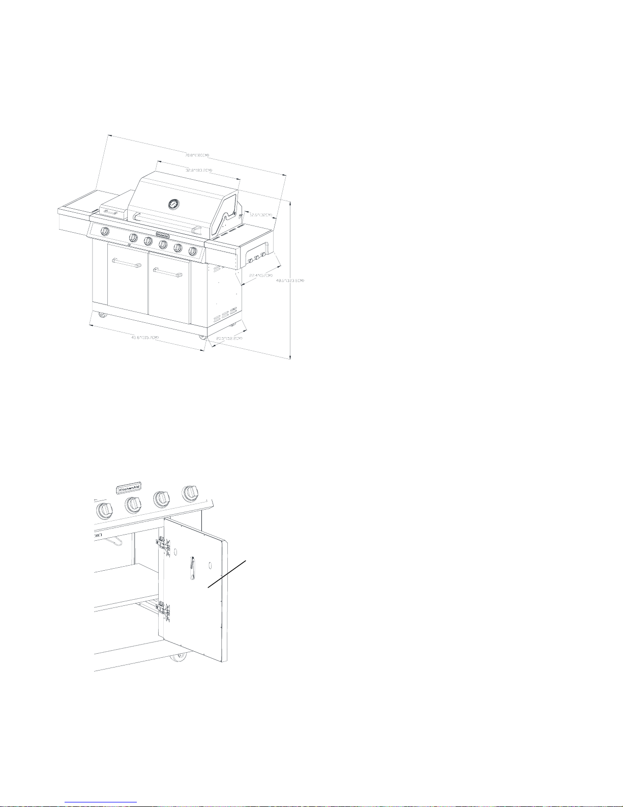
Product Dimension
A. Model/
Serial number plate
Gas Supply Requirements
Observe all govern
ing codes and ordinances.
IMPORTANT: This installation must conform with all local
codes and ordinances. In the absence of local codes,
installation must conform with either the National Fuel Gas
Code, ANSI Z223.1/NFPA54, Natural Gas and Propane
Installation Code, CSA B149.1, Propane Storage And Handling
Code, B149.2, or the Standard for Recreational Vehicles, ANSI
A119.2/NFPA 1192 and CSA Z240 RV Series Recreational
Vehicle Code as applicable.
IMPORTANT: Grill must be connected to a regulated gas
supply. Refer to the model/serial rating plate for information on
the type of gas that can be used. If this information does not
agree with the type of gas available, check with your local gas
supplier.
Gas Conversion:
No attempt shall be made to convert the grill from the gas
specified on the model/serial rating plate for use with a different
gas type without consulting the serving gas supplier. The
conversion kit supplied with grill must be used. See “Gas
Conversions” section for instructions.
Gas Pressure Regulator
The gas pressure regulator supplied with this grill must be used.
The inlet (supply) pressure to the regulator should be as follows
for proper operation:
LP Gas:
Operating pressure: 11" (27.9 cm) WCP
Inlet (supply) pressure: 11" to 14" (27.9 cm to 35.5 cm) WCP
Natural Gas:
Operating pressure: 4" (10.2 cm) WCP
Inlet (supply) pressure: 7" to 14" (17.8 cm to 35.5 cm) WCP
maximum.
Contact local gas supplier if you are not sure about the inlet
(supply) pressure.
A
6
The m
odel/serial number rating plate is located on the
inside of the right cabinet door. See the following
illustration.
20 lb LP Gas Fuel Tank
This grill is equ
ipped for use with a 20 lb LP gas fuel tank (fuel
tank not supplied). A gas pressure regulator/hose assembly is
supplied.
Any brand of 20 lb LP gas fuel tank is acceptable for use with the
grill, provided that it is compatible with the grill’s retention means
(tank tray included).
It is also design-certified by CSA International for local LP gas
supply or for Natural gas with appropriate conversion.
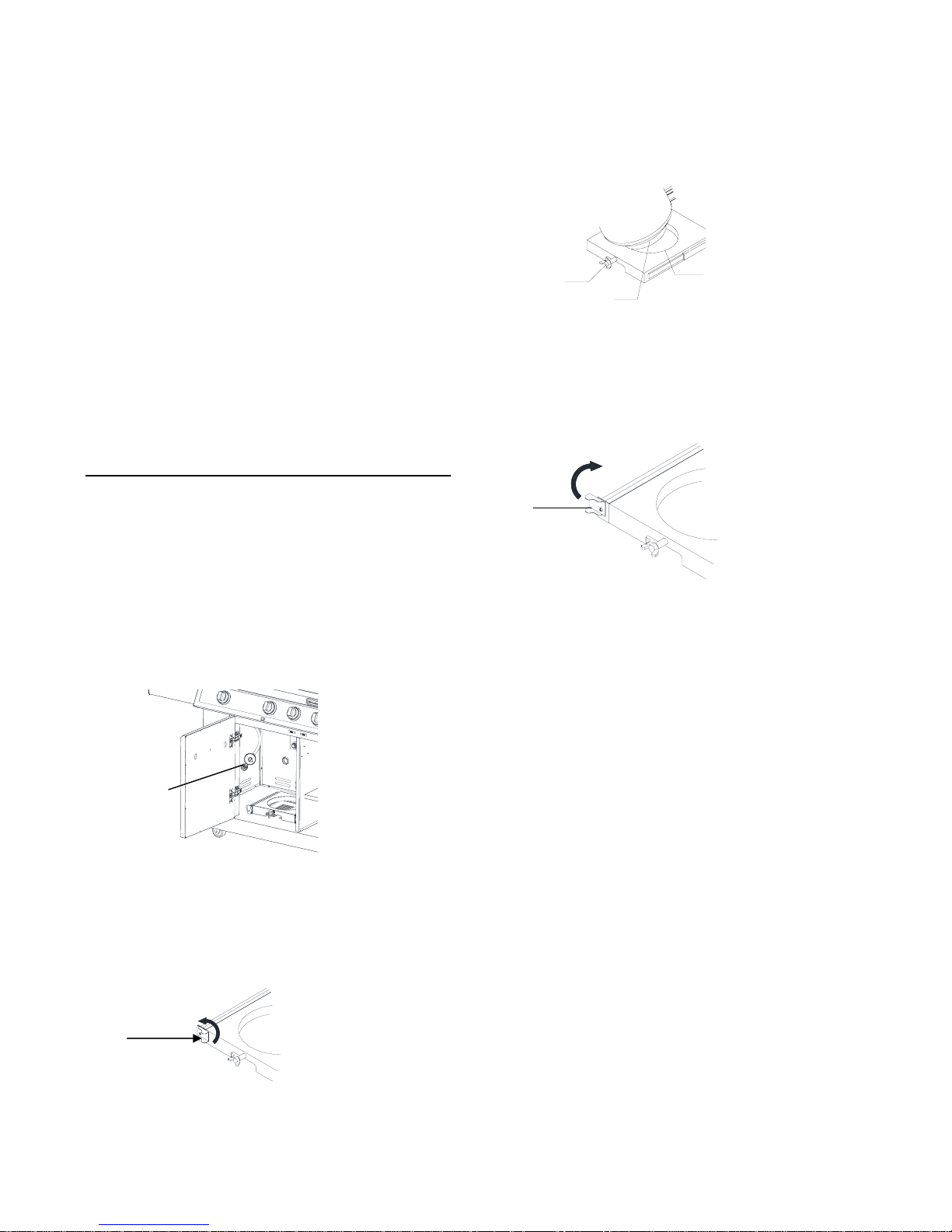
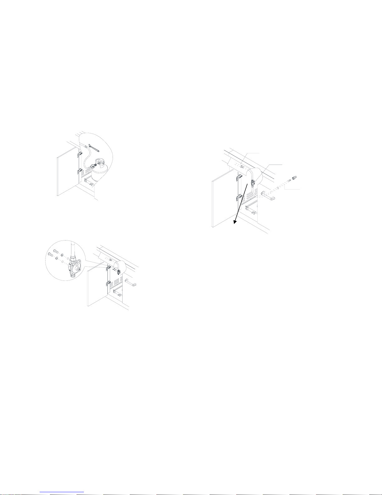
The 20 lb LP gas fuel tank must be mounted and secured.
Door style Tank Tray
1.
Open cabinet doors.
2. Slide the tank tray locking bracket
counterclockwise 90˚ and pull out the tray.
Burner Requirem
ents for High Altitude
Input ratings shown on the model/serial rating plate are for
elevations up to 2,000 ft (609.6 m).
For elevations above 2,000 ft (609.6 m), ratings are reduced at a
rate of 4% for each 1,000 ft (304.8 m) above sea level. Orifice
conversion is required. See “Assistance” section to order.
Gas Supply Line Pressure Testing
Testing above 1/2 psi (3.5 kPa) or 14" (35.5 cm) WCP (gauge):
The grill and its individual shutoff valve must be disconnected
from the gas supply piping system during any pressure testing of
that system at test pressures greater than 1/2 psi (3.5 kPa).
Testing below 1/2 psi (3.5 kPa) or 14" (35.5 cm) WCP (gauge)
or lower:
The grill must be isolated from the gas supply piping system by
closing its individual manual shutoff valve during any pressure
testing of the gas supply piping system at test pressures equal to
or less than 1/2 psi (3.5 kPa).
A. Gas pressure regulator/hose assembly
A
7
3. Pla
ce the 20 lb LP gas fuel tank bottom collar into
the mounting hole in the tank tray.
4. Tighten the locking screw against the bottom collar
of the Natural Gas Conversion 20 lb LP gas fuel tank to
secure.
A.
Tank tray locking bracket
A
5. Slide
the drawer with the 20 lb LP gas fuel tank back into the
cabinet. Turn the tank tray locking bracket clockwise 90˚
to tighten.
A
A. Tank tray l
ocking bracket
Gas Connection Requirements
A. Locking scr
ew
B. Mounting hole
C. Bottom collar
A
C
B
Na
tural Gas Conversion
Conversion must be made by a qualified gas technician. The
qualified Natural gas technician shall provide the Natural gas
supply to the selected grill location in accordance with the
National Fuel Gas Code ANSI Z223.1/NFPA 54 - latest edition,
and local codes. For conversion to Natural gas, the Natural
Gas Conversion Kit supplied with the grill (on some models) or
the Natural Gas Conversion Kit Part Number 710-0003 must
be used. See “Assistance” section for information on ordering.
IMPORTANT: The gas installation must conform with local
codes, or in the absence of local codes, with the National Fuel
Gas Code, ANSI Z223.1/NFPA 54 - latest edition.
Follow instructions for converting to Natural gas in the “Gas
Conversions” section of this manual or the instructions
supplied with Natural Gas Conversion Kit Part Number 710-
0003.
The gas supply line shall be equipped with an approved
shutoff valve. This valve should be located in the same area as
the grill and should be in a location that allows ease of opening
and closing. Do not block access to the shutoff valve. The
valve is for turning on or shutting off gas to the grill.
A. Gas
supply line
B. Shutoff valve “open” position
C. To grill
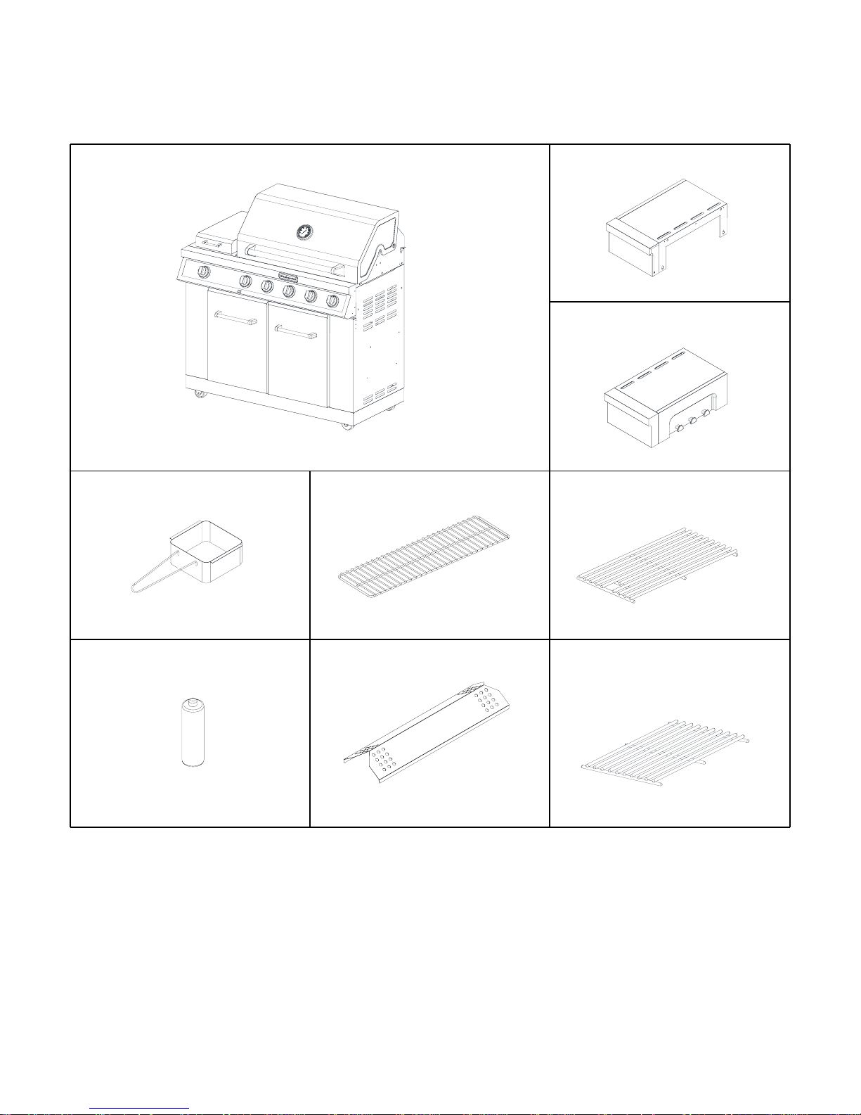
A. Firebox assem
bly-—1pc
D.
Grease cup—1pc
C. Right side shelf—1pc
E. Warming rack—1pc
H. Flame Tamer—5pcs
F. Cooking grid—3pcs
G. Battery—5pc
B. Left side shelf—1pc
I. Side Cooking grid—1pcs
PACKAGE CONTENTS LIST
8

Replacement Parts
9
65
64
66
67
68
69
70
71
72
73
74
77
76
78
75
79
80
53
23
14
15
16
17
56
51
52
55
57
58
59
60
61
62
63
01
02
03
04
02
06
05
07
34
35
36
37
38
40
39
41
08
09
10
12
13
11
18
19
20
21
24
25
26
27
28
29
30
31
32
33
44
45
42
43
46
47
43
48
49
54
50
22
81
a
81
b
81
c
81
d
81
e
81
g
81f
81
NG Co
nversion Kit
11Bottom panel5811Tempered glass fix panel29
Part List
Part
Number
Part (description)
Warranty
Cover
age
Quantity
Part
Number
Part description)
Warranty
Coverage
Quantity
1 Main lid 3 1 30 Tempered glass 1 1
2 Main lid screw 1 2 31 Control knob bezel 1 6
3 Temperature gauge seat 1 1 32 Control knob 1 6
4 Temperature gauge 1 1 33 Light switch 1 1
5 Main lid handle seat, left 1 1 34 Sear burner lid 1 1
6 Main lid handle seat, right 1 1 35 Sear burner lid handle 1 1
7 Main lid handle tube 1 1 36 Sear burner lid hinge 1 2
8 Warming rack 1 1 37 Sear burner cooking grid 3 1
9 Cooking grid with hole 3 3 38 Sear burner 1 1
10 Flame tamer 1 5 39 Sear burner grease tray 1 1
11 Burner Pin assenbly 1 5 40 Sear burner igniter wire 1 1
12 Main burner 10 5 41
Sear burner bowl
assembly
11
13 Main burner igniter wire A 1 1 42 Side shelf, left 1 1
14 Main burner igniter wire B 1 1 43 Hooks 1 6
15 Main burner igniter wire C 1 1 44 Side shelf end cap, left 1 1
16 Main burner igniter wire D 1 1 45 Side shelf front panel, left 1 3
17 Main burner igniter wire E 1 1 46 Side shelf, right 1 1
18 Main lid bracket, right 1 1 47 Side shelf end cap, right 1 1
19 Main lid bracket, left 1 1 48
Side shelf control panel,
right
13
20
Main burner bowl
assembly
Nonreplaceable
1 49 Back panel 1 1
21 Front baffle 1 1 50 Rubber grommet 1 1
22 Main gas valve 1 5 51 Firebox support 1 1
23 Searing gas valve 1 1 52 Heat shield, left 1 1
24 Main manifold 1 1 53 Electronic igniter modular 1 1
25 Regulator LP 1 1 54 Side panel, right 1 1
26 Control panel light 1 1 55 Heat shield, right 1 1
27 Main control panel 1 1 56 Grease box 1 1
28 Logo 1 1 57 Clapboard 1 1
10
1
PVC cover
11
Gas tan
k tray slide
bracket, left
75
Part
Number
Part (description)
Warranty
Coverage
Quantity
Part
Number
Part (description)
Warranty
Coverage
Quantity
59 Swivel caster with brake 1 1 76 Gas tank tray slide 1 1
60 Swivel caster 1 1 77 Tank bolt 1 1
61 Casters 1 2 78 Gas tank tray slide bracket, right 1 1
62
Lighting rod 1 1 79 Gas tank tray 1 1
63
Lighting rod cover 1 1 80 Electronic igniter modular cover 1 1
64
Door, right 3 1 81 NG conversion Kit
NG conversion kit sold
separately as a set
65
Door, left 3 1 81a NG regulator assembly for NG unit 1
66
Door handle tube 1 2 81b
NG Gas Hose with Quick
Connector assembly for NG unit
1
67 Door handle seat 1 4 81c 6mm Nut Driver 1
68 Side panel, left 1 1 81d Hex Wrench 1
69 Center panel 1 1 81e 6mm Wrench 1
70 Cart frame 1 1 81f Flat Washer 2
71 Door magnet 1 2 81g Truss Head Screw with Lock 2
72 Battery box 1 1
Preassembly hardware pack
1
73 Door hinge 1 4
NG orifice pack
1
74 Tank tray block piece 1 1
Manual
1
11
INSTALLATI
ON INSTRUCTIONS
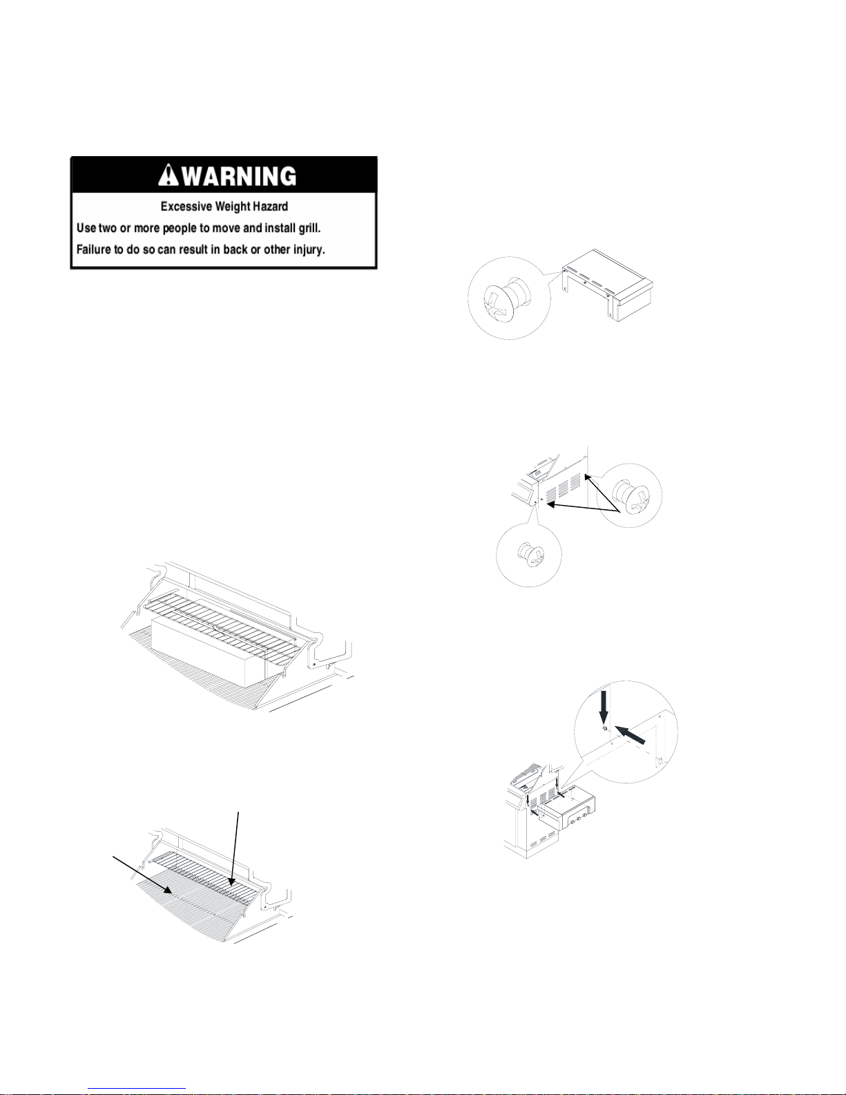
Freestanding Outdoor Grill Installation
Unpac
k Grill
1. Remove all packaging materials and remove grill from the
shipping base.
2. Move grill close to desired outdoor location.
3. Open the grill hood.
Remove Packaging Material Inside the Grill
4. Remove the
grill grates (F).
5. Remove warming rack (E) on brackets as
shown.
F
E
A
ttach right side shelf
IMPORTANT: This step is meant to help with the
installation, but do not depend solely on the two
screws to hold the weight of the side shelf.
1. Unpack right side shelf (
C).
2. Loosen and remove 3 screws on left side shelf.
3. Loosen but do not remove the 2 screws on the side panel (A),
remove the screw lock on the main control panel (B).
A
B
4. Align slots on the side shelf with the loosened scre
ws. Hook
the side shelf onto the two loosened screws and let the shelf
slide down so the screws are in the narrow neck of the slots.
1. Use a utility knife to cut straps and packing tape to open
box from top and remove the boxes.
2. Remove the warming shelf and grill grates from inside the
grill and remove the package inside the firebox.
3. Remove foam block and wrap from inside the grill.
12
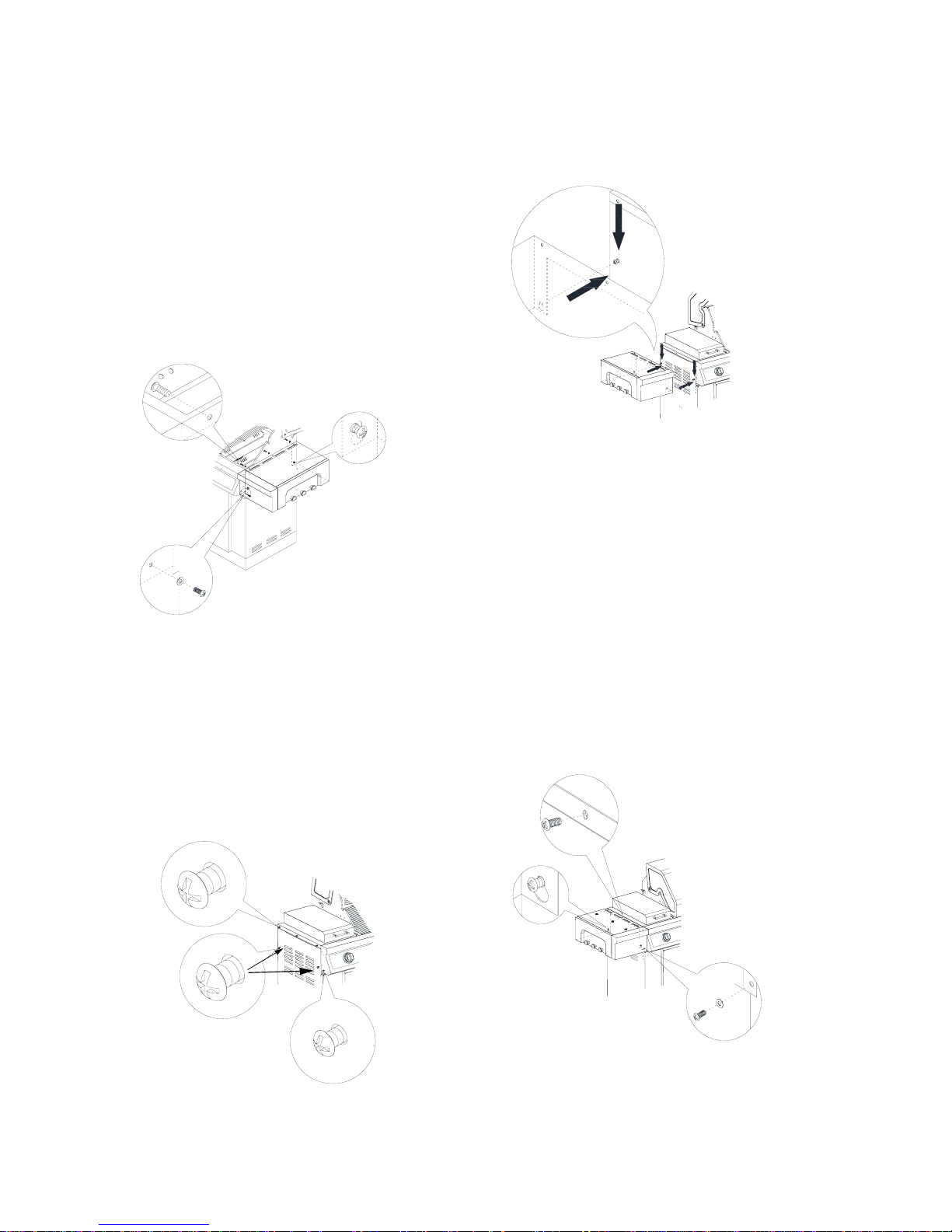
Attach Left Si
de Shelf
1. Unpack left side shelf (B).
2. Loosen but do not remove the 2 screws on the side
panel (A). Remove the 3 screws on the side panel (B).
Remove the screw on main control panel (C).
IMPORTANT: This step is meant to help with the
installation, but do not depend solely on the two
screws to hold the weight of the side
shelf.
A
B
C
13
5
. Attach the top of the side shelf to the grill firebox
by inserting three screws into the side shelf
from inside the grill firebox and tighten. See (A) below.
6. Attach the bottom of the side shelf to the side panel of
the grill by tightening the two screws inserted in the
keyhole slots in Step 3. See (B) below.
7. Attach the side shelf to the control panel by inserting
screw which was removed from step 3 and tighten,
A
B
C
3. Align t
he bottom keyhole slots on the side shelf with
the loosened screws. Hook the side shelf onto the two
loosened screws and let the shelf slide down so the
screws are in the narrow neck of the slots.
A
B
C
4
. Attach the top of the side shelf to the searing side burner
side by inserting three screws from side shelf side and
tighten. See (B) below.
5. Attach the bottom of the side shelf to the side panel of
the grill by tightening the two screws inserted in the
keyhole slots in Step 2. See (A) below.
6. Attach the side shelf to the control panel by
inserting the screw which was removed from step 3
and tighten. See (C) below.
see (C) below.
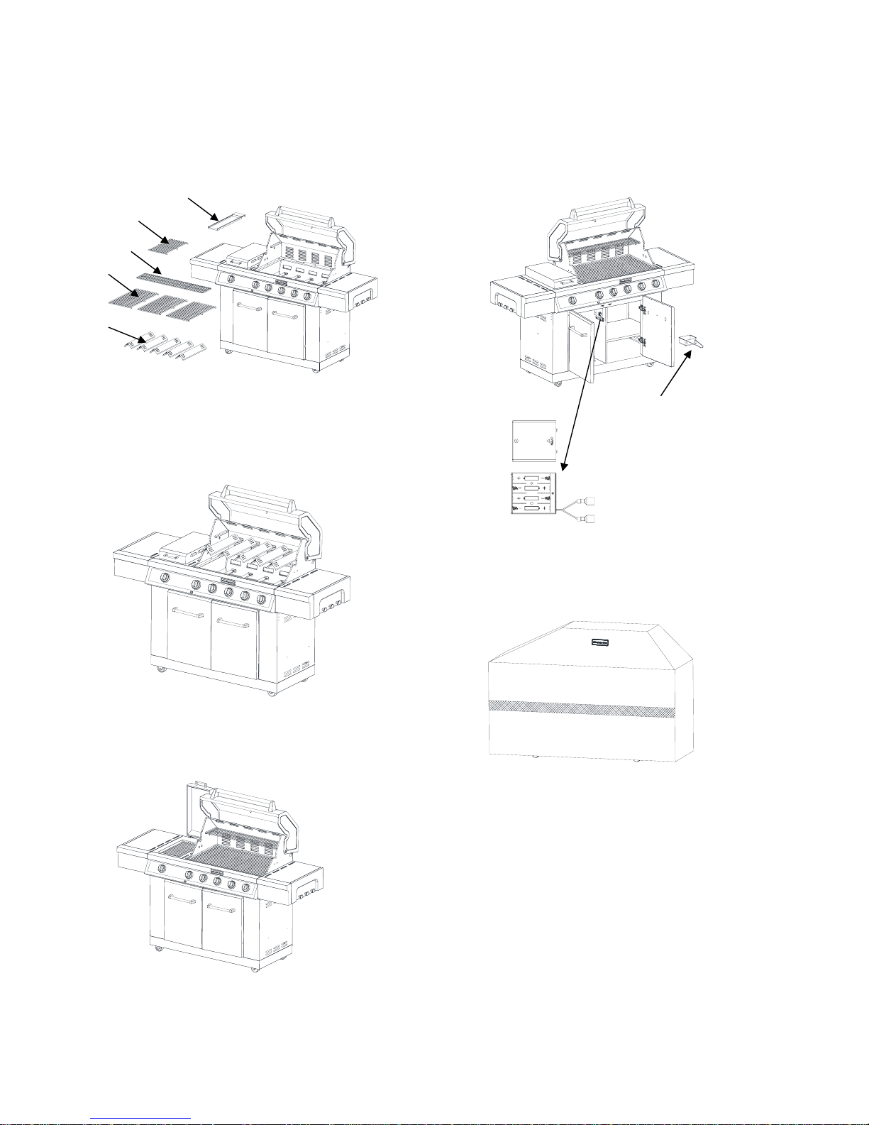
S
pare Parts Assembly
1. Unpack the searing burner grease cup, 5 flame tamer (H), 3
cooking grid (F), warming rack (E), and searing side burner
cooking grid (I).
2. Put the flame tamers on the indentations in firebox.
3
. Then put on the cooking grid and warming rack
and searing side burner grids.
4. Open the cart door and place the grease cup between the
grease cup bracket.
5. Slide out battery box cover which is located on cart central
panel left side. Put 4 batteries which are packed in manual bag,
into battery box. Reinstall the battery box.
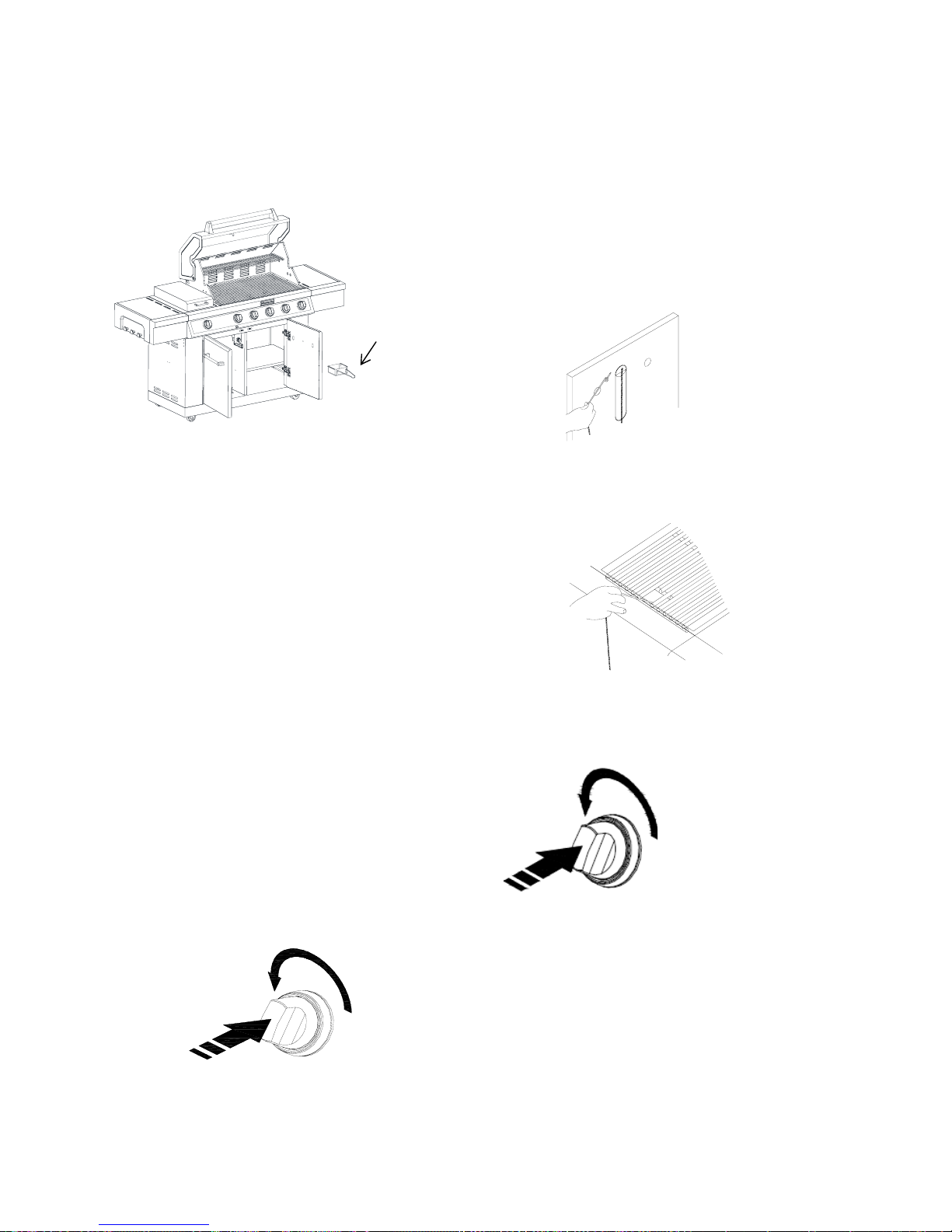
Igniter Battery Assembly
1. Un
screw igniter button cap counterclockwise to remove.
2. Place the battery in, negative end first, and screw the
igniter button cap clockwise.
Grease c
up
F
E
I
H
Battery box
Battery box
cover
A.
“AA”
size
d battery
B. Igniter cap
Cover y
our grill
Allow grill to cool down and cover grill when not in use.
14
Sering burner grease cup
Ma
ke Gas Connection
NOTE: If grill is to be convert
ed to Natural gas, follow
instructions in the “Gas Conversions” section.
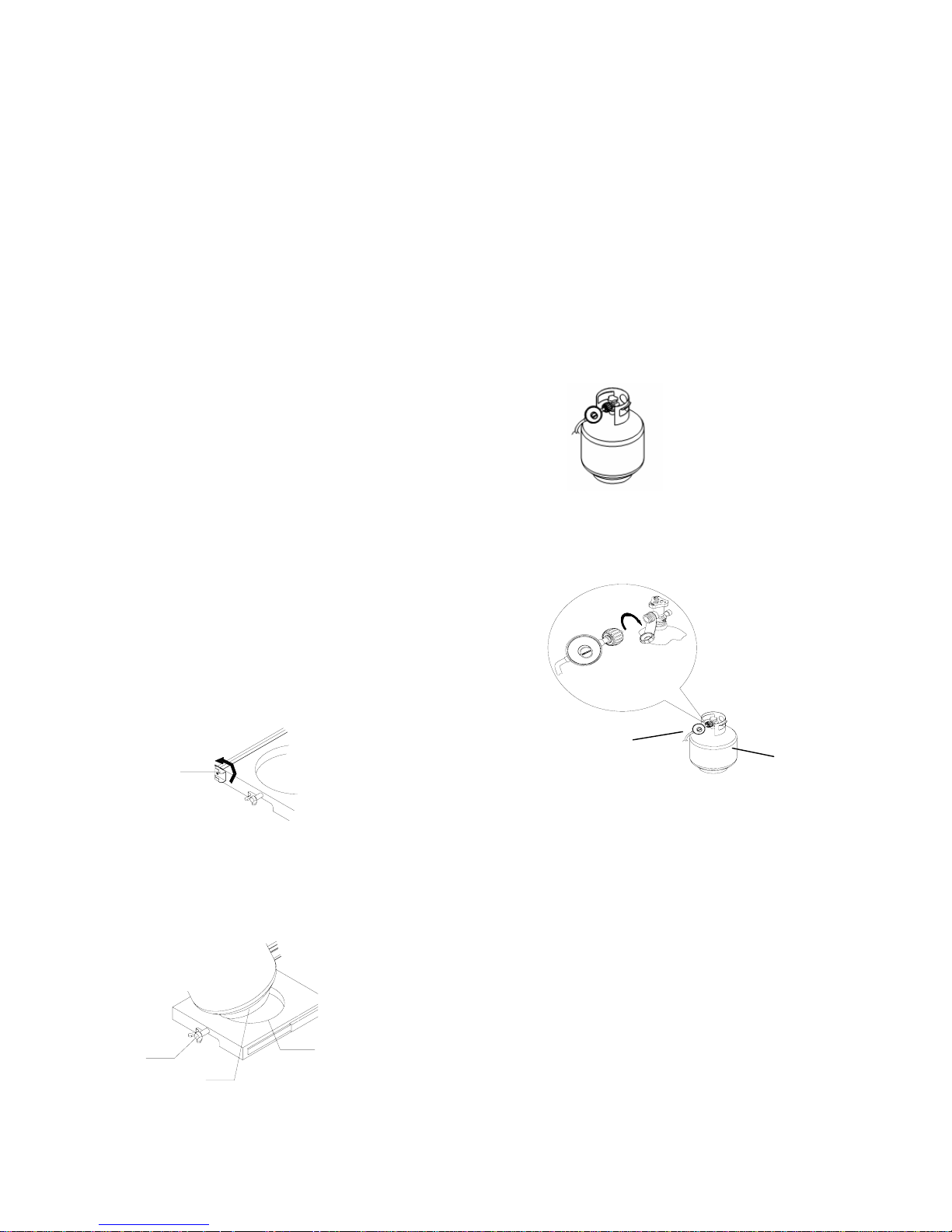
20 lb LP Gas Fuel Tank
To Connect the 20 lb LP Gas Fuel Tank:
1. Check that the 20 lb LP gas fuel tank is in the “Off”
position. If not, turn the valve clockwise until it stops.
2. Check that the 20 lb LP gas fuel tank valve has the proper
type-1 external male thread connections per ANSI Z21.81.
3. Check that the burner control knobs are in the “Off”
position.
4. Remove any debris and inspect the valve connections,
port, and gas pressure regulator/hose assembly for damage.
NOTE: Always keep the LP cylinder at 90° (upright)
orientation to provide vapor withdrawal.
5. Using your ha
nd, turn the gas pressure regulator/hose
assembly clockwise to connect to the 20 lb LP gas fuel tank
as shown.
Hand tighten only. Use of a wrench could damage the quick
coupling nut.
A. Gas pres
sure regulator/hose assembly
B. 20 lb LP gas fuel tank
A
B
Make su
re that the cylinder valve connection device
properly mates with the connection device attached to the
inlet of the pressure regulator.
6. Open the tank valve fully by turning the valve
counterclockwise. Wait a few minutes for gas to move
through the gas line.
7. Before lighting the grill, test all connections by brushing
on an approved noncorrosive leak-detection solution.
Bubbles will show a leak.
8. If a leak is found, turn the tank valve off and do not use
the grill. Contact a qualified gas technician to make repairs.
9. Go to “Check and Adjust the Burners” section.
LP Gas:
IMPORTANT: A 20 l
b LP gas fuel tank must be purchased
separately.
IMPORTANT: The gas pressure regulator/hose assembly
supplied with the grill must be used. Replacement gas pressure
regulator/hose assembly specific to your model is available from
your outdoor grill dealer.
Door Style Tank Tray
1. Open cabinet doors.
2. Slide the tank tray locking bracket counterclockwise 90º
and pull out the tray.
A. Tank tray locking bracket
A
3
. Place the 20 lb LP gas fuel tank bottom collar into the
mounting hole in the tank tray.
4. Tighten the locking screw against the bottom collar of
the 20 lb LP gas fuel tank to secure.
A
B
C
A. Locking scr
ew
B. Mounting hole
C. Bottom collar
15
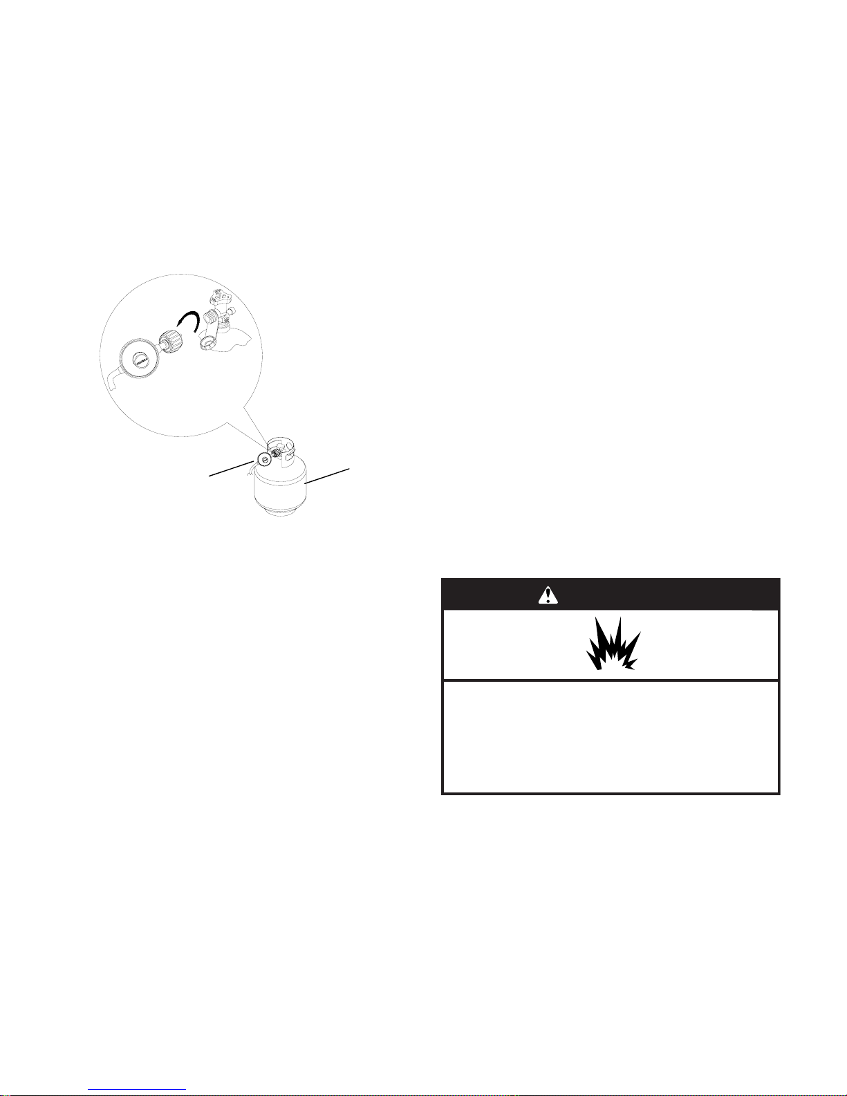
T
o Disconnect the 20 lb LP Gas Fuel Tank:
1
. Check that the burner control knobs are in the “Off” position
and the grill is cool.
2. Check that the 20 lb LP gas fuel tank is in the “Off” position. If
not, turn the valve clockwise until it stops.
3. Using your hand, turn the gas pressure regulator/hose
assembly counterclockwise to disconnect to the 20 lb LP gas fuel
tank as shown.
Hand loosen only. Use of a wrench could damage the quick
coupling nut.
A. Gas pressure regulator/hose assembly
B. 20 lb LP gas fuel tank
A
B
4
. Place dust cap on cylinder valve outlet whenever the cylinder is
not in use. Only install the type of dust cap on the valve outlet that
is provided with the cylinder valve. Other types of caps or plugs
may result in leakage of propane.
16
GAS CONVERSION
Tools and Parts for Gas Conversion
Ga
ther the required tools and parts before starting installation.
Read and follow the instructions provided with any tools listed
here.
Parts supplied
Natural gas orifices
Parts needed
Natural gas conversion kit Part Number 710-0003. See
“Assistance” section to order. The conversion kit includes:
Natural gas regulator 4" W.C. (marked “Natural Gas
Regulator”)
10 ft (3.0 m) Natural gas hose with quick connector
5.9" (150 mm) Natural gas regulator hose
6 mm nut driver
6 mm wrench
Hex key
IMPORTANT: Gas conversions must be done by a qualified
installer. Before proceeding with conversion, shut off the gas supply
to the appliance.
Tools needed
Phillip screwdriver
Pipe Wrench
Adjustable wrench
6 mm socket and
wrench or 6 mm nut driver
Thin flat-blade
screwdriver
Pliers
Pipe thread sealant
certified for LP gas
WARNING
Explosion Hazard
Use a new CSA International approved “outdoor”
gas supply line.
Securely tighten all gas connections.
Failure to do so can result in death, explosion, or fire.
Install a shut-off valve.
1. A combinat
ion of pipe fittings must be used to connect the grill
to the existing gas line.
The 10 ft (3.0 m) PVC flexible gas supply hose design
certified by CSA must be used.
Pipe-joint compounds suitable for use with Natural gas
must be used. Do not use Teflon®+ tape.
There must be a certified manual shut-off valve in the gas
supply line near the grill for easy access.
2. Connect the brass connector on one end of the 10 ft (3.0 m)
PVC flexible gas supply hose to the Natural gas pressure
regulator.
3. Connect the quick connector on the other end of the
10 ft (3.0 m) PVC flexible gas supply hose to the rigid Natural
gas supply pipe.
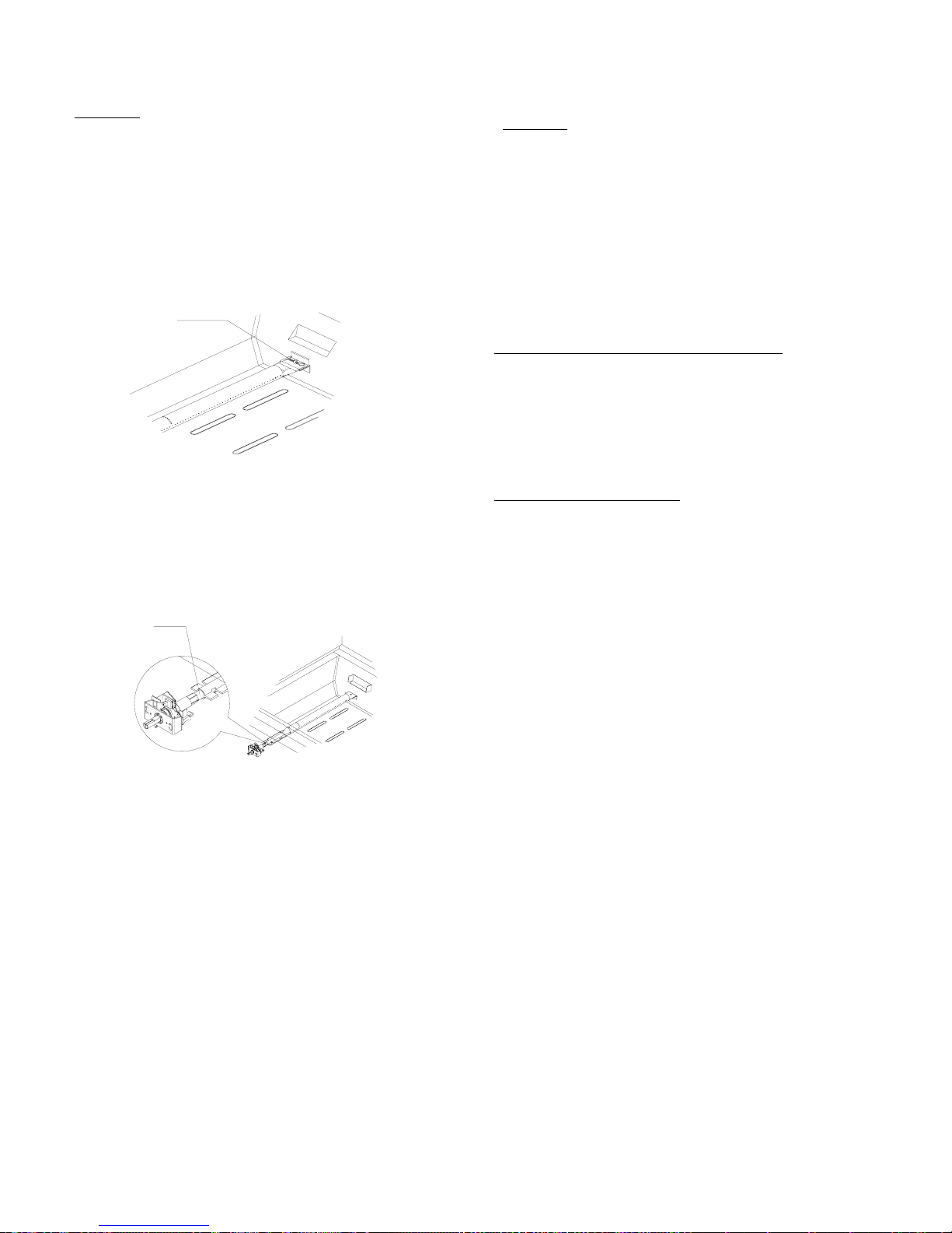
6. Use an adjustable wrench to install the Natural gas
regulator hose to the manifold and secure. Attach the
Natural gas regulator to the side panel inside the grill cart
with the two screws that are pre-assembled on the
regulator.
Conversion from LP Gas to
Natural Gas
1. Turn of
f the main gas supply valve.
2. Disconnect 20 lb LP gas fuel tank (if present).
3. Turn off all burner control valves.
4. Remove the 20 lb LP gas fuel tank (if present) from the grill cart.
5. Use an adjustable wrench to remove the LP regulator from the
manifold.
Installation of the regulator
Make Gas Connection
† ®Teflon is a registered trademark of E.I. Du Pont De Nemours
and Company.
A. Manifold
B. Left side panel
C.10 ft. (3.0 m) PVC gas hose
D. Natural gas pressure regulator/hose assembly
A
C
D
B
17
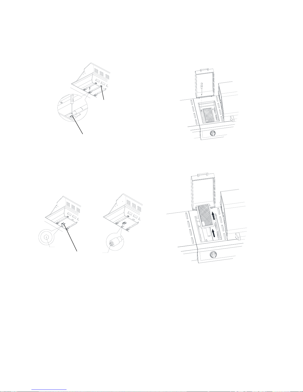
Change Grill
Main Burner Valve Orifices
3. Use a 6 mm socket and wrench or 6 mm nut driver to remove
the brass orifice from the end of gas valve. The main burner
orifice is located behind the LP orifice, so no additional orifice
needs to be installed.
A. Main burner orifice
IMPORTANT: Check that the orifice is properly installed inside of the
burner opening.
4. Reinsert the burner and reattach using the screw and cotter clip
previously removed. Repeat the procedure for each main burner.
5. Position the igniters so they are 1/4" (6.0 mm) away from each
burner.
1. Remove the grates and flame tamers.
2. Remove 1 screw and cotter clip that hold the burner in place. Set
the screw and clip aside. Remove the burner from the grill by lifting
the burner out.
Change the Sear Burner Orifices
1.
Remove the 2 screws securing the igniter and remove
the igniter from the side burner.
2. Remove the searing side burner screws. Set the screws
and cover aside.
18
A
B
A. Screw
B. Cotter Cl
ip
or
ifice
orifice
A

Adjust High Flame Setting Screw
2
. Use a flat-blade screwdriver to turn the high flame
setscrew counterclockwise approximate 90 degree.
3.
Lift the searing side burner out of the grill.
4. Use 6 mm socket wrench or 6 mm nut driver to remove the
orifice. Replace with the Natural gas orifice.
IMPORTANT:
Check that the orifice is properly installed inside of the
valve.
5. Reinstall the searing side burner Make sure that the igniter is out
of the way to allow proper positioning of burner. Use Phillips
screwdriver to attach the mounting screws.
6. Use Phillips screwdriver to reattach the igniter and searing side
burner plate.
7. Reinstall searing side burner cover. Use Phillips screwdriver to
attach mounting screws.
8. Open the manual shutoff valve in the gas supply line. The valve is
open when the handle is parallel to the gas pipe.
9
. Test all connections using an approved noncorrosive
leak-detection solution. Bubbles will show a leak. Correct
any leak found.
Whe
n converting from LP to Natural gas, you will need to adjust
the high flame setting screw for ideal burner flame height.
1. Remove each control knob for the main burners and side burner
3. Check that burner operates at the new high flame setting.
It may be necessary to adjust the screw setting slightly more to
get the ideal burner flame height.
orifice
o
rifice
19
A. Closed
valve
B. Open valve
In the last page of the Use and Care Guide, writer “ Converted
to Natural Gas.” Also record the conversion date and the
technician/company that performed the conversion.
Note: Place LP gas parts in plastic parts bag for future use and
keep with pack containing literature.
1. The appliance nameplate is located inside the grill cabinet
on the left –hand cabinet side. With a permanent marker,
check the box next to “Natural gas” and mark through “LPPropane.”
Record Conversion
Check and Adjust the Burners
Th
e burners are tested and factory-set for most efficient operation.
However, variations in gas supply and other conditions may make
minor adjustments to air shutter or low flame setting necessary.
It is recommended that a qualified person make burner adjustments.
Checking and adjusting the grill burner flames requires removing
the grates and flame tamers.
A. Clip
6
. If flame is yellow (not enough air), turn air shutter adjustment
screw counterclockwise.
If flame is noisy or lifts away from burner (too much air), turn air
shutter adjustment screw clockwise.
Adjustment should be made clockwise or counter clockwise from
1/8” (3.2 mm) to ¼” (6.4 mm).
7. Replace gas burner, sear plates and grates.
8. Light grill using information in the “Outdoor Grill Use” section.
See “Burner Flame Characteristics
A. Air shutter adjustment screw
A
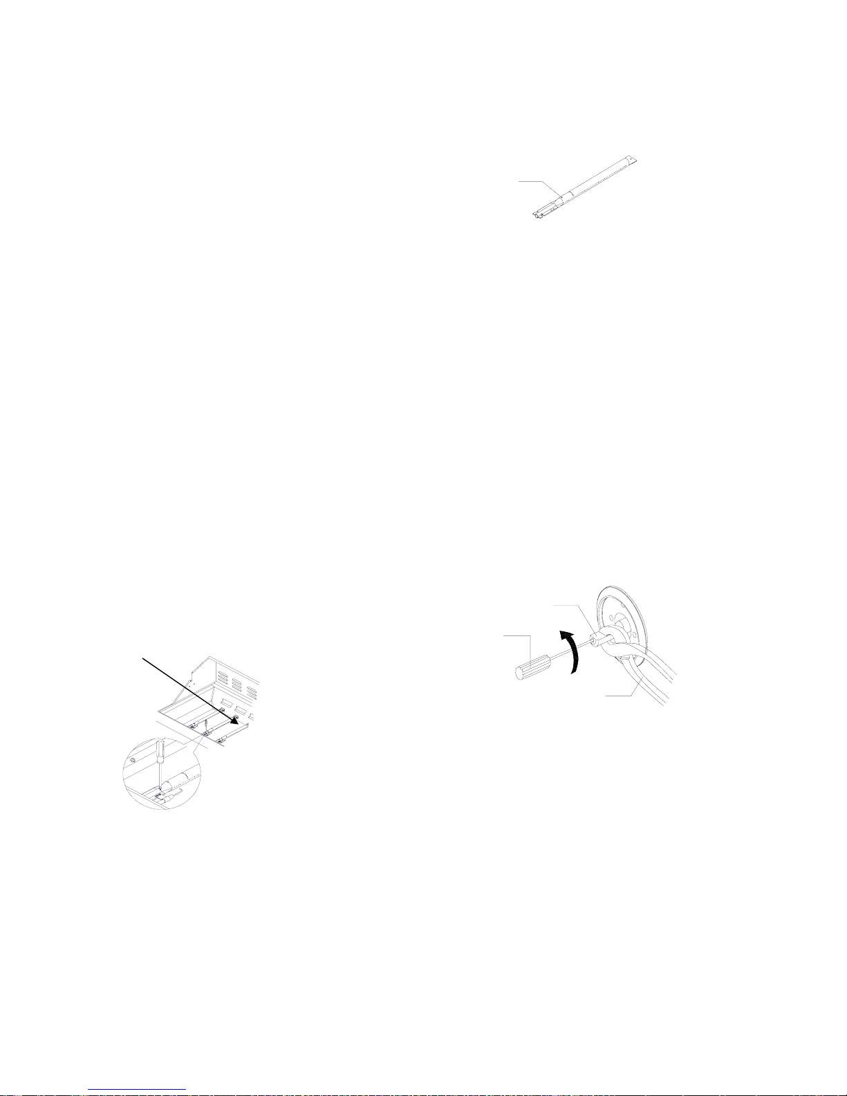
If
flame goes out on the “LOW” setting, the low flame setting
must be adjusted.
1. Turn off the valve and wait until grill and burners are cold.
2. Remove grill grates and flame tamers.
3. Light grill using information in the “Outdoor Grill Use” section.
4. Turn burner to its lowest setting.
5. Remove each control knob for the main burners and side
burner by loosening the setscrew with the hex key.
6. Hold valve stem with pliers and insert a small flat-blade
screwdriver into the shaft.
7. Watch the flame and slowly turn the screwdriver
counterclockwise.
8. Adjust flame to minimum stable flame.
A. Valve stem
B. Small flat-blade screwdriver
C. Pliers
A
B
C
The flames
of the grill burners and side burners (on some models)
should be blue and stable with no excessive noise or lifting (LP gas
flames will have a slightly yellow tip). A yellow flame indicates not
enough air. If flame is noisy or lifts away from the burner, there is
too much air. Some yellow tips on flames when the burner is set to
HIGH setting are acceptable as long as no carbon or soot deposits
appear. The flames should be approximately 1" (2.5 cm) high.
Burner Flame Characteristics
Low Flame Adjustment
9
. Replace the control knob and turn off the burner.
10. Repeat steps 3 through 9 for each burner if needed.
11. Replace the flame tamers and grates after the burners have
cooled.
Check that burners are not blocked by dirt, debris, insect nests,
etc., and clean as necessary. If they are clean, adjust air shutters
as needed.
IMPORTANT: Before adjusting air shutters, let burners cold
down completely. To Adjust:
1. Light grill using information in the “Outdoor Grill Use” section.
2. Observe flame to determine which burners need adjustment
and how the flame is acting.
3. Turn off the valve and wait until grill and burners cold
completely.
4. Remove grill grates and flame tamers.
5. Remove the 1 screw and cotter pin that hold the burner in
place. Remove gas burner from the grill.
A
20
OUTDOOR GRILL USE
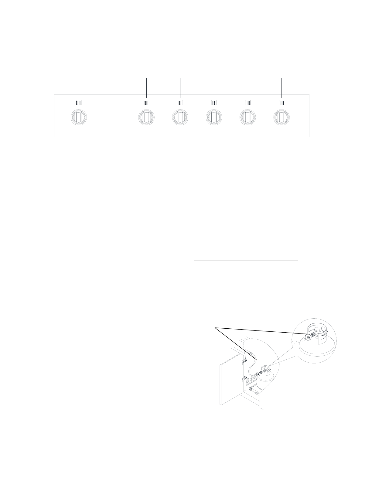
A. Se
ar burner control knob B. Main burner control knob C.
Main
burner control knob
D. Main burner control knob E. Main burner
con
trol knob
F
. Main burner control knob
Ins
pect the gas pressure regulator/hose assembly before
each use.
1. Open the cabinet door.
2. Inspect the gas pressure regulator/hose assembly for
cuts, abrasions, or excessive wear.
3. If necessary, replace the gas pressure regulator/hose
assembly before using the grill.
Contact the dealer and use only replacement hoses
specified for use with the grill.
This manual covers several different models. The grill you have purchased may have some or all of the features listed. The locations
and appearances of the features shown here may not match those of your model.
Control Panel
Using Your Outdoor Grill
Inspec
t the LP Gas Fuel Tank Supply Hose
A. Gas pres
sure regulator/Hose assembly
AB
CDEF
A
21
22
Prepare the Grill for Lighting
1. For using a
20 lb LP gas fuel tank: Slowly open the tank valve.
NOTE: If flow limiting device activates, your grill may not light. If
your grill does light, the flames will be low and will not heat
properly. Turn tank valve and all control knobs off and wait 30
seconds. After shutting off the tank, very slowly open tank valve
and wait 5 seconds before lighting.
2. For outdoor grills using gas supply source other than a 20 lb
LP gas fuel tank:
Open the manual shutoff valve in the gas supply line. The valve
is open when the handle is parallel to the gas pipe.
Lighti
ng the Grill
Manually Lighting the Grill
4. Strike the match to light it.
5. Guide the lit match between the grill grate.
6. Push in and turn the burner knob to IGNITE/HIGH or
IGNITE/ON for the burner closest to the lit match. The burner will
light immediately. When burner is lit, turn knob to desired setting.
7. Repeat steps 2 trough 6 for each main burner.
8. Remove match and replace manual lighting extension inside
the cabinet door.
IMPORTANT:
If burner does not light immediately, turn the burner knob to OFF
and wait 5 minutes before relighting. If any burners do not light
after attempting to light them manually, contact the Customer
Service Center. See the “ Assistance or Service” section.
1. Open the hood completely. Do not light burners with the hood
closed.
2. Make sure control knobs are turned to OFF. The grease cup
must be in place.
Turn the Gas Supply On
1. Open the hood completely. Do not light burners with the hood
closed.
2. Do not lean over the grill.
3. Select the burner you want to light. Push in and turn the grill
burner control knob to IGNITE/HIGH or IGNIE/ON, while
continuing to hold it in.
4. You will hear the “snapping” sound of the spark. When burner
is lit, release the knob. Turn knob to desired setting.
5. Repeat for each of the other burners as needed.
IMPORTANT: If burner does not light immediately, turn the
burner knob to OFF and wait 5 minutes before relighting.
1. Open the hood completely. Do not light burners with hood
closed.
2. Do not lean over the grill.
3. Remove the manual lighting extension (see following
illustration) and attach a match to the split ring.
Grease
Cup
Using Your Searing Side Burner
Infrared grilling produces intense heat which quickly sears the
meat.
Using Your Searing Side Burner
Infrared grilling produces intense heat which quickly sears the
meat. Searing locks in flavor and juices while allowing the outer
surface to absorb smoke and food aroma that is produced as
grease and drippings are vaporized by the burner. The result is a
crisp, flavorful outside with a tender, juicy inside.
1. Preheat the infrared sear burner for 5 minutes.
2. Ensure that meats are fully thawed and that all excess fat is
trimmed
away prior to grilling.
3. Leave the burner set to HI when placing food on the grill to sea
4. Use the sear burner to sear meat 1 to 2 minutes on each side,
then move the meat to the main grill cooking surface to finish
grilling to he desired doneness.
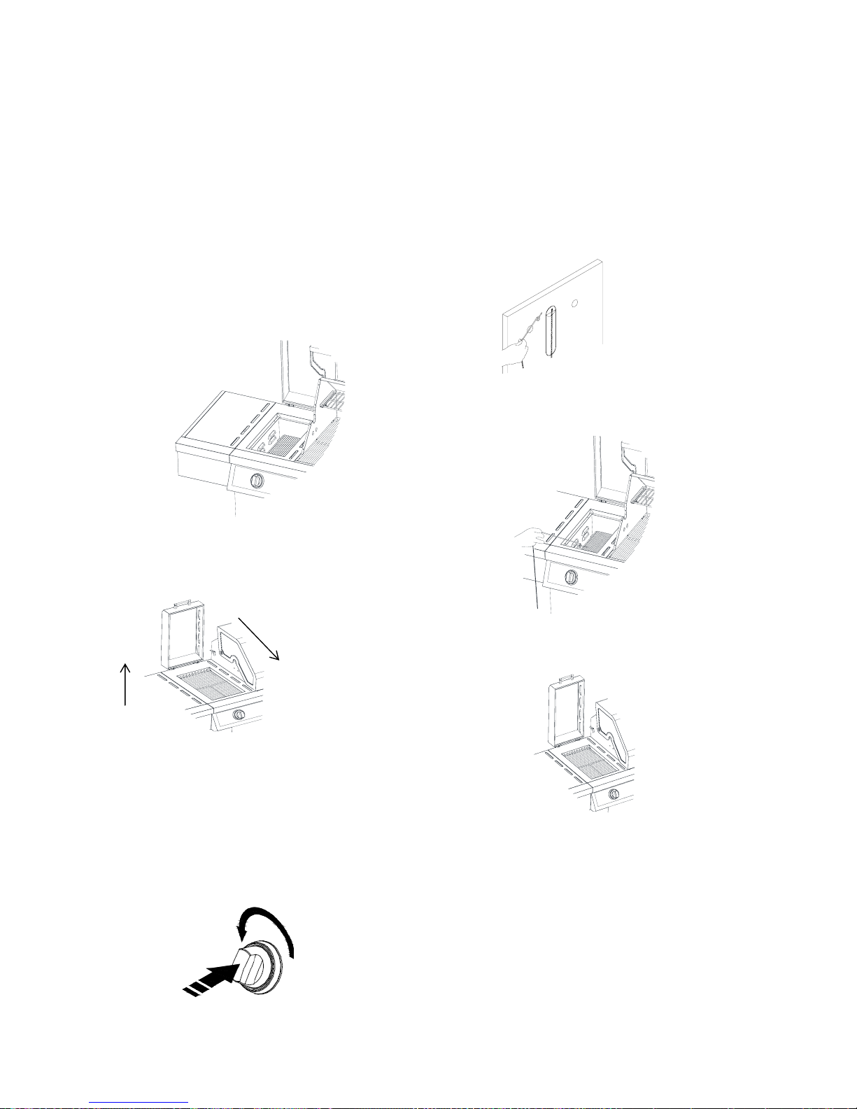
IMPORTANT: It is recommended that the sear side burner lid be
raised when the burner is in use to eliminate the possibility of
increased lid and handle temperatures.
1. To close the searing side burner lid, first lift up the lid to release
the lock then lower it to the closed position.
1
2
Lighting the Searing Side Burner
1. Remove the searing side burner cover. Do not light
burners with the
cover on.
2. Do not lean over the grill.
3. Push in and turn the control knob to IGNITE/ON and hold
in. You
will hear the “snapping” sound of the spark. When burner is
lit, release the knob. Turn knob to desired setting.
Manually Lighting the Searing Side Burner
1. Remove the searing side burner cover. Do not light
burners with the
cover on.
2. Do not lean over the grill.
3. Remove the manual lighting extension (see following
illustration)
and attach a match to the split ring.
4. Strike the match to light it.
IMPORTANT: If burner does not light immediately, turn the burner
knob to OFF and wait 5 minutes before relighting.
5. Hold the lit match close to the searing side burner.
6. Push in and turn the burner knob to IGNITE/ON for the burner
closest to the lit match. The burner will light immediately. When
burner is lit, turn knob to desired setting.
7. Repeat steps 3 through 6 for each burner.
8. Remove match and replace manual lighting extension on the
right side panel.
IMPORTANT:
If burner does not light immediately, turn the burner knob to OFF
and wait 5 minutes before relighting. If any burners do not light
after attempting to light them manually, contact the Customer
Service Center. See the “Assistance” section.
23

Direct Heat
Cooking by direct heat means the food is placed on grill
grates directly above lighted burners. Hood position can be
up or down. If hood is in the up position, total cooking times
may be longer. Direct heat sears the food. Searing is a
process that seals natural juices in food by cooking with
intense heat for a short period of time. While juices stay
inside, the outside is browned with a
flavorful grilled coating.
Indirect Heat
For best results, do not select the indirect heat cooking
method when it is windy.
Cooking by indirect heat means the food is placed on the
grill grate above an unheated burner, allowing heat from
lighted burner(s) on either side to cook the food.
If possible, turn on 2 burners. Cook with the hood down. This
will shorten the cooking time.
Cooking Methods
TIPS FOR OUTDOOR GRILLING
Before Grilling
■ Thaw food items before grilling.
■ Preheat grill on high (use all grill burners) 10 minutes. The
hood must be closed during preheating. Preheating provides
the high heat needed to brown and seal the juices.
■ Shorten the preheat time when grilling high-fat cuts of meat
or poultry, such as chicken thighs. This will help reduce
flare-ups.
■ Lightly oil the grill grates or the food when cooking low-fat
cuts of meat, fish or poultry, such as lean hamburger patties,
shrimp or skinless chicken breasts.
■ Using too much oil can cause gray ash to deposit on food.
■ Trim excess fat from meats prior to cooking to reduce
flare-ups.
■ Make vertical cuts at 2" (5 cm) intervals around the fat edge
of meat to avoid curling.
■ Add seasoning or salt only after the cooking is finished.
■ It may be necessary to lower the heat setting for foods that
cook a long time or are marinated or basted in a sugary sauce.
■ If using a high flame, add barbecue sauce only during the last
10 minutes of cooking to avoid burning the sauce.
■ The degree of doneness is influenced by the type of meat, cut
of meat (size, shape and thickness), heat setting selected, and
length of time on the grill.
■ Cooking time will be longer with an open grill cover.
During Grilling
■ Turn foods only once. Juices are lost when meat is turned
several times.
■ Turn meat just when juices begin to appear on the surface.
■ Avoid puncturing or cutting the meats to test doneness. This
allows juices to escape.
24

Knobs have High, Medium and Low settings for flame
adjustment.
Heat settings indicated are approximate.
Grilling times are affected by weather conditions.
When 2 temperatures are listed, for example: Medium to
Medium-Low, start with the first and adjust based on cooking
progress.
Cooking times may vary from chart times depending on the
type of fuel, Natural or LP gas.
FOOD COOKING METHOD/
BURNER SETTING
INTERNAL TEMP. TIME
(total minutes)
SPECIAL INSTRUCTIONS
Beef
Hamburgers ½" (1.3 cm) to
¾
" (1.9 cm) thick
DIRECT Medium Medium (160°F/71°C) 10-15 Grill, turning once.
Roasts
Rib Eye, Sirloin
INDIRECT
Medium/OFF/Medium
Med-Rare (145°F/63°C)
to Medium (160°F/71°C)
32-40 per lb
(12-15 per kg)
Tent with foil first 45-60
minute; of cooking time.
Steaks, 1" (2.5 cm)
Porterhouse, Rib, T-bane,
Top Loin, Sirloin
DIRECT Medium Med-Rare (145°F/63°C)
to Medium (160°F/71°C)
11-16 Rotate steaks Vi turn to create
criss-cross grill marks.
Steaks, 1½" (3.8 cm)
Porterhouse, Rib, T-bane,
Top Loin, Sirloin
DIRECT Medium Med-Rare (145°F/63°C)
to Medium (160°F/71°C)
18-25
Top Round or Shoulder/
Chuck (London Broil) 1½"
(3.8 cm) thick
DIRECT Medium Med-Rare (145°F/63°C)
to Medium (160°F/71°C)
22-29
Flank, ½" (1.3 cm) thick DIRECT Medium Med-Rare(145°F/63°C) 11-29
Pork
Chops,
1" (2.5 cm)
1½ " (3.8 cm) thick
DIRECT Medium to
Med-Low
Medium (160°F/71 °C) 12-22
30-40
Ribs
2½-4 lbs (0.9-1.5 kg)
INDIRECT
Med/OFF/Med
Medium (160°F/71 °C) 40-60 Grill, turning occasionally.
During last few minutes brush
with barbecue sauce if
desired When done, wrap in
foil.
Roast, boneless tenderloin,
1lb (0.37 kg)
DIRECT Medium Medium (160°F/71 °C) 18-22 Turn during cooking to brown
on all sides.
Ham halt,
8-10 l
bs (3-3.7 kg)
INDIRECT
Med/OFF/Med
Reheat (140°F/60°C) 2-2½ hours Wrap entire ham in foil and
put on grill without pan or drip
pan
Ham steak precooked,
½” (1.3 cm) thick
DIRECT
Preheat Medium Grill
Medium
Reheat (145°F/63°C) 7-10
Hot Dogs
DIRECT Medium
Reheat (145°F/63°C) 5-10 Slit skin if desired.
Chicken
Breast, boneless DIRECT Medium 170°F/77°C 15-22 For even cooking, pound
breast to ¾" (2.0 cm) thick.
Pieces, 2-3 lbs (0.75-
1.1 kg)
DIRECT
Med-Low to Medium
Breast 170°F/77°C
Thigh 180°F/82°C
Start bone side down.
Lamb
Chops and Steaks, Loin, Rib,
Sirloin, 1" (2.5 cm) thick
DIRECT Medium Med-rare (145°F/63°C)
to Medium (160°F/71°C)
10-20
1½" (3.8 cm) thick DIRECT Medium Med-rare (145°F/63°C)
to Medium (160°F/71°C)
16-20
Grilling Chart
25
FOOD COOKING METHOD/
BURNER SETTING
INTERNAL TEMP. TIME (total minutes) SPECIAL INSTRUCTIONS
Fish and Seafood
Fillets, Steaks, Chunks Halibut,
Salmon, Swordfish, 8 oz (0.25
kg)
DIRECT Medium 4-6 per ½” (1.3 cm)
thickness of fish
Grill, turning once. Brush grill
with oil to keep fish from sticking.
Remove when inside is opaque
and flaky with skin easily
removed.
Whole, Catfish, Rainbow Trout,
8-11 oz (0.25-0.34 kg)
DIRECT High 5-7 per side
Shellfish, Scallops, Shrimp DIRECT Medium 4-8
Turkey
Whole breast (bone-in) INDIRECT
HI/OFF/HI
170°F/77°C 14-18 Tent with foil until last 30
minutes of cooking time.
Half breast (bone-in) INDIRECT
Medium/OFF/Medium
170°F/77°C 25-30 Start skin side down.
Whole,
7-12 lbs (2.6-4.5 kg)
INDIRECT
HI/OFF/HI
Breast
170°F/77°C
Thigh
180°F/82°C
11-16 Less than 11 lbs.
Fresh Vegetables
Corn on the cob
DIRECT Medium
20-25 Soak in cold water 20 minutes.
Do not husk. Shake off excess
water.
Eggplant
DIRECT Medium
7-10 Wash and cut into ½ (1.3 cm)
slices or lengthwise. Brush with
olive oil.
Onion, ½ (1.3 cm) thick DIRECT Medium
8-20 Grill, turning once. Brush with
olive ail. Put a skewer through
several slices to hold together.
Potatoes, Sweet, whole DIRECT Medium
40-70 Individually wrap in heavy-duty
foil. Grill, rotating occasionally.
Baking, whole
DIRECT High
45-90
Peppers, Roasted
DIRECT High
15-22 Wash and place on grill whole.
Char skin all around. Cool in a
paper bag or plastic wrap to
loosen blackened skin. Peel and
remove seeds.
Squash, Summer, Zucchini DIRECT Medium
7-10 Wash and cut into ½ (1.3 cm)
slices or lengthwise. Brush with
olive oil.
Garlic Roasted DIRECT Medium
20-25 Cut off top, drizzle with olive oil
and wrap in double layer of foil
26

OUTDOOR GRILL CARE
Replacing the igniter Battery
2. Remove battery from th
e battery compartment.
3. Replace with a new alkaline “AA” size battery. Install
battery with negative end in first.
4. Screw igniter button cap clockwise into place.
IMPORTANT: Before cleaning, make sure all controls are off and
the grill is cool. Always follow label instructions on cleaning
products.
For routine cleaning, wash with soap and water using a soft cloth
or sponge. Rinse with clean water and dry at once with a soft,
lint-free cloth to avoid spots and streaks.
Do not use steel wool to clean the grill, as it will scratch the
surface.
To avoid weather damage to finish, use grill cover.
Rub in direction of grain to avoid scratching or damaging the
surface.
Stainless steel cleaner.
Liquid detergent or all-purpose cleaner.
Rinse with clean water and dr with soft, lint-free cloth.
Vinegar to remove hard water spots.
Glass cleaner to remove fingerprints.
Cleaning Method:
GRILL GRATES
Cleaning Me
thod:
Liquid detergent or an all-purpose cleaner.
Rinse with clean water and dry with soft, lint-free cloth.
For tough spots or baked-on grease, use a commercial
heavy duty degreaser designed for stainless steel.
IMPORTANT: Make sure gas supply is off and all control knobs
are in the OFF position.
The quality of this material resists most stains and pitting,
providing that the surface is kept clean, polished and covered.
Apply stainless steel polish to all non-cooking areas
before first use. Reapply after each cleaning to avoid
permanent damage to surface.
Cleaning should always be followed by rinsing with
clean warm water.
Wipe the surface completely dry with a soft cloth.
For tough spots or baked-on grease, use a commercial
heavy duty degreaser designed for stainless steel.
If igniters stop sparking, the battery should be replaced.
1. Unscrew igniter button cap counterclockwise to remove.
General Clean
ing
IMPORTANT: To av
oid damage to stainless steel surfaces, do
not use soap-filled scouring pads, abrasive cleaners, cooktop
polishing creme, steel wool, gritty wash cloths or paper towels.
Cleaner should not contain chlorine. Damage may occur. Food
spills should be cleaned as soon as entire grill is cool. Spills may
cause permanent discoloration.
STAINLESS STEEL
IMPORTANT: To avoid damage to grill grates, do not use a
stee
l or fiber scraper. Immediately after you are finished cooking,
loosen food soil with a brass bristle brush. Turn all burners to
HIGH for 10-15 minutes with the hood closed to burn off food
soil. Turn off all burners, raise the hood and let grates cools. Use
the brass bristle brush to remove ash from the grill grates.
When completely cool, grill racks can be removed for thorough
cleaning. Clean them with a mild detergent and warm water.
For baked-on soil, prepare a solution of 1 cup (250mL) ammonia
to 1 gal. (3.75 L) water. Soak grates for 20 minutes, then rinse
with water and dry completely.
WARMING SHELF
EX
ERIOR
Discoloration o
f stainless steel on these parts is to be expected,
due to intense heat from the burners. Always rub in the direction of
the grain. Cleaning should always be followed by rinsing with clean,
warm water.
Cleaning Method:
L
iquid detergent or all-purpose cleaner.
Rinse with clean water and dry completely with a soft, lint-
free cloth.
A heavy-duty scrub sponge can be used with mild
cleaning products.
For small, difficult-to-clean areas, use a commercial heavy
duty degreaser designed for stainless steel.
INTERIOR
27
Clean the exterior of the burner with a wire brush.
Clear any clogged burner ports with a straightened
paper clip.
Do not use a toothpick as it may break off and clog
the port.
Check and clean burner/venturi tubes.
1. Remove grill grates and flame tamers.
2. Remove the screw and cotter pin that hold the burner in
place. Remove gas burner from the grill.
A
A. Cotter pin
3. Use a flashlight to inspect into the burner through the burner inlet
to ensure there is no blockage. If any obstruction is seen, use a
metal coat hanger that has been straightened to clear them.
4. After inspecting the inside of burner for blockage, reassemble
burner by sliding the middle tube of the gas burner over the gas
orifice.
A
A. Burner/orifice connection
5. Reattach gas burner using screw.
IMPORTANT: The grease box should only be removed when grill
is completely cool.
The full-width grease box collects grease and food particles that
fall through the grill. Clean often to avoid grease buildup.
Cleaning Method:
Remove grease box and set on a flat surface.
Wipe excess grease with paper towels.
Mild detergent and warm water. Rinse and dry
thoroughly.
Replace grease box.
IMPORTANT: To avoid damage to knobs or flange area around
knobs, do not use steel wool, abrasive cleaners, or oven cleaner.
Do not soak knobs.
Cleaning Method:
Mild detergent, a soft cloth and warm water.
Rinse and dry.
BURNERS
Cleaning Method:
KNOBS AND FLANGE AREA AROUND KNOBS
IMPORTANT: To avoid damage to control panel graphics, do not
use steel wool, abrasive cleaners or oven cleaner.
Do not spray cleaner directly onto panel.
Cleaning Method:
Clean around the burner labels gently; scrubbing may
remove printing.
Mild detergent, soft cloth and warm water.
Rinse and dry.
CONTROL PANEL GRAPHICS
BURNERS
28

TROUBLE SHOOTING
Is the 20 lb LP gas fuel tank valve turned off?
Turn the 20 lb LP gas fuel tank on.
Is the grill properly connected to the gas supply?
Contact a trained repair specialist or see Installation Instructions.
Is there gas in the 20 lb LP gas fuel tank?
Check the gas level.
Is the igniter working?
Check that the igniter battery is properly installed or check to see if
the battery needs to be replaced. See the “Replacing
the Igniter Battery” section.
Check to see if the grill will match-light. See “Manually
Lighting the Main Grill” in the “Outdoor Grill Use” section.
Check for loose wire connections to the igniter or electrodes.
Check to see if debris is blocking the electrodes.
If a spark occurs anywhere but the igniter tip, replace the
igniter.
Is there excessive fat in the food being grilled?
Keep flame on low or turn one burner off.
Keep the hood up when grilling to avoid excessive flare-ups.
Move food to the warming rack until flames subside.
To avoid damage to the grill, do not spray water on gas flames.
Grill will not light
Is the gas supply fully turned on?
Check that the 20 lb LP gas fuel tank valve is fully open.
Is the gas supply in the 20 lb LP fuel gas tank low?
Check the gas level.
Is the burner properly installed and in good condition?
Check that the burner is installed properly. Check for defects in
the burner.
Burner flame will not stay lit
Is the gas supply fully turned on?
Check that the 20 lb LP gas fuel tank valve is fully open.
Is the gas supply in the 20 lb LP fuel gas tank low?
Check the gas level.
Does only one burner appear low?
Check and clean the burner ports if clogged or dirty. See
“General Cleaning” section.
Is the gas supply hose bent or kinked?
Straighten the gas supply hose.
Is the flame noisy or lifting away from the burner?
Burner may be getting too much air. Check the air shutter
adjustment, see “Check and Adjust Burners” section.
Is the burner flame mostly yellow or orange?
Grill may be in an area that is too windy, or not receiving enough
air. Check the burner air inlets for obstructions.
Check the air shutter adjustment, see “Check and Adjust Burners”
section.
Flame is noisy, low or erratic
Excessive flare-ups
LP Gas:
For outdoor grills using a 20lb LP gas fuel tank, slowly open the
tank valve.
NOTE: If flow limiting device activates, your grill may not light. If
your grill does light, the flames will be low and will not heat
properly.
1. Turn tank valve and all control knobs off and wait 30 seconds.
2. After shutting off the tank, very slowly open the tank valve and
wait 5 seconds before lighting.
3. Light the burners one at a time. See “Lighting the Main Grill”
section.
Natural Gas:
Gas pressure is affected by size and length of the gas line from the
house to the grill. Contact a qualified gas technician to provide the
Natural gas supply to the selected grill location in accordance with
the National Fuel Gas Code ANSI Z223.1/
NFPA54 - latest edition and local codes.
Low heat
Before calling for assistance, please check “Troubleshooting.”
If you still need help, follow the instructions below.
When calling, please know the purchase date and the
complete model and serial number of your appliance. This
information will help us to better respond to your request.
If you need replacement parts
If you have questions or need to order replacement parts,
contact Customer Service Center at 1-877-373-2301.
Please direct all correspondence to:
Nexgrill Industries, Inc.
5270 Edison Avenue, Chino, CA 91710
Please include a daytime phone number in your
correspondence.
ASSISTANCE
Accessories
Natural Gas Conversion Kit
Order Part Number 710-0003
Rotisserie Kit
Order Part Number 790-0007A
29

Nexgrill warrants to the original consumer-purchaser only that this product (Model# 720/730-0709C) shall be free from defects in
workmanship and materials after correct assembly and under normal and reasonable home use for the periods indicated below
beginning on the date of purchase. The manufacturer reserves the right to require photographic evidence of damage, or that
defective parts be returned, postage and or freight pre-paid by the consumer, for review and examination.
Stainless steel tube burner: 10 year LIMITED warranty against perforation, Other burners (sear)– 1 year
Grids, grates & electronic ignition: 3 year LIMITED warranty,
* Does not cover dropping, chipping, scratching or surface damage
Stainless steel parts: 3 year LIMITED warranty against perforation
* Does not cover cosmetic issue like surface corrosion, scratched and rust
All other parts: 1 year LIMITED warranty
* Does not cover chipping, scratching, cracking surface corrosion, scratches or rust
Upon consumer supplying proof of purchase as provided herein, Manufacturer will repair or replace the parts which are proven
defective during the applicable warranty period. Parts required to complete such repair or replacement shall be free of charge to you
except for shipping costs, as long as the purchaser is within the warranty period from the original date of purchase. The original
consumer-purchaser will be responsible for all shipping charges of parts replaced under the terms of this limited warranty. This
limited warranty is applicable in the United States only, is only available to the original owner of the product and is not transferable.
Manufacturer requires reasonable proof of your date of purchase. Therefore, you should retain your sales receipt and/or invoice. If
the unit was received as a gift, please ask the gift-giver to send in the receipt on your behalf, to the below address. Defective or
missing parts subject to this limited warranty will not be replaced without registration or proof of purchase. This limited warranty
applies to the functionality of the product ONLY and does not cover cosmetic issues such as scratches, dents, corrosions or
discoloring by heat, abrasive and chemical cleaners or any tools used in the assembly or installation of the appliance, surface rust,
or the discoloration of stainless steel surfaces. Surface rust, corrosion, or powder paint chipping on metal parts that does not affect
the structural integrity of the product is not considered a defect in workmanship or material and is not covered by this warranty. This
limited warranty will not reimburse you for the cost of any inconvenience, food, personal injury or property damage. If an original
replacement part is not available, a comparable replacement part will be sent. You will be responsible for all shipping charges of
parts replaced under the terms of this limited warranty.
ITEMS MANUFACTURER WILL NOT PAY FOR:
Service calls to your home.
Repairs when your product is used for other than normal, single-family household or residential use.
Damage resulting from accident, alteration, misuse, lack of maintenance/cleaning, abuse, fire, flood, acts of God, improper
installation, and installation not in accordance with electrical or plumbing codes or use of products not approved by the
manufacturer.
Any food loss due to product failures.
Replacement parts or repair labor costs for units operated outside the United States or Canada.
Pickup and delivery of your product.
Postage fees or photo processing fees for photos sent in as documentation.
Repairs to parts or systems resulting from unauthorized modifications made to the product.
The removal and/or reinstallation of your product.
Shipping cost, standard or expedited, for warranty/non warranty and replacement parts.
DISCLAIMER OF IMPLIED WARRANTIES; LIMITATION OF REMEDIES
Repair or replacement of defective parts is your exclusive remedy under the terms of this limited warranty. Manufacturer will not be
responsible for any consequential or incidental damages arising from the breach of either this limited warranty or any applicable
implied warranty, or for failure or damage resulting from acts of God, improper care and maintenance, grease fire, accident,
alteration, replacement of parts by anyone other than Manufacturer, misuse, transportation, commercial use, abuse, hostile
environments (inclement weather, acts of nature, animal tampering), improper installation or installation not in accordance with local
codes or printed manufacturer instructions.
LIMITED WARRANTY (Model # 720/730-0709C)
30

THIS L
IMITED WARRANTY IS THE SOLE EXPRESS WARRANTY GIVEN BY THE MANUFACTURER. NO PRODUCT
PERFORMANCE S
PECIFICATION OR DESCRIPTION WHEREVER APPEARING IS WARRANTED BY MANUFACTURER EXCEPT TO
THE EXTEN
T SET FORTH IN THlS LIMITED WARRANTY. ANY IMPLIED WARRANTY PROTECTION ARISING UNDER THE LAWS OF
AN
Y STATE, INCLUDING IMPLIED WARRANTY OF MERCHANTABILITY OR FITNESS FOR A PARTICULAR PURPOSE OR USE, IS
HERE
BY LIMITED IN DURATION TO THE DURATION OF THIS LIMITED WARRANTY.
Nei
ther dealers nor the retail establishment selling this product has any authority to make any additional warranties or to promise
remedies in addition to or inconsistent with those stated above. Manufacturer's maximum liability, in any event, shall not exceed the
documented purchase price of the product paid by the original consumer. This warranty only applies to units purchased from an
authorized retailer and or re-seller. NOTE: Some states do not allow an exclusion or limitation of incidental or consequential
damages, so some of the above limitations or exclusions may not apply to you; this limited warranty gives you specific legal rights as
set for herein. You may also have other rights which vary from state to state.
If you wish to obtain performance of any obligation under this limited warranty, you should write to:
Nexgrill
Customer Relations
5270 Edison Avenue
Chino, CA 91710
All consumer returns, parts orders, general questions, and troubleshooting
assistance can be acquired by calling 1-877-373-2301.
31

SEGURIDAD DEL ASADOR PARA EXTERIORES
IMPORTANTE: Este asador h
a sido fabricado únicamente para uso en exteriores. Para los asadores que vayan a usarse a
elevaciones por encima de 2000 pies (609,6 m), se requiere la conversión del orificio. Vea la sección “Requisitos del
suministro de gas”. Es la responsabilidad del instalador cumplir con los espacios de instalación mínimos especificados en la
placa de clasificación de modelo/serie. La placa de clasificación de modelo/serie para modelos autónomos puede
encontrarse en el interior de la puerta de la carcasa del lado izquierdo.
PELIGRO
Si uste
d siente olor a gas:
1. Cierre el suministro de gas al aparato.
2. Extinga cualquier llama que esté al
descubierto.
3. Abra la tapa.
4. Si continúa el olor, manténgase lejos
del aparato y llame inmediatamente a su
proveedor de gas o al departamento de
bomberos.
ADVERTENCIA
1. No almacene ni use gasolina u otros
líquidos o vapores inflamables cerca de
éste o cualquier otro aparato.
2. No deberá guardarse un tanque de gas
LP que no esté conectado para ser usado
cerca de éste o cualquier otro aparato.
A
dvertencias de la Proposición 65 del estado de California:
ADVERTENCIA: Este producto contiene una o más sustancias químicas identificadas por el estado de California como
causantes de cáncer.
ADVERTENCIA: Este producto contiene una o más sustancias químicas identificadas por el estado de California como
causantes de defectos congénitos o algún otro tipo de daños en la función reproductora.
En
el estado de Massachusetts se aplican las siguientes instrucciones de instalación:
Las instalaciones y reparaciones se deben efectuar por un contratista, plomero o gasista calificado o licenciado por el
estado de Massachusetts.
Si se usa una válvula de bola, debe ser un tipo de manigueta T.
Si se usa un conector de gas flexible no debe exceder de 3 pies.
32

AD
VERTENCIA : Para reducir el riesgo de incendio, choque
eléctrico, lesiones a personas o daños al usar el aparato de
cocción a gas en exteriores,siga
precauciones básicas, incluyendo las siguientes:
■ No instale aparatos de coción a gas portátiles o
empotrados para exteriores adentro ni sobre un vehículo
recreativo, remolque portátil, bote ni ningún otro tipo de
instalacón que esté en movimiento.
■ Mantenga siempre los espacios mínimos de la construcci
ón combustible; vea la sección “Requisitos de ubicación”.
■ No deberá ubicarse el aparato de cocción combustible sin
protección en un lugar elevado.
■ Este aparato a gas para la cocción en el exterior deberá
usarse en un edificio, garaje ni ningún otra á rea
encerrada.
■ Mantenga todos los cables de suministro eléctrico y
mangueras de suministro de combustible lejos de las
superficies calientes.
■ Mantenga el área del aparato de cocción a gas en
exteriores limpia y libre de materiales combustibles,
gasolina y otros vapores y líquidos iflamables.
■ No obstruya el flujo de aire para la combustión y la
ventilación. Mantenga las aberturas de ventilación del
recinto del tanque libres de desechos y despejadas.
■ Abra la puerta de la carcasa e inspeccione la manguera
de suministro del tanque de gas antes de cada uso del
aparato de cocción a gas en exterires. Si la manguera da
muestras de abrasión o desgaste excesivo, o si está
cortada, DEBERÁ ser reemplazada antes de usar el
aparato de cocción a gas en exteriores. Contáctese con el
distribuidor y use solamente las mangueras de repuesto
especificadas para ser usadas con el aparato de cocción
a gas en exteriores.
■ Inspeccione visualmente las llamas del quemador. Deberá
n ser azules. Para el gas LP, es normal que la punta de la
llama tenga un color ligeramente amarillo. Las llamas
deberán tener una altura aproximada de 1" (2,5 cm)
■ Revise y limpie el quemador/tubo Venturi para ver si hay
insectos y nidos de insectos. Un tubo obstruido puede
ocasionar un incendio debajo del aparato de cocción a
gas para exteriores.
INSTRUCCIONES IMPORTANTES DE SEGURIDAD
GUARDE ESTAS INSTRUCCIONES
■ El tanque
de suministro de gas LP a usarse deberá ser:
-construido y marcado de acuerdo con la especificación
para tanques de gas LP del U.S Department of
Transportation(Departamento de transporte de EE.UU.DOT) o de National Standard of Canada (Instituto
nacional de normas de Canadá), CAN/CSA-B339,
tanques, esferas y tubos para el transporte de artículos
peligrosos; y por Commission.
- provisto de un aparato de prevención de sobrellenadoa
probado.
- provisto de un dispositivo de conexión para el tanque
que sea compatible con la conexión para aparatos de
cocción a gas en exteriores.
■ Revise siempre las conexiones para ver si tienen fugas
cada vez que conecte y desconecte el tanque de
suministro de gas LP. Consulte la sección “Instrucciones
de instalación”.
■ Cuando no se esté usando el aparato de cocción a gas
en exteriores, deberá cerrarse el gas en el tanque de
suministro.
■ Solamente se permitirá guardar el aparato de cocción a
gas en exteriores en el interior si se desconecta el
tanque y se saca el aparato de cocción a gas en
exteriores.
■ Los tanques deberán guardarse al aire libre, fuera del
alcancede los niños y no guardarse en un edificio, garaje
ni ningún área encerrada.
■ Deberá usarse el ensamblaje de regulador de presión
ymanguera provisto con el aparato de cocción a gas en
exteriores. Hay disponible con el distribuidor de aparatos
de cocción a gas en exteriores un ensamblaje de
regulador de presión y manguera de repuesto específico
para su modelo.
■ El tanque de gas deberá incluir un collarín para proteger
la válvula del mismo.
■ Para los aparatos diseñados para usar una conexión
CGA791:Coloque una tapa guardapolvo en la salida de
la válvula del tanque siempre que no se esté usando el
tanque. Instale solamente el tipo de tapa guardapolvo en
la salida de la válvula del tanque provista con la misma.
El uso de otro tipode tapas o tapones puede ocasionar
fugas de propano.
Si no se sigue con exactitud la información a continuación,
puede ocurrir un incendio, ocasionando la muerte o heridas
serias.
■ No guarde un tanque de gas LP de repuesto debajo de
éste u otro aparato de cocción a gas en exteriores.
■ Nunca llene el tanque a más de 80 % de su capacidad.
1” (2.5 cm)
33

REQUISITOS DE INSTALACIÓN
Reú
na todas las herramientas y piezas necesarias antes de
comenzar la instalación. Lea y siga las instrucciones
provistas con cualquiera de las herramientas enlistadas
aquí.
Requisitos
de ubicación
Piezas sumini
stradas
Regulador de la presión de gas/conjunto de mangueras
establecidas para LP de gas de 11” WC (28 mbar)
Estante lateral derecho
Estante lateral izquierdo
Batería tamaño “AA” (5)
Plataforma calentadora
Rejilla de cocción
Caja para grasa
Goznes de la puerta
Domadores de llama
Orificio del gas natural para el quemador lateral del
quemador
Piezas necesarias
Tanque de gas LP de 20 lb - de 18" (45,7 cm) de altura
Piezas necesarias para la conversión a gas natural
Juego de conversión a gas natural, Pieza número 710-0003.
Vea la sección “Asistencia” para hacer un pedido. El juego para
la conversión incluye:
Regulador de gas natural para una columna de agua
de 4" (etiquetado "Natural Gas Regulator" [Regulador de
gas natural])
Manguera para gas natural con conector rápido de 10 pies
(3,0 m) con conector rápido
Manguera reguladora de gas natural de 5,9" (150 mm)
Aprietatuercas de 6 mm
Llave de tuercas de 6 mm
Llave hexagonal en L
Válvula de cierre de la línea del gas
Niple de ½" con rosca macho de tubería, para la conexión al
regulador de presión.
Compuesto para juntas de tubería resistente a gas LP
Conector de aparatos flexible de acero inoxidable para
exteriores, con diseño certificado por CSA (4 a 5 pies [1,2 a
1,5 m]), o línea rígida de suministro de gas según sea
necesario.
Elija una ubicación en donde la exposición al viento y vías de
tránsito sea la mínima. La ubicación debe estar lejos de zonas
con corrientes fuertes de aire.
No obstruya el flujo de aire para la combustión y la ventilación.
Espacio para la construcción combustible para el asador:
Debe mantenerse un mínimo de 24" (61 cm) entre el
frente de la capota del asador, los lados y la parte
posterior
del asador y cualquier construcció combustible.
También debe mantenerse un espacio mínimo de 24"
(61 cm) debajo de la superficie de cocción y de cualquier
construcción combustible.
34
Tijeras o pinz
as de cortar
(Para quitar las ataduras)
Solución para detectar
fugas no corrosiva
Herramientas
y piezas
Rostizador
(accesorio)*
Si usted acondiciona su asador con un rostizador, se
necesita un espacio mínimo de 6" (15,2 cm) para el motor
del mismo. Se necesita un contacto de conexión a tierra
de 3 terminales ubicado en el lado izquierdo del asador.
*Vea la sección “Asistencia” para encargarlo.
Herramlentas necesarias
Destornillador Philips
Llave de tuercas o pinzas
Llave para tubos

Medidas
del producto
L
a placa de clasificación con el número de modelo/serial
está ubicada en el interior de la puerta izqulerda de la
carcasa. Vea la ilustación siguiente.
A. Placa con el número de modelo/serie
A
35
Requisitos
del suministro de gas
Observ
e todos los códigos y ordenanzas aplicables.
IMPORTANTE: Esta instalación debe hacerse de acuerdo con
todos los códigos y ordenanzas locales. Si no hay códigos locales,
la instalación se debe realizar según el Código nacional de gas
combustible (National Fuel Gas Code), ANSI Z 223.1 / NFPA 54, el
Código nacional NFPA 54, el Código de instalatión el Código
nacional NFPA 54, el Código de instalatión de gas natural y
propano (Natural Gas and propane Installation Code), B149 /
NFPA 1192 y el storage and Handling Code). B149.2, o el
Estándar para vehículos de recreación de la series VR CSA Z240,
como corresponda.
IMPORTANTE: El asador deberá
ser conectado a un suministro
de gas regulado.
Consulte la placa de clasificación de modelo/serie para obtener
información acerca del tipo de gas que puede usarse. Si esta
información no está de acuerdo con el tipo de gas disponible,
verifique con su distribuidor de gas local.
Coversión de gas:
No se deberá hacer intento alguno para convertir el asador del
gas especificado en la placa de clasificación de modelo/serie para
utilizar un gas distinto sin consultar con el abastecedor de gas.
Deberá usarse el juego para la convesión provisto con el asador.
Consulte la sección “ Conversiones de gas” para ver las
instrcciones.
Regulador de la presión de gas
Deberá usarse el regulador de la presión de gas suministrado con
este asador. Para el funcionamiento adecuado, la presión de
entrada (el suministro) al regulador deberá ser como se indica a
continuación:
Gas LP:
Presión de funcionamiento: 11” (27.9 cm) de presión de la
columna de agua.
Presión de entrada (suministro): 11” a 14” (27.9 cm a 35.5 cm) de
presión de la columna de agua.
Gas natural:
Presón de funcionamiento: 4” (10.2 cm) de presón de la columna
de agua.
Presón de entrada funcionamiento: 7” a 14” (17.8 cm a 35.5 cm)
de presión de la columna de agua como máximo.
Póngase en contacto con el proveedor de gas de su localidad si
no está seguro acerca de la presión de entrada (suministro).

36
Requisitos
del quemador para una altitud elevada
La capacidad nominal de entrada que se muestra en la
placa de clasificación del model/serie es para elevaciones
de hasta 2.000 pies (609,6 m).
Para elevaciones mayores de 2.000 pies (609,6 m), la
capacidad se reduce a un ritmo de 4% por cada 1.000 pies
(304,8 m) por encima del mar. Se necesita convertir el
orificio. Vea la sección “Asistencia” para encargarlo.
Prueba de presión de la línea de suministro de gas
Prueba para una presión mayor a la presión (indicador)
de una columna de agua de ½ lb / pulg² (3,5 kPa) ó 14”
(35,5 cm):
El asador y su válvula de cierre individual deberán ser
desconectados del sistema de tubería del suministro de
gas durante toda prueba efectuada en dicho sistema a
presiones de prueba mayores de ½ pulg² (3,5 kPa).
Prueba para una presión menor a la presión (indicador)
de una columna de agua de ½ lb / pulg² (3,5 kPa) ó 14”
(35,5 cm):
El asador deberá aislarse del sistema de tubería del
suministro de gas cerrando la válvula de cierre individual
manual durante toda prueba de presiónes de prueba
iguales o menores de ½ lb pulg² (3,5 kPa).
Requisitos
Para la Conexión de Gas
Este
asador está equipado para usarse con un tanque de gas LP
de 20 lb (el tanque de combustible no ha sido provisto). Se ha
provisto un ensamblaje de regulador de presión/manguera de
gas.
Cualquier marca de tanque de gas LP de 20 lb es aceptable para
ser usado con el asador, siempre y cuando sea compatible con
los medios de retención del asador (incluyendo la bandeja del
tanque).
El diseño de este asador también está certificado por CSA
International para el suministro local de gas LP o para gas natural
con la conversión apropiada.
Tanque de gas LP de 20 lb
A
El ta
nque de gas LP de 20 lb deberá ser montado y asegurado.
Bandeja de tanque - Estilo con puertas
1. Abra las puertas de la carcasa.
2. Deslice el soporte de sujeción de la bandeja del tanque 90º
hacia la izquierda y jale la bandeja hacia fuera.
A. Ensamblaje de regulador de presión/manguera de gas
A. Soporte de sujeción de la
bandeja del tanque
A
3.
Coloque el collarín inferior del tanque de gas LP de
20 lb en el orificio de montaje que está en la bandeja
del tanque.
4. Apriete el perno del tanque hacia la derecha contra el
collarín inferior del tanque de gas LP de 20 lb para
asegurarlo.
A. Tornillo de sujeción
B. Contra el collarín inferior
C. Orificio de montaje
A
B
C
L
a conversión deberá llevarla a cabo un técnico de gas
competente. El técnico competente de gas natural deberá
proveer el suministro de gas natural en el lugar seleccionado
para el asador, de acuerdo con el Código nacional de gas
combustible (National Fuel Gas Code) ANSI Z223.1/NFPA 54
–última edición, y los códigos locales. Para la conversión a
gas natural deberá usarse el Juego de conversión a gas
natural provisto con el asador (en algunos modelos) o el
Juego de conversión a gas natural, Pieza número 710-0003.
Vea la sección “Asistencia” para obtener información sobre
pedidos.
IMPORTANTE: La instalación de gas debe cumplir con los
códigos locales o, en la ausencia de los mismos, con el
Código nacional de gas combustible (National Fuel Gas
Code), ANSI Z223.1/NFPA 54 - última edición. Siga las
instrucciones para la conversión a gas natural en la sección
“Conversiones de gas” de este manual o las instrucciones
provistas con el Juego de conversión a gas natural, Pieza
número 710-0003. La línea de suministro de gas deberá
equiparse con una válvula de cierre aprobada. Esta válvula
deberá estar ubicada en la misma área que el asador y
deberá estar en un lugar que permita abrirla y cerrarla con
facilidad. No bloquee el acceso a la válvula de cierre. La
válvula es para abrir o cerrar el suministro de gas al asador.
5. Deslice el cajón con el tanque de gas LP de 20 lb
nuevamente dentro de la carcasa. Gire el soporte de
sujeción de la bandeja del tanque 90º hacia la derecha
para apretarlo.
Conversión a gas natural
A. Ménsula de
bloqueo de la bandeja del tanque
A
A. Líne
a de suministro de gas
B. Válvula de cierre en posición “abierta”
C. Al asador

A. Ensam
ble del fogón-—1 pieza
D. Caja
para grasa-—1 pieza
C. Estante lateral derecho-—1 pieza
E. Plataforma calentadora-—1 pieza
H. Domadores de llama-—5 pieza
F. Rejilla de cocción-—3 pieza
G. Batería -—5 pieza
B. Estante lateral izquierdo-—1 pieza
I. Parri
lla del quemador lateral -—1 pieza
LISTA DE CONTENIDO DEL PAQUETE
37

PIEZAS DE REPUESTO
K
it de conversión NG
38
65
64
66
67
68
69
70
71
72
73
74
77
76
78
75
79
80
53
23
14
15
16
17
56
51
52
55
57
58
59
60
61
62
63
01
02
03
04
02
06
05
07
34
35
36
37
38
40
39
41
08
09
10
12
13
11
18
19
20
21
24
25
26
27
28
29
30
31
32
33
44
45
42
43
46
47
43
48
49
54
50
22
81
a
81
b
81
c
81
d
81
e
81
g
81f
81

Número
de piez
a
Pieza (descripción)
Cobertu-
ra de la
garantía
a
ño
Canti
-dad
Número
de pieza
Pieza (descripción)
Cobertu-
ra de la
garantía
a
ño
Canti
-dad
1 Tapa principal 3 1 26 Luz del panel de control 1 1
2 Tormillo de la tapa principal 1 2 27
Pa
nel de control principal
11
3
Asiento del medidor de
temperatura
1128
Logotipo
1 1
4
Medidor de temperatura 1 1 29
Pa
nel de posición de
vidrio templado
11
5
Asiento del mango de la tapa
principal, izquierdo
1130
Vidrio
templado 1 1
6
Asiento del mango de la tapa
principal, derecho
1131
Bisel de la perilla de
control
16
7 Tapa principal del tubo manual 1 1 32 Perilla de control 1 6
8 Plataforma calentadora 1 1 33 Tecla de luz 1 1
9
Rejilla de cocción con agujero
3334
Tapa del mechero de
marcado
11
10
Domador de llama
1535
Mango de la ta
pa del
mechero de marcado
11
11
Montaje del perno del
quemador
1536
Bisagra de la tapa del
mechero de marcado
12
12
Mechero principal
10 5 37
Parrilla del mechero de
marcado
31
13
Cable de
l encendedor del
mechero principal A
1138
Mechero de marcado
11
14
Cable de
l encendedor del
mechero principal B
1139
Bandeja para grasa del
mechero de marcado
11
15
Cable del encendedor del
mechero principal C
1140
Cable de e
ncendedor del
mechero de marcado
11
16
Cable del encendedor del
mechero principal D
1141
Ensamble de la cuba
del
mechero de marcado
11
17
Cable del encendedor del
mechero principal E
1142
Estante la
teral izquierdo
11
18
Abrazadera de la tapa
principal, derecha
1143
Ganchos
16
19
Abrazadera de la tapa
principal, izquierda
1144
Tapa para extremo del
estante lateral, izquierdo
11
20
Ensamble de la cuba del
mechero principal
No puede
ser
sustituido
145
Panel frontal del estante
lateral
13
21 Compuerta delantera 1 1 46
Estante lateral derecho
11
22 Válvula de gas principal 1 5 47
Tapa para extremo del
estante lateral, derecho
11
23 Válvula de gas del quemador 1 1 48
Panel de control derecho
del estante lateral
13
24 Colector principal 1 1 49
Panel trasero
11
25
Regulador del propano líquido
1150
Aro de refuero de goma
11
39

Númer
o d
e
pieza
Pieza (descripción)
Cobertu-
ra de la
garantía
a
ño
Canti-
dad
Número
de pieza
Pieza (descripción)
Cobertu-ra
de la
garantía
a
ño
Canti-
dad
51
Soporte del quemador
1172
Caja de baterías
11
52
Pantalla contra el calor,
izquierda
1173
Gozne de la puerta
14
53
Cubierta modular del
encendedor eléctrico
1174
Pieza de bloqueo de la bandeja
del tanque
11
54
Panel lateral, lado derecho
1175
Ménsula de deslizamiento de la
bandeja del tanque de gas,
izquierda
11
55
Pantalla contra el calor,
derecha
1176
Deslizadora de la bandeja del
tanque de gas
11
56
Caja para grasa
1177
Perno del tanque
11
57
Tablilla
1178
Ménsula de deslizamiento de la
bandeja del tanque de gas,
derecha
11
58
Panel inferior
1179
Bandeja del tanque de gas
11
59
Rueda giratoria con freno
1180
Módulo del encendedor
electrónico
11
60
Rueda giratoria
1181
Kit de conversión NG
Vendu séparément
comme ensemble
61
Ruedas
1 2 81a
Montaje del regulador NG para la
unidad NG
1
62
Varilla de encendido
1 1 81b
Manguera de gas NG con montaje
rápido de conector para unidades
NG
1
63
Tapa de la varilla de
encendido
1 1 81c
Botaperno de 6mm
1
64
Puerta, lado derecho
3 1 81d
Llave hexagonal
1
65
Puerta, lado izquierdo
3 1 81e
Llave inglesa de 6 mm
1
66
Puerta del tubo manual
1 2 81f
Arandela plana
2
67
Asiento del mango de la
puerta
1 4 81g
Tornillo de cabeza truss con
bloqueo
2
68
Panel lateral, izquierdo
11
Pre montaje de paquete de
equipos
1
69
Panel central
11
Parte de entrada de gas natural
1
70
Armazón del carro
11
Manual
1
71
Imán para la puerta
12
Cubierta de PVC
1
40

INSTRUCCIONES DE INSTALACIÓN
Instalación del asador autónomo para exteriores
4. Qui
te las rejillas de la parrilla (F).
5. Quite el panel de calentamiento (E) sobre
las parrillas como muestra la figura.
F
E
Fije el es
tante del lado derecho
IMPORTANTE: Este paso tiene como fin ayudar con
la instalación, pero no dependa únicamente de los
dos tornillos para sostener el peso del estante
lateral.
1. Desempaque el estante d
el lado derecho (C).
2. Desatornille y quite los 3 tornillos del estante del lado
izquierdo.
3. Afloje pero no quite los 2 tornillos en el panel lateral (A).
Retire el tornillo en el panel de control principal (B).
A
B
4. Ali
nee las ranuras sobre el estante lateral con los tornillos
sueltos. Enganche el estante lateral por encima de los tornillos
sueltos y deje que el estante se deslice de manera que los
tornillos encajen en el cuello angosto de las ranuras.
Desempanque el asador
1. Quite todos los materiales de empaque y el asador de
lade envío.
2. Mueva el asador cerca de la ubicación deseada en el
exterior.
3. Abra la capota del asador.
Quite el material de empaque del interior del asador
1. Utilice un cuchillo multiuso para cortar las tiras y cinta
de embalar para abrir la caja desde la parte superior y
quitar las cajas.
2. Quite el estante de calentamiento y las parrillas del
asador del interior del mismo, y quite el paquete que4
está en la caja de fuego.
3. Quite el bloque de espuma y el envoltorio del interior
del asador.
41

Fije el Estant
e del Lado Izquierdo
1. Desempaque el estante del lado izquierdo (B).
2. Afloje pero no quite los 2 tornillos en el panel lateral (A).
Quite los 3 tornillos en el panel lateral (B). Retire el tornillo
en el panel de control principal (C).
IMPORTANTE: Este paso tiene como fin ayudar con la
instalación, pero no dependa únicamente de los dos
tornillos para sostener el peso del estante lateral.
A
B
C
5. Fije la par
te superior del estante lateral a la parrilla del
quemador insertando tres tornillos dentro del estante
lateral que se encuentra dentro de la parrilla del quemador
y ajústelos. Vea la parte A de la figura que se muestra
abajo.
6. Fije la parte inferior del estante lateral al panel lateral de
la parrilla ajustando los dos tornillos insertados en las
ranuras de bocallave del paso 3. Vea la parte B de la figura
que se muestra abajo.
7. Coloque el estante lateral al panel de mando con el tornillo
que se retiró en el paso 3 y apriete. Ver (C) a continuación.
A
B
C
3
. Alinee las ranuras de la parte inferior de la bocallave sobre el
estante lateral con los tornillos sueltos. Enganche el estante
lateral por encima de los tornillos sueltos y deje que el estante se
deslice de manera que los tornillos encajen en el cuello angosto
de las ranuras.
A
B
C
4. Fije la par
te superior del estante lateral al lado ardiente del
quemador lateral insertando tres tornillos desde el estante lateral y
ajústalo. Vea la parte A de la figura que se muestra abajo.
5. Fije la parte inferior del estante lateral al panel lateral de la
parrilla ajustando los dos tornillos insertados en las ranuras de
bocallave del paso 2. Vea la parte B de la figura que se muestra
abajo.
6. Coloque el estante lateral al panel de control con el
tornillo que se retiró en el paso 3 y apriete. Ver (C) a continuación.
42
Afloje pero no quite los 2 tornillos en el panel

Montaje de la
s Piezas de Repuesto
1. Desmonte la quemador searing bandeja para la grasa,
5 reguladores de llama (H), 3 parrillas de cocción (F), el
calentamiento del bastidor (E), y el quemador lateral
abrasador parrilla de cocción (I).
2. Coloque los difusores de calor en las muescas del
quemador.
3. Luego coloque la parr
illa para cocinar y la rejilla de
calentamiento parrillas del lado ardiente del quemador.
4. Abra la puerta de la carreta y colocar el recipiente para
la grasa entre los soportes de la grasa de la taza.
5. Deslice tapa de la caja de la batería que se encuentra
en el lado izquierdo de compra panel central. Coloque 4
pilas, que están dentro de la bolsa del manual, en la caja
de la batería. Vuelva a instalar la cubierta de la caja de la
batería.
Montaje del Encendedor de las Pilas
1. Desatornil
le la cubierta del botón de inicio a la inversa de
las agujas del reloj para removerla.
2. Coloque las pilas con el polo negativo primero, y atornille
la cubierta del botón de inicio en sentido de las agujas del
reloj.
D
F
E
I
H
Caja
de
baterías
Cubierta de la caja
de las pilas
A. Batería tamaño “AA”
B. Cubierta del encendedor
Cubra
su parrilla
Deje que la parrilla se enfríe y cubra la parrilla cuando no
está en uso.
43
quemador searing bandeja para la grasa

Conexión
del suministro de gas
NOTA: Si se va a con
vertir el asador a gas natural, siga las
instrucciones en la sección “Conversiones de gas”.
Tanque de gas LP de 20 lb
Gas LP:
IMPORTANTE: Deberá comprarse por separado un tanque de
gas LP de 20 lb.
IMPORTANTE: Deberá usarse el ensamblaje de regulador de
presión/manguera de gas provisto con el asador. Hay
disponible con el distribuidor de asadores para exteriores un
ensamblaje de regulador de presión/manguera de gas de
repuesto específico para su modelo.
Bandeja de tanque - Estilo con puertas
1. Abra la puerta de la carcasa.
2. Deslice el soporte de sujeción de la bandeja del tanque 90°
hacia la izquierda y jale la bandeja hacia fuera.
A. Soporte de sujeción de la
bandeja del tanque
3. Coloque el collarín inferior del tanque de gas LP de 20 lb en el
orificio de montaje que está en la bandeja del tanque.
4. Apriete el perno del tanque hacia la derecha contra el collarín
inferior del tanque de gas LP de 20 lb para asegurarlo.
Para conectar el tanque de gas LP de 20 lb
1. Revise que el tanque de gas LP de 20 lb esté en la posición
de “Off” (Apagado). Si no es así, gire la válvula hacia la
derecha hasta que se detenga.
2. Verifique que la válvula del tanque de gas LP de 20 lb tenga
las conexiones externas tipo 1 de rosca macho apropiadas
según la norma ANSI Z21.81.
3. Verifique que las perillas de control del quemador estén en la
posición de “Off” (Apagado).
4. Quite todos los desechos e inspeccione las conexiones de la
válvula, el orificio y el ensamblaje de regulador de
presión/manguera de gas para ver si están dañados.
NOTA: Mantenga siempre el cilindro de gas LP en una
orientación de 90° (vertical) para permitir que se escape el
vapor.
5. Gire
con la mano el ensamblaje del regulador de
presión/manguera de gas hacia la derecha para conectarlo al
tanque de gas LP de 20 lb, como se muestra.
Apriete solamente con la mano. El uso de una llave de tuercas
podría dañar la tuerca de acoplamiento de conexión rápida.
A. Ensa
mblaje de regulador de presión/manguera de gas
B. Tanque de gas combustible LP de 20 lb
A
B
Asegú
rese de que el dispositivo de conexión de la válvula del
cilindro sea adecuado para el dispositivo de conexión que
está sujeto a la entrada del regulador de presión.
6. Abra por completo la válvula del tanque, girándola hacia
la izquierda. Espere unos minutos para que el gas fluya
en la línea de gas.
7. Antes de encender el asador, pruebe todas las
conexiones aplicando con un cepillo una solución
aprobada para detección de fugas que no sea corrosiva.
Se observarán burbujas si hay fugas.
8. Si se encuentran fugas, cierre la válvula del tanque y no
use el asador. Contacte a un técnico de gas competente
para hacer reparaciones.
9. Vaya a la sección “Verificación y ajuste de los
quemadores”.
A
A
B
C
A.Tornillos
de sujeción
B. Collarín inferior
C. Orificio de montaje
44

Para d
esconectar el tanque de gas combustible LP de 20 lb:
1.Vérifier que le bouton de commande de chaque brûleur est à la
position de fermeture, et que le gril est froid.
2. Vérifier que la vanne de la bouteille de propane (20 lb) est
fermée; si ce n'est pas le cas, fermer la vanne – rotation dans
le sens horaire jusqu'à la butée.
3. Avec une main, faire tourner l'ensemble détendeur/tuyau
d'alimentation dans le sens antihoraire pour le déconnecter de
la bouteille de propane (20 lb) - voir l'illustration. Effectuer le
desserrage à la main seulement; l'emploi d'une clef pourrai
faire subir des dommages à l'écrou d'accouplement.
A. Ensamblaje de regulador de presión/manguera de gas
B. Tanque de gas combustible LP de 20 lb
A
B
4. C
oloque la tapa guardapolvo en la salida de la válvula del
tanque siempre que no se esté usando el tanque. Instale
solamente el tipo de tapa guardapolvo en la válvula de salida
provista con la válvula del tanque. El uso de otro tipo de tapas
o tapones puede ocasionar fugas de propano.
CONVERSIÓN DE GAS
Herramientas
y piezas para la
conversión de gas
Reú
na todas las herramientas y piezas necesarias antes de
comenzar la instalación.
Lea y siga las instrucciones provistas con cualquiera de las
herramientas enlistadas aquí.
Herramientas necesarias
Piezas provistas
Orificios de gas natural
Piezas necesarias
Número del Kit de Piezas de Conversión del Gas Natural 710-
0003. Vea la sección de “Asistencia” para solicitarlo. El kit de
conversión incluye:
Regulador de gas natural para una columna de agua de
4“ (etiquetado “Natural Gas Regulator” [Regulador de gas
natural])
Manguera para gas natural con conector rápido de 10 pies
(3,0 m)
Manguera reguladora de gas natural de 5,9" (150 mm)
Aprietatuercas de 6 mm
Llave de tuercas de 6 mm
Llave hexagonal en L
IMPORTANTE: Las conversiones de gas deberán ser hechas
por parte de un instalador competente. Antes de proceder a la
conversión, cierre el suministro de gas al aparato.
Destornillador delgado
de hoja plana
Casquillo y llave de cubo
de 6 mm o aprietatuercas
de 6 mm
Sellador para roscas
detubería certificado
para gas LP
Destornillador Phillips
Llave para tubos
Llave ajustable
Pinzas
45

Conversión
de gas LP a gas natural
Instalación
del regulador
1. Cierre la válvula del suministro principal de gas.
2. Desconecte el tanque de gas LP de 20 lb (si está
presente).
3. Cierre las válvulas de control de todos los quemadores.
4. Quite el tanque de gas LP de 20 lb (si está presente) del
carro del asador.
5. Use una llave de tuercas ajustable para quitar el regulador
de gas LP del distribuidor.
Conexión del suministrode gas
1. Se debe usar una combinación de tubos de unión para
conectar el asador a la línea de suministro de gas
existente.
Deberá usarse una manguera flexible de suministro de
gas en PVC de 10 pies (3,0 m) con diseño certificado
por
CSA.
Deberán usarse compuestos para unión de tuberías
adecuados para ser usados con gas natural. No use
cinta Teflon®†.
Deberá haber una válvula de cierre manual certificada
en la línea de suministro de gas cerca del asador, para
un acceso fácil.
2. Conecte el conector de bronce sobre un extremo de la
manguera flexible de suministro de gas en PVC de 10
pies
(3,0 m) al regulador de presión de gas natural.
3. Conecte el conector rápido sobre el otro extremo de la
manguera flexible de suministro de gas en PVC de 10
pies
(3,0 m) al tubo rígido de suministro de gas natural.
A. Panel lateral derecho
B. Distribuidor
C. Manguera de gas en PVC de 10 pies (3,0 m)
D. Ensamblaje de regulador de presión/manguera de
gas natural
†
®TEFLON es una marca registrada de E.I. Du Pont De Nemours
and Company.
B
A
C
D
6
. Use una llave de tuercas ajustable para instalar la
manguera reguladora de gas natural al distribuidor y
asegurarla. Sujete el regulador de gas natural al panel
lateral, que está dentro del carro del asador, con los dos
tornillos que están previamente ensamblados en el
regulador.
46

or
ifice
Ca
mbie los orificios de la válvula del quemador del asador
3. Use un casquillo y una llave de cubo de 6 mm o un
aprietatuercas de 6 mm para quitar el orificio de bronce del
extremo de la válvula de gas. El orificio del quemador
principal está ubicado detrás del orificio de gas LP, de
manera que no necesita instalar un orificio adicional.
A. Orificio del quemador principal
IMPORTANTE: Verifique que el orificio esté debidamente
instalado dentro de la abertura del quemador.
4. Vuelva a insertar el quemador y reajústelo usando los 2
tornillos que quitó previamente. Repita el procedimiento para
cada quemador principal.
5. Coloque los encendedores de modo que estén a una
distancia de 1/8" (3.2 mm) de cada quemador.
1. Quite las parrillas y los difusores de llama.
2. Retire los 1 tornillos y el pasador de seguridad que sostiene al
quemador en el lugar. Deje a un lado el tornillo y el pasador.
Quite el quemador de la parrilla al levantarlo.
Cambie el orificio del quemador lateral
1. Quite los 2 tornillos que aseguran el encendedor y quite el
mismo.
2. Quite los tornillos del quemador lateral de dorado rápido.
Deje a unlado los tornillos y la cubierta.
A. T
ornillos
B. Pasador clip de
3. Levante y quite del asador el quemador lateral para d
orado rápido.
4. Use una llave de cubo de 6 mm o un destornillador de
6 mm para quitar el orificio. Reemplácelo con el orificio
para gas natural.
B
A
A
orifice
orifice
o
rifice
47

IMPORTANTE: Verifique
que el orificio esté debidamente
instalado dentro de la válvula.
5. Vuelva a instalar el quemador lateral de dorado rápido.
Cercióresede que el encendedor esté fuera del paso para
permitir la Ubicación adecuada del quemador. Use un
destornillador Phillips para sujetar los tornillos de montaje.
6. Use un destornillador Phillips para volver a sujetar el
encendedor y la placa del quemador lateral para dorado
rápido.
7. Vuelva a instalar la cubierta del quemador lateral para
dorado rápido. Use un destornillador Phillips para sujetar los
tornillos de montaje.
8. Abra la válvula de cierre manual de la línea de suministro de
gas. La válvula está abierta cuando la manija está paralela
al tubo de gas.
A. Closed
valve
B. Open valve
9. Pruebe todas las conexiones usando una solución aprobada
para detección de fugas que no sea corrosiva. Se
observarán
burbujas si hay fugas. Tape cualquier fuga que encuentre.
Registre la conversión
1.La placa de nombre del aparato está ubicada dentro de la
carcasa del asador, sobre el lado izquierdo de la misma. Con un
marcador permanente, marque el casillero que está más cerca
de “Natural gas” (Gas natural) y marque “LP - Propane” (Gas
propano LP). En la última página del Manual de uso y cuidado,
escriba “Convertido a gas natural”. Escriba también la fecha de
la conversión y el técnico/la compañía que la efectuó.
NOTA: Coloque las piezas para el gas LP en la bolsa de piezas
de plástico para usarlas en el futuro y guárdela en la bolsa con
material impreso.
Cómo re
gular el tornillo de ajuste de
llama alta
Cua
ndo haga la conversión de gas LP a gas natural, necesitará
regular el
tornillo de ajuste de llama alta para obtener la altura ideal de la
llama del quemador.
1. Quite cada perilla de control para los quemadores
principales y el quemador lateral, aflojando el tornillo opresor
con una llave Allen.
2. Use un des
tornillador de hoja plana para girar el tornillo opresor
de llama alta hacia la izquierda aproximadamente 90°.
3. Ve
rifique que el quemador funcione en el nuevo ajuste
de llama alta. Tal vez sea necesario regular el ajuste del
tornillo un poco más para obtener la altura ideal de la
llama del quemador.
48

Cara
cterísticas de la llama del quemador
L
as llamas de los quemadores del asador y los quemadores
laterales (en algunos modelos) deberán ser de color azul y
estables, sin ruido excesivo y sin levantarse (las llamas de
gas LP tendrán la punta ligeramente amarilla). Una llama
amarilla indica que no hay suficiente aire. Si la llama hace
ruido o se separa del quemador, significa que hay
demasiado aire. Es aceptable que algunas llamas tengan la
punta amarilla cuando el quemador esté en la posición de
HIGH (Alto), siempre y cuando no aparezcan depósitos de
carbón u hollín. Las llamas deberán tener una altura
aproximada de 1" (2,5 cm).
Revise y regule los quemadores
Los quemadores han sido pr
obados y fijados de fábrica para
que funcionen de la manera más eficaz. Sin embargo, tal vez
sea necesario hacer algunos ajustes menores al obturador de
aire o en el ajuste de la llama baja debidos a las variaciones en
el suministro de gas y otras condiciones.
Se recomienda que los ajustes del quemador sean hechos por
una persona competente.
Para revisar las llamas del quemador del asador y ajustarlas, se
necesita quitar las parrillas y los difusores de calor.
Verifique que los quemadores no estén obstruidos con
suciedad, desechos, nidos de insectos, etc., y límpielos si es
necesario. Si están limpios, regule los obturadores de aire si es
necesario.
IMPORTANTE: Antes de regular los obturadores de aire, deje
que los quemadores se enfríen por completo.
Para regularlos:
1. Encienda el asador siguiendo la información en la sección
“Uso del asador para exteriores”.
2. Observe la llama para determinar qué quemadores necesitan
ajuste y cómo actúa la llama.
3. Apague la válvula y espere hasta que el asador y los
quemadores se enfríen por completo.
4. Quite las parrillas y los difusores de calor del asador.
5. Quite los 1 tornillo y clip que sujetan el quemador en su lugar.
Quite el quemador a gas del asador.
A
A. Clip
6. Si la llama e
stá amarilla (no hay suficiente aire), gire hacia la
izquierda el tornillo de ajuste del obturador de aire.
Si la llama hace ruido o se separa del quemador (hay demasiado
aire), gire hacia la derecha el tornillo de ajuste del obturador de
aire.
A. Tornillo de ajuste del obturador de aire
A
El ajuste de
berá hacerse hacia la derecha o hacia la izquierda,
de 1/8" (3,2 mm) a 1/4" (6,4 mm).
7. Vuelva a colocar el quemador de gas, los difusores de calor y
las parrillas.
8. Encienda el asador siguiendo la información en la sección “Uso
del asador para exteriores”. Vea “Características de la llama del
quemador”.
Ajuste
de la llama baja
Si la llama se apaga en
el ajuste de llama “LOW” (Bajo),
deberá regularse el ajuste de la llama baja.
1. Cierre la válvula y espere hasta que el asador y los
quemadores estén fríos.
2. Quite las parrillas y los difusores de llama del asador.
3. Encienda el asador siguiendo la información en la
sección “Uso del asador para exteriores”.
4. Gire el quemador a su ajuste más bajo.
5. Quite cada perilla de control para el quemador
principal aflojando el tornillo opresor con la llave
hexagonal en L.Jale hacia fuera cada perilla de control
para el quemador principal y el quemador lateral.
6. Sostenga el vástago de la válvula con pinzas e inserte
un destornillador pequeño de hoja plana dentro del eje.
7. Mire la llama y gire el destornillador lentamente hacia
la izquierda.
8. Regule la llama hasta obtener una llama estable
mínima.
A
B
C
A. Vástago de l
a válvula
B. Destornillador pequeño de hoja plana
C. Pinzas
9. Vuelva a colocar la perilla de control y apague el
quemador.
10. Repita los pasos 3 al 9 para cada quemador, si es
necesario.
11. Vuelva a colocar los difusores de llama y las
parrillas después de que se hayan enfriado los
quemadores.
49

USO DEL ASADOR PARA EXTERIORES
In
speccione el ensamblaje de regulador de presión/manguera de
gas antes de cada uso.
1. Abra la puerta del lado izquierdo de la carcasa.
2. Inspeccione el ensamblaje de regulador de
presión/manguera de gas para ver si tiene cortes,
raspaduras o desgaste excesivo.
3. Si es necesario, reemplace el ensamblaje de regulador de
presión/manguera de gas antes de usar el asador.
Contáctese con el distribuidor y use solamente las
mangueras de repuesto especificadas para ser usadas con
el asador.
Este manual cubre varios modelos diferentes. La parrilla que ha comprado puede tener algunas o todas las características en la lista.
Las ubicaciones y apariencias de las características aquí mostradas pueden no coincidir con las de su modelo.
Panel de control
Cómo
usar el asador para exteriores
Inspeccione
la manguera de suministro del tanque
de gas LP
A. Ensamblaje de regulador de presión/manguera de gas
AB
CDEF
A
50
A. Perilla del q
uemador izquierdo del asador
B. Perilla del quemador central izquierdo del asador
C. Perilla del quemador central derecho del asador
A. Perilla del quemador central izquierdo del asador
B. Perilla del quemador central izquierdo del asador
C. Perilla del quemador central izquierdo del asador

Prep
are el asador para encenderlo
1
. Para un tanque de gas LP de 20 lb: Abra lentamente la
válvula del tanque.
NOTA: Si se activa el dispositivo de reducción de flujo, tal
vez no se encienda el asador. Si el asador se enciende,
las llamas estarán bajas y no calentarán de modo
apropiado. Cierre la válvula del tanque, apague todas las
perillas de control y espere 30 segundos. Después de
apagar el tanque, abra la válvula del mismo lentamente y
espere 5 segundos antes de encender el asador.
2. Para los asadores de exteriores que usan una fuente de
suministro de gas diferente del tanque de gas LP de 20 lb:
Abra la válvula de cierre manual de la línea de suministro
de gas. La válvula está abierta cuando la manija está
paralela al tubo de gas.
Cóm
o encender el asador y el quemador lateral para
dorado rápido
Cómo encender manualmente los quemadores lateral
pradorado rápido
4. Encienda el cerillo.
5. Guíe el cerillo encendido por debajo de la parrilla del asador.
6. Empuje la perilla del quemador hacia dentro y gírela hacia
IGNITE/HIGH (Encender/Alto) para el quemador que esté más
cerca del cerillo encendido. El quemador se encenderá
inmediatamente. Cuando el quemador esté encendido, gire la
perilla hacia el ajuste deseado.
7. Repita los pasos 2 al 6 para cada quemador principal.
8. Quite el cerillo y vuelva a colocar la extensión de encendido
manual sobre el panel del lado derecho.
IMPORTANTE:
Si el quemador no se enciende de inmediato, gire la perilla del
quemador hacia OFF (Apagado) y espere 5 minutos antes de
volver a encenderlo.
Si ninguno de los quemadores se enciende después de intentar
encenderlos manualmente, póngase en contacto con el Centro
de servicio al cliente. Vea la sección “Asistencia”.
1. Abra la capota por completo. No encienda los quemadores
con la capota cerrada.
2. Cerciórese de que las perillas de control estén en OFF
3. (Apagado). La bandeja de goteo deberá estar en su lugar y
empujarse por completo hacia atrás.
Abra el suministro de gas
1. Abra la capota por completo. No encienda los quemadores
con la capota cerrada.
2. No se apoye sobre el asador.
3. Seleccione el quemador que desea encender. Empuje hacia
dentro la perilla de control del quemador del asador hacia
IGNITE/HIGH (Encender/Alto), mientras continúa sostenié
ndola hacia dentro.
4. Escuchará el chasquido de la llama. Cuando el quemador
se encienda, suelte la perilla. Gire la perilla hacia el ajuste
deseado.
5. Repita el procedimiento para cada uno de los otros
quemadores, si es necesario.
1. Abra la capota por completo. No encienda los
quemadores
con la capota cerrada.
2. No se apoye sobre el asador.
3. Quite la extensión de encendido manual (vea la ilustración
a continuación) y sujete un cerillo al anillo partido.
A.
Válvula cerrada
B. Válvula abierta
IMPORTANTE: Si el quemador no se enciende de
inmediato, gire la perilla del quemador hacia OFF
(Apagado) y espere 5 minutos antes de volver a
encenderlo.
Caja par
a grasa
51

52
IMPORT
ANTE : Se recomienda que esté levantada la tapa del
quemador lateral para dorado rápido cuando el quemador esté en
uso, para eliminar la posibilidad de que aumenten las
temperaturas
en la tapa y en la manija.
1. Para cerrar la tapa del quemador lateral para dorado rápido,
levante primero la tapa para desbloquear el seguro y luego bájela
a la posición de cerrado.
1
2
Cómo usar el quemador lateral para
do
radoRápido
El asado con
el quemador infrarrojo produce un calor intenso que
dora la carne con rapidez. El dorar rápidamente con fuego vivo
atrapa el sabor y el jugo, a la vez que permite que la superficie
exterior absorba el humo y
el aroma que se producen de los alimentos cuando el quemador
evapora la grasa y las gotas. Se obtendrá como resultado un
exterior crujiente y
lleno de sabor con el interior blando y jugoso.
1. Precaliente el quemador infrarrojo para dorado rápido durante 5
minutos.
2. Cerciórese de que las carnes estén descongeladas por
completo y de recortar todo el exceso de grasa antes de asar.
3. Deje el quemador fijo en HI (Alto) cuando coloque alimentos en
el asador para que se doren rápidamente.
4. Use el quemador de dorado rápido para dorar rápidamente la
carne a fuego alto 1 a 2 minutos en cada lado; luego mueva la
carne hacia la superficie de cocción principal del asador, para
terminar de asar según el punto de cocción deseado.
Cómo encender el quemador lateral para dorado rápido
1. Quite la cubierta del quemador lateral para dorado rápido.
No encienda los quemadores con la cubierta puesta.
2. No se apoye sobre el asador.
3. Presione y gire la perilla de control hacia IGNITE/ON
(Encendido)
y manténgala presionada. Escuchará el chasquido de la
chispa. Cuando el quemador se encienda, suelte la perilla.
Gire la perilla hacia el ajuste deseado.
IMPORTANTE: Si el quemador n
o se enciende de inmediato,
gire la perilla del quemador hacia OFF (Apagado) y espere 5
minutos antes de volver a encenderlo.
Cómo encender manualmente el quemador lateral
para dorado rápido
1. Quite la tapa del quemador lateral para dorado rápido.
No encienda los quemadores con la cubierta puesta.
2. No se apoye sobre el asador.
3. Quite la extensión de encendido manual (vea la
ilustración a continuación) y sujete un cerillo al anillo
partido.
4. Encienda el cerillo.
5. Sostenga el cerillo encendido cerca del quemador
lateral para dorado rápido.

6. Empuje hac
ia dentro y gire la perilla del quemador hacia
IGNITE/ ON (Encendido) para el quemador que esté más cerca del
cerillo encendido. El quemador se encenderá inmediatamente.
Cuando el quemador esté encendido, gire la perilla hacia el ajuste
deseado.
7. Repita los pasos 3 al 6 para cada quemador.
8. Quite el cerillo y vuelva a colocar la extensión de encendido
manual sobre el panel del lado derecho.
IMPORTANTE:
Si el quemador no se enciende de inmediato, gire la perilla del
quemador hacia OFF (Apagado) y espere 5 minutos antes de
volver a encenderlo. Si ninguno de los quemadores se enciende
después de intentar encenderlos manualmente, póngase en
contacto con el Centro de servicio al cliente. Vea la sección
“Asistencia”.
53

Tal vez sea n
ecesario bajar el ajuste de calor para los
alimentos que se cocinan durante un largo tiempo o se han
adobado o rociado con una salsa azucarada.
Si está usando una llama alta, agregue salsa para asado
solamente durante los últimos 10 minutos de la cocción, para
evitar quemar la salsa.
El punto de cocción se verá afectado por el tipo de carne,
corte (tamaño, forma y espesor), ajuste de calor
seleccionado y su duración en el asador.
El tiempo de cocción será más largo si la cubierta del asador
está abierta.
Voltee los alimentos solamente una vez. Los jugos se pierden
cuando se da vuelta a la carne varias veces.
Voltee la carne solamente cuando empiece a aparecer el
jugo en la superficie.
Evite pinchar o cortar la carne para ver el punto de cocción.
Esto hace que se escape el jugo.
Durante
el asado
54
Calor directo
L
a cocción con calor directo significa que el alimento se
coloca sobre las parrillas del asador directamente encima de
los quemadores encendidos. La capota puede estar abierta
o cerrada. Si la capota está abierta, los tiempos para la
cocción total pueden prolongarse. El calor directo dora
rápidamente los alimentos. El dorado rápido es un proceso
mediante el cual el jugo natural queda dentro del alimento,
que se cocina a un calor intenso durante un período corto de
tiempo. Mientras el jugo permanece adentro, el exterior se
va dorando con una sabrosa capa asada.
Calor indirecto
Para obtener mejores resultados, no seleccione el método
de cocción con calor indirecto cuando esté ventoso.
La cocción por calor indirecto significa que el alimento se
coloca sobre la parrilla del asador, sobre un quemador sin
calentar, permitiendo que el calor del (de los) quemador(es)
encendido(s) en cualquiera de los lados cocine el alimento.
Encienda 1 quemadores. Cocine con la capota hacia abajo.
Esto acortará el tiempo de cocción.
Métod
os de cocción
Antes de
asar
CONSEJOS PARA ASAR AL AIRE LIBRE
Descongele los alimentos antes de asarlos.
Prec
aliente el asador a temperatura alta (use todos los
quemadores del asador) durante 10 minutos. La capota debe
estar cerrada durante el precalentamiento. No es necesario
usar el quemador posterior del rostizador para el
precalentamiento. El precalentamiento provee la temperatura
elevada necesaria para dorar y mantener el jugo.
Acorte el tiempo de precalentamiento cuando esté asando
cortes de carne o aves con alto contenido de grasa, tales como
muslos de pollo. Esto ayudará a evitar llamaradas.
Engrase ligeramente las parrillas del asador o el alimento
cuando cocine cortes de carne, pescado o aves con bajo
contenido en grasa, tales como hamburguesas de carne magra,
camarones o pechugas de pollo sin piel.
Usar demasiado aceite puede hacer que la ceniza se deposite
en el alimento.
Corte el exceso de grasa de la carne antes de cocerla, para
reducir las llamaradas.
Haga cortes verticales con espacios de 2" (5 cm) alrededor del
borde con grasa de la carne, para evitar que se ondule.
Agregue el condimento o la sal solamente después de haber
terminado la cocción.

Cuadro
para asar
Las perillas
tienen ajustes High (Alto), Medium (Medio) y
Low (Bajo) para ajustar la llama.
Los ajustes de calor indicados son aproximados.
Los tiempos de asado se verán afectados por las
condiciones del tiempo.
Cuando aparecen 2 temperaturas, por ejemplo: Medio a
Medio baja, comience con la primera y regúlela según el
progreso de la cocción.
Los tiempos de cocción pueden ser diferentes de los
tiempos de las tablas, según el tipo de combustible y si
es gas natural o LP.
ALIMEN
TO MÉTODO DE
COCCIÓN/AJUSTE DEL
QUEMADOR
TEMPERATURA
INTERNA
DURACIÓN
(total de minutos)
INSTRUCCIONES
ESPECIALES
Carne de res
Hamburguesas de un espesor
de ½" (1,3 cm) a ¾" (1,9 cm)
DIRECTO
Medium (Medio)
Medio (160°F/71°C) 10-15 Ase, dando vuelta una vez.
Asados de chuleta, lomo INDIRECTO
Medium/OFF/Medium
(Medio/Apagado/Medio)
Medio crudo
(145°F/63°C) a Medio
(160°F/71°C)
32 a 40 por lb
(12 a 15 por kg)
Cubra con papel de aluminio
durante los primeros 45 a 60
minutos del tiempo de cocción.
Bistecs de 1" (2,5 cm) del
costillar, chuleta, chuleta con
hueso, cabeza de lomo, lomo
DIRECTO
Medium (Medio)
Medio crudo (145°F/
63°C) a Medio (160°F/
71°C)
11-16 Gire los bistecs ¼ de giro para que
queden marcas entrecruzadas en
el asado.
Bistecs de 1½" (3,8 cm) del
costillar, chuleta, chuleta con
hueso, cabeza de lomo, lomo
DIRECTO
Medium (Medio)
Medio crudo (145°F/
63°C) a Medio (160°F/
71°C)
18-25
Cuarto trasero o paleta/ Cuarto
delantero (Bistec asado) de
1½" (3,8 cm) de espesor
DIRECTO
Medium (Medio)
Medio crudo (145°F/
63°C) a Medio (160°F/
71°C)
22-29
Falda, espesor de ½" (1,3 cm) DIRECTO
Medium (Medio)
Medio crudo (145°F/
63°C)
11-29
Ce
rdo
Chuletas, 1" (2,5 cm) y 1½" (3,8
cm) de espesor
DIRECTO Medium (Medio)
a Med-Low (Medio bajo)
Medio (160°F/71 °C) 12-22
30-40
Costillas de 2½ a 4 lb (0,9
a 1,5 kg)
INDIRECTO
Med/OFF/Med
(Medio/Apagado/Medio)
Medio (160°F/71 °C) 40-60 Ase, dando vuelta ocasionalmente.
Pásele un cepillo durante los
últimos minutos con salsa para
asado, si lo desea. Cuando esté
hecho, envuélvalo en papel de
aluminio.
Asado, lomo sin hueso,
1 lb (0,37 kg)
DIRECTO
Medium (Medio)
Medio (160°F/71 °C) 18-22 Voltee durante la cocción para
dorar todos los lados.
Jamón, mitad,
8 a 10 lb (3 a 3,7 kg)
INDIRECTO
Med/OFF/Med
(Medio/Apagado/Medio)
Recalentar (140°F/60°C) 2 a 2½ horas Envuelva todo el jamón en papel
de aluminio y colóquelo sobre el
asador sin un sartén ni recipiente
para goteos.
Bistec de jamón
precocido,
½" (1,3 cm) de espesor
DIRECTO Medium
(Precalentar en Medio)
Grill Medium (Asar en
Medio)
Recalentar (145°F/63°C) 7-10
Perros calientes DIRECTO
Medium (Medio)
Recalentar (145°F/63°C) 5-10 Corte la piel si lo desea.
Pollo
P
echuga sin hueso DIRECTO
Medium (Medio)
170°F/77°C 15-22 Para una cocción uniforme,
machaque la pechuga hasta que
quede con un espesor de ¾" (2,0
cm).
En trozos, de 2 a 3 lb (0,75 a
1,1 kg)
DIRECTO
Med-Low (Medio bajo)
a Medium (Medio)
Pechuga 170°F/77°C
Muslo 180°F/82°C
Comience con el lado del hueso
hacia abajo.
55

56
ALIMENTO
MÉTODO DE
COCCIÓN/AJUSTE
DEL QUEMADOR
TEMPERATURA
INTERNA
DURACIÓN
(totalde
minutos)
INSTRUCCIONES
ESPECIALES
Cordero
Chuletas y bistecs, lomo,
costillas, lomo del cuarto
trasero 1" (2,5 cm) de
espesor
DIRECTO
Medium (Medio)
Medio crudo
(145°F/63°C) a Medio
(160°F/71°C)
10-20
1½" (3,8 cm) de espesor DIRECTO
Medium (Medio)
Medio crudo
(145°F/63°C) a Medio
(160°F/71°C)
16-20
Pescado y mariscos
Filetes, bistecs, trozos
Halibut, salmón, pez espada,
8 oz (0,25 kg)
DIRECTO
Medium (Medio)
4 a 6 por ½"
(1,3 cm) de
espesor de
pescado
Ase, dando vuelta una vez.
Pásele aceite con un pincel al
asador, para evitar que se pegue
el pescado. Quítelo cuando el
interior esté opaco y escamoso,
con la piel fácil de quitar.
Entero, bagre, trucha arco
iris, 8 a 11 oz (0,25 a 0,34 kg)
DIRECTO High (Alto) 5 a 7 por cada
lado
Marisco, ostiones,
camarones
DIRECTO
Medium (Medio)
4-8
Pavo
Pechuga entera (con
hueso)
INDIRECTO HI/OFF/HI
(Alto/ Apagado/Alto)
170°F/77°C 14 a 18 Cubra con papel de aluminio
hasta los últimos 30 minutos del
tiempo de cocción.
Media pechuga (con
hueso)
INDIRECTO
Medium/OFF/Medium
(Medio/Apagado/ Medio)
170°F/77°C 25 a 30 Comience con el lado de la piel
hacia abajo.
Entero, 7 a 12 lb (2,6 a 5,4
kg)
INDIRECTO HI/OFF/HI
(Alto/Apagado/Alto)
Pechuga 170°F/77°C
Muslo 180°F/82°C
11 a 16 Menos de 11 lb (5,0 kg)
Verduras frescas
Mazorcas de maíz
DIRECTO Medium
(Medio)
20-25 Ponga a remojar en agua fría
durante 20 minutos. No le quite
la cáscara. Sacuda el exceso de
agua.
Berenjena
DIRECTO Medium
(Medio)
7-10 Lave y corte en rodajas de ½"
(1,3 cm) o a lo largo. Pásele
aceite de oliva con un pincel.
Cebolla de ½" (1,3 cm) de
espesor
DIRECTO Medium
(Medio)
8-20 Ase, dando vuelta una vez.
Pásele aceite de oliva con un
pincel. Atraviese con un pincho
varias rodajas para sostenerlas
juntas.
Papas, camote, entero/a DIRECTO Medium
(Medio)
40-70 Envuelva en forma individual en
papel de aluminio resistente.
Ase, girando ocasionalmente.
Papa de hornear entera
DIRECTO High (Alto)
45-90
Pimientos, asados
DIRECTO High (Alto)
15-22 Lávelos y colóquelos enteros
sobre el asador. Carbonice toda
la cáscara de alrededor. Enfríelo
en una bolsa de papel o en un
envoltorio de plástico para
aflojar la piel ennegrecida. Pélelo
y quítele las semillas.
Calabazas, calabacines,
calabacitas
DIRECTO Medium
(Medio)
7-10 Lave y corte en rodajas de ½"
(1,3 cm) o a lo largo. Pásele
aceite de oliva con un pincel.
Ajo asado DIRECTO Medium
(Medio)
20-25 Corte la parte superior, rocíelo
con aceite de oliva y envuélvalo
en una capa doble de papel de
aluminio.

CUIDADO DEL ASADOR PARA EXTERIORES
Cómo reemplazar la batería
del
encendedor
3. Quite la
batería de su compartimiento.
4. Reemplácela con una nueva batería alcalina de tamaño
“AA”. Instale la batería comenzando con el extremo
negativo.
5. Atornille la tapa del botón del encendedor hacia la
derecha para colocarla en su lugar.
IMPORTANTE: Antes de la limpieza, asegúrese de que todos
los controles estén apagados y que el asador esté frío. Siempre
siga las instrucciones que vienen en las etiquetas de los
productos de limpieza.
Para una limpieza de rutina, lávelo con agua y jabón, usando un
paño suave o una esponja. Enjuague con agua limpia y seque
enseguida con un paño suave sin pelusa, para evitar manchas y
rayas.
No use estopa de acero para limpiar el asador, ya que rayará la
superficie.
Para evitar daños al acabado del asador ocasionados por el
clima, use una cubierta para el mismo.
Frote en la dirección de la veta para evitar rayar o dañar la
superficie.
Limpiador de acero inoxidable.
Detergente líquido o producto de limpieza general
Enjuague con agua limpia y seque con un paño suave que
no deje pelusa.
Vinagre para quitar manchas de agua dura.
Limpiador de vidrios para quitar las huellas digitales.
Método de limpieza:
PARRILLAS DEL ASADOR
Método de limpieza:
Detergente líquido o producto de limpiador general.
Enjuague con agua limpia y seque con un paño suav e
que no deje pelusa.
Para manchas difíciles o grasa adherida, utilice un
desengrasante comercial.
IMPORTANT: Cerciórese de que el suministro de gas esté
apagado y que todas las perillas de control estén en la
posición de Off (Apagado).
Debido a su calidad, este material resiste la mayoría de las
manchas y las picaduras, siempre y cuando se mantenga la
superficie limpia, pulida y cubierta.
Aplique pulidor de acero inoxidable a todas las áreas que no
sean de cocción antes de usarlas por primera vez. Vuelva a
aplicarlo después de cada limpieza para evitar daños
permanentes en la superficie.
A la limpieza deberá seguirle siempre un enjuague con agua
tibia limpia.
Seque la superficie por completo con un paño suave.
Para las manchas rebeldes o la grasa adherida, use un
desengrasante comercial diseñado para acero inoxidable.
Si los encendedores dejan de producir chispas, deberá
reemplazarse la batería.
1. La tapa del botón del encendedor está ubicada en la parte
exterior del panel lateral derecho del asador
2. Desatornille la tapa del botón del encendedor hacia la
izquierda para quitarla.
Limpieza
general
IMPORTANTE: Para evitar da
ños a las superficies de acero
inoxidable, no use estropajos que vienen con jabón, productos
de limpieza abrasivos, crema para pulir la superficie de cocción,
estopa de acero, paños ásperos ni toallas de papel.
Los productos de limpieza no deben tener cloro. Pueden ocurrir
daños.
Los derrames de alimentos deberán limpiarse tan pronto como
se enfríe todo el asador.
Los derrames pueden ocasionar una decoloración permanente.
ACERO INOXIDABLE
IMPORTANTE: Para evitar daños en las parrillas del asador,
no use un raspador de acero ni de fibra. Inmediatamente
después de haber terminado la cocción, afloje la suciedad
ocasionada por los alimentos con un cepillo de cerdas de
bronce. Encienda todos los quemadores en HI (Alto) durante
10 a 15 minutos con la capota cerrada, para quemar y quitar la
suciedad de los alimentos. Apague todos los quemadores,
levante la capota y deje que se enfríen las parrillas. Use el
cepillo de cerdas de bronce para quitar la ceniza de las
parrillas del asador.
Cuando las parrillas del asador estén completamente frías,
pueden quitarse para una limpieza a fondo. Lávelas con un
detergente suave y agua tibia.
Para la suciedad que se ha adherido, prepare una solución de
1 taza (250 mL) de amoníaco y 1 galón (3,75 L) de agua. Deje
las parrillas en remojo durante 20 minutos, luego enjuáguelas y
séquelas por completo.
ESTANTE DE CALENTAMIENTO
EXERIOR
Se espera que se decolore el acero inoxidable en estas partes,
debido al calor intenso de los quemadores. Frote siempre en la
dirección de la veta. A la limpieza deberá seguirle siempre un
enjuague con agua tibia limpia.
Método de limpieza:
Detergente líquido o producto de limpieza general.
Enjuague con agua limpia y seque por completo con un paño
suave que no deje pelusa.
Puede usarse una esponja resistente para fregar con
productos de limpieza suaves.
Para las áreas pequeñas y difíciles de limpiar, use un
desengrasante comercial poderoso diseñado para acero
inoxidable.
INTERIOR
A.
Batería de tamaño “AA”
B. Tapa del encendedor
57

L
impie el exterior del quemador con un cepillo de
alambre.
Despeje los orificios del quemador que estén
bloqueados con un sujetador de papeles enderezado.
No use un palillo de dientes, ya que puede romperse y
obstruir el orificio.
Revise y limpie el quemador/tubos Venturi.
1. Quite las parrillas y los difusores de calor del asador.
2. Retire los 2 tornillos y el pasador de seguridad que
sostiene al quemador en el lugar. Retire el quemador
de gas de la parrilla.
3. Inspeccione con una linterna el interior del quemador a
través de la abertura, para cerciorarse de que no esté
obstruido. Si se ve alguna obstrucción, use una percha
de metal enderezada para desbloquearlo.
4. Después de inspeccionar el interior del quemador para
ver si está obstruido, vuelva a ensamblar el quemador
deslizando el tubo central del quemador de gas sobre
el orificio de gas.
A
A. Conexión
del quemador/orificio
5. Vuelva a sujetar el quemador de gas con el tornillo.
QUEMADORES
Método de limpieza: Método de limpieza:
Limpie la parte externa del mechero lateral con un cepillo de
alambre.
MECHERO LATERAL
IMPORTANTE: La copa para grasa deberá sacarse solamente
cuando el asador esté completamente frío. La copa de goteo de
ancho completo recoge la grasa y las partículas de alimentos
que caen a través del asador. Límpiela a menudo para evitar que
se acumule la grasa.
Método de limpieza:
Saque la copa y colóquela sobre una superficie plana.
Limpie el exceso de grasa con toallas de papel.
Detergente suave y agua tibia. Enjuáguela y séquela bien.
Vuelva a colocar la copa para grasa.
IMPORTANTE: Para evitar daños en las perillas o en el área de
reborde alrededor de las mismas, no use estopa de acero,
productos de limpieza abrasivos ni limpiador de horno.
No remoje las perillas.
Método de limpieza:
Detergente suave, paño suave y agua tibia.
Enjuague y seque.
PERILLAS Y ÁREA DE REBORDE ALREDEDOR DE LAS
MISMAS
IMPORTANTE: Para evitar daños en las ilustraciones del panel
de control, no use estopa de acero, productos de limpieza
abrasivos ni limpiador de horno.
No rocíe el limpiador directamente sobre el panel.
Método de limpieza:
Limpie suavemente alrededor de las etiquetas del quemador,
ya que si refriega se puede borrar lo que está impreso.
Detergente suave, paño suave y agua tibia.
Enjuague y seque.
ILUSTRACIONES DEL PANEL DE CONTROL
58
L
A COPA PARA GRASA
A
A. pasa
dor clip de

SOLUCIÓN DE PROBLEMAS
Se ha cerra
do la válvula del tanque de gas LP de 20 lb?
Abra el tanque de gas LP de 20 lb.
Se ha conectado debidamente el asador al suministro de gas?
Póngase en contacto con un especialista en reparación
competente o vea las Instrucciones de instalación.
Hay gas en el tanque de gas LP de 20 lb?
Verifique el nivel de gas.
Funciona el encendedor?
Verifique que la batería del encendedor esté instalada como es
debido o fíjese si necesita ser reemplazada. Vea la sección “Cómo
reemplazar la batería del encendedor”.
Fíjese si el asador se enciende con un cerillo. Vea “Cómo encender
manualmente el asador principal” en la sección “Uso del asador
para exteriores”.
Revise si hay conexiones flojas en los alambres que van al
encendedor o a los electrodos.
Revise si hay desechos bloqueando los electrodos.
Si se ve una chispa en cualquier lugar excepto en la punta del
encendedor, reemplace el encendedor.
igniter.
El asador no se enciende
Está
completamente abierto el suministro de gas?
Verifique que la válvula del tanque de combustible de 20 lb de
gas LP esté completamente abierta.
Tiene poco gas el tanque de gas LP de 20 lb?
Revise el nivel de gas.
Se ha instalado correctamente el quemador y está en
buenas condiciones?
Verifique que el quemador esté instalado correctamente.
Revise si el quemador tiene defectos.
La llama del quemador no permanece encendida
Está
completamente abierto el suministro de gas?
Verifique que la válvula del tanque de combustible de 20 lb de
gas LP esté completamente abierta.
Tiene poco gas el tanque de gas LP de 20 lb?
Revise el nivel de gas.
Sólo un quemador aparenta estar bajo?
Revise y limpie los orificios del quemador si están obstruidos o
sucios. Consulte la sección “Limpieza general”.
Está doblada o retorcida la manguera de suministro de gas?
Enderece la manguera de suministro de gas.
Hace ruidos la llama o se separa del quemador?
Es posible que el quemador esté recibiendo demasiado aire.
Revise el ajuste del obturador de aire; vea la sección “Verificación
y ajuste de los quemadores”.
Está la llama del quemador casi completamente amarilla o
anaranjada?
Es posible que el asador esté en un área demasiado ventosa o
que no reciba suficiente aire. Revise las entradas de aire del
quemador para ver si están obstruidas.
La llama hace ruido, está baja o irregular
Tiene
demasiada grasa el alimento que se está asando?
Mantenga la llama baja o apague un quemador.
Mantenga la capota levantada cuando esté asando, para evitar
demasiadas llamaradas.
Mueva el alimento hacia la parrilla de calentamiento hasta que
disminuyan las llamas.
Para evitar daños en el asador, no rocíe agua sobre las llamas
de gas.
Llamaradas en exceso
Gas L.P.:
Para los asa
dores para exteriores que usan un tanque de
combustible para gas LP de 20 lb, abra despacio la válvula del
tanque.
NOTA: Si se activa el dispositivo de reducción de flujo, tal vez no
se encienda el asador. Si el asador se enciende, las llamas estarán
bajas y no calentarán de modo apropiado.
1. Cierre la válvula del tanque, apague todas las perillas y espere
30 segundos.
2. Después de apagar el tanque, abra la válvula del mismo
lentamente y espere 5 segundos antes de encenderlo.
3. Encienda los quemadores de a uno por vez. Vea la sección
“Cómo encender el asador principal”.
Gas natural:
La presión de gas se ve afectada por el tamaño y la longitud de la
línea de gas desde la casa hasta el asador. Póngase en contacto
con un técnico competente de gas para proveer el suministro de
gas natural en el lugar seleccionado para el asador, de acuerdo con
el Código nacional de gas combustible (National Fuel Gas Code)
ANSI Z223.1/NFPA54 – última edición, y los códigos locales.
Calor bajo
Antes
de solicitar ayuda, por favor consulte la sección
“Solución de problemas”. Si considera que aún necesita ayuda,
siga las instrucciones que aparecen a continuación.
Cuando llame, tenga a mano la fecha de compra y el número
completo del modelo y de la serie de su electrodoméstico.
Esta información nos ayudará a atender mejor a su pedido.
Si necesita piezas de repuesto
Si tiene preguntas o necesita pedir piezas de repuesto,
contacte a Servicio al cliente al1-877-373-2301
Dirija toda la correspondencia a:
Nexgrill Industries, Inc.
5270 Edison Avenue, Chino, CA 91710
Por favor incluya en su correspondencia un número de teléfono
en el que se le pueda localizar durante el día.
ASISTENCIA
Acce
sorios
Juego para la
conversión a gas natural
Pida la pieza número 710-0003
Check the air shutter adjustment, see “Check and Adjust Burners”
section.
Juego de rostizador
Pida la pieza número 790-0007A
59

Nexgrill garanti
za solamente al consumidor-comprador original de este producto (Modelo # 720/730-0709C que el mismo estará
libre de defectos en los materiales y la mano de obra después del ensamblaje correcto y bajo uso normal y razonable en el hogar,
durante los períodos indicados a continuación, a partir de la fecha de compra. El fabricante se reserva el derecho de exigir
evidencia fotográfica del daño o la devolución de las piezas defectuosas con los gastos por envío y/o flete prepagados por el
consumidor, para su revisión y examen.
Quemadores de tubo de acero inoxidable: Garantía LIMITADA de 10 años contra perforaciones; Otros mecheros(Mechero
lateral): 1 año.
Rejillas y parrillas: Garantía LIMITADA de 3 años; no cubre caídas, desportilladuras, rayones ni daños en la superficie.
Piezas de acero inoxidable: Garantía LIMITADA de 3 años contra perforaciones; no cubre problemas estéticos tales como
corrosión en la superficie, rayones ni óxido.
Todas las otras piezas: Garantía LIMITADA de 1 año (incluye, pero sin limitación, válvulas, marco, alojamiento, carro, panel de
control, encendedor, regulador, mangueras); no cubre desportilladuras, corrosión en la superficie agrietada, rayones ni óxido.
Una vez que el consumidor provea la prueba de compra como se indica en la presente, el Fabricante reparará o reemplazará las
piezas que hayan probado ser defectuosas durante el período cubierto por la garantía. Las piezas necesarias para completar la
reparación o el reemplazo se proveerán gratuitamente, excepto por los costos de envío, siempre y cuando el comprador esté dentro
del período de la garantía a partir de la fecha de compra original. El comprador-consumidor original será responsable por todos los
cargos por envío de las piezas reemplazadas bajo los términos de esta garantía limitada. Esta garantía limitada es aplicable
solamente en los Estados Unidos, está disponible solamente para el dueño original del producto y no es transferible. El fabricante
requiere una prueba razonable de la fecha de compra. Por lo tanto, usted deberá conservar su recibo de compra y/o la factura. Si la
unidad fue recibida como regalo, solicite a la persona que le hizo el regalo que envíe el recibo en su nombre a la dirección que
aparece debajo. Las piezas defectuosas o faltantes que estén cubiertas por esta garantía limitada no serán reemplazadas sin el
registro o la prueba de compra. Esta garantía limitada se aplica SOLAMENTE a la funcionalidad del producto y no cubre problemas
estéticos tales como rayones, abolladuras, corrosión o decoloración ocasionada por el calor, los limpiadores abrasivos y químicos o
cualquier herramienta usada en el ensamblaje o la instalación del aparato, óxido de la superficie o decoloración de las superficies
de acero inoxidable. El óxido, la corrosión o las desportilladuras de la pintura en polvo de la superficie en las piezas de metal que no
afecten la integridad estructural del producto no se considera un defecto en la mano de obra ni en los materiales, y por lo tanto no
están cubiertos bajo esta garantía. Bajo esta garantía limitada, usted no recibirá un reembolso por el costo de cualquier
inconveniencia, alimento, herida personal o daño a la propiedad. Si no existe una pieza original de repuesto, se le enviará una pieza
de repuesto equivalente. Usted será responsable por todos los cargos por envío de las piezas reemplazadas bajo los términos de
esta garantía limitada.
EL FABRICANTE NO PAGARÁ POR LOS SIGUIENTES ARTÍCULOS:
Visitas de servicio a su hogar.
Reparaciones
cuando su producto se use de un modo diferente al doméstico o residencial normal de una familia.
Daños causados por accidente, alteración, uso indebido, falta de mantenimiento/limpieza, abuso, incendio, inundación, actos
fortuitos, instalación incorrecta, instalación que no esté de acuerdo con los códigos eléctricos o de plomería, o el empleo de
productos no aprobados por el fabricante.
Cualquier pérdida de comida debida a la falla del producto.
Costos de piezas de repuesto o gastos de reparación para unidades que se empleen fuera de los Estados Unidos o Canadá.
Recogida y entrega de su producto.
Cargos por envío o cargos por procesamiento de fotos enviadas como documentación.
Reparaciones de piezas o sistemas como resultado de modificaciones no autorizadas que se hayan efectuado en el producto.
La remoción y/o reinstalación del producto.
Costos por transporte, común o acelerado, para las piezas de repuesto bajo garantía o sin garantía.
EXCLUSIÓN DE GARANTÍAS IMPLÍCITAS; LIMITACIÓN DE RECURSOS
La reparación o el reemplazo de las piezas defectuosas será su único recurso bajo los términos de esta garantía limitada. El
fabricante no será responsable por cualquier daño consecuente o incidental que surja del incumplimiento de esta garantía limitada o
de cualquier garantía implícita que sea aplicable, ni por la falla o daños ocasionados por actos fortuitos, el cuidado y mantenimiento
inadecuados, incendios ocasionados por grasa, accidentes, alteraciones, el reemplazo de piezas por parte de alguien que no sea el
Fabricante, uso indebido, transporte, uso comercial, abuso, medioambientes hostiles (inclemencias del tiempo, catástrofes
naturales, manipulación por parte de animales), instalación incorrecta o instalación que no esté de acuerdo con los códigos locales
o las instrucciones impresas por el fabricante.
GARANTÍA LIMITADA (Modelo
# 720/730-0709C)
60

E
STA GARANTÍA LIMITADA SERÁ LA ÚNICA GARANTÍA EXPRESA OTORGADA POR EL FABRICANTE. NO EXISTIRÁ NINGUNA
O
TRA GARANTÍA POR PARTE DEL FABRICANTE CON RESPECTO AL DESEMPEÑO SEGÚN LA ESPECIFICACIÓN O LA
DESCRI
PCIÓN DEL PRODUCTO, EN DONDE SEA QUE APAREZCA, EXCEPTO EN LA MEDIDA EN QUE SE HA INDICADO EN
ESTA G
ARANTÍA LIMITADA. TODA PROTECCIÓN POR GARANTÍAS IMPLÍCITAS QUE SURJA BAJO LAS LEYES DE CUALQUIER
ESTAD
O, INCLUIDAS LAS GARANTÍAS IMPLÍCITAS DE COMERCIABILIDAD O DE CAPACIDAD PARA UN PROPÓSITO O USO EN
PARTICULAR, ESTARÁ
LIMITADA EN SU DURACIÓN A LA DURACIÓN DE ESTA GARANTÍA LIMITADA.
Ni los dis
tribuidores, ni el establecimiento minorista que venda este producto, tendrán ninguna autoridad para hacer garantías
adicionales o para prometer recursos adicionales a los establecidos anteriormente o en contra de los mismos. En todo caso, la
máxima responsabilidad del fabricante no excederá del precio documentado por la compra del producto pagado por el consumidor
original. Esta garantía se aplica solamente para las unidades compradas a un minorista o revendedor autorizado.
NOTA: Algunos estados no permiten la exclusión o limitación de daños incidentales o consecuentes, de modo que las limitaciones o
exclusiones indicadas anteriormente pueden no aplicarse en su caso; esta garantía limitada le otorga derechos legales específicos
según se indica en la presente. Es posible que usted tenga también otros derechos que varían de un estado a otro.
Si usted desea llevar a cabo una acción por cualquier obligación bajo esta garantía limitada, deberá escribir a:
Nexgrill
Customer Relations
5270 Edison Avenue
Chino, CA 91710
Toda la información relativa a devoluciones, pedidos de piezas, preguntas
generales y asistencia con problemas de funcionamiento por parte del consumidor,
podrá obtenerse llamando al 1-877-373-2301.
61

SÉCURITÉ
DU GRIL D’EXTÉRIEUR
IMPORTANT : Ce gril est con
çu pour un usage à l'extérieur uniquement. Pour les grils destinés à être utilisés à des altitudes
supérieures à 2000 pi (609,6 m), il est nécessaire de convertir le gicleur. Voir la section “Spécifications de l'alimentation en gaz”.
C'est à l'installateur qu'incombe la responsabilité de respecter les dégagements de séparation minimums, spécifiés sur la plaque
signalétique des numéros de modèle/de série de l'appareil. Pour les modèles autoportants, la plaque signalétique des numéros de
modèle/de série se trouve sur le côté gauche à l'intérieur de la paroi du placard.
DANGER
En c
as de détection d'une odeur de gaz :
1. Fermer l'arrivée de gaz de l'appareil.
2. Éteindre toute flamme nue.
3. Ouvrir le couvercle.
4. Si l'odeur persiste, s'éloigner de
l'appareil et appeler immédiatement le
fournisseur en gaz ou les pompiers.
AVERTISSEMENT
1. Ne pas remiser ou utiliser de l'essence
ou tout autre liquide ou vapeur inflammable
à proximité de cet appareil ou de tout autre
appareil.
2. Ne pas remiser une bouteille de gaz de
pétrole liquéfié non raccordée à proximité
de cet appareil ou de tout autre appareil.
Aver
tissements de la proposition 65 de l'État de Californie :
AVERTISSEMENT : Ce produit contient au moins un produit chimique connu par l’État de Californie pour être à l’origine de
cancers.
AVERTISSEMENT : Ce produit contient au moins un produit chimique connu par l’État de Californie pour être à l’origine de
malformations et autres déficiences de naissance.
Dans l’Éta
t du Massachusetts, les instructions d’installation suivantes sont applicables :
Les travaux d’installation et réparation doivent être exécutés par un plombier ou tuyauteur qualifié ou licencié, ou par le
personnel qualifié d’une entreprise licenciée par l’État du Massachusetts.
Si une vanne à boisseau sphérique est utilisée, elle doit comporter une manette “T”.
Si un conduit de raccordement flexible est utilisé, sa longueur ne doit pas dépasser 3 pi.
62

AVERTISS
EMENT : Pour réduire le risque d’incendie, de
choc électrique, de blessures corporelles ou de dommages
lors de l’utilisation de l’appareil de cuisson à gaz d’extérieur, il
convient d’observer certaines précautions fondamentales,
notamment :
■ Ne pas installer les appareils de cuisson à gaz d’extérieur
(portatifs ou encastrés) dans ou sur un véhicule récréatif,
une remorque portative, un bateau ou toute autre
installation mobile.
■ Toujours respecter les distances de séparation minimales
entre l’appareil et les constructions combustibles; voir la
section “Exigences d’emplacement”.
■ L’appareil de cuisson à gaz d’extérieur ne doit pas être
situé sous une construction combustible non protégée.
■ Cet appareil de cuisson à gaz d’extérieur doit être utilisé à
l’extérieur uniquement; ne pas l’utiliser dans un bâtiment,
un garage ou tout autre endroit clos.
■ Conserver le cordon d’alimentation électrique et le tuyau
d’alimentation en combustible à l’écart des surfaces
chauffées.
■ Maintenir la zone de l’appareil de cuisson à gaz
d’extérieur à l’abri des matériaux combustibles, essence
ou autres vapeurs ou liquides inflammables.
■ Ne pas obstruer le flux de combustion et la ventilation.
Conserver les ouvertures de ventilation de l’enceinte de la
bouteille de gaz libre et dépourvues de débris.
■ Ouvrir la porte de la caisse et inspecter le tuyau
d'alimentation de la bouteille de gaz avant chaque
utilisation de l’appareil de cuisson à gaz d’extérieur. Si le
tuyau présente d’importants signes d’abrasion ou d’usure
ou s’il est coupé, il DOIT être remplacé avant toute
nouvelle utilisation de l’appareil de cuisson à gaz
d’extérieur. Contacter votre marchand et utiliser
uniquement les tuyaux de rechange spécifiés pour
utilisation avec l’appareil de cuisson à gaz d’extérieur.
■ Inspecter visuellement les flammes du brûleur. Elles
doivent être bleues. Avec du gaz de pétrole liquéfié, il est
normal d’observer une légère pointe jaune. La hauteur des
flammes doit être d'environ 1" (2,5 cm)
■ Nettoyer le tube du brûleur/de la buse et vérifier l’absence
d’insectes ou de nids d’insectes. Un tube obstrué peut
entraîner un feu sous l’appareil de cuisson à gaz
d’extérieur.
IMPORTANTES INSTRUCTIONS DE SÉCURITÉ
CONSERVEZ CES INSTRUCTIONS
■ L
a bouteille d’alimentation au gaz de pétrole liquéfié
utilisée doit être :
- construite et marquée conformément aux
spécifications pour les bouteilles de gaz de pétrole
liquéfié du U.S. Department of Transportation (DOT) ou
de la Norme nationale du Canada, CAN/CSA-B339,
Bouteilles, tubes et autres récipients pour le transport
des marchandises dangereuses; et de la Commission.
- fournie avec un dispositif de prévention de remplissage
excessif.
- fournie avec un dispositif de connexion de la bouteille
de gaz compatible avec la connexion pour les appareils
de cuisson à gaz d’extérieur.
■ Toujours vérifier les connexions pour identifier des fuites
à chaque branchement et débranchement de la bouteille
d’alimentation en gaz de pétrole liquéfié. Voir la section
“Instructions d’installation”.
■ Lorsque l’appareil de cuisson à gaz d’extérieur n’est pas
utilisé, l’arrivée de gaz doit être fermée au niveau de la
bouteille de gaz.
■ Le remisage d’un appareil de cuisson à gaz d’extérieur
est autorisé seulement en cas de débranchement et de
retrait de la bouteille de gaz de l’appareil.
■ Les bouteilles de gaz doivent être remisées à l’extérieur
et hors de portée des enfants; elles ne doivent pas être
remisées dans un bâtiment, un garage ou tout endroit
clos.
■ Il est nécessaire d’utiliser le détendeur et le tuyau fournis
avec l’appareil de cuisson à gaz d’extérieur. Un
détendeur et un tuyau de rechange spécifiques à votre
modèle sont disponibles auprès de votre marchand
d’appareils de cuisson à gaz d’extérieur.
■ La bouteille de gaz doit comporter un manchon destiné à
protéger le robinet de la bouteille.
■ Pour les appareils conçus pour utiliser une connexion
CGA791: Placer un capuchon protecteur sur le robinet
de la bouteille de gaz lorsqu’elle n’est pas utilisée.
Installer uniquement le type de capuchon protecteur sur
le conduit d’évacuation fourni avec la bouteille de gaz.
D’autres types de capuchons ou obturateurs pourraient
provoquer des fuites de propane.
Le non-respect des instructions suivantes peut entraîner
un incendie causant la mort ou des blessures graves.
■ Ne pas remiser une bouteille de gaz de pétrole liquéfié
de secours sous l’appareil de cuisson à gaz d’extérieur
ou à proximité de celui-ci.
■ Ne jamais remplir la bouteille au-delà de 80 % de sa
capacité de remplissage.
63

EXIGENCES D’INSTALLATION
Outils
et pièces
Rassembler les ou
tils et pièces nécessaires av ant
d’entreprendre l’installation. Lire et suivre les instructions
fournies avec chacun des outils de la liste ci-dessous.
Exigences
d'emplacement
Pièces
fournies
Ensemble régulateur de pression de gaz/tuyau pour gaz
PL de 11 WC.
Étagère latérale, droite
Étagère latérale, gauche
Pile AA (5)
Grille chauffante
Grille de cuisson
Réceptacle à graisse
Charnières de porte
Dispositifs de contrôle des flammes
Orifice de gaz naturel pour brûleur latéral à l’arrière
Pièces nécessaires
Bouteille de gaz propane de 20 lb – environ 18" (45,7 cm) de
hauteur
Pièces nécessaires pour la conversion au gaz naturel
Ensemble de conversion pour gaz naturel – pièce numéro
710-0003. Voir la section “Assistance” pour commander.
Cet
ensemble de conversion comprend :
Détendeur pour gaz naturel de 4" - colonne d'eau (avec
indication “Détendeur pour gaz naturel”)
Tuyau pour gaz naturel de 10 pi (3 m) avec raccord à
branchement rapide
Ensemble détendeur/tuyau pour gaz naturel de 5,9" (150
mm)
Tourne-écrou de 6 mm
Clé de 6 mm
Clé à tête hexagonale
Robinet d'arrêt de canalisation de gaz
Raccord droit mâle fileté, ½", pour raccordement au
détendeur
Composé d'étanchéité des tuyauteries résistant à l'action du
gaz propane
Conduit de raccordement flexible en acier inoxydable pour
utilisation à l'extérieur (homologation CSA, de 4-5 pi [1,2-1,5
m]) ou canalisation de gaz rigide, selon le cas.
Sélectionner un emplacement où l’exposition au vent est
faible et les passages peu nombreux. L’emplacement ne
doit pas se trouver dans une zone à forts courants d’air.
Ne pas obstruer le flux de combustion et de ventilation.
Dégagement jusqu’au matériel combustible pour les grils
d'extérieur autoportants:
Un minimum de 24" (61 cm) doit être maintenu entre
l’avant du couvercle du gril, les côtés et l’arrière du gril
et tout matériel combustible.
Un dégagement minimum de 24" (61 cm) doit
également être maintenu sous la surface de cuisson;
d'autre part, le gril ne doit pas être utilisé au-dessous
d'un élément de construction combustible.
Tournebroche (accessoire)*
Si vous équipez votre gril d’un tournebroche, un
dégagement minimum de 6" (15,2 cm) est nécessaire pour
le moteur du tournebroche.
Une prise à 3 alvéoles reliée à la terre, située à gauche du
gril, est nécessaire.
*Voir la section “Assistance” pour commander.
64
Outillage
nécessaire
Tournevis Phillips
Clé ou pince
Clé à tuyauterie
Ciseaux ou pince coupante
(pour couper les attaches)
Solutionnon corrosive de
détection des fuites

Dimensions du
Produit
La pla
que signalétique des numéros de modèle et de série est
située à l’intérieur de la porte gauche du placard. Voir l’illustration
ci-dessous.
A. Support de blocage du plateau de la bouteille
A
65

Respect
er les dispositions de tous les codes et règlements en
vigueur.
IMPORTANT: L'installation doit satisfaire aux critères de tous
les codes et règlements locaux. En l'absence de codes locaux,
l'installation doit être conforme soit au National Fuel Gas Code,
ANSI Z223.1/NFPA 54, Natural Gas and Propane Installation
Code, CSA B149.1, Propane Storage and Handling Code,
B149.2, ou au Standard for Recreational Vehicles, ANSI
A119.2/ NFPA 1192 et CSA Z240 RV Series Recreational
Vehicle Code, si applicable.
IMPORTANT: Le gril doit être raccordé à une source
d'alimentation en gaz régulée. Le type de gaz utilisable est
indiqué sur la plaque signalétique de l'appareil. Si ces
renseignements ne correspondent pas au type de gaz
disponible, vérifier auprès d'un fournisseur de gaz local.
Conversion pour changement de gaz :
Ne pas entreprendre de convertir le gril pour l’utilisation d’un
gaz différent de celui indiqué sur la plaque signalétique sans
d’abord consulter le fournisseur de gaz. On doit utiliser
l’ensemble de conversion fourni avec le gril. Voir la section
“Conversions pour changement de gaz” pour plus
d’instructions.
Détendeur
Le détendeur fourni avec ce gril doit être utilisé.
Pour un fonctionnement correct, la pression à l’entrée
(alimentation) du détendeur doit être comme suit :
Gaz propane :
Pression de service : 11" (27,9 cm) (colonne d'eau)
Pression à l’entrée (alimentation) : 11" à 14" (27,9 cm à 35,5 cm)
(colonne d'eau)
Gaz Naturel :
Pression de service : 4" (10,2 cm) (colonne d'eau)
Pression à l’entrée (alimentation) : 7" à 14" (17,8 cm à 35,5 cm)
(colonne d'eau) maximum.
En cas d'incertitude quant à la pression à l’entrée (alimentation),
contacter le fournisseur de gaz local.
Spécifications de
l'Alimentation en Gaz
Puis
sance Thermique des Brûleurs en Altitude
Les débits thermiques indiqués sur la plaque signalétique
correspondent à une altitude d'utilisation inférieure ou égale à
2000 pi (609,6 m). Lorsque l'appareil est utilisé à une altitude
supérieure à 2000 pi (609,6 m), on doit réduire le débit thermique
indiqué de 4 % pour chaque tranche de 1000 pi (304,8 m) au-
dessus du niveau de la mer. Le remplacement du gicleur du
brûleur peut être nécessaire. Voir la section “Assistance” pour
commander.
Test de pressurisation de la canalisation de gaz
Test de pressurisation à une pression relative supérieure à ½
lb/po² (3,5 kPa) ou 14" (35,5 cm) (colonne d’eau) :
Pour tout test de pressurisation du système à une pression
supérieure à ½ lb/po² (3,5 kPa), on doit déconnecter le gril et son
robinet d'arrêt des canalisations d'alimentation en gaz à
pressuriser.
Test de pressurisation à une pression relative inférieure à ½
lb/po² (3,5 kPa) ou 14" (35,5 cm) (colonne d’eau):
Le gril doit être isolé des canalisations d'alimentation en gaz par
la fermeture du robinet d'arrêt manuel individuel durant tout test
de pressurisation de la canalisation de gaz à une pression
inférieure ou égale à ½ lb/po² (3,5 kPa).
66

A. Ensemble d
étendeur/tuyau
A
Exigences concernant le raccordement au gaz
L
e gril est configuré pour l’alimentation à l’aide d’une bouteille de
propane de 20 lb (non fournie). L’ensemble détendeur/tuyau
flexible est fourni.
N’importe quelle marque de bouteille de gaz propane de 20 lb
peut être utilisée avec le gril, à condition que la bouteille soit
compatible avec les moyens de fixation du gril (chariot de la
bouteille compris).
La conception de l’appareil est également homologuée par CSA
International pour l’alimentation au propane, ou pour
l’alimentation au gaz naturel après conversion appropriée.
L’opération de conversion doit être exécutée par un
technicien qualifié. Le technicien qualifié doit installer la
canalisation de gaz naturel jusqu’à l’emplacement choisi
pour l’installation du gril, en conformité avec les
prescriptions de la plus récente édition du National Fuel Gas
Code ANSI Z223.1/NFPA 54 et des codes locaux. Pour la
conversion au gaz naturel, on doit utiliser l’ensemble de
conversion au gaz naturel fourni avec le gril (sur certains
modèles) ou l’ensemble de conversion au gaz naturel – pièce
numéro 710-0003. Voir la section “Assistance” pour
connaître le processus de commande.
IMPORTANT: Le circuit de distribution de gaz doit être
conforme aux prescriptions des codes locaux ou, en
l’absence de code local, aux prescriptions de l’édition la plus
récente du National Fuel Gas Code, ANSI Z223.1/NFPA 54.
Suivre les instructions pour la conversion vers le gaz naturel
dans la section “Conversions pour changement de gaz” de
ce manuel ou les instructions fournies avec l’ensemble de
conversion pour gaz naturel – numéro de pièce 710-0003. La
canalisation d'alimentation en gaz doit comporter un robinet
d'arrêt approuvé. Le robinet d’arrêt doit être installé au
voisinage du gril et être facilement accessible pour les
manœuvres d’ouverture/fermeture. Ne pas bloquer l’accès
au robinet d’arrêt. Le robinet permet d’ouvrir ou de fermer
l’alimentation en gaz du gril.
A. Can
alisation d'alimentation en gaz
B.Robinet d'arrêt manuel en position d'ouverture
C. Vers le gril
Bouteille de propane de 20 lb
La bouteille de gaz propane de 20 lb doit être montée et
immobilisée.
Chariot de bouteille de style porte
1.Ouvrir les portes du placard.
2.Faire glisser la bride de retenu e du chariot de la
bouteille à 90°dans le sens antihoraire et retirer le
chariot.
A.Bride de retenue du chariot de la bouteille
3. Placer la bouteille de propane de 20 lb sur le
chariot collerette inférieure de la bout eille dans le
trou de montage du chariot).
4. Serrer la vis de blocage contre la collerette
inférieure de la bouteille de gaz propane de 20 lb
pour la fixer.
A.Vis de blocage
B.Collerette inférieure
C.Trou de montage
5. Réinsérer le tiroir ainsi que le chariot de la bouteille
de propane de 20 lb dans le placard en les faisant
glisser. Tourner la bride de retenue du chariot de la
bouteille à 90°dans le sens horaire pour serrer.
A. Bride de retenue du chariot e la
bouteille
Conversion au gaz naturel
A
A
B
C
A
67

A. C
hambre de cuisson-—1 unité
D. Réceptac
le à graisse—1 unité
C. Étagère latérale, droite—1 unité
E. Grille chauffante—1 unité
H. Dispositifs de contrôle des
flammes—5 unité
F. Grille de cuisson—3 unité
G. Pile —5 unité
B. Étagère latérale, gauche—1 unité
I. Gril
le de cuisson—1 unité
LISTE DU CONTENU DE L'EMBALLAGE
68

PIÈCES DE RECHANGE
69
NG
Kit de Conversion
65
64
66
67
68
69
70
71
72
73
74
77
76
78
75
79
80
53
23
14
15
16
17
56
51
52
55
57
58
59
60
61
62
63
01
02
03
04
02
06
05
07
34
35
36
37
38
40
39
41
08
09
10
12
13
11
18
19
20
21
24
25
26
27
28
29
30
31
32
33
44
45
42
43
46
47
43
48
49
54
50
22
81
a
81
b
81
c
81
d
81
e
81
g
81f
81

Numér
o d
e
pièce
Pièce (description)
Couverture
de la
garantie
(an)
Quantitè
Numér
o de
pièce
Pièce (description)
Couvertur
ede la
garantie
(an)
Quantitè
1
Couvercle principal
3121D
é
flecteur avant 1 1
2
Vis du couvercle principal
1 2 22 Robinet de gaz principal 1 5
3
Logement de jauge de
température
1123
Robinet de gaz pour
rôtissage
11
4
Jauge de température
1 1 24 Tubulure principale 1 1
5
Assise gauche de la
poignée du couvercle
principal
1125D
é
tendeur pour propane 1 1
6
Assise droite de la poignée
du couvercle principal
1126
É
clairage du tableau de
commande
11
7
Tube de poignéedu
couvercle principal
1127
Tableau de commande
principal
11
8Grille-r
é
chaud 1 1 28 Logo 1 1
9 Grille de cuisson avec trou 3 3 29
Panneau fixe en verre
tremp
é
11
10 Régulateur de flamme 1 5 30 Verre tremp
é
11
11
Goupille d’assemblage du
brûleur
1 5 31 Cerclage 1 6
12 Brûleur principal 10 5 32 Bouton de commande 1 6
13
Conducteur d’allumage du
brûleur principal, A
1 1 33 Commutateur d'éclairage 1 1
14
Conducteur d’allumage du
brûleur principal, B
1134
Couvercle du brûleur
à
rôtissage
11
15
Conducteur d’allumage du
brûleur principal, C
1135
Poignée du couvercle du
brûleur àrôtissage
11
16
Conducteur d’allumage du
brûleur principal, D
1136
Charnière de couvercle du
brûleur àflamber
12
17
Conducteur d’allumage du
brûleur principal, E
1137
Grille de cuisson du brûleur
à
rôtissage
31
18
Support droit du couvercle
principal
1138Br
û
leuràrôtissage 1 1
19
Support gauche du
couvercle principal
1139
Plateau àgraisse du brûleur
à
rôtissage
11
20
Assemblage du bol de
brûleur principal
Non
remplaçable
140
Conducteur d’allumage du
brûleur àrôtissage
11
70

71
Numér
o d
e
pièce
Pièce (description)
Couverture
de la
garantie
(an)
Quantitè
Numér
o de
pièce
Pièce (description)
Couvertur
ede la
garantie
(an)
Quantitè
41
Ensemble de cuvette du
brûleur àrôtissage
1 1 61 Roulette 1 2
42 Tablette latérale de gauche 1 1 62 Tige d’allumage 11
43
Crochets
1663
Protection de tige
d’allumage
11
44
Couvercle de l'étagère
latérale, gauche
1 1 64 Porte de droite 3 1
45
Panneau avant de la
tablette latérale, gauche
1 3 65 Porte de gauche 3 1
46 Tablette latérale de droite 1 1 66
Tubulure de la poignée de
porte
12
47
Couvercle de l'étagère
latérale, droite
1167
Assise de la poignée de
porte
14
48
Tableau de commande de
la tablette latérale, droite
1368
Panneau latéral de
gauche
11
49 Panneau arrière 1 1 69 Panneau central 11
50 Ceillet en caoutchouc 1 1 70 Logement du chariot 11
51
Support de la chambre de
cuisson
1 1 71 Aimant de la porte 1 2
52
Protecteur thermique,
gauche
1172compartiment des piles 11
53
Module d’allumage
électronique
1173Charnière de porte 14
54 Panneau latéral de droite 1 1 74
Patte de retenue du chariot
de la bouteille
11
55 Encadrement porte, droite 1 1 75
Support de la glissière du
chariot de la bouteille de gaz,
gauche
11
56 Boîte à graisse 1 1 76
Glissière du chariot de la
bouteille de gaz
11
57 Planche 1 1 77 Écrou de la bouteille 11
58 Panneau inférieur 1 1 78
Support de la glissière du
chariot de la bouteille de gaz,
droite
11
59
Roulette pivotante avec
frein
1179
Chariot de la bouteille de
gaz
11
60 Roulette pivotante 1180
Couvercle du module
d’allumage électronique
11

72
Numér
o d
e
pièce
Pièce (description)
Couvertur
ede la
garantie
(an)
Quantitè
81 NG Kit de Conversion
Vendu séparément
comme ensemble
81a
Détendeur pour gaz
naturel, pour gril à gaz
nature
1
81b
Tuyau pour gaz nature,
avec record à connexion
instantanée, pour gril à
gaz naturel
1
81c Tourne-écrou 6 mm 1
81d
Clé hex.
1
81e
6mm Wrench
1
81f
Rondelle plate
2
81g
Vis à tête bombée avec
frein
2
Sachet de matériel de
préassemblage
1
Sachet de gicleurs pour
gaz naturel
1
Réglage manuel
1
Couvercle en PVC 1

CONSIGNES D’INSTALLATION
Installation du gril d’extérieur autoportant
73
3. Retirez l
es grilles (F) du gril.
4. Retirez la grille chauffante (E) des supports
(voir l’illustration)
F
E
Fixer l'étag
ère de droite
IMPORTANT: Cette étape est destinée à vous aider
pendant l'installation. Toutefois, ne comptez pas
uniquement sur les deux vis pour soutenir le poids de
l'étagère latérale.
1. Déballe
z l'étagère de droite (C).
2. Desserrez et retirez les 3 vis sur l'étagère de gauche.
3. Desserrez mais ne retirez les 2 vis sur le panneau latéral (A).
Retirez la vis sur le panneau de commande principal (B).
A
B
4. Aligne
z les fentes de l'étagère latérale aux vis desserrées.
Accrochez l'étagère latérale sur les deux vis desserrées et laissez
glisser l'étagère jusqu'à ce que les vis se trouvent dans le col étroit
des fentes.
Desempanque el asador
1. Quite todos los materiales de empaque y el asador de
lade envío.
2. Mueva el asador cerca de la ubicación deseada en el
exterior.
3. Abra la capota del asador.
Quite el material de empaque del interior del asador
1. Utilisez un couteau universel pour couper les attaches
et le ruban de l'emballage afin d'ouvrir la boîte depuis
le dessus. Retirer les boîtes.
2. Quite el estante de calentamiento y las parrillas del
asador del interior del mismo, y quite el paquete que4
está en la caja de fuego.
3. Quite el bloque de espuma y el envoltorio del interior
del asador.

Fixer l'étagère
de gauche
1. Déballez l'étagère de gauche (B).
2. Desserrez mais ne retirez les 2 vis sur le panneau latéral
(A). Retirez les 3 vis sur le panneau latéral (B). Retirez la vis
sur le panneau de commande principal (C).
IMPORTANT: Cette étape est destinée à vous
aider pendant l'installation. Toutefois, ne comptez
pas uniquement sur les deux vis pour soutenir le
poids de l'étagère latérale.
A
B
C
5. Fixez la partie supérieure
de l'étagère latérale à la
chambre de cuisson du gril en insérant trois vis dans
l'étagère latérale depuis l'intérieur de la chambre de
cuisson et serrez. Voir A sur l'illustration ci-dessous.
6. Fixez la partie inférieure de l'étagère latérale au panneau
latéral du gril en serrant les 2 vis desserrées dans les fentes
de l'étape 3. Voir B sur l'illustration ci-dessous.
7. Fixer la tablette latérale au panneau de contr?le en insérant
la vis qui a été retiré à l'étape 3 et serrez. Voir (C) ci-dessous.
A
B
C
3. Aligne
z les fentes inférieures sur l'étagère latérale aux vis
desserrées. Accrochez l'étagère latérale sur les deux vis
desserrées et laissez glisser l'étagère jusqu'à ce que les vis se
trouvent dans le col étroit des fentes.
A
B
C
4. Fixez la partie supérieu
re de l'étagère latérale au brûleur latéral
à flamber en insérant trois vis depuis l'étagère latérale et serrez.
Voir A sur l'illustration ci-dessous.
5. Fixez la partie inférieure de l'étagère latérale au panneau
latéral du gril en serrant les 2 vis desserrées dans les fentes de
l'étape 2. Voir B sur l'illustration ci-dessous.
6. Fixer la tablette latérale au panneau de contr?le en insérant
la vis qui a été retiré à l'étape 3 et serrez. Voir (C) ci-dessous.
74

Asse
mblage de pièces de rechange
1. Déballez le bac à graisse br lante br leur, 5 dompteurs de
flammes (H), 3 grilles de cuisson (F), le réchauffement de la cr
émaillère (E), et la grille de cuisson br?lante du br?leur latéral (I).
2. Placez les dispositifs de contrôle des flammes dans
l'encoche de la chambre de cuisson.
3. Ins
tallez maintenant la grille de cuisson, la grille
chauffante et les grilles du brûleur latéral à flamber.
4. Ouvrez la porte du panier et placez la tasse de graisse entre
les supports de tasse de graisse.
5. Glisser le couvercle du bo?tier de batterie, qui est situé sur
le côté du panneau central panier gauche. Mettez 4 piles qui
sont emballés dans le sac du manuel, dans la bo?te de la
batterie. Replacez le couvercle du compartiment à piles.
Assemblage de la pile du dispositif d'allumage
1. Dévissez le c
apuchon du bouton du dispositif d'allumage
et tournez dans le sens anti-horaire pour l'enlever.
2. Placez la pile, pôle négatif en premier et visser le
capuchon du bouton du dispositif d'allumage dans le sens
horaire.
D
F
E
I
H
Compartiment
des
piles
Couvercle du
compartiment des piles
A. Pile AA
B. Capuchon de l'allumeur
Recouvrir
votre gril
Laisser le gril refroidir et couvrir le gril lorsqu'il n'est pas utilisé.
75
graisse
bac à graisse br lante br leur
û
û
û
û

Ra
ccordement au gaz
REMANRQUE: Si le gril doi
t être au gaz naturel,
suivre les instructions de la section "Conversions
pour changement de gaz".
Bouteille de propane de 20 lb
Gaz
Propane:
IMPORTANT: On doit acheter une bouteille de propane de 20 lb
séparément.
IMPORTANT: ll est nécessaire d’utiliser l’ensemble détendeur/
tuyau fourni avec le gril. Si un remplacement est nécessaire, pour
la commande des pièces spécifiques au gril utilisé, contacter le
marchand qui a vendu l’appareil.
Chariot de bouteille de style porte
1. Ouvrir les portes du placard.
2. Faire glisser la bride de retenue du chariot de la bouteille à
90°dans le sens antihoraire et retirer le chariot.
A. Bride de retenue du chariot de la bouteille
3
. Placer la bouteille de propane de 20 lb sur le chariot
(collerette inférieure de la bouteille dans le trou de
montage du chariot).
4. Serrer la vis de blocage contre la collerette inférieure de la
bouteille de gaz propane de 20 lb pour la fixer.
A Coller
ette inférieure
B. Vis de blocage
C. Trou de montage
5. Réinsérer le chariot de la bouteille de propane de 20 lb
dans le placard en le faisant glisser et fixer la bride de
retenue
Raccordement de la bouteille de propane de 20 lb :
1. Vérifiez que la bouteille de propane de 20 lb est à la
position “Off” (arrêt). Si ce n’est pas le cas, tourner le
robinet dans le sens horaire jusqu'à ce qu'il s'arrête.
2. Vérifiez que la bouteille de propane de 20 lb possède les
connexions filetées correctes - externes mâles de type 1,
en vertu de la norme ANSI Z21.81.
3. Vérifiez que les boutons de commande du brûleur sont à
la position d’arrêt “Off”.
4. Retirer tout résidu et inspecter les raccords et orifices du
robinet ainsi que l’ensemble détendeur/tuyau pour
vérifier
qu’ils n’ont subi aucun dommages.
REMARQUE: Toujours garder le cylindre pour gaz
propane à un angle de 90°(position verticale) pour
l’échappement correct de la vapeur.
5. Visser à
la main l’ensemble détendeur/tuyau dans le
sens horaire pour le raccordement à la bouteille de
propane de 20 lb, tel qu’indiqué.
Serrer uniquement à la main. Le fait d’utiliser une clé
pourrait endommager l’écrou de raccord rapide.
A. Ensemble d
étendeur/tuyau
B. Bouteille de propane de 20 lb
A
B
S’assu
rer que le dispositif de raccordement du robinet de
la bouteille correspond au dispositif de raccordement fixé
au point d'entrée du détendeur.
6. Ouvrir complètement le robinet de la bouteille en tournant
le robinet dans le sens antihoraire. Attendez quelques
minutes pour que le gaz remplisse la canalisation de gaz.
7. Avant d'allumer le gril, tester tous les raccordements en
les badigeonnant d’une solution de détection des fuites
non corrosive approuvée. L’apparition de bulles indique
la présence d’une fuite.
8. En cas de détection de fuite, fermer le robinet de la
bouteille et ne pas utiliser le gril. Contacter un technicien
de gaz qualifié pour effectuer les réparations.
9. Passer à la section "Contrôle et réglage des brûleurs".
76
A
A
B
C

Dé
connexion de la bouteille de propane de 20 lb:
1. Vérifiez que les boutons de commande des brûleurs
sont à la position d'arrêt “Off” et que le gril est froid.
2. Vérifier que la bouteille de propane de 20 lb est à la
position ”Off“ (arrét). Si ce n’est pas le cas, tourner le
robinet dans le sens horaire jusqu'à ce qu'il s'arrête.
3. Tourner l’ensemble détendeur/tuyau à la main dans le
sens antihoraire pour déconnecter la bouteille de
propane de 20 lb, tel qu’indiqué.
Desserrer uniquement à la main. Le fait d'utiliser une
clé pourrait endommager l'écrou de raccord rapide.
A. Ensemble détendeur/tuyau
B. Bouteille de propane de 20 lb
A
B
4
. Placer un capuchon anti-poussière sur la sortie du robinet
de la bouteille lorsque celle-ci n'est pas utilisée. Utiliser
uniquement le type de capuchon anti-poussière fourni
avec le robinet de la bouteille pour le placement sur la
sortie du robinet de la bouteille. L'utilisation d'autres types
de Capuchons peut entraîner une fuite de propane.
77

CONVERSIONS POUR CHANGEMENT DE GAZ
Outils et pièces pour conversion de
gaz
Rassembler les ou
tils et pièces nécessaires avant
d’entreprendre l’installation. Lire et observer les instructions
fournies avec chacun des outils de la liste ci-dessous.
Conversion de propane à
gaz naturel
Installation du
détendeur
6. Utiliser une clé à molette pour installer le détendeur pour
gaz naturel sur la tubulure de distribution et fixer. Fixer
le détendeur pour gaz naturel au panneau latéral à
l’intérieur du chariot du gril à l’aide des deux vis
préassemblées sur le détendeur.
Outils nécessaires
Pièces fournies
Gicleurs de gaz naturel
Pièces nécessaires
Kit de conversion au gaz naturel, réf.710-0003. Voir la section
Assistance pour commander. Le kit de conversion est composé de:
Cet ensemble de conversion comprend :
Détendeur pour gaz naturel de 4" - colonne d'eau
(avec indication “Détendeur pour gaz naturel”)
10 ft (3,0 m) Tuyau pour gaz naturel avec raccord à
branchement rapide
Tuyau du détendeur pour gaz naturel de 5,9" (150 mm)
Tourne-écrou de 6 mm
Clé de 6 mm
Clé à tête hexagonale
IMPORTANT: Les conversions de gaz doivent être exécutées par
un installateur qualifié. Avant d'entreprendre la conversion, fermer
l'arrivée de gaz à l'appareil.
1. Fermer le robinet d’arrêt de la canalisation de gaz.
Débrancher le gril ou déconnecter la source de courant
électrique.
2. Débrancher la bouteille de gaz propane de 20 lb (le cas
échéant).
3. Fermer les robinets de commande de tous les brûleurs.
4. Retirer la bouteille de gaz propane de 20 lb (le cas échéant)
du chariot du gril.
5. Utiliser une clé à molette pour retirer le raccord du
détendeur pour gaz propane de la tubulure de distribution.
78
Tournevis Phi
llips
Clé à tuyauterie
Cléàmolette
Clé à doulle de 6 mm ou
tourne-écrou de 6 mm
Petit tournevis à lame plate
Pince
Produit d’ étanchéité des
Jointurs homologué pour le
gaz propane

1
. On doit employer une combinaison de raccords pour raccorder
le gril à la canalisation de gaz existante.
On doit utiliser le tuyau d’alimentation en gaz flexible en PVC
homologué CSA de 10 pi (3 m).
Pour l’étanchéité des jointures, utiliser un composé
d’étanchéité pour tuyauterie compatible avec le gaz naturel. Ne
pas utiliser de ruban adhésif Teflon®†.
La canalisation d’alimentation en gaz doit comporter un robinet
d’arrêt manuel (homologué) facilement accessible à proximité
du gril.
2. Connecter le raccord en laiton à une extrémité du tuyau
d’alimentation de gaz flexible en PVC de 10 ft (3 m) au
détendeur pour gaz naturel.
3. Connecter le raccord à branchement rapide à l’autre extrémité
du tuyau d’alimentation de gaz flexible en PVC de 10 pi (3 m) à
la canalisation rigide d’alimentation en gaz naturel.
R
emplacement des gicleurs de brûleur du gril
A
A.
Gicleur de brûleur principal
A
Racc
ordement au gaz
C
†
®TEFLON is a registered trademark of E.I. Du Pont De Nemours and
Company.
A. Tubulure de
distribution
B. Panneau de droite
C. Tuyau à gaz en PVC de 10 pi (3 m)
D. Ensemble détendeur pour gaz naturel/tuyau
1. Ôter les grilles et les régulateurs de flamme.
2. Retirez les 1 vis et la goupille fendue fixant le brûleur. Mettre
les vis et la goupille de côté. Retirez le brûleur du
gril en le soulevant pour le dégager.
3. Démonter le gicleur en laiton de l’extrémité du robinet
de gaz à l’aide d’une clé à douille de 6 mm ou d’un
tourne-écrou de 6 mm. Le gicleur de brûleur principal
se trouve derrière le gicleur pour gaz propane – aucun
gicleur supplémentaire ne doit donc être installé.
IMPORTANT: Vérifier que le gicleur est correctement
installé dans l'ouverture du brûleur.
4. Réinsérer le brûleur et le fixer à nouveau à l’aide des 2
vis précédemment retirées. Répéter ce processus pour
chaque brûleur principal.
5. Positionner les allumeurs de façon à ce qu’ils se
trouvent à 1/4” (6.0 mm) de chaque brûleur.
A. Vis
B. Pince
B
A
B
D
orifice
or
ifice
79

1.
La plaque signalétique de l’appareil se trouve à l’intérieur de
la caisse du gril, sur le côté gauche. À l’aide d’un marqueur à
encre permanente, cocher la case de texte à côté de
“Natural gas” (gaz naturel) et rayer “LP – Propane”.
À la dernière page du Guide d’utilisation et d’entretien, inscrire
“Appareil converti pour alimentation au gaz naturel”. Enregistrer
également la date de la conversion, le nom du technicien/de la
compagnie qui a exécuté la conversion.
REMARQUE : Placer les pièces de brûleurs pour gaz propane
dans le sachet de pièces en plastique et conserver celui-ci
avec les documents fournis avec l'appareil, afin de pouvoir les
réutiliser ultérieurement.
2. Utiliser un tournevis à lame plate pour tourner la vis de
réglage de flamme haute dans le sens antihoraire d’environ
90°.
3. Vérifier que le brûleur fonctionne au nouveau réglage de
flamme haute. Il sera peut-être nécessaire d'ajuster
légèrement le réglage de la vis pour obtenir la hauteur
de flamme de brûleur idéale.
Lors de la conversion du propane au gaz naturel, il faut
ajuster la vis de réglage de flamme haute pour obtenir la
hauteur idéale deflamme de brûleur.
1. Retirer chaque bouton de commande du brûleur
principal et du brûleur latéral.
Remplacement des gicleurs du brûleur à infrarouge
1. Retirer les 2 vis fixant l’allumeur et retirer l’allumeur
du brûleur latéral.
2. Ôter les vis du brûleur à rôtissage latéral. Conserver les vis
et le couvercle à part.
IMPORTANT : Vérifier que le gicleur est correctement installé
dans la valve.
5. Réinstaller le brûleur à rôtissage latéral. Veiller à éloigner
suffisamment l’allumeur pour pouvoir placer correctement le
brûleur. Visser les vis de montage (tournevis Phillips).
6. Réinstaller l’allumeur et la plaque du brûleur à rôtissage latéral à
l'aide d’un tournevis Phillips.
7. Réinstaller le couvercle du brûleur à rôtissage latéral. Visser les
vis de montage (tournevis Phillips).
8. Ouvrir le robinet d’arrêt manuel sur la canalisation de gaz. Le
robinet est ouvert lorsque la poignée est parallèle au conduit
d’alimentation en gaz.
Ajust
ement de la vis de réglage de flamme haute
Enregistrer la conversion
A.Robinet fermé
B.Robinet ouvert
3. Soulever le
brûleur à rôtissage pour le dégager du gril.
4. de 6 mm. Remplacer par le gicleur pour gaz naturel.
orifi
ce
ori
fice
9. Effectuer une recherch
e des fuites sur chaque raccord à l’aide
d’une solution homologuée de détection des fuites, non corrosive.
L’apparition de bulles indique la présence d’une fuite. Réparer
toute fuite éventuelle.
80

Contrôle et réglage des brûleurs
Le
s brûleurs ont été testés et réglés à l’usine pour un
fonctionnement optimal. Cependant de légères modifications du
réglage de l’admission d’air et du débit thermique minimum
peuvent être nécessaires du fait de variations de la pression de
distribution du gaz disponible et d’autres conditions. On
recommande que tout réglage des brûleurs soit exécuté par une
personne qualifiée.
Pour contrôler et régler les flammes sur les brûleurs du gril, on doit
enlever la grille et les régulateurs de flamme.
6. Si le
s flammes présentent une teinte jaune (pénurie d’air), faire
tourner la vis de réglage de l’admission d’air dans le sens
antihoraire.
Si la combustion est bruyante ou si les flammes se séparent
du brûleur (excès d’air), tourner la vis de réglage de
l’admission d’air dans le sens horaire.
Lors des réglages, dans un sens ou dans l’autre, modifier la taille
de l’orifice d’admission d’air de 1/8" (3,2 mm) à 1/4" (6,4 mm).
7. Réinstaller le brûleur, les régulateurs de flamme et les grilles.
8. Allumer le gril à l’aide des informations de la section
“Utilisation du gril d’extérieur”. Voir “Caractéristiques des
flammes de brûleurs”.
A. Vis de réglage de l’admission d’air
A. Tige de réglage
B. Petit tournevis à lame plate
C. Pince
A
B
C
Les flammes s
ur les brûleurs du gril et sur les brûleurs latéraux
(sur certains modèles) devraient présenter une teinte bleue et une
forme stable, sans bruit excessif ni séparation entre flamme et
brûleur (les flammes produites par le propane comportent une
pointe légèrement jaune). Une teinte jaune des flammes indique
une déficience d’air. Si la combustion est bruyante ou si les
flammes se séparent du brûleur, il y a un excès d’air. La présence
modérée d’une teinte jaune à l’extrémité des flammes lorsque le
brûleur est réglé à HIGH (débit thermique maximum) est
acceptable dans la mesure où il n’y a pas de formation de dépôt
de carbone ou de suie. La hauteur des flammes doit être d’environ
1" (2,5 cm).
Caractéristiques des flammes de brûleurs
Si le brûleur s’éteint lorsqu’il est réglé pour le débit thermique
minimum (position LOW), on doit effectuer un réglage particulier.
1. Fermer le robinet et laisser le gril et les brûleurs refroidir
complètement.
2. Ôter les grilles du gril et les régulateurs de flamme.
3. Allumer le gril à l’aide des informations de la section
“Utilisation du gril d’extérieur”.
4. Tourner le brûleur au réglage le plus bas.
5. Retirer chaque bouton de commande des brûleurs principaux
et du brûleur latéral en desserant la vis avec la clé hex.
6. Immobiliser la tige de réglage du robinet avec une pince et
insérer un petit tournevis à lame plate dans l’axe.
7. Observer les flammes et faire tourner doucement le tournevis
dans le sens antihoraire.
8. Régler pour obtenir des flammes stables de taille minimum.
Réglage pour le débit thermique minimum
9. Réinstaller le bouton de commande et éteindre le brûleur.
10. Répéter les étapes 3 à 9 pour chaque brûleur au besoin.
11. Après le refroidissement des brûleurs, réinstaller les
régulateurs de flamme et les grilles.
Vérifier que les brûleurs ne sont pas obstrués par de la poussière,
des débris, nids d’insectes, etc.; nettoyer au besoin. Si les
brûleurs sont propres, ajuster l’admission d’air au besoin.
IMPORTANT: Avant de régler l’admission d’air sur un brûleur,
laisser le brûleur refroidir complètement. Processus de réglage :
1. Allumer le gril à l’aide des informations de la section
“Utilisation
du gril d’extérieur”.
2. Observer les flammes pour déterminer si le brûleur nécessite
un réglage et pour noter la forme des flammes.
3. Fermer le robinet et laisser le gril et les brûleurs refroidir
complètement.
4. Ôter les grilles du gril et les régulateurs de flamme.
5. Enlever la vis et la goupille fendue qui maintiennent le brûleur
en place. Ôter le brûleur à gaz du gril.
A
A. Pince
A
81

UTILISATION DU GRIL D’EXTÉRIEUR
Ce manuel por
te sur plusieurs types de modèle. Le gril que vous avez acheté peut disposer de certaines ou de toutes les
caractéristiques énumérées ou seulement certaines d’entre elles. Les emplacement et aspects des caractéristiques illustrées
ci-dessous peuvent ne pas correspondre à ceux de votre modè.
Tableau de commande
Utilisation de votre gril d'extérieur
Inspec
tion du tuyau de raccordement entre le gril et la
bouteille de gaz
A.
Bouton du brûleur de gauche du gril B. Bouton du brûleur de centre-gauche du gril
C. Bouton du brûleur de centre-droit du gril D. Bouton du brûleur de centre-droit du gril
E. Bouton du brûleur de centre-droit du gril F. Bouton du brûleur de centre-droit du gril
A. Ensemble détendeur/tuyau
Ava
nt chaque utilisation, inspecter l’ensemble
détendeur/tuyau de raccordement.
1. Ouvrir la porte du placard de gauche.
2. Inspecter l’ensemble détendeur/tuyau de raccordement;
rechercher coupures, abrasions ou usure excessive.
3. Si nécessaire, remplacer l’esemble détendeur/tuyau de
raccordement avant d’utiliser le gril.
AB
CDEF
82

IMPORTANT: Si u
n brûleur ne s’allume pas immédiatement,
ramener le bouton du brûleur à la position d’arrêt OFF et
attendre 5 minutes avant une nouvelle tentative d'allumage.
1. Ouvir complètement le couvercle.Ne pas allumer les
brûleur alors que le couvercle est fermé.
2. Vérifier que les boutons de commande sont à la
position
de fermeture OFF. Il faut que le plateau d’égouttement
soit en place et complètement enfoncé
1. Ouvrir complètement le couvercle. Ne jamais allumer les
brûleurs alors que le couvercle est fermé.
2. Ne pas se pencher au-dessus du gril.
3. Ôter le porte-allumette manuel (voir l’illustration suivante)
et fixer une allumette sur l'anneau.
Prépara
tion du gril pour l’allumage
1. Pour grils d’extérieur avec bouteille de propane de 20 lb :
Ouvrir lentement le robinet de la bouteille.
REMARQUE: En cas d’activation d’un dispositif de limitation
du débit de gaz, le gril peut ne pas s’allumer. Si le brûleur du
gril parvient à s’allumer, la taille des flammes sera réduite de
même que le débit thermique. Fermer le robinet de la
bouteille et tous les robinets du gril et attendre 30 secondes.
Après la fermeture du robinet de la bouteille, ouvrir très
lentement le robinet de la bouteille et attendre 5 secondes
avant de tenter d’allumer un brûleur.
2. Pour grils d’extérieur avec source de gaz autre qu’une
bouteille de propane de 20 lb :
Ouvrir le robinet d’arrêt manuel sur la canalisation
d'alimentation en gaz. Le robinet est ouvert lorsque la
poignée est parallèle au conduit d’alimentation en gaz.
Allumage du gril
Allumage manuel des brûleurs principaux
4.
Frotter l’allumette pour l’allumer.
5. Placer l’allumette allumée sous la grille du gril.
6. Pour le brûleur le plus proche de l’allumette allumée, enfoncer
et faire tourner le bouton du brûleur à IGNITE/HIGH
(allumage/élevé) ou IGNITE/ON (allumage/marche). Le brûleur
s’allume immédiatement. Lorsque le brûleur est allumé,
tourner le bouton jusqu’au réglage désiré.
7. Répéter les étapes 2 à 6 pour chaque brûleur principal.
8. Retirer l’allumette; réinstaller le porte-allumette à l’intérieur de
la porte du placard.
IMPORTANT:
Si un brûleur ne s’allume pas immédiatement, ramener le bouton
du robinet à la position d’arrêt OFF et attendre 5 minutes avant
une nouvelle tentative.
Si l'un des brûleurs ne s'allume pas immédiatement après que
l'on a tenté de l'allumer manuellement, contacter le Centre de
service à la clientèle. Voir la section “Assistance ou Service”.
Ouvrir l’arrivée de gaz
1. Ouvrir complètement le couvercle. Ne jamais allumer les
brûleurs alors que le couvercle est fermé.
2. Ne pas se pencher au-dessus du gril.
3. Choisir le brûleur à allumer. Enfoncer et faire tourner le
bouton de commande du brûleur du gril pour le placer à la
position IGNITE/HIGH (allumage/élevé) ou IGNITE/ON
(allumage/marche) et maintenir le bouton enfoncé.
4. On doit pouvoir entendre le “crépitement” d'une étincelle.
Lorsque le brûleur est allumé, lâcher le bouton. Tourner le
bouton de commande au réglage désiré.
5. Répéter ce processus pour chaque brûleur à allumer.
1.
Robinet fermé
2. Robinet ouvert
Réceptac
le à graisse
83

IMPORTANT: Il est recomma
ndé de laisser le couvercle du
brûleur à rôtissage latéral ouvert lorsque l’on utilise le brûleur afin
d’éliminer la possibilité d'une élévation de température au niveau
du couvercle et de la poignée.
1. Pour fermer le couvercle du brûleur à rôtissage latéral, soulever
d’abord le couvercle pour désengager le système de verrouillage,
puis l’abaisser pour le mettre en position fermée.
12
Allumage
du brûleur à rôtissage latéral
1. Retirer le couvercle du brûleur à rôtissage. Ne pas allumer
un brûleur lorsque le couvercle est en place.
2. Ne pas se pencher au-dessus du gril.
3. Enfoncer et tourner le bouton de commande à IGNITE/ON
(allumage/marche) et le maintenir enfoncé. Le “crépitement”
d'une étincelle retentira alors. Lorsque le brûleur est allumé,
lâcher le bouton. Tourner le bouton au réglage désiré.
IMPORTANT: Si u
n brûleur ne s’allume pas immédiatement,
ramener le bouton du brûleur à la position d’arrêt OFF et attendre
5 minutes avant une nouvelle tentative d'allumage.
6. Pour le
brûleur le plus proche de l’allumette allumée, enfoncer
et faire tourner le bouton du brûleur à la position IGNITE/ON
(allumage/marche). Le brûleur s’allume immédiatement. Lorsque le
brûleur est allumé, tourner le bouton jusqu’au réglage désiré.
7. Répéter les étapes 3 à 6 pour chaque brûleur.
8. Retirer l’allumette; réinstaller le porte-allumette manuel sur le
panneau de droite.
IMPORTANT :
Si un brûleur ne s’allume pas immédiatement, ramener le bouton
du robinet à la position d’arrêt OFF et attendre 5 minutes avant
une nouvelle tentative.
Si l'un des brûleurs ne s'allume pas immédiatement après que l'on
a tenté de l'allumer manuellement, contacter le Centre de service
à la clientèle. Voir la section “Assistance”.
Utilisation du brûleur à
rôtissage
latéral
Le brûleur à
infrarouge produit une chaleur intense qui saisit
rapidement
une pièce de viande. Ceci permet une meilleure rétention de la
saveur et des jus, tandis que la surface extérieure de la pièce de
viande absorbe des composés présents dans la fumée et des
arômes générés par la vaporisation des gouttes de graisse qui
tombent sur le brûleur. On obtient ainsi une pièce de viande avec
une surface caractéristique de la cuisson au gril, mais qui est
également tendre et juteuse à l’intérieur.
1. Préchauffer le brûleur à infrarouge pendant 5 minutes.
2. Vérifier que chaque pièce de viande est complètement
décongelée; enlever tout excès de graisse avant de procéder à la
cuisson au gril.
3. Laisser le brûleur fonctionner au débit thermique maximum
(position HI) et placer les aliments sur le gril.
4. Utiliser le brûleur à rôtissage pour saisir la viande pendant 1 à 2
minutes de chaque côté puis transférer la pièce de viande sur
lasurface de cuisson du gril principal pour amener la viande au
point de cuisson désiré.
Allumage manuel du brûleur à rôtissage latéral
1. Retirer le couvercle de protection du brûleur à rôtissage. Ne pas
allumer un brûleur lorsque le couvercle est en place.
2. Ne pas se pencher au-dessus du gril.
3. Ôter le porte-allumette (voir l’illustration suivante) et fixer une
allumette sur l'anneau.
4. Frotter l’allumette pour l’allumer.
5. Maintenir l’allumette allumée à proximité du brûleur latéral à
rôtissage.
84

CONSEILS POUR L'UTILI
SATION DU GRIL D'EXTÉRIEUR
Il pe
ut être nécessaire de réduire le réglage de température
pour les aliments qui cuisent pendant une longue période ou
qui sont marinés ou arrosés d'une sauce sucrée.
En cas d'utilisation d'une flamme élevée, ajouter de la sauce
barbecue seulement au cours des 10 dernières minutes de la
cuisson afin d'éviter de faire brûler la sauce.
Le degré de cuisson varie en fonction du type de viande, de la
coupe de la viande (taille, forme et épaisseur), du réglage de
température sélectionné et de la durée de cuisson au gril.
La durée de cuisson sera plus longue avec le couvercle de gril
ouvert.
Retourner les aliments une seule fois. Les jus sont perdus
lorsque la viande est retournée plusieurs fois.
Retourner la viande lorsque les jus commencent à apparaître à
la surface.
Éviter de percer ou de couper les viandes afin d'en évaluer la
cuisson. Ceci permet aux jus de s'échapper.
Chauffage direct
La cuisson par chauffage direct signifie que l’aliment est
placé sur les grilles du gril directement au-dessus des
brûleurs allumés. La position du couvercle peut être ouverte
ou fermée. Si le couvercle est en position ouverte, la durée
totale de cuisson sera peut-être plus longue.
Le chauffage direct saisit les aliments. Le rôtissage
correspond à un processus qui retient les jus naturels dans
les aliments grâce à une cuisson à chaleur intense pendant
une courte durée. Alors que les jus restent dans l’aliment,
l’extérieur est doré pour former un enrobage grillé savoureux.
Chauffage indirect
Pour des résultats optimaux, ne pas sélectionner la méthode
de cuisson par chauffage indirect lorsqu’il y a du vent.
La cuisson par chauffage indirect signifie que l’aliment est
placé sur la grille du gril au-dessus d’un brûleur non alimenté,
ce qui permet à la chaleur provenant du/des brûleur(s)
allumé(s) à proximité de cuire l’aliment.
Allumer 1 brûleurs. Faire cuire avec le couvercle rabattu.
Ceci réduira la durée de cuisson.
Méth
odes de cuisson
A
vant d'utiliser le gril
Décongeler les aliments avant de les faire griller.
Préchauffer le gril au débit thermique maximum (utiliser tous les
brûleurs du gril) pendant 10 minutes. Durant la phase de
préchauffage, le couvercle du gril doit être fermé. Pour le
préchauffage, il n'est pas nécessaire d'utiliser le brûleur de la
rôtissoire. Le préchauffage génère la température élevée
nécessaire pour le brunissage d'un morceau de viande et la
rétention des jus.
Ré
duire la durée de la phase de préchauffage avant la
cuisson au gril de morceaux de viande ou de volaille à forte
teneur en graisse, telles que les cuisses de poulet. Ceci
réduira les montées de flammes.
Huiler légèrement les grilles du gril ou les aliments en cas de
cuisson de morceaux de viande, de poisson ou de volaille à
faible teneur en gras, tels que des galettes de viande hachée
maigre, des crevettes ou des poitrines de poulet sans peau.
Des cendres grises risquent de se déposer sur les aliments en
cas d'excès d'huile.
Enlever l'excès de gras des viandes avant la cuisson afin de
réduire les flammes.
Effectuer des coupes verticales à intervalles de 2" (5 cm)
autour des parties grasses sur les côtés de la viande pour
éviter qu'elle ne se recroqueville.
Attendre la fin de la cuisson pour ajouter l'assaisonnement ou
le sel.
Pendant l’utilisation du gril
85

Tableau de Cuisson au Gril
Les boutons
comportent les réglages High (élevée), Medium
(moyenne) et Low (faible) pour le réglage des flammes.
Les réglages de chaleur sont indiqués de façon
approximative.
Les durées de cuisson au gril peuvent varier en fonction des
conditions météorologiques.
Lorsque 2 températures sont indiquées, par exemple :
Medium (moyenne) à Medium-Low (moyenne-faible),
commencer par la première et ajuster en fonction de la
progression de la cuisson.
Les durées de cuisson peuvent varier en fonction des
durées indiquées dans le tableau en fonction du type de
combustible utilisé (gaz naturel ou propane).
ALIMENT MÉTHODE DE
CUISSON/RÉGLAGE
DU BRÛLEUR
TEMP. INTERNE DURÉE
(total
minutes)
INSTRUCTIONS SPÉCIALES
Bœuf
Hamburgers de
½" (1,3 cm) à¾" (1,9 cm)
d’épaisseur
DIRECT
Moyenne
Moyenne (160°F/71°C) 10-15 Griller, retourner une fois.
Rôtis
Faux-filet, surlonge
INDIRECT
Moyenne/ARRÊT/
moyenne
Moy-saignante
(145°F/63°C) à moyenne
(160°F/71°C)
32-40 par lb
(15-18 par kg)
Recouvrir de papier
d’aluminium pendant les 45 à
60 premières minutes de
cuisson.
Steaks, 1" (2,5 cm) Aloyau,
côte, contre-filet,surlonge
DIRECT
Moyenne
Moy-saignante
(145°F/63°C) à moyenne
(160°F/71°C)
11-16 Faire pivoter les steaks de ¼
de tour pour créer des
marques de gril croisées.
Steaks, 1½" (3,8 cm)
Aloyau, côte, contre-filet,
surlonge
DIRECT
Moyenne
Moy-saignante
(145°F/63°C) à moyenne
(160°F/71°C
18-25
Intérieur de ronde ou
épaule/bloc d’épaule
(London Broil) de 1½" (3,8
cm) d’épaisseur
DIRECT
Moyenne
Moy-saignante
(145°F/63°C) à moyenne
(160°F/71°C)
22-29
Flanc de ½ (1,3 cm)
d’épaisseur
DIRECT
Moyenne
Moy-saignante
(145°F/63°C)
11-16
Porc
Côtelettes, 1" (2,5 cm)
1½" (3,8 cm) d’épaisseur
DIRECT
Moyenne à moyennefaible
Moyenne (160°F/71°C) 12-22
30-40
Côtes
2½‡4 lb (0,9 à 1,5 kg)
INDIRECT
Moy./ARRÊT/moy.
Moyenne (160°F/71°C) 40-60 Griller, retourner
occasionnellement. Au cours
des quelques dernières
minutes, enduire de sauce
barbecue si désiré. Lorsque
c’est cuit, emballer dans du
papier d’aluminium.
Rôti, filet désossé, 1 lb
(0,37 kg)
DIRECT
Moyenne
Moyenne (160°F/71°C) 18-22 Retourner pendant la cuisson
pour dorer tous les côtés.
Demi-jambon 8 à 10 lb (3
à 3,7 kg)
INDIRECT
Moy./ARRÊT/moy.
Réchauffage (140°F/60°C) 2 à 2 h 30 Emballer l’intégralité du
jambon dans du papier
d’aluminium et placer sur le
gril sans récipient ou plateau
d’égouttement.
Steak de jambon précuit,
½" (1,3 cm) d’épaisseur
DIRECT
Préchauffage moyenne
Gril - moyenne
Réchauffage (145°F/63°C) 7-10
Hot dogs DIRECT
Moyenne
Réchauffage (145°F/63°C) 5-10 Entailler la peau si désiré.
Poulet
Poitrine, désosséeDIRECT
Moyenne
170°F/77°C 15-22 Pour une cuisson uniforme,
attendrir la poitrine à¾" (2,0
cm) d’épaisseur.
Morceaux, 2 à 3 lb (0,75 à
1,1 kg)
DIRECT
Moy-faible à moyenne
Poitrine 170°F/77°C
Cuisse 180°F/82°C
Commencer avec le côté os
vers le bas.
86

Agne
au
Côtelettes et steaks,
Longe, côte, surlonge, 1"
(2,5 cm) d’épaisseur
DIRECT
Moyenne
Moy-saignante
(145°F/63°C) à
moyenne (160°F/71°C)
10-20
1½" (3,8 cm) d’épaisseur DIRECT
Moyenne
Moy-saignante
(145°F/63°C) à
moyenne (160°F/71°C)
16-20
ALIMENT
MÉTHODE DE
CUISSON/RÉGLAGE
DU BRÛLEUR
TEMP. INTERNE DURÉE
(total minutes)
INSTRUCTIONS SPÉCIALES
Poisson et fruits de mer
Filets, darnes, gros
morceaux
Flétan, saumon, espadon,
8 oz (0,25 kg)
DIRECT
Moyenne
4 à 6 par
½" (1,3 cm)
d’épaisseur de
poisson
Griller, retourner une fois. Enduire
la grille d’huile pour empêcher le
poisson d’attacher. Retirer du feu
lorsque l’intérieur est opaque et
floconneux et que la peau
s’enlève facilement.
Entier, poisson-chat, truite
arc-en-ciel, 8 à 11 oz (0,25
à 0,34 kg)
DIRECT
Élevée
5 à 7 par côté
Mollusques et crustacés,
pétoncles, crevettes
DIRECT
Moyenne
4 à 8
Dinde
Poitrine entière (morceaux
avec os)
INDIRECT
ÉLEVÉE/ARRÊT/
ÉLEVÉE
170°F/77°C 14-18 par lb
(7-8 par kg)
Recouvrir de papier aluminium
jusqu
’aux dernières 30 minutes
de cuisson.
Demi-poitrine (morceaux
avec os)
INDIRECT
Moyenne/ARRÊT/
moyenne
170°F/77°C 25-30 par lb
(7-8 par kg)
Commencer avec le côté peau
vers le bas.
Entière
7 à 12 lb (2,6 à 5,4 kg)
INDIRECT
ÉLEVÉE/ARRÊT/
ÉLEVÉE
Poitrine 170°F/77°C
Cuisse 180°F/82°C
11-16 par lb
(5-7 par kg)
Moins de 11 lb (5 kg).
Légumes frais
Épi de maïsD
IRECT
Moyenne
20-25 Faire tremper dans l’eau froide
pendant 20 minutes. Ne pas retirer
l’enveloppe de l’épi. Secouer pour
éliminer l’excès d’eau.
Aubergine DIRECT
Moyenne
7-10 Laver et couper en tranches de ½"
(1,3 cm) ou dans le sens de la
longueur. Enduire d’huile d’olive.
Oignon,
½" (1,3 cm) d’épaisseur
DIRECT
Moyenne
8-20 Griller, retourner une fois. Enduire
d’huile d’olive. Enfiler plusieurs
tranches sur une brochette pour les
maintenir ensemble.
Pommes de terre,
Patates douces, entières
DIRECT
Moyenne
40-70 Emballer individuellement dans du
papier d’aluminium résistant. Griller,
faire pivoter occasionnellement.
Pommes de terre au four,
entières
DIRECT
Élevée
45-90
Poivrons,
rôtis
DIRECT
Élevée
15-22 Laver et placer entier sur le gril.
Carboniser la peau tout autour.
Laisser refroidir dans un sac en
papier ou une pellicule de plastique
pour dégager la peau noircie. Peler
et retirer les pépins.
87

Légumes frais
Courge,
courge d’été, courgette
Ail
Rôti
DIRECT
Moyenne
DIRECT
Moyenne
7-10
20-25
Laver et couper en tranches de ½"
(1,3 cm) ou dans le sens de la
longueur. Enduire d’huile d’olive.
Couper la partie supérieure, arroser
légèrement d’huile d’olive et
emballer dans une double couche
de papier d’aluminium.
88

ENTRETIEN DU GRIL D’EXTÉRIEUR
Remplacement de la pile de l’allumeur
2. Retirer la pile du compartiment à piles.
3. La remplacer par une pile alcaline neuve de format “AA”.
Installer la pile en insérant l’extrémité négative en premier.
4. Revisser le couvercle du bouton d’allumage.
IMPORTANT: Avant le nettoyage, s’assurer que toutes les
commandes sont éteintes et que le gril a refroidi. Toujours suivre
les instructions figurant sur les étiquettes des produits de
nettoyage.
Pour le nettoyage de routine, laver à l'eau savonneuse à l'aide
d'un chiffon doux ou d'une éponge. Rincer à l'eau propre et
sécher immédiatement à l'aide d'un chiffon doux, sans charpie,
afin d'éviter les taches et coulées.
Ne pas utiliser de laine d’acier pour nettoyer le gril, car ceci
égratignera la surface.
Utiliser la housse de gril afin d’éviter que le fini ne subisse de
dommages liés aux intempéries.
Frotter dans la direction du grain pour éviter d’égratigner ou
d’endommager la surface.
Nettoyant pour acier inoxydable
Détergent liquide ou nettoyant tout-usage :
Rincer à l’eau propre et sécher avec un chiffon doux sans
charpie.
Vinaigre pour éliminer les taches d’eau dure.
Nettoyant à vitre pour éliminer les traces de doigts.
Méthode de nettoyage :
GRILLES DU GRIL
La qualité de ce matériau résiste à la plupart des taches et
piqûres de corrosion dès lors que la surface est maintenue
propre et protégée.
Appliquer le poli pour acier inoxydable sur toutes les zones
non dédiées à la cuisson avant la première utilisation.
Appliquer de nouveau après chaque nettoyage pour éviter
d’endommager la surface de façon permanente.
Le nettoyage doit toujours être suivi d’un rinçage à l’eau
tiède propre.
Essuyer complètement la surface à l’aide d’un chiffon doux.
Pour les taches tenaces et la graisse ayant adhéré à la
cuisson, utiliser un dégraissant commercial conçu pour
l’acier inoxydable.
Si les allumeurs ne génèrent plus d’étincelles, la pile doit être
remplacée.
1. Dévisser le couvercle du bouton d’allumage dans le sens
antihoraire pour l'enlever.
Nettoyage Général
IMPORTANT: Afin d'éviter d'endommager les surfaces en acier
inoxydable, ne pas utiliser de tampons à récurer savonneux, de
nettoyants abrasifs, de crème à polir pour table de cuisson, de
tampons en laine d’acier, de chiffons de lavage rêches ou
d'essuie-tout.
Les produits de nettoyage ne doivent pas contenir de chlore.
Des dommages peuvent survenir.
Les renversements d’aliments doivent être nettoyés dès que le
gril a entièrement refroidi.
Les renversements peuvent causer une décoloration
permanente.
ACIER INOXYDABLE
IMPORTANT: Afin d’éviter d’endommager les grilles de gril, ne
pas utiliser de récurant en acier ou en cellulose. Immédiatement
après la fin de la cuisson, retirer les particules alimentaires avec
une brosse en laiton. Tourner tous les brûleurs à la position HI
(élevée) pendant 10 à 15 minutes avec le couvercle rabattu pour
supprimer les résidus alimentaires. Éteindre tous les brûleurs,
soulever le couvercle et laisser les grilles refroidir. Utiliser la
brosse en laiton pour ôter les cendres des grilles du gril.
Une fois qu’elles ont complètement refroidi, les grilles du gril
peuvent être retirées pour un nettoyage en profondeur. Les laver
avec un détergent doux et de l’eau tiède.
Pour les aliments ayant adhéré à la cuisson, préparer une
solution de 1 tasse (250 mL) d’ammoniaque pour 1 gallon (3,75
L) d’eau. Laisser les grilles tremper pendant 20 minutes, puis
rincer à l’eau et sécher complètement.
Méthode de nettoyage :
Détergent liquide ou nettoyant tout-usage.
Rincer à l’eau propre et sécher avec un chiffon doux sans
charpie.
Pour les tâches difficiles ou la graisse cuite, utiliser un produit
dégraissant
IMPORTANT: Vérifier que l’alimentation en gaz est coupée et que
tous les boutons de commande sont à la position Off (arrêt).
On doit s’attendre à une décoloration de l’acier inoxydable sur ces
pièces, du fait de la chaleur intense provenant des brûleurs.
Toujours frotter dans la direction du grain. Le nettoyage doit
toujours être suivi d’un rinçage à l’eau tiède propre.
Méthode de nettoyage:
Détergent liquide ou nettoyant tout-usage.
Rincer à l’eau propre et sécher complètement avec un chiffon
doux sans charpie.
Une éponge à gratter robuste peut être utilisée avec des
produits détergents doux.
Pour les petites zones difficiles à nettoyer, utiliser un dégraissant
pour service intense conçu pour l’acier inoxydable.
•Pile de format “AA”
•Couvercle d’allumeur
EXTÉRIEUR
GRILLE-RÉCHAUD
INTÉRIEUR
89

Nettoyer l’extérieur du brûleur à l’aide d’une brosse
métallique.
Dégager tout orifice de brûleur obstrué avec une agrafe
redressée.
Ne pas utiliser de cure-dent car celui-ci pourrait se
briser et obstruer le gicleur.
Vérifier et nettoyer les tubes du brûleur/de la buse.
1. Ôter les grilles du gril et les régulateurs de flamme.
2. Retirez les 2 vis et la goupille fendue fixant le brûleur.
Retirez le brûleur de gaz du gril.
3. Utiliser une lampe de poche pour inspecter l’intérieur du
brûleur par l’intermédiaire de l’entrée du brûleur pour
vérifier qu’il n’y a pas de blocage. En cas d’obstruction,
utiliser un cintre métallique redressé pour éliminer
l’obstruction.
4. Après avoir inspecté l’intérieur du brûleur pour s’assurer de
l’absence d'obstruction, réassembler le brûleur en faisant
glisser le tube du milieu du brûleur à gaz au-dessus du
gicleur de gaz.
A
A. Connexion brûleur/orifice
5. Réinstaller le brûleur à gaz à l’aide d'une vis.
IMPORTANT: La tasse de graisse ne doit être retiré que lorsque
le gril a complètement refroidi. La tasse de graisse pleine largeur
recueille la graisse et les particules alimentaires qui tombent à
travers le gril. Le nettoyer souvent pour empêcher l’accumulation
de graisse.
Méthode de nettoyage :
Ôter la tasse et le poser sur une surface plane.
Essuyer l’excès de graisse avec de l’essuie-tout.
Détergent doux et eau tiède. Rincer et sécher soigneusement.
Réinstaller la tasse
BRÛLEURS
Méthode de nettoyage :
Méthode de nettoyage :
1. Nettoyez l’extérieur du brûleur latéral avec une brosse
métallique.
BRÛLEUR LATÉRAL
IMPORTANT: Afin d'éviter d'endommager les boutons de
commande ou les zones périphériques, ne pas utiliser de laine
d'acier, de nettoyants abrasifs ou de nettoyant pour four.
Ne pas immerger les boutons de commande.
Méthode de nettoyage :
Détergent doux, chiffon doux et eau tiède.
Rincer et sécher.
IMPORTANT: Afin d'éviter d'endommager les indications du
tableau de commande, ne pas utiliser de laine d'acier, de
nettoyants abrasifs ou de nettoyant pour four.
Ne pas vaporiser le nettoyant directement sur le tableau.
Méthode de nettoyage :
Nettoyer doucement autour des étiquettes des brûleurs; le
frottement pourrait effacer les indications.
Détergent doux, chiffon doux et eau tiède.
Rincer et sécher.
ILLUSTRATIONS DU TABLEAU DE COMMANDE
LA TASSE DE GRAISSE
BOUTONS ET REBORD DES BOUTONS
A
A. pince
90

DÉPANNAGE
Le robinet de la bouteille de propane de 20 lb est-il fermé?
Ouvrir la bouteille de propane de 20 lb.
Le gril est-il bien raccordé à la canalisation de gaz?
Contacter un technicien de réparation qualifié ou voir les
instructions d’installation.
Y a-t-il du gaz dans la bouteille de propane de 20 lb?
Vérifier le niveau de gaz.
L’allumeur fonctionne-t-il?
Vérifier que la pile de l’allumeur est correctement installée ou
qu'elle ne doit pas être changée. Voir la section “Remplacement
de la pile de l’allumeur”.
Vérifier si l’allumeur s’allume avec une allumette. Voir “Allumage
manuel du gril principal” dans la section “Utilisation du gril
d’extérieur”.
Vérifier qu’il n’y a pas de connexions mal raccordées au niveau
de l’allumeur ou des électrodes.
Vérifier que les électrodes ne sont pas obstruées par des résidus.
Si une étincelle se produit à un autre endroit que l’extrémité de
l’allumeur, remplacer l’allumeur.
Le gril ne s’allume pas
L’alimentation en gaz est-elle complètement ouverte?
Vérifier que la bouteille de propane de 20 lb est complètement
ouverte.
Le niveau de gaz dans la bouteille de propane de 20 lb est-il
faible?
Vérifier le niveau de gaz.
Le brûleur est-il correctement installé et en bon état?
Vérifier que le brûleur est correctement installé. Vérifier
l'absence de défauts dans le brûleur.
La flamme du brûleur ne reste pas allumée
L’alimentation en gaz est-elle complètement ouverte?
Vérifier que la bouteille de propane de 20 lb est complètement
ouverte.
Le niveau de gaz dans la bouteille de propane de 20 lb est-il
faible?
Check the gas level.
Un seul des brûleurs semble-t-il faible?
Check and clean the burner ports if clogged or dirty. See
“General Cleaning” section.
Le tuyau de l’alimentation en gaz est-il plié ou déformé?
Straighten the gas supply hose.
La flamme fait-elle du bruit ou se détache-t-elle du brûleur?
Le brûleur reçoit peut-être trop d’air. Vérifier le réglage de
l’admission d’air; voir la section “Contrôle et réglage des
brûleurs”.
La flamme du brûleur est-elle principalement jaune ou orange?
Le gril se trouve peut-être dans un endroit trop venté ou pas
suffisamment aéré. Vérifier que les orifices d’admission d’air
du brûleur ne sont pas obstrués. Vérifier le réglage de
l’admission d’air; voir la section “Contrôle et réglage des
brûleurs”.
La flamme fait du bruit, est faible ou irrégulière
Les aliments que vous grillez contiennent-ils beaucoup de
graisse?
Garder un niveau de flamme faible ou éteindre un brûleur.
Garder le couvercle en position ouverte lors de l'utilisation du
gril pour éviter des montées de flamme excessives.
Placer les aliments sur la grille-réchaud jusqu'à ce que la taille
des flammes rétrécisse.
Afin d’éviter d’endommager le gril, ne pas asperger les flammes
avec de l'eau.
Montées de flamme excessives
Gaz propane :
Pour les grils d’extérieur fonctionnant avec une bouteille de
propane de 20 lb, ouvrir doucement le robinet de gaz.
REMARQUE : En cas d’activation d’un dispositif de limitation du
débit de gaz, le gril peut ne pas s’allumer. Si le brûleur du gril
parvient à s’allumer, la taille des flammes sera réduite de même
que le débit thermique.
1. Fermer le ro
binet de la bouteille et tous les robinets du gril et
attendre 30 secondes.
2. Après avoir fermé le robinet de la bouteille, le rouvrir très
lentement et attendre 5 secondes avant de procéder à l’allumage.
3. N’allumer qu’un brûleur à la fois. Voir la section “Allumage du gril
principal”.
Gaz naturel :
La taille et la longueur de la canalisation allant du domicile au gril
influent sur la pression du gaz. Contacter un technicien qualifié
pour l’installation de la canalisation d’alimentation en gaz naturel
jusqu’à l’emplacement choisi pour le gril, en conformité avec les
prescriptions de la plus récente édition du National Fuel Gas Code
ANSI Z223.1/NFPA 54 et des codes locaux.
Chaleur faible
Avant de faire un appel pour obtenir de l'assistance, vérifier la
section “Dépannage”. Si vous avez encore besoin d’aide,
suivez les instructions ci-dessous.
Pour votre appel, veuillez connaître la date d’achat et les
numéros de modèle et de série complets de votre appareil.
Ces renseignements nous aideront à mieux répondre à votre
demande.
Si vous avez besoin de pièces de rechange
Pour toute question ou pour obtenir des pièces de rechange,
contacter le service clientèle au 1-877-373-2301.
Prière d’adresser tout courrier à :
Veuillez indiquer dans votre correspondance un numéro de
téléphone où l'on peut vous joindre dans la journée.
ASSISTANCE
Accessoires
Ensemble de conversion au gaz naturel
Commander la pièce numéro 710-0003
Ensemble de tournebroche
Commander la pièce numéro 790-0007A
91

Nexgrill garantit uniquement au consommateur-acquéreur que ce produit (modèle n° 720/730-0709C sera exempt de tout défaut
de fabrication et de matériau après un assemblage correct et dans des conditions d’utilisation domestique normales et raisonnables
pour les périodes indiquées ci-dessous, à compter de la date d'achat. Le fabricant se réserve le droit d'exiger des preuves
photographiques des dommages, ou que les pièces défectueuses soient renvoyées tout port payé par le consommateur, pour
examen.
Brûleurs tubulaires en acier inoxydable : Garantie LIMITÉE de 10 ans contre toute perforation; autres brûleurs (Brûleur latéral) :
1 an.
Grilles : Garantie LIMITÉE de 3 ans;
ne couvre pas tout dommage lié à une chute, écaillement, éraflement ou endommagement de la surface.
Pièces en acier inoxydable : Garantie LIMITÉE de 3 ans contre toute perforation;
ne couvre pas les problèmes esthétiques tels que la corrosion, les éraflures et la rouille.
Toutes les autres pièces : Garantie LIMITÉE de un an (y compris, sans limitation, vannes, bâti, enceinte, chariot, tableau de
commande, allumeur, détendeur, tuyaux flexibles);
ne couvre pas tout écaillement, éraflement, craquèlement de la surface par corrosion, éraflures ou par la rouille.
Sur présentation d'une preuve d’achat (fournie avec la présente) par le consommateur, le fabricant réparera ou remplacera les
pièces qui se sont avérées défectueuses, durant la période de garantie applicable. Le coût des pièces nécessaires à l'exécution de
ladite réparation ou dudit remplacement sera pris en charge par nos soins, hormis les frais d’expédition, dans la mesure où
l’acheteur reste dans la période de garantie commençant à partir de la date d’achat d’origine. Tous frais d’expédition des pièces
remplacées en vertu des conditions de la présente garantie limitée seront à la charge du consommateur-acquéreur initial. Cette
garantie limitée s’applique uniquement aux États-Unis, ne peut être utilisée que par le propriétaire d’origine du produit et n’est pas
cessible. Le fabricant exige une preuve d’achat valable. En conséquence, vous devez conserver votre reçu de vente et (ou) votre
facture. Si l’appareil a été offert en cadeau, veuillez demander à la personne l'ayant offert d'expédier le reçu en votre nom, à
l'adresse ci-dessous. Aucune pièce défectueuse ou manquante soumise à cette garantie limitée ne sera remplacée sans
enregistrement ou preuve d’achat. Cette garantie limitée s’applique UNIQUEMENT à la fonctionnalité de ce produit et ne couvre
aucun problème esthétique tel les éraflures, indentations, corrosions ou décolorations liées à la chaleur, à l’emploi de nettoyants
abrasifs et chimiques ou de tout outil utilisé pour l'assemblage ou l'installation du produit, l'apparition de rouille sur la surface, ou la
décoloration des surfaces en acier inoxydable. Dans la mesure où ils n’affectent pas l’intégrité structurale du produit, la présence de
rouille ou de corrosion sur la surface, ou l’écaillement de la peinture en poudre sur les pièces métalliques ne sont pas considérés
comme des défauts de fabrication ou de matériau et ne sont pas couverts par cette garantie. Cette garantie limitée ne vous
remboursera pas les frais liés à tout préjudice physique ou moral, dommages alimentaires ou matériel quelconques. Si une pièce de
rechange d’origine n’est pas disponible, une pièce de rechange comparable vous sera expédiée. Tous frais d’expédition des pièces
remplacées en vertu des stipulations de cette garantie limitée seront à votre charge.
LE FABRICANT NE PRENDRA PAS EN CHARGE :
Les visites de service à votre domicile.
Les réparations lorsque le produit est utilisé à des fins autres que l’usage unifamilial normal ou en résidence.
Les dommages imputables à : accident, modification, usage impropre ou abusif, manque d’entretien/nettoyage insuffisant,
incendie,
inondation, actes de Dieu, installation fautive ou installation non conforme aux codes d’électricité ou de plomberie ou utilisation de
produits non approuvés par le fabricant.
Toute perte alimentaire en raison d’une défaillance du produit.
Le coût des pièces de rechange et de la main-d’oeuvre de réparation pour les appareils utilisés hors des États-Unis ou du Canada.
L’enlèvement et la livraison du produit.
Les frais d’affranchissement ou de développement de photos liés aux photos envoyées comme documentation.
Les réparations effectuées sur les pièces ou systèmes résultant d’une modification non autorisée apportée au produit.
L’enlèvement et (ou) la réinstallation du produit.
Les frais d’expédition, en envoi standard ou express, pour les éléments couverts ou non par la garantie et pour les pièces de
rechange.
CLAUSE D'EXONÉRATION DE RESPONSABILITÉ AU TITRE DES GARANTIES IMPLICITES; LIMITATION DES RECOURS
La réparation ou le remplacement des pièces défectueuses constitue l'unique recours du propriétaire en vertu des conditions de la
présente garantie limitée. Le fabricant n’assume aucune responsabilité pour tout dommage fortuit ou indirect entraîné par la violation
de la présente garantie limitée ou de toute garantie implicite applicable, ou pour toute défectuosité ou dommage entraîné(e) par des
actes de Dieu, un mauvais entretien, un feu de graisse, un accident, une modification, le remplacement de pièces par toute autre
personne que le fabricant, une mauvaise utilisation, le transport, une utilisation commerciale, un usage abusif, des conditions
environnementales détrimentaires (intempéries, phénomènes naturels, altération causée par des animaux), une installation incorrecte
ou non conforme aux codes locaux ou aux instructions fournies par le fabricant.
GARANTIE LIMITÉE (Modèle no 720/730-0709C)
92

LA PRÉSENTE GARANTIE LIMITÉE CONSTITUE L'UNIQUE GARANTIE EXPRESSE FOURNIE PAR LE FABRICANT. QUEL QUE CE
SOIT L’ENDROIT OÙ ELLE APPARAÎT, AUCUNE SPÉCIFICATION OU DESCRIPTION DE PERFORMANCE DU PRODUIT N'EST
GARANTIE PAR LE FABRICANT, HORMIS DANS LA MESURE ÉTABLIE PAR LA PRÉSENTE GARANTIE LIMITÉE. TOUTE
PROTECTION CONTRE UNE GARANTIE IMPLICITE EXISTANT EN VERTU DES LOIS D’UN ÉTAT, Y COMPRIS LES GARANTIES
IMPLCITES DE QUALITÉ MARCHANDE OU D’APTITUDE À UN USAGE PARTICULIER EST LIMITÉE DANS SA DURÉE PAR LA
PRÉSENTE À LA DURÉE DE VALIDITÉ DE CETTE GARANTIE LIMITÉE.
promettre des recours venant en complément ou allant à l'encontre des garanties énoncées ci-dessus. Quelles que soient les
circonstances, la responsabilité maximale du fabricant ne s’étend pas au–delà du prix d’achat avéré du produit payé par le
consommateur d’origine. Cette garantie s’applique uniquement aux appareils achetés auprès d'un détaillant et (ou) d’un revendeur
autorisé(s).
REMARQUE : Certains États ne permettent pas l’exclusion ou la limitation des dommages fortuits ou indirects, de sorte que les
limitations ou exclusions ci-dessus peuvent ne pas s'appliquer dans votre cas; cette garantie limitée vous confère des droits
spécifiques tels que mentionnés aux présentes. Vous pouvez également jouir d’autres droits; ceux-ci varient d’un État à l’autre.
Si vous souhaitez obtenir l’application de toute obligation établie par la présente garantie limitée, veuillez écrire à l'adresse suivante :
Nexgrill Customer Relations
5270 Edison Avenue
Chino, CA 91710
Toutes les demandes de remboursement, commandes de pièces, questions
d’ordre général et assistance dépannage du consommateur peuvent être
obtenues en appelant le 1-877-373-2301.
720/730-0709C
© 2012.
All rights reserved.
Todos los derechos reservados.
Tous droits réservés.
® Registered Trademark/TM Trademark of KitchenAid, U.S.A.
Manufactured under license by Nexgrill Industries, Inc., Chino, CA 91710
Warranty provided by manufacturer.
® Marca registrada/TM Marca de comercio de KitchenAid, U.S.A.
Fabricado bajo licencia por Nexgrill Industries, Inc., Chino, CA 91710
Garantía provista por el fabricante.
® Marque déposée/TM Marque de commerce de KitchenAid, U.S.A.
Fabriqué sous licence par Nexgrill Industries, Inc., Chino, CA 91710
Garantie fournie par le fabricant.
10/12
Printed in China
Impreso en China
Im-primé en Chine
93
 Loading...