

Page 1
Line Interruption
09/2017
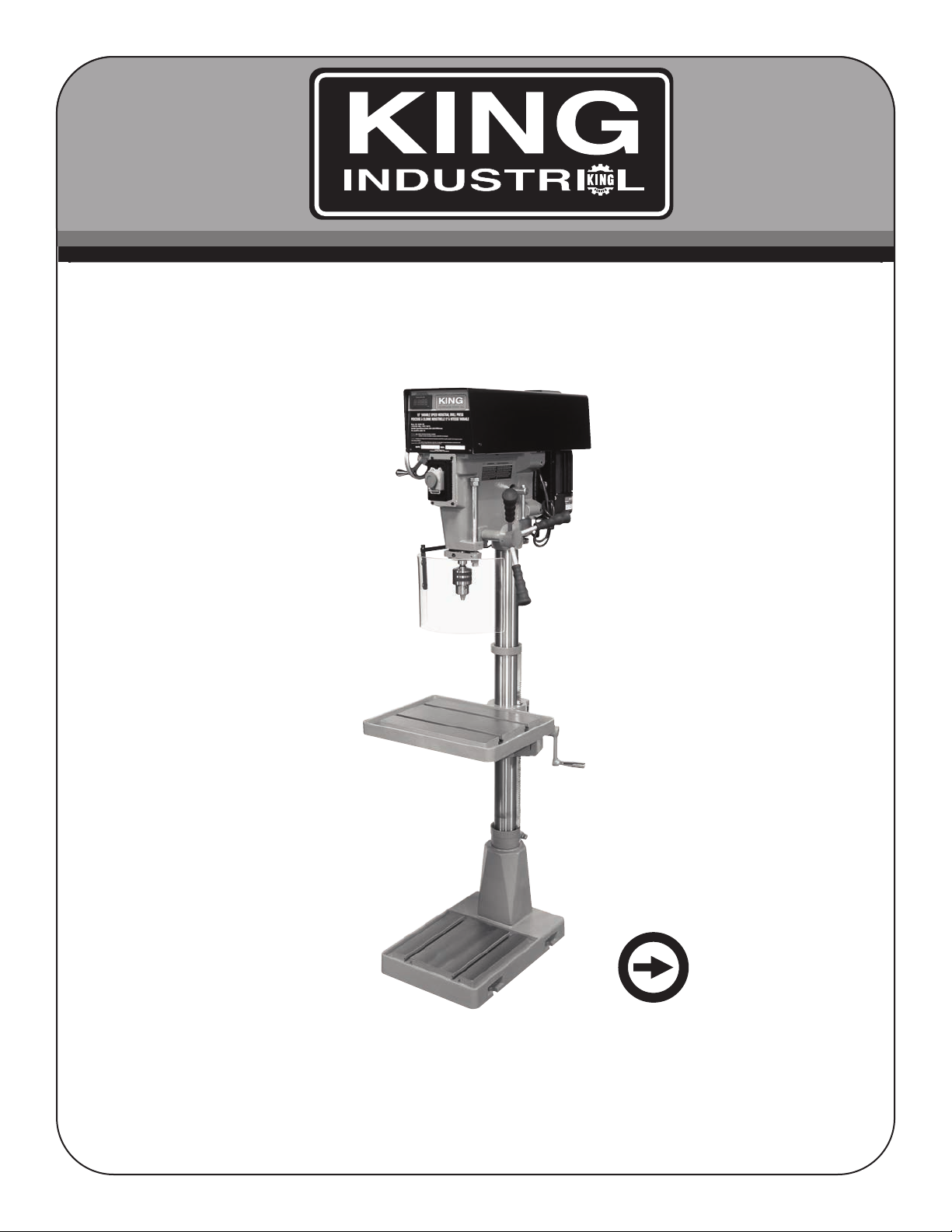
15” VARIABLE SPEED
INDUSTRIAL DRILL PRESS
INSTRUCTION MANUAL
COPYRIGHT © 2017 ALL RIGHTS RESERVED BY KING CANADA TOOLS INC.
MODEL: KC-30HS-VS
Page 2

WARRANTY INFORMATION
2-YEAR
LIMITED WARRANTY
FOR THIS 15” DRILL PRESS
OFFERS A 2-YEAR LIMITED WARRANTY
KING CANADA TOOLS
FOR NON-COMMERCIAL USE.
PROOF OF PURCHASE
Please keep your dated proof of purchase for warranty and servicing purposes.
REPLACEMENT PARTS
Replacement parts for this product are available at our authorized King Canada service centers across Canada.
LIMITED TOOL WARRANTY
King Canada makes every effort to ensure that this product meets high quality and durability standards. King Canada warrants to the
original retail consumer a 2-year limited warranty as of the date the product was purchased at retail and that each product is free from
defects in materials. Warranty does not apply to defects due directly or indirectly to misuse, abuse, normal wear and tear, negligence or
accidents, repairs done by an unauthorized service center, alterations and lack of maintenance. King Canada shall in no event be liable
for death, injuries to persons or property or for incidental, special or consequential damages arising from the use of our products.
To take advantage of this limited warranty, return the product at your expense together with your dated proof of purshase to an authorized
King Canada service center. Contact your retailer or visit our web site at www.kingcanada.com for an updated listing of our authorized
service centers. In cooperation with our authorized serviced center, King Canada will either repair or replace the product if any part or
parts covered under this warranty which examination proves to be defective in workmanship or material during the warranty period.
NOTE TO USER
This instruction manual is meant to serve as a guide only. Specifications and references are subject to change without prior notice.
PARTS DIAGRAM & PARTS LISTS
Refer to the Parts section of the King Canada web site for the most updated parts diagram and parts list.
KING CANADA INC. DORVAL, QUÉBEC, CANADA H9P 2Y4
www.kingcanada.com
Page 3

GENERAL SAFETY INSTRUCTIONS
FOR POWER TOOLS
1. KNOW YOUR TOOL
Read and understand the owners manual and labels affixed to the
tool. Learn its application and limitations as well as its specific
potential hazards.
2. GROUND THE TOOL.
This tool is equipped with an approved 3-conductor cord and a
3-prong grounding type plug to fit the proper grounding type
receptacle. The green conductor in the cord is the grounding wire.
NEVER connect the green wire to a live terminal.
3. KEEP GUARDS IN PLACE.
Keep in good working order, properly adjusted and aligned.
4. REMOVE ADJUSTING KEYS AND WRENCHES.
Form habit of checking to see that keys and adjusting wrenches
are removed from tool before turning it on.
5. KEEP WORK AREA CLEAN.
Cluttered areas and benches invite accidents. Make sure the floor
is clean and not slippery due to wax and sawdust build-up.
6. AVOID DANGEROUS ENVIRONMENT.
Don’t use power tools in damp or wet locations or expose them to
rain. Keep work area well lit and provide adequate surrounding
work space.
7. KEEP CHILDREN AWAY.
All visitors should be kept a safe distance from work area.
8. MAKE WORKSHOP CHILD-PROOF.
-with padlocks, master switches or by removing starter keys.
9. USE PROPER SPEED.
A tool will do a better and safer job when operated at the proper
speed.
10. USE RIGHT TOOL.
Don’t force the tool or the attachment to do a job for which it was
not designed.
11. WEAR PROPER APPAREL.
Do not wear loose clothing, gloves, neckties or jewelry (rings,
watch) because they could get caught in moving parts. Non-slip
footwear is recommended. Wear protective hair covering to
contain long hair. Roll up long sleeves above the elbows.
12. ALWAYS WEAR SAFETY GLASSES.
Always wear safety glasses (ANSI Z87.1). Everyday eye-glasses
only have impact resistant lenses, thet are NOT safety glasses.
Also use a face or dust mask if cutting operation is dusty.
13. DON’T OVERREACH.
Keep proper footing and balance at all times.
14. MAINTAIN TOOL WITH CARE.
Keep tools sharp and clean for best and safest performance. Follow
instructions for lubricating and changing accessories.
15. DISCONNECT TOOLS.
Before servicing, when changing accessories or attachments.
16. AVOID ACCIDENTAL STARTING.
Make sure the swich is in the ‘’OFF’’ position before plugging in.
17. USE RECOMMENDED ACCESSORIES.
Consult the manual for recommended accessories. Follow the
instructions that accompany the accessories. The use of improper
accessories may cause hazards.
18. NEVER STAND ON TOOL.
Serious injury could occur if the tool tips over. Do not store
materials such that it is necessary to stand on the tool to reach
them.
19. CHECK DAMAGED PARTS.
Before further use of the tool, a guard or other parts that are
damaged should be carefully checked to ensure that they will
operate properly and perform their intended function. Check for
alignment of moving parts, breakage of parts, mounting, and any
other conditions that may affect its operation. A guard or other parts
that are da -maged should be properly repaired or replaced.
20. NEVER LEAVE MACHINE RUNNING
UNATTENDED.
Turn power ‘’OFF’’. Don’t leave any tool running until it comes to a
complete stop.
SPECIFIC SAFETY INSTRUCTIONS FOR 15” DRILL PRESS
1. USING A DRILL PRESS VISE. When using a drill press vise, always
fasten it to the table.
2. NEVER DO “FREEHAND WORK”. Never do any work “Freehand”
(hand holding the workpiece rather than supporting it on the table)
except when you have polishing to do.
3. NEVER move the head or table while the drill press is running.
4. USE THE RECOMMENDED SPINDLE SPEED for the specific
operation and workpiece material.
5. NEVER climb on the drill press table, it could break or pull the entire
drill press down on you.
6. KEEP HANDS well away from the drill bit and all movingparts. Use
a hold-down or clamp to secure the workpiece, and use a brush, not
hands, to clear away chips and dust.
7. BE SURE THAT THE DRILL BIT IS SECURELY INSTALLED in the
chuck before operation.
8. BE SURE THE DRILL BIT has gained full operating speed before
beginning to drill.
9. ALWAYS USE a clean, properly sharpened bit. Dirty or dull bits are
unsafe and can lead to accidents.
10. USE SUITABLE WORKPIECE SUPPORT if the workpiece does
not have a flat surface.
11. DO NOT PUSH OR FORCE THE BIT into the workpiece. The drill
will perform better and more safely when working at the rate feed
for which it was designed.
12. AVOID WORKING FROM AWKWARD OR OFF BALANCE
POSITIONS. Do not overreach and keep both feet on floor.
13. KEEP GUARDS IN PLACE and in working order. If a guard must
be removed for maintenance or cleaning be sure it is properly
reinstalled before using the machine again.
14. NEVER LEAVE THE MACHINE unattended while it is running or
with the power on.
Page 4

ELECTRICAL INFORMATION
WARNING
ALL ELECTRICAL CONNECTIONS MUST BE DONE BY A QUALIFIED ELECTRICIAN. FAILURE TO COMPLY MAY RESULT IN SERIOUS
INJURY! ALL ADJUSTMENTS OR REPAIRS MUST BE DONE WITH THE MACHINE DISCONNECTED FROM THE POWER SOURCE.
FAILURE TO COMPLY MAY RESULT IN SERIOUS INJURY!
POWER SUPPLY
WARNING: YOUR DRILL PRESS MUST BE CONNECTED TO A 115V
WALL OUTLET, WITH A MINIMUM 15-AMP. BRANCH CIRCUIT AND USE
A 15-AMP TIME DELAY FUSE OR CIRCUIT BREAKER. FAILURE TO
CONNECT IN THIS WAY CAN RESULT IN INJURY FROM SHOCK OR
FIRE.
GROUNDING
Your drill press must be properly grounded. Not all outlets are properly
grounded. If you are not sure if your outlet is properly grounded, have it
checked by a qualified electrician.
WARNING: IF NOT PROPERLY GROUNDED, THIS DRILL PRESS CAN
CAUSE ELECTRICAL SHOCK, PARTICULARLY WHEN USED IN DAMP
LOCATIONS. TO AVOID SHOCK OR FIRE, IF THE POWER CORD IS
WORN OR DAMAGED IN ANY WAY, HAVE IT REPLACED IMMEDIATELY.
If this drill press should malfunction or breakdown, grounding provides a
path of least resistance for electric current, to reduce the risk of electric
shock. This drill press is equipped with a cord having an
equipment-grounding conductor and grounding plug. The plug must be
plugged into an appropriate outlet that is properly installed and grounded in
accordance with all local codes and ordinances.
WARNING: TO MAINTAIN PROPER GROUNDING, DO NOT REMOVE OR
ALTER THE GROUNDING PRONG IN ANY MANNER.
115V OPERATION
As received from the factory, your drill press is ready to run for 115V
operation. This machine is intended for use on a circuit that has an outlet
and a plug which looks like the one illustrated in Fig.1.
WARNING: DO NOT USE A TWO-PRONG ADAPTER(S) FOR THEY ARE
NOT IN ACCORDANCE WITH LOCAL CODES AND ORDINANCES.
NEVER USE IN CANADA.
EXTENSION CORDS
The use of any extension cord will cause some loss of power. If you do not
have a choice, use the table in Fig.2 to determine the minimum
wire size (A.W.G-American Wire Gauge) extension cord
needed. Use only 3-wire extension cords which have 3-prong
grounding type plugs and 3-hole receptacles which accept the
tool’s plug.
TURNING THE DRILLPRESS ON/OFF
This Drill Press comes with a 2 step activation safety switch, refer
to Fig.3, which starts and stops the machine. To turn the Drill Press
on:
1. Push up on the emergency stop button (A) Fig.3 and lift the switch
cover (B) upwards as shown.
2. Press the green On button (C) to start the Drill Press.
3. To stop the Drill Press, you can either press the red Off button (D)
or lower the switch cover and push the large emergency stop
button (E).
PROPERLY GROUNDED OUTLET
CURRENT CARRYING
PRONGS
GROUNDING
PRONG
Figure 1
Tool’s
Amperage
Rating
3-6
6-8
8-10
10-12
12-16
Cord Size in A.W.G.
Cord Length in Feet
25 50 100 150
18 16 16 14
18 16 14 12
18 16 14 12
18 16 14 12
14 12 - -
Figure 2
For circuits that are further away from the electrical circuit box,
the wire size must be increased proportionately in order to
deliver ample voltage to the drill press motor. Refer to Fig.2
for wire length and size.
Figure 3
Page 5

GETTING TO KNOW YOUR DRILL PRESS
1. Variable speed digital readout.
2. Speed adjusting handwheel.
3. 2 step activation safety switch.
4. Safety guard.
5. 5/8” chuck.
6. Table.
7. Base.
8. Head locking handle.
9. Depth stop rod.
10. Feed handle (1 of 3).
11. Column and rack.
12. Table raising/lowering handle.
13. Safety guard lock knob.
14. Limit switch.
15. Safety guard height adjusting lock
knob.
16. Spring return.
SPECIFICATIONS
FIGURE 4
MODEL KC-30HS-VS
Capacity 5/8”
Chuck size 5/8”
Swing 15”
Max. distance chuck to column 7-1/2”
Max. distance chuck to table 27-1/2”
Stroke 6”
Table size 18” x 14”
Spindle taper JT#3
Variable speeds 400 - 5,000 RPM
Table T-slots 9/16”
Quill diameter 2-1/4”
Column diameter 3”
Motor/Voltage 14 Amp. @ 115V, 7 Amp. @ 230V
Pre-wired 115V
Ass. dimensions (LxWxH)/weight
Pkg dimensions (LxWxH)/weight
18” x 28” x 71-1/2” / 310 lbs
22” x 32” x 70” / 375 lbs
FIGURE 5
Page 6

ASSEMBLY
ASSEMBLY
This drill press comes partially assembled and requires minimal assembly
and set up before being put into use.
INSTALLING TABLE HEIGHT ADJUSTMENT HANDLE
1. Align the set screw (A) Fig.6 in the table height adjustment handle (B)
with the flat portion of the handle shaft.
2. Slide the table height adjustment handle (B) onto the shaft and
tighten the set screw (A) using a 4mm hex. key.
RAISING THE HEAD
This drill press is shipped with the head lowered. To operate this drill
press correctly, the head must be raised.
1. Loosen the head locking handle (A) Fig.7 and place a block of wood
(B) on the table and under the bottom of the head as shown.
2. Loosen table lock handle (C), then turn table height adjustment handle
(D) to raise the head.
3. Once the head is positioned at a comfortable height, retighten head
locking handle (A) and table lock handle (C).
4. Loosen and move up the column collar (E) until it comes in contact
with the bottom of the head, secure the column collar up against the
head by tightening the large hex. bolt and hex. nut.
INSTALLING THE 5/8” CHUCK
FIGURE 6
FIGURE 7
1. Slide the 5/8” chuck (A) Fig.8 onto the tapered end of the spindle (B).
2. Place a piece of wood on the table and using the down-feed handles,
lower the quill assembly against the piece of wood on the table to
secure the chuck on the spindle.
FIGURE 8
Page 7

ADJUSTMENTS AND OPERATION
RAISING OR LOWERING WORK TABLE
1. Loosen table lock handle (A) Fig.9.
2. Turn the table height adjustment handle (B) until the table is at the
desired height.
3. Retighten table lock handle (A).
ADJUSTING ANGLE OF WORK TABLE
1. Loosen table lock handle (A) Fig.9.
2. Swing the table (C) to the desired position.
3. Retighten table lock handle (A).
Note: When working with taller workpieces, swing the table 180° out of
the way and use the base as a table.
USING THE DEPTH STOP
The depth stop mechanism Fig.10 allows repetitive drilling to an equal
depth, to adjust the depth stop mechanism:
FIGURE 9
1. Lower the downfeed handles until your cutting tool reaches the desired
drilling depth.
2. At the same time, position the bottom hex. nut (A) Fig.10 against the
head casting (B).
3. Release the downfeed handles and check your adjustment.
4. If properly set, tighten hex. nut (C) against hex. nut (A) to secure the
adjustment. Depth stop mechanism is now set and you can now do
repetitive drilling at equal depth.
CHANGING SPEED
This drill press has a variable spindle speed range of 400 to 5000 RPM,
the speed setting is conveniently displayed on the digital readout on the
head of the drill press. To set the spindle speed:
WARNING! Always adjust the spindle speed while the drill press is
running to avoid damaging the speed adjustment mechanism.
1. Turn the drill press on.
2. The spindle speed is controled by the speed adjusting handwheel (A)
Fig.11 located on the left side of the drill press head.
3. Turn the handwheel clockwise to increase the spindle speed.
4. Turn the handwheel counterclockwise to decrease the spindle speed.
5. Refer to the digital readout (B) on the front of the drill press head to
set the desired speed.
FIGURE 10
Refer to the reference chart (Fig.12) for recommended speed selection,
based on the drill bit size and workpiece material.
FIGURE 11
Page 8

ADJUSTMENTS & OPERATION
REFERENCE CHART FOR SPINDLE SPEED SELECTION - BASED ON BIT SIZE/WORKPIECE MATERIAL
WORKPIECE MATERIAL
BIT SIZE (DIAMETER)
1-16” (2 mm)
1/8" (3 mm)
3/16" (5 mm)
1/4" (6 mm)
5/16" (8 mm)
3/8" (10 mm)
7/16" (11 mm)
1/2" (13 mm)
The information in the above chart is supplied as a general guide only. For best results always follow the speed recommendations supplied
with the drill bits being used.
INSTALLING A DRILL BIT IN THE 5/8” CHUCK
1. Swing the chuck safety guard out of the way.
2. Insert the chuck key (A) Fig.13 into the chuck (B) as shown, turn chuck
key counterclockwise to open the chuck jaws.
CAST STEEL
1900 - 2445
1220 - 1275
765 - 815
610
480-490
380-405
350
300-305
TOOL STEEL
REVOLUTIONS PER MINUTE (RPM)
2865-3665
1835-1910
1145-1220
915-955
715-735
570-610
520-525
440-460
FIGURE 12
CAST IRON
3820-4890
2445-2545
1530-1630
1220-1275
955-980
765-815
700
560-610
MILD STEEL
4775-6110
3055-3185
1910-2035
1530-1590
1195-1220
955-1020
870
735-765
ALUM. & COPPER
9550-12225
6110-6365
3820-4075
3055-3180
2390-2445
1910-2035
1740-1745
1470-1530
3. Insert a drill bit (C).
4. Tighten the chuck key to secure the drill bit in the chuck.
USING AND AJUSTING THE LIMIT SWITCH PROTECTED
SAFETY GUARD
The limit switch safety guard (A) Fig.14 is intended to protect the operator
during drilling operations. If the safety guard is not positioned in its closed
position (in front of the drill chuck as shown), the safety guard limit switch
will prevent the drill press from starting. Close the safety guard and then
press the green On button to start. If the safety guard is opened during a
drilling operation the drill press will shut off automatically, the safety guard
will need to be closed and the green On button will need to be pressed
to restart drill press.
To adjust the safety guard:
1. The height of the safety guard (A) Fig.14 needs to be adjusted so it
covers the cutting tool. To adjust the height of the safety guard
assembly loosen lock handle (D), move the safety guard bar (B) up or
down until the safety guard is positioned correctly. Retighten lock
handle (D).
2. To lock and prevent the bar (B) and safety guard (A) from opening
during an operation, tighten lock knob (C).
FIGURE 13
3. Always make sure the hex. nut (E) is tight, to prevent the safety guard
from pivoting at this point. The bar (B) and safety guard (A) must move
together.
It is recommended to test the limit switch safety guard before any drilling
operation. Turn drill press on and open the safety guard, the drill press
MUST shut off. If it doesn’t, the safety guard limit switch needs to be
replaced or reinstalled correctly.
FIGURE 14
Page 9

MAINTENANCE
MAINTENANCE
WARNING! For your own safety, turn the switch “OFF” and remove the
plug from the power source before maintaining or lubricating your drill
press.
• Keep the Drill Press clean and free of dust and debris. Painted surfaces
can be wiped with a damp rag.
• Periodically lubricate all sliding or moving parts including the column (A)
Fig.15, rack (B) and the quill (C) (use any all purpose grease, available
at any hardware store).
• Bearings in the quill and the V-belt pulleys are sealed and permanently
lubricated – no further lubrication is required.
• Frequently blow out any dust that may accumulate inside the motor. After operation, remove chips or dirt on the machine and apply a coat of
furniture-type paste wax to the table and the column, this will help keep the surfaces clean and free of rust.
FIGURE 15
PROBLEM
Drill bit burns.
Wood splinters on underside of workpiece.
Workpiece torn loose
from hand.
Drill bit binds in
workpiece.
Excessive drill bit
wobbling.
Quill returns too fast or
too slow.
Chuck will not stay attached to the spindle. It
falls off when trying to
install it.
PROBABLE CAUSE
1. Incorrect speed.
2. Chips not comming out of hole.
3. Dull drill bit.
4. Feeding too slow.
5. Not lubricated.
1. No “Back-up material” under the
workpiece.
1. Not supported or clamped properly.
1. Workpiece is pinching the drill bit or there
is an excessive feeding pressure.
1. Bent drill bit.
2. Worn spindle bearings.
3. Drill bit is not properly installed in the
chuck.
4. Chuck not properly installed.
1. Spring has improper tension.
1. Dirt, grease or oil on the tapered inside
surface of the chuck or on the spindle
tapered surface.
SOLUTION
1. Change the speed.
2. Retract the drill bit frequently to clear the chips.
3. Resharpen the drill bit.
4. Feeding too fast...allow the drill bit to cut.
5. Lubricate the drill bit with cutting or motor oil.
1. Support the workpiece or clamp it.
1. Support the workpiece or clamp it.
1. Support the workpiece or clamp it. Reduce feeding
pressure.
1. Use a straight drill bit.
2. Replace the bearings.
3. Install drill bit properly.
4. Install chuck properly.
1. Adjust the spring tension.
1. Using a household detergent, clean the tapered surfaces
of the chuck and the spindle to remove the dirt, grease
and oil.
 Loading...