


10” CABINET TABLE SAWS
WITH RIVING KNIFE
09/2013
MODEL:
KC-10JCS/J52 (52” Max Rip)
OPTIONAL
KC-10JCS/J52 shown here with optional 33 1/4” laminated melamine extension table and 2 sturdy adjustable supporting legs (mod. EXT-5052)
Left Tilt
MODEL:
KC-10JCS/J30 (30” Max Rip)
INSTRUCTION MANUAL
COPYRIGHT © 2010 ALL RIGHTS RESERVED BY KING CANADA TOOLS INC.

WARRANTY INFORMATION
|
|
|
|
|
|
|
|
|
|
|
|
|
|
|
|
|
|
|
|
|
|
|
|
|
|
|
|
|
|
|
|
|
|
|
|
|
|
|
|
|
|
|
|
|
|
|
|
|
|
|
|
|
|
|
|
|
|
|
|
|
|
|
|
|
|
|
|
|
|
|
|
|
|
|
|
|
|
|
|
|
|
|
|
|
|
|
|
|
|
|
|
|
|
|
|
|
|
|
|
|
|
|
|
|
|
|
|
|
|
|
|
|
|
|
|
|
|
|
|
|
|
|
|
|
|
|
|
|
|
|
|
|
|
|
|
|
|
|
|
|
|
|
|
|
|
|
2-YEAR |
KING CANADA TOOLS |
|
|
|
|
|
|
|
|
|
|
|
|
LIMITED WARRANTY |
OFFERS A 2-YEAR LIMITED WARRANTY |
|
|
|
|
|
|
|
|
|
|
FOR THIS 10” CABINET SAW |
FOR INDUSTRIAL USE. |
|
||||
|
|
|
|
|
|
|
|
|
|
|
|
|
|
|
PROOF OF PURCHASE
Please keep your dated proof of purchase for warranty and servicing purposes.
REPLACEMENT PARTS
Replacement parts for this product are available at our authorized King Canada service centers across Canada.
LIMITED TOOL WARRANTY
King Canada makes every effort to ensure that this product meets high quality and durability standards. King Canada warrants to the original retail consumer a 2-year limited warranty as of the date the product was purchased at retail and that each product is free from defects in materials. Warranty does not apply to defects due directly or indirectly to misuse, abuse, normal wear and tear, negligence or accidents, repairs done by an unauthorized service center, alterations and lack of maintenance. King Canada shall in no event be liable for death, injuries to persons or property or for incidental, special or consequential damages arising from the use of our products.
To take advantage of this limited warranty, return the product at your expense together with your dated proof of purshase to an authorized King Canada service center. Contact your retailer or visit our web site at www.kingcanada.com for an updated listing of our authorized service centers. In cooperation with our authorized serviced center, King Canada will either repair or replace the product if any part or parts covered under this warranty which examination proves to be defective in workmanship or material during the warranty period.
NOTE TO USER
This instruction manual is meant to serve as a guide only. Specifications and references are subject to change without prior notice.
PARTS DIAGRAM & PARTS LISTS
Refer to the Parts section of the King Canada web site for the most updated parts diagram and parts list.
KING CANADA INC. DORVAL, QUÉBEC, CANADA H9P 2Y4
www.kingcanada.com

GENERAL SAFETY INSTRUCTIONS |
FOR POWER TOOLS |
1. KNOW YOUR TOOL
Read and understand the owners manual and labels affixed to the tool. Learn its application and limitations as well as its specific potential hazards.
2. GROUND THE TOOL.
This tool is equipped with an approved 3-conductor cord and a 3-prong grounding type plug to fit the proper grounding type receptacle. The green conductor in the cord is the grounding wire. NEVER connect the green wire to a live terminal.
3. KEEP GUARDS IN PLACE.
Keep in good working order, properly adjusted and aligned.
4. REMOVE ADJUSTING KEYS AND WRENCHES.
Form habit of checking to see that keys and adjusting wrenches are removed from tool before turning it on.
5. KEEP WORK AREA CLEAN.
Cluttered areas and benches invite accidents. Make sure the floor is clean and not slippery due to wax and sawdust build-up.
6. AVOID DANGEROUS ENVIRONMENT.
Don’t use power tools in damp or wet locations or expose them to rain. Keep work area well lit and provide adequate surroun-ding work space.
7. KEEP CHILDREN AWAY.
All visitors should be kept a safe distance from work area.
8. MAKE WORKSHOP CHILD-PROOF.
-with padlocks, master switches or by removing starter keys.
9. USE PROPER SPEED.
A tool will do a better and safer job when operated at the proper speed.
10. USE RIGHT TOOL.
Don’t force the tool or the attachment to do a job for which it was not designed.
11. WEAR PROPER APPAREL.
Do not wear loose clothing, gloves, neckties or jewelry (rings,
watch) because they could get caught in moving parts. Non-slip footwear is recommended. Wear protective hair covering to contain long hair. Roll up long sleeves above the elbows.
12. ALWAYS WEAR SAFETY GLASSES.
Always wear safety glasses (ANSI Z87.1). Everyday eyeglasses only have impact resistant lenses, thet are NOT safety glasses. Also use a face or dust mask if cutting operation is dusty.
13. DON’T OVERREACH.
Keep proper footing and balance at all times.
14. MAINTAIN TOOL WITH CARE.
Keep tools sharp and clean for best and safest performance. Follow instructions for lubricating and changing accessories.
15. DISCONNECT TOOLS.
Before servicing, when changing accessories or attachments.
16. AVOID ACCIDENTAL STARTING.
Make sure the switch is in the ‘’OFF’’ position before plugging in.
17. USE RECOMMENDED ACCESSORIES.
Consult the manual for recommended accessories. Follow the instructions that accompany the accessories. The use of improper accessories may cause hazards.
18. NEVER STAND ON TOOL.
Serious injury could occur if the tool tips over. Do not store materials such that it is necessary to stand on the tool to reach them.
19. CHECK DAMAGED PARTS.
Before further use of the tool, a guard or other parts that are damaged should be carefully checked to ensure that they will operate properly and perform their intended function. Check for alignment of moving parts, breakage of parts, mounting, and any other conditions that may affect its operation. A guard or other parts that are damaged should be properly repaired or replaced.
20. NEVER LEAVE MACHINE RUNNING UNATTENDED.
Turn power ‘’OFF’’. Don’t leave any tool running until it comes to a complete stop.
SPECIFIC SAFETY INSTRUCTIONS FOR TABLE SAWS
1. ALWAYS USE A GUARD.
Always use a guard, splitter and anti-kickback fingers on all “thrusawing” operations. Thru-sawing operations are those when the blade cuts completely through the workpiece as in ripping or crosscutting.
2. ALWAYS HOLD THE WORK.
Always hold the work firmly against the miter gauge or fence.
3. ALWAYS USE A PUSH STICK.
For ripping narrow stock. Refer to ripping applications in instruction manual where push sticks are covered in detail.
4. NEVER.
Never perform any operations “free-hand” which means using your hands to support or guide the workpiece. Always use either the fence or the miter gauge to position and guide the workpiece.
5. NEVER.
Never stand or have any part of your body in line with the path of the saw blade.
6. NEVER REACH BEHIND.
Never reach behind or over the cutting tool with either hand for any reason.
7. MOVE THE RIP FENCE.
Move the rip fence out of the way when crosscutting.
8. WHEN CUTTING MOULDINGS.
Never run the stock between the fence and the moulding cutter-
head. Refer to moulding applications in the accessory manual for details.
9. DIRECTION OF FEED.
Feed work into the blade against the direction of rotation.
10. NEVER.
Never use the fence as a cut-off gauge when you are crosscutting.
11. NEVER.
Never attempt to free a stalled saw blade without first turning the saw OFF.
12. PROVIDE ADEQUATE SUPPORT.
To the rear and sides of the table saw for wide or long workpieces.
13. AVOID KICKBACKS.
Avoid kickbacks (work thrown back towards you) by keeping the blade sharp, by keeping the rip fence parallel to the saw blade, by keeping the splitter and anti-kickback fingers and guard in place and operating, by not releasing work before it is pushed all the way past the saw blade, and by not ripping work that is twisted or warped or does not have a straight edge to guide along the fence.
14. AVOID AWKWARD OPERATIONS.
Avoid awkward operations and hand positions where a sudden slip could cause your hand to move into the spinning blade.

GETTING TO KNOW YOUR 10” TABLE SAW
AND SPECIFICATIONS
Model KC-10JCS/J52 shown here with optional melamine extension table mod. EXT-5052
1. |
4” Dust chute |
11. Support legs/adjustable feet (Optional accessory EXT-5052) |
|
2. |
Emergency stop |
12. |
Motor access door |
3. |
Switch with reset button |
13. |
Blade raising handwheel |
4. |
Table insert |
14. |
Handwheel lock knob |
5. |
2pc. blade guard with riving knife |
15. Angle pointer and scale |
|
6. |
Miter gauge |
16. |
Blade tilting handwheel |
7. |
T-square rip fence |
17. |
Handwheel lock knob |
8. |
Laminated table (Optional accessory EXT-5052) |
18. |
Dado table insert |
9. |
Front rail |
19. |
Riving knife |
10. Slide tube |
20. |
Rear rail |
|
SPECIFICATIONS CHART
MODEL |
KC-10JCS/J30 |
KC-10JCS/J52 |
|||
Blade diameter |
10” |
10” |
|||
Blade tilts |
Left |
Left |
|||
Depth of cut at 45° |
2 |
3/16” |
2 |
3/16” |
|
Depth of cut at 90° |
3 |
1/8” |
3 |
1/8” |
|
Table size with extensions |
40” x 27” |
40” x 27” |
|||
Diameter of arbor |
5/8” |
5/8” |
|||
Dado width capacity |
13/16” |
13/16” |
|||
Dado maximum blade diameter |
8” |
8” |
|||
Motor |
2 |
HP, 3,450 RPM |
2 |
HP, 3,450 RPM |
|
Voltage (pre-wired: 220V) |
120V/240V, 1 phase, 60 Hz |
120V/240V, 1 phase, 60 Hz |
|||
ELECTRICAL REQUIREMENTS & |
SWITCH OPERATION |
WARNING!
ALL ELECTRICAL CONNECTIONS MUST BE DONE BY A QUALIFIED ELECTRICIAN. FAILURE TO COMPLY MAY RESULT IN SERIOUS INJURY! ALL ADJUSTMENTS OR REPAIRS MUST BE DONE WITH THE MACHINE DISCONNECTED FROM THE POWER SOURCE. FAILURE TO COMPLY MAY RESULT IN SERIOUS INJURY!
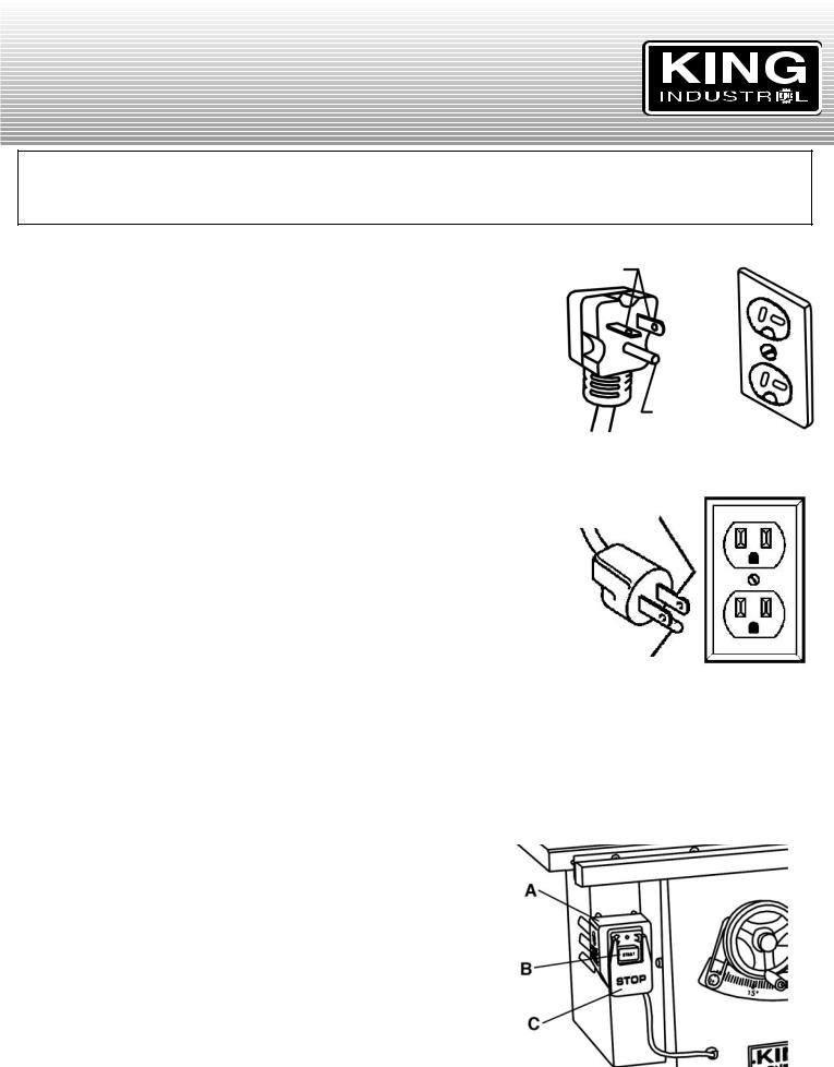
POWER SUPPLY (240V)
WARNING: THIS CABINET SAW CAME PRE-WIRED FOR 240V OPERATION AND MUST BE CONNECTED TO AN APPROPRIATELY GROUNDED 240V OUTLET AS SHOWN IN FIG.1.
GROUNDING
WARNING: IF OUTLET IS NOT PROPERLY GROUNDED, THIS CABINET SAW CAN CAUSE ELECTRICAL SHOCK, PARTICULARLY WHEN USED IN DAMP LOCATIONS. TO AVOID SHOCK OR FIRE, IF THE POWER CORD IS WORN OR DAMAGED IN ANY WAY, HAVE IT REPLACED IMMEDIATELY.
Not all outlets are properly grounded. If you are not sure if your outlet is properly grounded, have it checked by a qualified electrician.
This cabinet saw must be grounded, if it should malfunction or breakdown, grounding provides a path of least resistance for electric current, which reduces the risk of electric shock.
WARNING: TO MAINTAIN PROPER GROUNDING OF YOUR TABLE SAW, DO NOT REMOVE OR ALTER THE GROUNDING PRONG IN ANY MANNER.
POWER SUPPLY (120V)
WARNING! This table saw must be connected to a 30 amp. circuit if 120V, single phase operation is desired. It is recommended to contact your authorized service center or qualified electrician to install the plug, change reset and change the connections from 240V to 120V.
1.Disconnect the machine from its power source.
2.The table saw comes with four motor leads that are connected for 240V operation. Reconnect these four motor leads for 240V operation, as indicated on the inside of the motor and/or capacitor cover.
3.The 240V plug supplied with the table saw must be replaced with a CSA listed plug suitable for 120V operation. This plug is illustrated in Fig.2. The 10A reset must also be changed to a 20Amp reset. Contact your authorized service center or qualified electrician to install the plug, change reset and change the connections from 240V to 120V. The table saw must comply with all local and national codes after the 120V plug is installed.
4.A table saw with a 120V plug should only be connected to an outlet having the same configuration as illustrated by the grounded outlet box in Fig.2. No adaptor is available or should be used for 120V operation.
EXTENSION CORDS
The use of any extension cord will cause some loss of power. Use the following table to determine the minimum wire size (A.W.G-American Wire Gauge) extension cord you will need. Use only 3-wire extension cords which have 3-prong grounding type plugs and 3-hole receptacles which accept the tool’s plug. For circuits that are further away from the electrical circuit box, the wire size must be increased proportionately in order to deliver ample voltage to the cabinet saw motor. Refer to Fig.3 for wire length and size.
SWITCH OPERATION
The switch (A) Fig.4 needs to be installed to underside of the front rail, see assembly section in this manual for further instructions. Do not turn the cabinet saw on until all assembly and adjustment instructions have been done.
To start the cabinet saw, press the green start button (B) Fig.4 and to stop the cabinet saw, press the red emergency stop button (C).
This switch is equipped with a thermal overload protector, if motor is overloaded during use, the reset will trip and stop the motor. Wait a few minutes to allow motor to cool down, press the reset button (on right side of switch) and turn cabinet saw on to continue.
PROPERLY
GROUNDED OUTLET
CURRENT CARRYING PRONGS
GROUNDING
PRONG
FIGURE 1
PROPERLY
GROUNDED OUTLET
CURRENT CARRYING
PRONGS
GROUNDING PRONG
FIGURE 2
LENGTH OF |
WIRE SIZES REQUIRED |
EXTENSION CORD |
(AMERICAN WIRE GAUGE) |
|
240V LINES ONLY |
0-25 FEET |
NO.12 |
26-50 FEET |
NO.12 |
51-100 FEET |
NO.10 |
|
|
FIGURE 3
FIGURE 4
 Loading...