

Page 1

7” INDUSTRIAL PLANER/MOULDER
04/2017
MODEL: KC-240M
INSTRUCTION MANUAL
COPYRIGHT © 2016 ALL RIGHTS RESERVED BY KING CANADA TOOLS INC.
Page 2

WARRANTY INFORMATION
2-YEAR
LIMITED WARRANTY
FOR THIS 7” PLNER/MOULDER
OFFERS A 2-YEAR LIMITED WARRANTY
KING CANADA TOOLS
FOR COMMERCIAL USE.
PROOF OF PURCHASE
Please keep your dated proof of purchase for warranty and servicing purposes.
REPLACEMENT PARTS
Replacement parts for this product are available at our authorized King Canada service centres across Canada.
LIMITED TOOL WARRANTY
King Canada makes every effort to ensure that this product meets high quality and durability standards. King Canada warrants to the
original retail consumer a 2-year limited warranty as of the date the product was purchased at retail and that each product is free from
defects in materials. Warranty does not apply to defects due directly or indirectly to misuse, abuse, normal wear and tear, negligence or
accidents, repairs done by an unauthorized service centre, alterations and lack of maintenance. King Canada shall in no event be liable
for death, injuries to persons or property or for incidental, special or consequential damages arising from the use of our products.
To take advantage of this limited warranty, return the product at your expense together with your dated proof of purshase to an authorized
King Canada service centre. Contact your retailer or visit our web site at www.kingcanada.com for an updated listing of our authorized
service centres. In cooperation with our authorized serviced centre, King Canada will either repair or replace the product if any part or
parts covered under this warranty which examination proves to be defective in workmanship or material during the warranty period.
NOTE TO USER
This instruction manual is meant to serve as a guide only. Specifications and references are subject to change without prior notice.
PARTS DIAGRAM & PARTS LISTS
Refer to the Parts section of the King Canada web site for the most updated parts diagram and parts list.
KING CANADA INC. DORVAL, QUÉBEC, CANADA H9P 2Y4
www.kingcanada.com
Page 3

GENERAL
SAFETY INSTRUCTIONS
VOLTAGEWARNING: Before connecting the machine to a power source (receptacle, outlet, etc.) be sure the voltage supplied is the same as
that specified on the nameplate. A power source with voltage greater than specified can result in SERIOUSINJURY to the user - as well as damage
the machine. If in doubt DONOTPLUGINTHETOOL. Using a power source with voltage less than the nameplate is harmful to the motor.
1. KNOW YOUR MACHINE
Read and understand the owners manual and labels affixed to
the machine. Learn its application and limitations as well as its
specific potential hazards.
2. GROUND THE MACHINE.
This machine is equipped with an approved 3-conductor cord and
a 3-prong grounding type plug to fit the proper grounding type
receptacle. The green conductor in the cord is the grounding wire.
NEVER connect the green wire to a live terminal.
3. KEEP GUARDS IN PLACE.
Keep in good working order, properly adjusted and aligned.
4. REMOVE ADJUSTING KEYS AND WRENCHES.
Form habit of checking to see that keys and adjusting wrenches
are removed from the machine before turning it on.
5. KEEP WORK AREA CLEAN.
Cluttered areas and benches invite accidents. Make sure the floor
is clean and not slippery due to wax and dust build-up.
6. AVOID DANGEROUS ENVIRONMENT.
Don’t use machinery in damp or wet locations or expose them to
rain. Keep work area well lit and provide adequate surrounding
work space.
7. KEEP CHILDREN AWAY.
All visitors should be kept a safe distance from work area.
8. MAKE WORKSHOP CHILD-PROOF.
Use padlocks, master switches or remove starter keys.
9. USE PROPER SPEED.
A machine will do a better and safer job when operated at the
proper speed.
10. USE RIGHT TOOL.
Don’t force the machine or the attachment to do a job for which it
was not designed.
11. WEAR PROPER APPAREL.
Do not wear loose clothing, gloves, neckties or jewelry (rings,
watch) because they could get caught in moving parts. Non-slip
footwear is recommended. Wear protective hair covering to
contain long hair. Roll up long sleeves above the elbows.
12. ALWAYS WEAR SAFETY GLASSES.
Always wear safety glasses (ANSI Z87.1). Everyday eyeglasses
only have impact resistant lenses, they are NOT safety glasses.
Also use a face or dust mask if cutting operation is dusty.
13. DON’T OVERREACH.
Keep proper footing and balance at all times.
14. MAINTAIN MACHINE WITH CARE.
Keep machine clean for best and safest performance. Follow
instructions for lubricating and changing accessories.
15. DISCONNECT MACHINE.
Before servicing, when changing accessories or attachments.
16. AVOID ACCIDENTAL STARTING.
Make sure the switch is in the ‘’OFF’’ position before plugging in.
17. USE RECOMMENDED ACCESSORIES.
Consult the manual for recommended accessories. Follow the
instructions that accompany the accessories. The use of improper accessories may cause hazards.
18. NEVER STAND ON TOOL.
Serious injury could occur if the machine tips over. Do not store
materials such that it is necessary to stand on the machine to
reach them.
19. CHECK DAMAGED PARTS.
Before further use of the machine, a guard or other parts that are
damaged should be carefully checked to ensure that they will
operate properly and perform their intended function. Check for
alignment of moving parts, breakage of parts, mounting, and any
other conditions that may affect its operation. A guard or other
parts that are damaged should be properly repaired or replaced.
20. NEVER LEAVE MACHINE RUNNING UNATTENDED.
Turn power ‘’OFF’’. Don’t leave any machine running until it comes
to a complete stop.
SPECIFIC SAFETY INSTRUCTIONS FOR PLANER/MOULDERS
1. Always wear eye protection when operating any machine.
2. Before starting up, recheck to make certain all holding screws are
tight.
3. Always stop motor and disconnect the power source before making
any kind of adjustment.
4. Be sure all guards are in place before operating equipment. Ensure
the chip deflectors are in place, with proper gaps between blades.
Ensure all covers are secured.
5. Read the instruction manual thoroughly and familiarize yourself with
the machine before attempting to operate.
6. Keep children away,all visitors should maintain a safe distance from
the machine.
7. After a long period of operation, stop the machine, disconnect the
power, and check the cutter head screws for tightness.
8. Don’t force-feed your work through the machine. Allow the feed
rollers to feed the workpiece through the machine automatically.
9. Check the feed roller bearings occasionally to be sure there are no
wood chips between the bearings and side plates. If bearings are
not seated firmly, the feed rollers will not hold stock firmly against
the table, and kickback could occur.
10. Use proper materials free from loose or tight knots, and avoid
materials that are warped or misshapen.
11. Never stand directly in line with either the infeed or outfeed sides
of the machine. Always stand to one side. With any power tool,
kickback is always a possibility.
12. Never remove more than 1/8” of material in a single pass through
the machine.
13. Never plane a board less than 8” in length.
14. Do not push or force stock into the cutterhead. The moulder will
perform better and safer when working at the rate for which it was
designed.
15. Always use clean, properly sharpened knives. Dirty or dull knives
are unsafe and can lead to accidents.
Page 4

ELECTRICAL INFORMATION
WARNING
ALL ELECTRICAL CONNECTIONS MUST BE DONE BY A QUALIFIED ELECTRICIAN. FAILURE TO COMPLY MAY RESULT IN SERIOUS
INJURY! ALL ADJUSTMENTS OR REPAIRS MUST BE DONE WITH THE MACHINE DISCONNECTED FROM THE POWER SOURCE.
FAILURE TO COMPLY MAY RESULT IN SERIOUS INJURY!
POWER SUPPLY
WARNING: YOUR PLANER/MOULDER MUST BE CONNECTED TO
A 220V, 15-AMP. MINIMUM BRANCH CIRCUIT. FAILURE TO
CONNECT IN THIS WAY CAN RESULT IN INJURY FROM SHOCK OR
FIRE.
GROUNDING
This Planer/Moulder must be grounded. If it should malfunction or
breakdown, grounding provides a path of least resistance for electric
current, to reduce the risk of electric shock. This Planer/Moulder is
equipped with a cord having an equipment-grounding conductor. The
plug must be plugged into an appropriate outlet that is properly installed
and grounded in accordance with all local codes and ordinances.
WARNING: TO MAINTAIN PROPER GROUNDING OF YOUR
PLANER/MOULDER, DO NOT REMOVE OR ALTER THE PLUG
GROUNDING PRONG IN ANY MANNER.
Not all outlets are properly grounded. If you are not sure if your outlet
is properly grounded, have it checked by a qualified electrician.
WARNING: IF NOT PROPERLY GROUNDED, THIS
PLANER/MOULDER CAN CAUSE ELECTRICAL SHOCK,
PARTICULARLY WHEN USED IN DAMP LOCATIONS. TO AVOID
SHOCK OR FIRE, IF THE POWER CORD IS WORN OR DAMAGED
IN ANY WAY, HAVE IT REPLACED IMMEDIATELY.
220V OPERATION
Your Planer/Moulder comes wired for 220V operation. The plug and the
required wall outlet are illustrated in Fig.1.
Starting and Stopping the automatic feed rollers
This machine is supplied with an independent motor which operates
the feed rollers. This motor is controlled by the On/Off switch (D) Fig.3,
it comes with a removable safety key (E). When the safety key is
removed from the switch and placed in a safe location, unauthorized
persons or children can’t turn the switch to the On position.
Reset Button (overload protector)
This machine comes with an overload reset button (F)Fig.3. If the
machine motor overheats, a safety mechanism stops the motor
automatically. To prevent motor over-heating, reduce load on motor or
check voltage. Allow motor to cool down, then press the reset button
and restart the machine. If the machine does not restart, wait an
additional 5 minutes before restarting.
PROPERLY GROUNDED
220V OUTLET
CURRENT CARRYING PRONGS
GROUNDING PRONG
FIGURE 1
EXTENSION CORDS
WARNING! IT IS NOT RECOMMENDED TO USE AN EXTENSION
CORD, BUT IF IT IS NECESSARY, READ THE FOLLOWING.
The use of any extension cord will cause some loss of power.
Depending on the length of extension cord needed, use the table (Fig.2)
to determine the minimum wire gauge (A.W.G-American Wire Gauge).
Use only 3-wire extension cords which have 3-prong grounding type
plugs and 3-hole receptacles which accept the tool’s plug.
For circuits that are further away from the electrical circuit box, the wire
thickness must be increased proportionately in order to deliver ample
voltage to the Planer/Moulder motor. The smaller the gauge of the
extension cord, the thicker it will be in diameter. Refer to Fig.2 for wire
length and size.
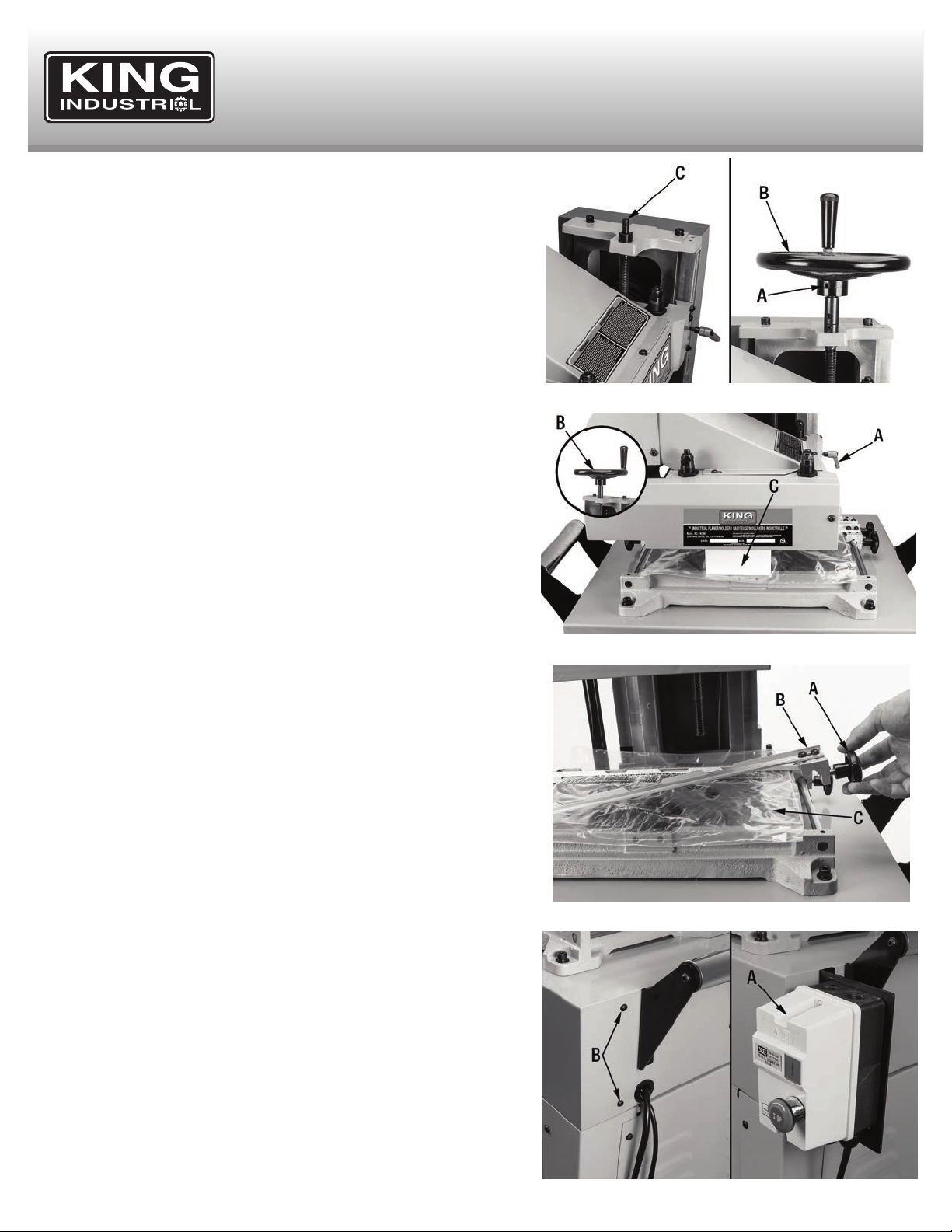
Starting and Stopping the Planer/Moulder Cutterhead
The magnetic switch (A) Fig.3 is located on the front right side of the
machine. To turn the machine “On” press the green button (B). To stop
the machine, push the red emergency stop button (C). Once you push
down on the emergency stop button (C), twist the button clockwise until
it pops up, only then will you be able to restart the machine.
LENGTH OF
EXTENSION CORD
0-25 FEET
26-50 FEET
51-100 FEET
WIRE GAUGE REQUIRED
(AMERICAN WIRE GAUGE)
220V LINES
NO.16
NO.14
NO.12
FIGURE 2
FIGURE 3
Page 5
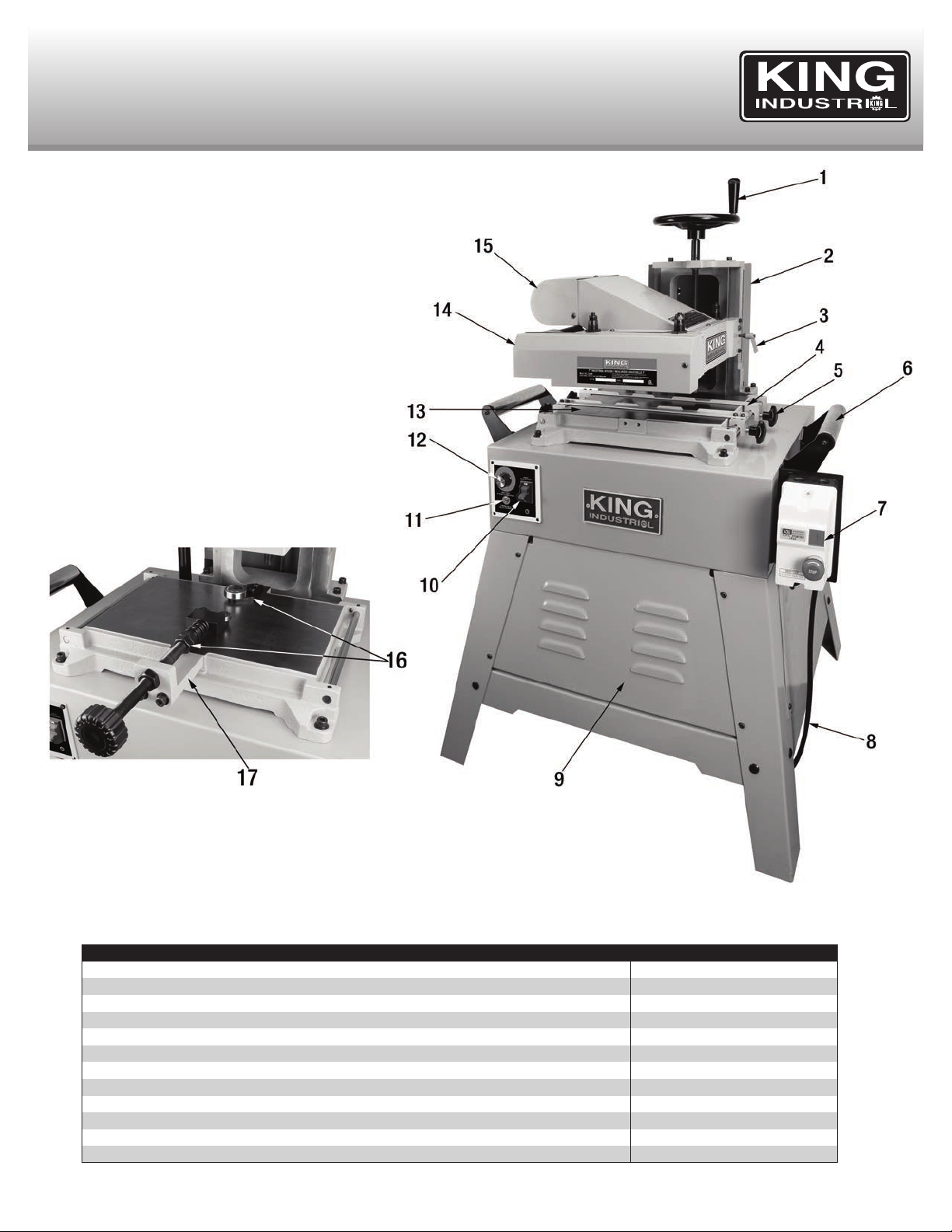
GETTING TO KNOW YOUR
7” PLANER/MOULDER
1. Cutterhead height adjustment handwheel
2. Drive belt safety guard
3. Cutterhead lock handle
4. Moulding guide fence (1 of 2)
5. Guide fence lock knob (1 of 4)
6. Table Extension Rollers
7. Cutterhead activating magnetic safety switch
8. Power cord
9. Front access panel
10. Feed motor switch with safety key
11. Thermal relay reset button
12. Variable feed rate control dial
13. Table
14. Feed motor
15. Dust Hood
16. Elliptical jig assembly
17. Elliptical jig mounting bracket
SPECIFICATIONS
MODEL KC-240M
Maximum planing width
Maximum moulding width 6-3/4”
Maximum thickness of stock 8”
Minimum thickness of stock 1/4”
Minimum length of stock 8”
Maximum depth of cut (planing/moulding) 1/8” / 3/4”
Cutterhead speed 7,000 RPM
Number of knives 2
Motor 2 HP, 12 Amp.
Voltage 220V, 1 phase, 60 Hz
Assembled dimensions (LxWxH)/weight 32” x 27-1/2” x 51” / 290 lbs
Package dimensions (LxWxH)/weight 36-1/4” x 30” x 49-1/4” / 355 lbs
7”
Page 6
ASSEMBLY & SETUP
INSTALLING THE CUTTERHEAD HEIGHT ADJUSTMENT HANDWHEEL
To install the cutterhead height adjustment handwheel:
1. Loosen the set screw (A) Fig.4 on the handwheel (B) using a 3mm hex. key so
that the handwheel can slide onto the shaft (C).
2. Attach the adjustment handwheel (B) to the shaft (C).
3. Retighten the set screw (A) to secure the handwheel.
REMOVING PROTECTIVE PLASTIC AND FOAM
This machine is shipped from the factory with the cutterhead resting on a
styrofoam block for support during transport. To remove the styrofoam block:
1. Loosen the cutterhead lock handle (A) Fig.5.
WARNING! Do not attempt to adjust the height of the cutterhead without first
loosening the cutterhead lock handle (A) Fig.5. Failure to do this could cause
premature wear of the locking mechanism.
FIGURE 4
2. After loosening the lock handle, rotate the cutterhead height adjustment
handwheel (B) counterclockwise to lift the cutterhead off of the styrofoam block
(C), remove styrofoam.
To remove the protective plastic sheet:
1. Loosen the fence lock knobs (A) Fig.6 and remove the two fences (B) from the
table.
2. Pull back the protective plastic (C) and discard it.
This machine is shipped from the factory with a protective coating on the table to
prevent rust during shipping and storage. This coating can be removed by wiping
the table with a rag soaked in kerosene, mineral spirits, or paint thinner. A plastic
scrapper can also be used to scrape off most of the coating, being careful not to
scratch the table.
MOUNTING THE MAGNETIC SAFETY SWITCH
The magnetic safety switch and mounting bracket (A) Fig.7 must be mounted to
the right side of the machine using two round head allen screws (B) which are
already mounted to the right side of the machine as shown.
FIGURE 5
FIGURE 6
FIGURE 7
Page 7

ASSEMBLY & SETUP
INSTALLING THE BELT ONTHE DRIVE PULLEYS
To install the belt on the drive drive pulleys:
1. Using the 6mm hex. key, remove the cap screw and washer (A) Fig.8 which is
used to secure the motor during transport. Once the screw has been removed,
the motor will swing freely.
2. Next, loosen and remove the 3 round head allen screws (A) Fig.9 using a 4mm
hex. key. Lift and remove the upper pulley cover (B).
3. Make sure the drive belt (C) is installed on the upper pulley (D) as shown.
FIGURE 8
4. Using the 4mm hex. key, loosen and remove the 4 round head allen screws
(A) Fig.10. Remove the rear access panel (B) from the stand in order to access
the motor.
5. Lift the motor (A) Fig.11 up and install the other end of the drive belt (B) in the
slot on the lower pulley (C).
6. Re-install the upper pulley cover and the rear access panel.
FIGURE 9
FIGURE 10
FIGURE 11
Page 8

ASSEMBLY & ADJUSTMENTS
INSTALLING LEVELING RUBBER FEET TO THE STAND
1. Install the 4 leveling rubber feet (A) Fig.12 to each stand leg (B) using a washer
(C) and two hex. nuts (D) as shown in Fig.12. Adjustments can be made to
each leveling rubber foot by loosening the top hex. nut, moving the bottom hex.
nut up and down to the desired height, and retightening the top hex. nut.
SETTING THE DEPTH OF CUT
The depth of cut is set by raising and lowering the cutterhead. To adjust the depth
of cut:
1. Loosen the cutterhead lock handle (A) Fig.13 by turning it counterclockwise.
2. Turn the cutterhead handwheel (B) clockwise to raise the cutterhead, and
counterclockwise to lower the cutterhead.
NOTE: Each 1/3rd rotation of the cutterhead handwheel in either direction will
raise or lower the cutterhead approximately 1/32”. The depth scale and pointer
(C) on the machine is intended to be used for reference only, but not for high
precision measurements.
FIGURE 12
3. Retighten the lock handle (A) to secure the cutterhead in the desired position.
CHANGING THE FEED RATE
The feed motor is capable of speeds from 3 FPM (feet per minute) to 20 FPM.
The feed rate can be adjusted using the feed rate adjustment knob (A) Fig.14.
Turn the knob clockwise to increase the feed rate, and counterclockwise to
decrease the feed rate.
NOTE: Determining correct feed rate will depend on the work material, the size of
the material, and the aggressiveness of the cut. In general, softer woods should
be planed or moulded at a high speed, and hardwoods should be planed or
moulded at a slower speed. Additionally, wider or more aggressive cuts should be
planed or moulded at slower speeds. Narrow or lighter cuts can be planed or
moulded at a higher rate.
SETTING THE KNIVES FOR PLANING
INSPECTING THE KNIVES
It’s important to ensure that the two knives are installed and set at the exact same
height as the cutterhead. In order to verify that they are set at the same height, a
gauge block will need to be used. The planer knives are set properly from the
factory, but we suggest verifying this before the first use.
FIGURE 13
FIGURE 14
NOTE: If your planer knives have become dull or damaged, the planer knives
must be replaced. An optional 2 pc. replacement knife set (model KKC-7M) is
available, please contact your retailer of King Canada products for more
information.
1. Create a gauge block by using a piece of hardwood and following the
dimensions shown in Fig.15.
FIGURE 15
Page 9

ADJUSTMENTS
INSPECTING THE KNIVES continued...
Warning! Make sure the machine is turned off, and disconnected from the power
source.
2. Loosen the three round head allen screws (A) Fig.16, slide and remove the top
cover (B) to expose the cutterhead and knives.
3. Slowly rotate the pulley (A) Fig.17 by hand, until either of the knives reaches its
lowest point as shown in Fig.18.
FIGURE 16
4. Place the gauge block (A) Fig.18 underneath the cutterhead as shown.
5. Adjust the cutterhead height so that it is lightly touching the gauge block (as
shown in Fig.18), but is still able to move back and forth past the gauge block.
The height of the cutterhead is adjusted by loosening the cutterhead lock
handle, and rotating the cutterhead height handwheel (See section “Setting
the depth of cut”). Retighten the lock handle when the cutterhead is set.
SETTING THE FIRST KNIFE PARALLEL TO THE TABLE
1. Make sure each knife installed in the cutterhead is parallel to the table by using
the gauge block (A) Fig.19 to check both ends of the cutterhead as shown in
Fig.19.
FIGURE 17
FIGURE 18
FIGURE 19
Page 10

ADJUSTMENTS
SETTING THE FIRST KNIFE PARALLEL TO THE TABLE continued...
If the knife is not set parallel to the table:
2. Slowly rotate the upper pulley by hand until the T-handle wrench (A) Fig.20 will
fit into the holes in the cutterhead shaft as shown. This will prevent the
cutterhead from rotating while adjusting the blade.
3. Move the chip deflector (A) Fig.21 away of the cutterhead, loosen the 3 round
head allen screws (B) using the 4mm T-handle hex. key.
4. Loosen the two middle locking bolts (A) Fig.22 all the way using the a 14mm
wrench. Loosen the two locking bolts (B) on the end slightly, so that they are
still able to hold the knife.
5. Loosen the hex. nut (C) Fig.22 on the top of the knife, and then adjust the first
set screw (D) to raise and lower the knife until it is lightly touching the gauge
block.
6. Retighten the hex. nut (C) and make sure the knife is still parallel with the table
by using the gauge block on both ends of the knife.
7. Move the gauge block to the other side and repeat steps 5-6 for the second
hex. nut/set screw (E). Retighten the four locking bolts shown in Fig.22.
SETTING THE HEIGHT OF THE SECOND KNIFE
1. Remove the T-handle wrench from the first knife, turn the cutterhead 180°, and
reinsert the T-handle wrench to lock the other knife in place.
FIGURE 20
FIGURE 21
2. Using the gauge block, check to see that the second knife is set at the same
height. If it is set higher or lower than the first knife, repeat steps 4-7 with the
second knife. make sure both knives are set to the same height, and both
knives are parallel with the table.
ADJUSTING INFEED AND OUTFEED ROLLERS
The infeed roller (A ) Fig.23 and outfeed roller (B) come from the factory set at a
height of 0.030” below the lowest point of the cutterhead. We suggest verifying
they are set at the correct height before first use.
NOTE: This step can only be done once the knives have been checked to ensure
they are set at the same height, and are parallel with the table. Follow the steps
under “SETTING THE CUTTING KNIVES FOR PLANING” before adjusting the
feed rollers.
FIGURE 22
FIGURE 23
Page 11

ADJUSTMENTS
ADJUSTING THE HEIGHTOFTHE FEED ROLLERS
The feed rollers (A & B) Fig.24 are set at 0.030” below the lowest point of the
cutterhead (C) so that they are able to grip the workpiece as it is fed through the
machine as shown in Fig.24. If the feed rollers are set above the lowest point of
the cutterhead, it could cause the workpiece to be ejected at high speed as shown
in Fig.25.
WARNING! Failure to set the feed rollers at the proper height could potentially
lead to serious injury and workpiece kickback.
Adjusting feed rollers at the correct height:
FIGURE 24
1. Place a 0.030” feeler gauge (A) Fig.26 on top of the gauge block (B), and place
them both under the cutterhead (C). Lower the cutterhead so that it lightly
touches the feeler gauge when moving back and forth at its lowest point.
2. Lock the cutterhead in position using the cutterhead lock handle, and place the
gauge block (B) underneath the infeed roller (D) as shown. The infeed roller
should lightly touch the top of the gauge block with the 0.030” feeler gauge
removed.
3. If the infeed roller needs to be adjusted, loosen the lock nuts (A) Fig.27 on the
in-feed adjustment screws (B), and rotate the adjustment screws until the
infeed roller is lightly touching the gauge block on both ends. Retighten the
lock nuts once the infeed roller is in the proper position.
4. Place the gauge block underneath the outfeed roller. If the out-feed roller needs
to be adjusted, loosen the lock nuts (C) Fig.27 on the outfeed adjustment
screws (D), and rotate the adjustment screws until the outfeed roller is lightly
touching the gauge block on both ends. Retighten the lock nuts once the
out-feed roller is in the proper position.
FIGURE 25
FIGURE 26
NOTE: Lowering the feed rollers too much could put too much tension on the drive
chains, which could result in breakage. To avoid this, use the number of visible
threads on the adjustment screws as a reference. You should not be able to count
more than 5 threads on these screws. If the feed rollers have been lowered to
their lowest point and they still do not touch the gauge block, the depth of cut will
need to be adjusted to make up the difference.
FIGURE 27
Page 12

ADJUSTMENTS
EXTENDING THE FEED ROLLER LIFE
For most moulding cuts, the feed rollers will need to be
adjusted. This will depend on the type of moulding cutter being
used. When making deeper cuts, or for larger profiles, the
height of the feed rollers can be adjusted by turning the screws
(B) & (D) Fig.27 approximately two turns at a time. This will
compensate for the material that has been removed from the
workpiece.
NOTE: To prevent the workpiece from damaging the feed
rollers, make sure the workpiece never exceeds 1/4” of the
height of the feed rollers as shown in Fig.28.
ADJUSTING THE FEED ROLLER PRESSURE
Over time, the feed rollers may need to be adjusted to ensure they are applying the correct amount of downward pressure on the workpiece. With
normal use and wear, one or both of the feed rollers may need to be adjusted to correct snipe (when the workpiece is cut too deeply at either end).
If snipe is occurring at the beginning of the workpiece (most common):
1. Reduce the amount of pressure applied by the infeed roller by loosening the infeed lock nuts (A) Fig.27 and rotating the adjustment screws (B)
counterclockwise.
FIGURE 28
If snipe is occurring at the end of the workpiece:
2. Reduce the amount of pressure applied by the outfeed roller by loosening the outfeed lock nuts (C) Fig.27 and rotating the adjustment screws
(D) counterclockwise.
3. Continue to fine-tune this adjustment until the snipe has been corrected.
INSTALLING MOULDING KNIVES
1. Make sure that the machine is turned off, and disconnected from the power
source. Remove the top cover (A) Fig.16 by removing the three round head allen
screws (B).
2. Slowly rotate the upper pulley by hand until the T-handle wrench will fit into the
holes in the cutterhead shaft as shown in Fig.20. This will stop the cutterhead
from rotating while changing knives.
3. Use the 14mm wrench to loosen and remove the four locking bolts (A) Fig.29.
4. Carefully remove the cutter knife (B).
FIGURE 29
5. Repeat steps for the second knife on the other side of the cutterhead.
6. Make sure that the set screws (A)Fig.30 do not stick out past the inner face of
the cutterhead as shown. Make sure that the nuts (B) are fastened properly so
that the cutting knife sits flush with the lip. Failure to to this could result in serious
injury or damage to the machine.
7. Install the moulding knife (C) (not included) so that it is flush with the lip on the
cutterhead, with the beveled side of the moulding knife facing up and away from
the cutterhead as shown.
FIGURE 30
Page 13

ADJUSTMENTS
INSTALLING MOULDING KNIVES continued...
8. Install the moulding knife (A) Fig.31 as close to the center as possible, and
fasten the knife in place with two locking bolts through the mounting holes of
the moulding knife. Make sure that the moulding knife is flush with the bottom
lip of the cutterhead while tightening the bolts.
9. Take a perfectly square block of wood (A) (with dimension roughly 1” x 1” x 5”)
up against the right fence (B) as shown in Fig.32.
10. With the cutterhead positioned low enough that the side of the moulding knife
will make contact with the block, slide the fence over until the two are touching
as shown in Fig.32. Lock the fence in place using the fence lock knobs (C)
Fig.32.
11. Remove the T-handle wrench (A) Fig.20 from the cutterhead. Slowly rotate
the upper pulley by hand 180° until the T-handle wrench will fit into the holes
on the other side of the cutterhead.
12. Repeat steps for the second moulding knife on the other side of the
cutterhead.
FIGURE 31
13. Make sure the second moulding knife is aligned with the first moulding knife
by rotating the cutterhead 180° and ensuring it lightly rubs against the wood
block (A) Fig.32. If they are not aligned properly, loosen the two bolts (B) Fig.31
that secure the moulding knife (A), and re-adjust the moulding knife until it is
aligned properly while retightening the bolts (B).
SETTING THE CHIP DEFLECTORS
1. Loosen the three round head allen screws (A) Fig.33 on the flat chip deflector
(B) so that it moves freely. Position the deflector so that there is a 1/8" gap
between the deflector and the edge of moulding knife.
2. Rotate the cutterhead 180°. Loosen the two round head allen screws (A) Fig.34
on the curved chip deflector (B) so that it moves freely. Position the deflector
so that there is a minimum 1/4” gapbetween the deflector and the edge of the
moulding knife.
FIGURE 32
FIGURE 33
FIGURE 34
Page 14

OPERATION
OPERATION
This machine is designed to remove material from the top surface of a workpiece,
to either plane the workpiece down to a desired thickness, or mould the workpiece
and apply a specific profile and thickness. For best results, the workpiece must
have at least one side that has been machined perfectly flat. The perfectly flat face
of the workpiece should face downward on the table.
SELECTING MATERIALS FOR PLANING AND MOULDING
This machine is meant for use with solid woods, or MDF only. Other materials
should NOT be used with this machine.
For best results, the workpiece should always be planed or moulded IN THE SAME DIRECTION AS THE GRAIN as shown in Fig.35. Planing or
moulding against the direction of the grain could cause the workpiece to shatter, potentially leading to serious injury or damage to the machine.
Before using a workpiece with this machine, inspect it to make sure that it is free from nails, staples, and other foreign objects. Failure to do this
could result in serious injury and damage to the machine. Remove all foreign objects from the workpiece before feeding it through the machine.
Avoid lumber with loose or protruding knots, and lumber that is twisted or deformed. Knotted or deformed lumber increases the risk of jamming
inside the machine, kickback, or cause the workpiece to be ejected from the machine at high speed. This could potentially lead to serious injury
or damage to the machine.
FIGURE 35
MAXIMUM WORKPIECE DIMENSIONS
Planing / Moulding Workpiece Limits (Fig.36)
Maximum Planing Width: 7”
Maximum Moulding Width: 6-3/4”
Maximum Workpiece Thickness: 8”
Minimum Workpiece Thickness: 1/4”
Minimum Workpiece Length: 8”
NOTE: Respect the limits of this machine and abide by the rated limits. Failure to
follow these guidelines could result in serious injury, or damage to the machine. Do
not use this machine if the workpiece dimensions are outside of these rated limits.
MAXIMUM DEPTH OF CUT
Maximum Depth of Cut
Width Type of Wood Moulding Planing
Depth of Cut
1” Poplar 1/4” or less 1/8” or less
1” Red Oak 3/16” or less 1/8” or less
3” White Pine 3/16” or less 1/8” or less
3” White Oak 1/8” or less 1/8” or less
6” Poplar 1/8” or less 1/8” or less
6” Red Oak 1/16” or less 1/8” or less
NOTE: This information is intended to serve as a general guideline. Optimal depth of cut will vary based on other factors such as workpiece width,
the moisture content of the material, and the density of the material.
FIGURE 36
NOTE: As a general guideline, removing a smaller amount of material with a greater number of passes through the machine is preferred over
using more aggressive cuts and fewer passes. This will help to extend the life of the knives, and result in a better finish quality.
Page 15

OPERATION
CONNECTING TO A DUST COLLECTOR
This machine is equipped with a 4” dust chute (A) Fig.37, it is used for connecting
to a dust collector. Ensure that the correct size fittings and hose are used to
minimize airborne dust.
PLANING
1. Make sure the machine is turned off. Place the workpiece on the table with the
side that bas been machined perfectly flat facing DOWN, and the side that will
be planed facing UP.
2. Position the fences (A) Fig.38 against both edges of the workpiece (B), being
careful not to pinch the workpiece so that can still slide freely.
3. Place the workpiece up against the cutterhead, loosen the cutterhead lock
handle (C) Fig.28, and use the adjustment handwheel to raise or lower the
cutterhead to set the desired depth of cut. Retighten the lock handle to secure
the cutterhead in place.
NOTE: The depth scale (D) Fig.38 on the front of the machine is intended to be
used for reference, but not for high-precision measurements.
4. If there is a dust collector connected, turn it on first. Then press the green “ON”
button on the magnetic switch to start the cutterhead motor.
5. Then, make sure the feed motor speed has been set to the minimum value
before starting the feed motor. Move the feed motor switch to the “ON” position
to start the feed motor. Slowly increase the feed speed until the desired feed
rate has been reached.
6. Standing on one side of the machine, place the workpiece on the infeed table.
Ensure that the flat side of the workpiece is facing down, the face to be planed
is facing up, and the workpiece will be fed in roughly the same direction as the
grain of the wood as shown in Fig.39.
7. Slowly feed the workpiece into the machine, until the infeed roller “grips” the
workpiece. Once the infeed roller has taken over, let go of the workpiece and
allow it to feed automatically through the planer.
8. Move to the other side of the machine. Remove the workpiece once it has
cleared the outfeed roller and has stopped moving through the machine.
FIGURE 37
FIGURE 38
NOTE: Do not push, pull, or adjust the workpiece once the infeed roller has taken
over. This is an automatic process, and interfering could cause damage to the
machine, workpiece, or cause serious injury.
MOULDING
1. Make sure the machine is turned off and disconnected from the power source.
a. If only the face of the workpiece is being profiled, cut the workpiece to its final
width.
b. If the edges of the workpiece are also being cut by the knives, cut the workpiece
so that it is 1/32” wider than its final width.
NOTE: Planing and cutting all workpieces to their final width and height is
recommended before setting up the moulder for any profile work.
2. Position the fences (A) Fig.40 against both edges of the workpiece (B), being
careful not to pinch the workpiece so that can still slide freely.
3. Place the workpiece underneath the cutterhead. Loosen the cutterhead lock
handle (C) Fig.38 and use the adjustment handwheel to lower the cutterhead
until it lightly makes contact with the workpiece.
4. Make sure the workpiece is properly aligned with the moulding knife. If needed,
reposition the fences to properly align the workpiece. Raise the cutterhead
slightly and remove the workpiece.
5. Loosen the cutterhead lock handle, and move the cutterhead downward by
rotating the handwheel counterclockwise one full turn. This results in a 3/32” depth of cut. Retighten the lock handle to secure the cutterhead.
6. Follow steps 4-8 from the above section “PLANING”.
FIGURE 39
FIGURE 40
Page 16

OPERATION
MOULDING CURVED PIECES USING THE ELLIPTICAL JIG
The elliptical jig allows this machine to handle curved workpieces. To mould curved
workpieces, the workpiece is usually secured to a template that rides along the
inner and outer guide bearings of the jig as shown in Fig.41.
When doing full width profile cuts, the workpiece (A) Fig.41 and template (B) must
be the exact same width as the profile (C). This is not required if the profile only
cuts a portion of the width of the workpiece.
Ideally, templates should be made from 3/4” MDF (A) Fig.42, and should be made
4” longer than the workpiece at each end of workpiece (B). The minimum length of
curved workpiece that can be safely moulded is 9”.
FIGURE 41
To secure the workpiece to the template, pre-drill counter-sunk mounting holes from
the underside of the template (A) Fig.43. Mounting hole placement will depend on
the workpiece. For each new workpiece, different positioning of the mounting holes,
and/or different screws may be required to avoid interference with the cutterhead.
Use flathead wood screws that are the proper length, so that the cutterhead does
not come into contact with the tops of the screws (B) Fig.43. Additionally, ensure
that the screws do not protrude from the bottom surface of the template (C). This
could scratch the table, and/or interfere with the moulding process.
1. Make sure the machine is turned off. Remove the two fences. Raise the
cutterhead to allow for better access to the table.
2. Install the elliptical jig guide bearings and mounting bracket (A) Fig.44 to the front
of the table using two cap screws and washers (B). Install the outer idler guide
bearing (C) using two round head allen screws (D).
FIGURE 42
FIGURE 43
FIGURE 44
Page 17

OPERATION & MAINTENANCE
MOULDING CURVED PIECES USING THE ELLIPTICAL JIG continued...
3. Lower the cuttinghead until it lightly touches the workpiece (A) Fig.45 to align the
guide bearings with the cutting knife.
4. Loosen the jam nut (A) Fig.46 on the inner guide, and rotate the adjustment knob
(B) until the bearings are aligned with the cutting knife. Retighten the jam nut (A)
to secure the bearings in place.
5. Place the workpiece flush with the inner guide bearings (C) Fig.46, and loosen
the round head allen screws (D) on the outer idler guide bearing (E). Adjust the
bearing so that it is flush with the outside face of the workpiece. Retighten the
round head allen screws to secure the bearing in place.
6. Raise the cutterhead slightly and remove the workpiece. Loosen the cutterhead
lock handle, and move the cutterhead downward by rotating the handwheel
counterclockwise one full turn. This results in a 3/32” depth of cut. Retighten the
lock handle to secure the cutterhead.
NOTE: Before making any passes through the machine, ensure that the knife is
free from interference from anything besides the workpiece. If the cutting knife
comes into contact with the guides, bearings, screws, or any object other than the
workpiece, it could cause serious damage to the machine and/or cause serious
injury.
FIGURE 45
REGULAR MAINTENANCE CHECKLIST
1. Inspect the ON/OFF switches, and power cord/plug before each use.
2. Make sure the knives are secured properly to the cuttinghead.
3. Ensure that the feed rollers are set properly.
4. Ensure that the workpiece material is suitable for planing or moulding.
PERIODIC MAINTENANCE CHECKLIST
1. Occasionally coating the table surface with paste wax can help protect the table
surface, and make it easier for the workpiece to slide along it.
2. Regularly inspect planed or moulded workpieces for signs of wear or damage to
the cutting knives. Replace worn or damaged cutting knives immediately.
3. Avoid the use of silicon based products on the machine, as these could interfere
with wood finishing products.
LUBRICATING THE DRIVE CHAIN/GEARS
Occasionally lubricating the drive chain and gears will help maintain a smooth and
problem-free feeding action, and lengthen the life of the machine.
To clean and lubricate the drive chain and gears:
1. Make sure the machine is turned OFF and disconnected from the power source.
2. Remove the round head allen screw (A) Fig.47 and the round head allen screws
on the back (B) holding the front panel in place. Remove the front panel (C).
3. Remove the old grease and dust by wiping the drive chain and gears with a dry
rag.
4. Apply a generous coating of common automotive bearing grease to the gears
(A) Fig.48, chain (B), and elevation screw (C).
5. Reposition the front panel and retighten the screws to secure it in place.
FIGURE 46
FIGURE 47
FIGURE 48
 Loading...