

Kidde PI9000 User Manual [en, es]

PI9000
For model: PI9000
Smoke Alarm User’s Guide
9 Volt Battery Operated Photoelectric/Ionization Smoke
Alarm with “HUSH” Control to temporarily silence
nuisance alarms, and alarm memory.
Thank you for purchasing this smoke alarm. It is an important
part of your family’s home safety plan. You can trust this product to provide the highest quality safety protection. We know
you expect nothing less when the lives of your family are at
stake.
For your convenience, write down the following
information. If you call our Consumer Hotline,
these are the first questions you will be asked.
Smoke Alarm Model Number
(located on back of alarm):
Date Code (located on back of alarm):
The National Fire Protection Association
(NFPA) and the manufacturer
recommend replacing this alarm
ten years from the date code.
Date of Purchase:
Where Purchased:
820-0895 REV. B
11/2006

The Ion portion of this alarm detects products of combustion using
the ionization technique. It contains 0.9 microcurie of Americium
241, a radioactive material (see section 9). Distributed under U.S.
NRC License No. 32-23858-01E. Manufactured in compliance with
U.S. NRC safety criteria in 10 CFR 32.27. The purchaser is exempt
from any regulatory requirements. Do not try to repair the smoke
alarm yourself. Refer to the instructions in section 12 for service.
WARNING! BATTERY DOOR WILL NOT CLOSE UNLESS BATTERY IS PRESENT. REMOVAL OF BATTERY WILL RENDER THE
SMOKE ALARM INOPERATIVE.
IMPORTANT! READ ALL INSTRUCTIONS BEFORE INSTALLATION AND KEEP THIS MANUAL NEAR THE ALARM FOR
FUTURE REFERENCE.
CONTENTS OF THIS MANUAL
1 -- RECOMMENDED LOCATIONS FOR SMOKE ALARMS
2 -- LOCATIONS TO AVOID
3 -- INSTALLATION INSTRUCTIONS
4 -- OPERATION AND TESTING
5 -- NUISANCE ALARMS
6 -- MAINTENANCE
7 -- LIMITATIONS OF SMOKE ALARMS
8 -- GOOD SAFETY HABITS
9 -- NRC INFORMATION
10 -- NFPA PROTECTION STANDARD 72
11 --
CALIFORNIA STATE FIRE MARSHAL REQUIRED INFORMATION
12 -- SERVICE AND WARRANTY
1. RECOMMENDED LOCATIONS FOR ALARMS
• Locate the first alarm in the immediate area of the bedrooms.
Try to monitor the exit path as the bedrooms are usually farthest
from the exit. If more than one sleeping area exists, locate additional alarms in each sleeping area.
• Locate additional alarms to monitor any stairway as stairways act
like chimneys for smoke and heat.
• Locate at least one alarm on every floor level.
• Locate an alarm in every bedroom.
• Locate an alarm in every room where electrical appliances are
operated (i.e. portable heaters or humidifiers).
• Locate an alarm in every room where someone sleeps with the
door closed. The closed door may prevent an alarm not located
in that room from waking the sleeper.
• Smoke, heat, and combustion products rise to the ceiling and
spread horizontally. Mounting the smoke alarm on the ceiling in
the center of the room places it closest to all points in the room.
Ceiling mounting is preferred in ordinary residential construction.
• For mobile home installation, select locations carefully to avoid
thermal barriers that may form at the ceiling. For more details,
see MOBILE HOME INSTALLATION below.
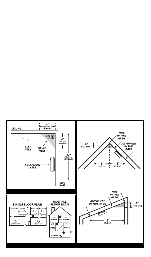
• When mounting an alarm on the ceiling, locate it at a minimum
of 4” (10cm) from the side wall (see figure 1).
• When mounting the alarm on the wall, use an inside wall with
the top edge of the alarm at a minimum of 4” (10cm) and a
maximum of 12” (30.5cm) below the ceiling. (see figure 1).
FIGURE 1
FIGURE 2 FIGURE 3

• Put smoke alarms at both ends of a bedroom hallway or large
room if the hallway or room is more than 30 ft (9.1 m) long.
• Install Smoke Alarms on sloped, peaked or cathedral ceilings at
or within 3ft (0.9m)of the highest point (measured horizontally).
NFPA 72 states: “Smoke alarms in rooms with ceiling slopes
greater than 1 ft in 8 ft (.3m in 2.4m) horizontally shall be located on the high side of the room.” NFPA 72 states: “A row of
alarms shall be spaced and located within 3 ft (0.9m) of the
peak of the ceiling measured horizontally” (see figure 3).
MOBILE HOME INSTALLATION
Modern mobile homes have been designed and built to be energy
efficient. Install smoke alarms as recommended above (refer to
RECOMMENDED LOCATIONS and Figures 1 and 2).
In older mobile homes that are not well insulated compared to
present standards, extreme heat or cold can be transferred from
the outside to the inside through poorly insulated walls and roof.
This may create a thermal barrier which can prevent the smoke
from reaching an alarm mounted on the ceiling. In such units,
install the smoke alarm on an inside wall with the top edge of the
alarm at a minimum of 4” (10cm) and a maximum of 12”
(30.5cm) below the ceiling (see figure 1).
If you are not sure about the insulation in your mobile home, or if
you notice that the outer walls and ceiling are either hot or cold,
install the alarm on an inside wall. For minimum protection, install
at least one alarm close to the bedrooms. For additional protection, see SINGLE FLOOR PLAN in figure 2.
WARNING: TEST YOUR SMOKE ALARM OPERATION AFTER
RV OR MOBILE HOME VEHICLE HAS BEEN IN STORAGE,
BEFORE EACH TRIP AND AT LEAST ONCE A WEEK DURING
USE.
2. LOCATIONS TO AVOID
• In the garage. Products of combustion are present when you
start your automobile.
• Less than 4” (10cm) from the peak of an “A” frame type ceil-
ing.
• In an area where the temperature may fall below 40ºF or rise
above 100ºF, such as garages and unfinished attics.
• In dusty areas. Dust particles may cause nuisance alarm or fail-
ure to alarm.
• In very humid areas. Moisture or steam can cause nuisance
alarms.
• In insect-infested areas.
• Smoke alarms should not be installed within 3 ft (.9m) of the
following: The door to a kitchen, the door to a bathroom containing a tub or shower, forced air supply ducts used for heating
or cooling, ceiling or whole house ventilating fans, or other high
air flow areas.
• Kitchens. Normal cooking may cause nuisance alarms. If a
kitchen alarm is desired, it should have an alarm silence feature
or be a photoelectric type.
• Near fluorescent lights. Electronic “noise” may cause nuisance
alarms.
• Smoke alarms are not to be used with detector guards unless
the combination (alarm and guard) has been evaluated and
found suitable for that purpose.
3. INSTALLATION INSTRUCTIONS
CAUTION: THIS UNIT IS SEALED. THE COVER IS NOT REMOVABLE!
When mounting
in a hallway, the
“A” line should
be parallel with
the hallway.
A
When wall
mounting, the
“A” line should
A
be horizontal.
Alignment Marks
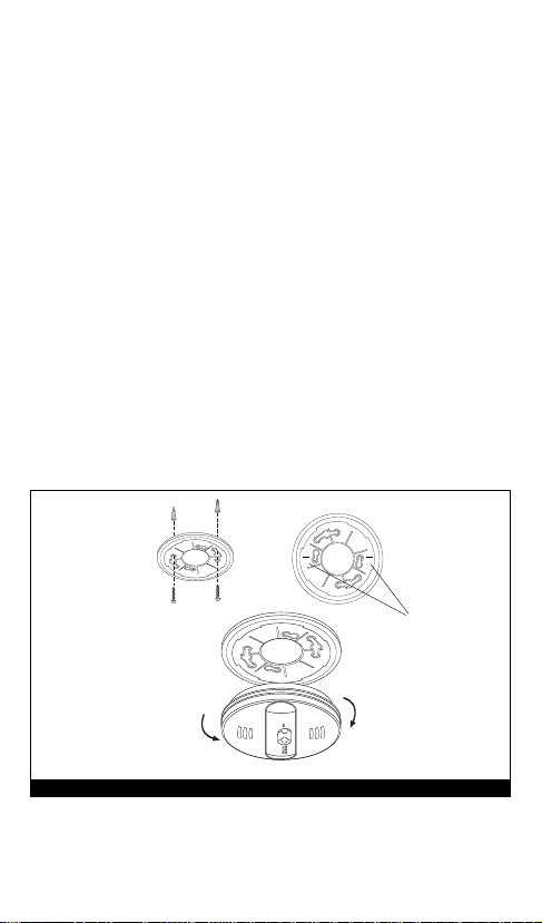
Remove
FIGURE 4
Install
1. Remove the mounting plate from the back of the alarm by hold-
ing the mounting plate and twisting the alarm in the direction
indicated by the “OFF” arrow on the alarm cover.

Battery
Reminder
Finger
FIGURE 5
2. To insure aesthetic alignment of the alarm with the hallway or
wall, the “A” line on the mounting plate should be parallel with
the hallway when ceiling mounting or horizontal when wall
mounting.
3. After selecting the proper smoke alarm location as described in
section 1, attach the mounting plate to the ceiling as shown in
figure 4. For wall mounting see figure 4. Place mounting plate
on the wall. Be sure the “A” line is horizontal. Use the screws
and anchors provided to secure the mounting plate (use 3/16”
drill bit for anchor holes).
4. Battery installation instructions are provided on the inside of the
battery door.
To ensure proper installation of the smoke alarm battery, follow
the instructions.
5. When installing the battery, press the battery reminder finger
down into the battery compartment and install the battery (see
figure 5).
CAUTION! IF THE BATTERY REMINDER FINGER IS NOT HELD
DOWN IN THE BATTERY COMPARTMENT BY THE BATTERY,
THE BATTERY DOOR WILL NOT CLOSE AND THE UNIT WILL
NOT ATTACH TO THE MOUNTING BRACKET.
6.Install the alarm on the trim ring and rotate the alarm in the direc-
tion of the "ON" arrow on the cover until the alarm ratchets into
place (this ratcheting function allows for aesthetic alignment).
TAMPER RESIST FEATURE: To make your smoke alarm tamper
resistant, a tamper resist feature has been provided. Activate the
tamper resist feature by breaking off the four posts in the square
holes in the trim ring (see figure 6). When the posts are broken
off, the tamper resist tab on the base is allowed to engage the
mounting bracket. Rotate the alarm onto the trim ring until you
hear the tamper resist tab snap into place, locking the alarm on
the trim ring. Using the tamper resist feature will help deter chil-
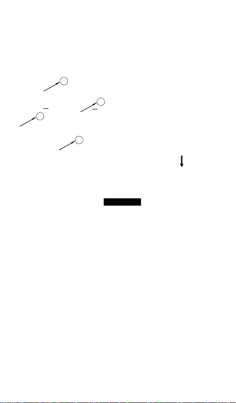
dren and others from removing the alarm from trim ring. NOTE: To
remove the alarm when the tamper resist tab is engaged, press
down on the tamper resist tab, and rotate the alarm off of the
trim ring (see figure 6).
After installation, test your alarm by depressing and holding down
the test button for at least 5 seconds. This should sound the alarm.
A
Posts
A
FIGURE 6
4. OPERATION AND TESTING
OPERATION: The smoke alarm is operating once a fresh battery is
installed and testing is complete. When products of combustion
are sensed, the unit sounds a loud 85db pulsating alarm until the
air is cleared.
HUSH CONTROL: The “HUSH” feature has the capability of temporarily desensitizing the alarm circuit for approximately 8 minutes.
This feature is to be used only when a known alarm condition,
such as smoke from cooking activates the alarm. The smoke alarm
is desensitized by pushing the “HUSH” button on the smoke alarm
cover. If the smoke is not too dense, the alarm will silence immediately and the red LED will flash every 2 seconds for approximately
8 minutes. This indicates that the alarm is in a temporarily desensitized condition. The smoke alarm will automatically reset after
approximately 8 minutes, and sound the alarm if smoke is still
present. The “HUSH” feature can be used repeatedly until the air
has been cleared of the condition causing the alarm. Pushing the
test/reset button on the alarm will end the hush period.

NOTE: DENSE SMOKE WILL OVERRIDE THE HUSH CONTROL
FEATURE AND SOUND A CONTINUOUS ALARM.
CAUTION: BEFORE USING THE ALARM HUSH FEATURE, IDENTIFY THE SOURCE OF THE SMOKE AND BE CERTAIN A SAFE
CONDITION EXISTS.
LED INDICATOR: This smoke alarm is equipped with a red LED indicator. The red LED is located under the test button and has several
modes of operation.
Standby Condition: The red LED will flash every 30-40
Alarm Condition: When the alarm senses products of
Hush Condition: The red LED will flash every 2 seconds as
Low Battery Condition: The red LED flash will be accompanied
SMOKE SENSING CHAMBER OPERATION: This alarm will “chirp” if
any of the components in the smoke sensing chamber fail. This
chirp will occur between the flashes of the red LED indicator light.
(If the chirp occurs at the same time as the red LED flash, see section 6 for low battery information).
TESTING: Test by pushing the test button on the cover and hold it
down for a minimum of 5 seconds. This will sound the alarm if the
electronic circuitry and horn and battery are working. If no alarm
sounds, the unit has defective batteries or other failure. DO NOT
use an open flame to test your alarm, you could damage the
alarm or ignite combustible materials and start a structure fire.
Alarm Memory: This smoke alarm is equipped with an alarm
seconds to indicate that the smoke
alarm is operating properly.
combustion and goes into alarm, the
red LED will flash rapidly (once every
two seconds). The rapid flashing LED
and temporal alarm will continue until
the air is cleared.
long as the alarm is in Hush mode.
by an audible chirp. Replace the battery
when this condition occurs.
memory feature which produces a rapid
chirping sound when the test button is pushed.
This sound indicates that the alarm has been
activated since it was last tested. Releasing the
test button clears the memory. If the alarm
memory sound is heard, release the test button
 Loading...