


 Loading...
Back |
|
Exit |
|
|
|
|
|
|
VEGA LT
INSTALLATION
AND
COMMISSIONING
MANUAL
TM0081
PROPRIETARY RIGHTS NOTICE
The information contained in this manual is the property of Kidde Fire Protection Services Limited and may not be reproduced or transmitted in any form or by any means, electronic, mechanical, photocopying, recording or otherwise, nor stored in any retrieval system of any nature without the express written authority of Kidde Fire Protection Services Limited.
© Copyright 2003 Kidde Fire Protection Services Ltd
TM0081 |
Page 1 of 51 |
Issue 1.01 |
|
TABLE OF CONTENTS |
|
1. |
INTRODUCTION ........................................................................................................................................ |
4 |
1.1 |
DESCRIPTION ........................................................................................................................................... |
4 |
1.2 |
ABOUT THIS MANUAL .............................................................................................................................. |
5 |
1.3 |
SYSTEM DESIGN ...................................................................................................................................... |
5 |
1.4 |
ELECTRICAL SAFETY............................................................................................................................... |
5 |
2. |
GLOSSARY OF TERMS AND ABBREVIATIONS...................................................................................... |
6 |
3. |
INSTALLATION .......................................................................................................................................... |
7 |
3.1 |
SYSTEM SCHEMATIC ............................................................................................................................... |
7 |
3.2 |
APPROVED CABLES................................................................................................................................. |
8 |
3.3 |
INTERNAL CABLE ROUTING.................................................................................................................... |
8 |
3.4 |
ENCLOSURE MOUNTING......................................................................................................................... |
9 |
3.5 |
EXTERNAL CONNECTIONS ................................................................................................................... |
10 |
3.5.1 |
Mains Wiring ............................................................................................................................................. |
10 |
3.5.2 |
Detection Loop Wiring............................................................................................................................... |
10 |
3.5.3 |
Sounder Circuit Wiring .............................................................................................................................. |
12 |
3.5.4 |
Auxiliary Output Wiring ............................................................................................................................. |
12 |
3.5.6 |
Auxiliary Input Wiring ................................................................................................................................ |
13 |
3.5.7 |
Battery Installation .................................................................................................................................... |
14 |
3.5.8 |
Network and Repeater Cable Wiring ........................................................................................................ |
14 |
4. |
ACCESS CONTROL LEVELS.................................................................................................................. |
15 |
4.1 |
ACCESS INHIBIT KEYSWITCH............................................................................................................... |
15 |
5. |
CONTROLS AND INDICATION ............................................................................................................... |
16 |
5.1 |
PANEL DISPLAY ...................................................................................................................................... |
16 |
5.2 |
CONTROL BUTTON FUNCTIONS .......................................................................................................... |
16 |
5.3 |
STATUS WINDOW INDICATION ............................................................................................................. |
17 |
5.4 |
LIQUID CRYSTAL DISPLAY LAYOUT..................................................................................................... |
17 |
6. |
OPERATION............................................................................................................................................. |
18 |
6.1 |
STATUS NORMAL ................................................................................................................................... |
18 |
6.2 |
GAINING ACCESS TO LEVEL 2 OR 3 .................................................................................................... |
18 |
6.2 |
FIRE CONDITION..................................................................................................................................... |
18 |
6.3 |
RESETTING THE SYSTEM AFTER A FIRE CONDITION ...................................................................... |
20 |
6.4 |
FAULT CONDITIONS............................................................................................................................... |
20 |
6.4.1 |
System Faults ........................................................................................................................................... |
20 |
6.4.2 |
Zone Fault Conditions............................................................................................................................... |
21 |
6.4.3 |
Group Fault Conditions ............................................................................................................................. |
22 |
7. |
PRIORITY ALARM STRUCTURE ............................................................................................................ |
23 |
8. |
FIRE & PLANT ZONE INDICATIONS ...................................................................................................... |
23 |
9. |
MENU STRUCTURE ................................................................................................................................ |
23 |
9.1 |
MAIN MENU ............................................................................................................................................. |
23 |
9.2 |
ISOLATE \ DE-ISOLATE MENU............................................................................................................... |
24 |
9.3 |
LIST MENU............................................................................................................................................... |
25 |
9.4 |
SET MENU ............................................................................................................................................... |
26 |
9.5 |
TEST MENU ............................................................................................................................................. |
27 |
10. |
COMMISSIONING .................................................................................................................................... |
28 |
10.1 |
SYSTEM CHECKS ................................................................................................................................... |
28 |
10.2 |
INITIAL POWER UP ................................................................................................................................. |
28 |
10.3 |
POWERING DOWN ................................................................................................................................. |
29 |
10.4 |
CONNECTING THE DETECTION LOOP................................................................................................. |
29 |
10.5 |
ADDING OR REMOVING LOOP DEVICES............................................................................................. |
29 |
10.5.1 |
Power Down.............................................................................................................................................. |
29 |
10.5.2 |
Processor Restart ..................................................................................................................................... |
30 |
10.5.3 |
Auto Learn ................................................................................................................................................ |
30 |
10.6 |
CONNECTING SOUNDER CIRCUITS..................................................................................................... |
30 |
11. |
PROGRAMMING STANDARD & CUSTOM FEATURES......................................................................... |
31 |
11.1 |
PANEL SET-UP ........................................................................................................................................ |
31 |
11.2 |
ZONE FIRE INFORMATION .................................................................................................................... |
32 |
11.3 |
LOOP DEVICE INFORMATION ............................................................................................................... |
32 |
11.4 |
PANEL FUNCTIONS (STANDARD OR BLC OUTPUTS) ........................................................................ |
34 |
11.5 |
OUTPUT GROUP INFORMATION........................................................................................................... |
34 |
11.5.1 |
Fire Output ................................................................................................................................................ |
35 |
11.5.2 |
Isolate Output Group................................................................................................................................. |
35 |
TM0081 |
Page 2 of 51 |
Issue 1.01 |
11.6 |
SET ACTIVATIONS .................................................................................................................................. |
35 |
11.6.1 |
Common Alarm Installations..................................................................................................................... |
35 |
11.6.2 |
Zone by Zone Alarm Installations ............................................................................................................. |
36 |
11.6.3 |
Activation Styles........................................................................................................................................ |
37 |
11.6.4 |
Zone and Output Group Timers................................................................................................................ |
37 |
11.6.5 |
Single Device to Output Group Programming .......................................................................................... |
38 |
11.6.6 |
Plant Alarm to Output Group Programming.............................................................................................. |
38 |
11.7 |
REPEATER INFORMATION .................................................................................................................... |
39 |
11.8 |
MOTHERBOARD INFORMATION ........................................................................................................... |
39 |
11.9 |
PRIORITY HEADER TEXT....................................................................................................................... |
39 |
11.10 |
CUSTOM DEVICE TEXT.......................................................................................................................... |
39 |
11.11 |
PLANT ALARM INFORMATION............................................................................................................... |
40 |
11.12 |
NETWORK INFORMATION ..................................................................................................................... |
40 |
12 |
PLUG IN OPTIONS – INSTALLATION AND COMMISSIONING............................................................. |
41 |
12.1 |
VEGA LOOP CARD - Part Number 44782-K074 ..................................................................................... |
41 |
12.2 |
REPEATER CARD - Part Number 44782-K076....................................................................................... |
42 |
12.3 |
PRINTER ASSEMBLYPart Number VR0053......................................................................................... |
43 |
12.4 |
VEGANET NETWORK CARD - Part Number VN2107 ............................................................................ |
44 |
12.5 |
CZN NETWORK CARD - Part Number VN2108 ...................................................................................... |
46 |
13 |
MAINTENANCE........................................................................................................................................ |
47 |
13.1 |
ROUTINE MAINTENANCE....................................................................................................................... |
47 |
13.2 |
TEST MODE ............................................................................................................................................. |
47 |
14. |
PANEL AND LOOP DEVICE FAULT CODES.......................................................................................... |
48 |
15. |
FAULT DIAGNOSIS.................................................................................................................................. |
49 |
16. |
RECOMMENDED SPARES LIST............................................................................................................. |
50 |
17. |
TECHNICAL SPECIFICATION................................................................................................................. |
51 |
TM0081 |
Page 3 of 51 |
Issue 1.01 |
1.INTRODUCTION
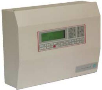
This manual covers the Vega LT2000 and LT2001 Control Panel. The Vega LT fire control panel provides analogue addressable detection of fire and is compatible with devices manufactured by Apollo and Hochiki. Designed to comply with EN54: parts 2 & 4, the Vega LT provides a single detection loop and can cover 16 zones. The panel is mains powered and also has space for two 12 amp-hour standby batteries (not supplied) A range of optional equipment is available to enhance the panel’s standard, fixed format configuration.
The Vega LT2000 provides support for Apollo series 90,95, Discovery and Explorer detectors and the Vega LT2001 supports the Hochiki ESP range of detectors. Both versions of control panel provide the following key features: -
!Single detection loop
!Two conventional programmable sounder circuits
!Two auxiliary volt free programmable relay contacts
!Fault volt free relay contact
!Four auxiliary input connections
!Membrane control fascia
!8 system status indications
!16 zone indications
!8 line – 40 character liquid crystal display
!Integral 2.5 amp power supply unit
!Battery back-up facility
Figure 1: Vega LT Fire Control Panel
1.1DESCRIPTION
The Vega LT consists of a backbox with 20 mm knockouts for cable entry and has a hinged, removable door which is retained with a locking screw and incorporates the panel display membrane. The panel display has 16 zonal windows, status windows, user control and a liquid crystal display. The backbox has a keyhole locating hole for positioning and can be secured through the four 4 mm indented holes located near each corner. Refer to Figure 1.
A range of optional add-ons can be supplied separately and installed during commissioning to enhance the systems capabilities. These options include: -
!Loop card – to extend the panel to a maximum of two detection loops.
!Repeater driver card – enables the Vega LT to communicate with VR3000 repeater panel(s)
!Event printer – 24 character, thermal type. VR0053.
!Network interface – provides communication to VegaNET graphics display system. VN2107.
!Network interface – provides communication to Common Zone Network CZN System. VN2108.
TM0081 |
Page 4 of 51 |
Issue 1.01 |
1.2ABOUT THIS MANUAL
This installation manual details how to install and commission the Vega LT fire control panel and range of optional equipment. It has been carefully checked for accuracy and is presumed to be correct. The manufacturer assumes no responsibility for inaccuracies and reserves the right to modify the contents without notice.
1.3SYSTEM DESIGN
The design of the fire detection and alarm system should be in accordance with BS 5839 part 1 Fire detection and fire alarm systems for buildings -“Code of practice for system design, installation, commissioning and maintenance” and may be supplemented with customer’s specific installation requirements. The fire alarm system design is beyond the scope of this document. It is therefore assumed that a basic knowledge of general fire alarm system practices, components and their use is understood.
We recommend that a suitably qualified and competent person is consulted in connection with the design of the fire alarm system and that the system is commissioned and services in accordance with the laid down specification and national standards.
The Fire Officer responsible for the property should be contacted at an early stage to discuss of any site-specific requirements.
1.4ELECTRICAL SAFETY
Before handling any part of the control panel, ensure that adequate precautions are taken against damage to the sensitive electronic components located within the control panel. Operators and engineers should discharge themselves of any personal electro-static charge by momentarily touching a convenient earthed object.
Static charges are collected on adjacent conductors and are delivered in the form of sparks passing between the conductors through insulating space or material. The sweat layer on the human skin is a sufficient medium to store induced static charges and deliver them to any receptive conductor such as an electronic component or printed circuit board. Following these guidelines can reduce static discharges:
!Always use conductive or anti-static containers for transportation and storage.
!Wear an earth wrist strap whilst handling devices, ensuring a good earth connection is maintained.
!Never subject a static sensitive device to sliding movement over any surface and avoid any direct contact with the pins.
!Avoid placing sensitive devices onto plastic or vinyl surfaces.
!Minimise the handling of sensitive devices and printed circuit boards.
All static sensitive devices are marked accordingly, but it is good engineering practice to treat all components and boards with the same degree of protection.
WARNING:
The static handling procedures must be adhered to and extreme caution must be exercised when working inside the control panel due to the presence of mains voltage 230 V AC. Failure to do so may invalidate product warranty.
TM0081 |
Page 5 of 51 |
Issue 1.01 |
2.GLOSSARY OF TERMS AND ABBREVIATIONS
Abbreviation |
Translation |
Description |
MCP |
Main Control Processor |
Part number 44782-K071, the MCP card is located on the |
|
|
back of the outer door and is responsible for controlling the |
|
|
LCD Display, event printer, LED indications, reading in the |
|
|
control button key actions, VIPER upload \ download |
|
|
software. The card is also responsible for communicating |
|
|
with BLC loop processor cards, repeater output ports and |
|
|
network cards. |
BLC |
Basic Loop Controller |
There are two types of BLC cards, the master and slave. |
MBLC |
Master Basic Loop Controller |
Part number 44782-K073, the MBLC card is responsible for |
|
|
communicating externally with detection loops 1 and 2. The |
|
|
card also provides 2 monitored sounder circuits, 2 auxiliary |
|
|
VFCO contacts & a failsafe fault VFCO contact. The MBLC |
|
|
card also provides connections to the repeater and network |
|
|
interface cards. |
SBLC |
Slave Basic Loop Controller |
Not applicable on Vega LT |
CCT |
Circuit |
Reference to loop or sounder monitored circuitry. |
SND |
Sounder |
|
VFCO |
Voltage Free Change Over |
Also known as dry contact |
PCB |
Printed Circuit Board |
|
BGU |
Break Glass Unit |
Also known as Manual Call Point |
EMC |
Electro Magnetic Compatibility |
|
EOL |
End of Line |
EOL monitoring device used on sounder circuits |
LED |
Light Emitting Diode |
|
PSU |
Power Supply Unit |
|
LCD |
Liquid Crystal Display |
|
SLA |
Sealed Lead Acid |
Type of battery used within fire control panels |
Cause & Effect |
|
Operation of programmable outputs and functions as a |
|
|
result of an event being registered. |
I/O |
Input / Output |
|
PC |
Personal Computer |
|
mA |
Milli amp |
|
BS |
British Standard |
|
EN |
European Norm |
|
Ah |
Amperes Hour |
|
dB (A) |
Decibel |
|
IP |
Ingress Protection |
|
mΩ |
Milli ohm |
|
KΩ |
Kilo ohm |
|
Comms |
Communications |
Communications abbreviated to fit display |
Config |
Configuration |
Configuration abbreviated to fit display |
|
|
|
TM0081 |
Page 6 of 51 |
Issue 1.01 |

3.INSTALLATION
Installation of the fire detection and alarm system must comply with the current editions of:
!The IEE wiring regulations.
!The British Standard for Fire Detection and Alarm Systems for buildings BS 5839: part 1
!Local country legislation if outside of the United Kingdom.
Take care not to install the cables in the proximity of high voltage cables or in areas likely to induce electrical interference. Junction boxes should be avoided, but if they have to be installed then they must be clearly labelled "FIRE ALARM".
Special attention should be made in the selection of loop wiring conductor size to ensure that the voltage drop does not prevent devices operating within their specification even under minimum supply and maximum load conditions. Consideration should also be given for future expansion of the system.
It is not permissible to run more than one detection loop in single cable, but a four-core cable can be used for the feed and return of an individual loop. However, to increase the integrity of the loop it is recommended that the feed and return cable pairs use different paths around the building.
It is not permissible to run any other circuits in the same cable as a detection loop, i.e. sounder circuits, power supplies, plant shut downs etc, as the induction capacities of the cable can cause corruption of loop information and/or inter-loop "cross talk".
3.1SYSTEM SCHEMATIC - Figure 2
Figure 2: System Schematic Diagram
The control panel has a number of internal 2.5mm terminals for connection to the external field cables.
TM0081 |
Page 7 of 51 |
Issue 1.01 |
3.2APPROVED CABLES
To comply with EMC (Electro Magnetic Compatibility) regulations and to reduce the risk of electrical interference in the system wiring, it is recommended that screened cables be used throughout the installation. Reference to BS 5839 part 1, states there is two categories of cable,
!Category 1: required to operate for prolonged periods during a fire condition
!Category 2: not required to operate for prolonged periods during a fire condition
Cables complying to BS 6387 categories C,W, Z can be used for both categories 1 and 2, Cables deemed suitable as Category 1 can be used as category 2, but not visa versa. The following commonly available screened cables have been approved for use on sounder and detection circuits:
!Pirelli FP200 Gold™
!MICC (Pyro™)
!Firetuff™
!Firecel™
Connection to the Kidde network and repeater panels should be made using Beldon 9729, UL2493 or MICC. Satisfactory operation of the system with inferior cable types cannot be guaranteed especially when not wired in accordance with to the appropriate regulations, i.e. loop wiring run in proximity to high voltage (AC mains and above) cabling.
3.3INTERNAL CABLE ROUTING
It is important that the following procedures on internal cable routing and cable terminations inside the control panel are adhered to fully. These procedures have been established to ensure the control panel complies with the European Directive on Electromagnetic Compatibility (89/336/EEC).
The external cables must be kept to an absolute minimum length from the cable entering the enclosure to the terminating position on the relevant printed circuit board. Special attention should be made to ensure that cables do not cross over other cables where possible, as this may generate interference/electrical noise.
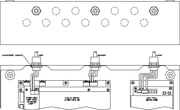
The detection loop and sounder circuit cabling is classed as Low Voltage and should be segregated from mains voltages. The pre-formed knockouts shown in figure 3 must be carefully removed, where required, using a flat broad-bladed screwdriver and hammer. Use of excessive force should not be required and may damage the enclosure around the knockout. The surrounding paint must be carefully removed to permit metal to metal contact between the enclosure and cable gland.
Figure 3: Knockouts and Cable Routing
TM0081 |
Page 8 of 51 |
Issue 1.01 |

Care must be taken to ensure metal filings or swarf does not fall onto the printed circuit boards. An adequate number of pre-formed knockouts have been provided on the top of the enclosure so there should be no requirement to drill any additional holes. Ensure that if a knockout is removed and unused, that the hole is filled with a good quality cable gland that is securely blanked off.
3.4ENCLOSURE MOUNTING
The control panel should be installed within the building to be protected at a prominent location and at a height where it can be easily accessed during an emergency. The control panel should ideally be located in the entrance, foyer or hallway of the building at eye level. The panel should not be positioned where conditions may affect its performance. Areas prone to salt air, moisture, high humidity, physical abuse, and extreme temperatures should be avoided.
Remove the control panel from its packing and unlock the door using the Allen Key provided.
Note, A spare parts bag is not provided with this control panel. Battery leads and End of Line resistors are factory fitted to the associated output terminals. A spare sounder fuse is provided. Refer figure 2 for location.
Hold the panel to the wall at the desired mounting height and mark the position of the top centre keyhole. The enclosure fixing positions are shown in figure 4. The keyhole is provided on the backbox to allow the panel to be hooked onto the wall whilst the remaining four screws are located, marked and drilled accordingly. Secure the panel to the wall using suitable fixings such that adequate support is provided.
Figure 4: Enclosure Fixing Positions
TM0081 |
Page 9 of 51 |
Issue 1.01 |
3.5EXTERNAL CONNECTIONS
3.5.1Mains Wiring
The Vega LT control panel receives power from either a 230V, 50Hz or 120V, 60Hz power supply. The mains supply cable must take the shortest route possible from entering the enclosure to the mains supply terminals. Refer figure 5. The cable must maintain an air gap of 50mm minimum between it and any other conductors.
The mains supply requirement for the fire alarm panel is fixed wiring, using three core cable (no less than 0.75mm² and no more than 2.5mm²) or a suitable three conductor system and should be fed from an isolating switched fused spur rated at 5amp. The fused spur isolator cover should be red and marked: FIRE ALARM – DO NOT SWITCH OFF. The fused spur isolator must be fed from a dedicated switch or protective device at the local mains supply distribution board.
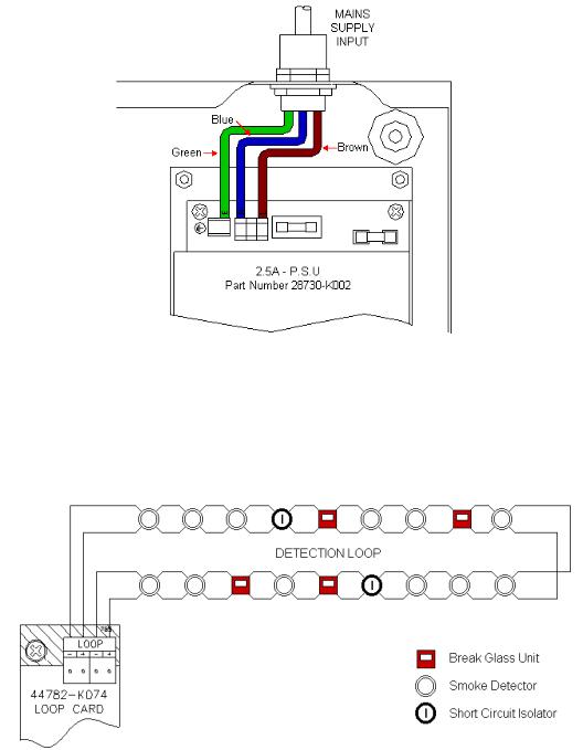
The incoming power feed cable Earth (Green or Green/Yellow) wire should be connected to the terminal block earth connection – Left hand terminal. The Neutral (Blue) wire should be connected to the middle terminal marked (N) and the Live (Brown) wire connected to the right hand terminal marked (L). Refer to Figure 5.
Figure 5: Mains Supply Input
3.5.2Detection Loop Wiring
The external detection circuit wiring should be wired to form a loop to allow the system to maintain a degree of integrity and still function even if a section of cable becomes open circuit. It is also recommended during the system design that short circuit isolators are fitted to the detection loop, so that in the event of an external short circuit no more than 32 addressable devices will be lost. Refer to Figure 6.
Figure 6: Typical Loop Wiring
TM0081 |
Page 10 of 51 |
Issue 1.01 |
The detection loop connections are made on the Loop card terminals marked LOOP. The loop card has built in isolators so it is not required to fit additional isolators directly on the loop output. Additional short circuit isolators should be fitted at the boundaries of each fire zone.
Reference should be made to the detector manufacturer’s data sheets and installation guides supplied with the detector or module for information on terminal connection etc. Ensure that the devices connected to the detection loop wiring are correctly orientated for positive and negative connections.
The detection loop cable must be stripped in accordance with the manufacturer's guidelines. The cable must be secured to the enclosure using metal compression glands and metal locking nuts in conjunction with a metal shake proof washer to ensure that the cable metal sheath is bonded to the enclosure. Refer to figure 7.
Figure 7: Loop and Sounder Circuit Compression Gland Details
When all bases are connected but before any devices are installed and with loop isolators linked out, the following tests should be carried out: -
!Loop short-circuit. Using an ohmmeter, check for short-circuit between +ve and -ve feeds.
!Loop open-circuit. Check continuity of the +ve and -ve leads. +ve to +ve and –ve to –ve.
!Loop short to earth. Check using an ohmmeter between the +ve and -ve leads and an earth connection.
Warning.
Do not undertake high voltage insulation testing on external wiring after loop devices are installed as this could seriously damage the equipment.
TM0081 |
Page 11 of 51 |
Issue 1.01 |
3.5.3Sounder Circuit Wiring
Two programmable conventional sounder circuits are available on the control panel. Each circuit is rated at 1amp however it is recommended that the maximum total load shared between both circuits should not exceed 1amp. Each sounder circuit is monitored for open and short circuits. An end of line (EOL) 10 KΩ resistor 0.5W minimum should be fitted after the last sounder attached to the circuit to allow the wiring to be monitored.
All sounders must be polarised, as non-polarised sounders will signal a fault condition on the control panel. Refer to figure 8. Each sounder therefore must have an integral blocking diode that prevents the sounder from using power during normal monitoring. The polarity of the sounder output voltage is reversed when the sounder circuit is operated allowing the sounders devices to operate.
Figure 8: Typical Polarised Sounder Circuit Wiring
Should non polarised alarm devices such as mechanical bells be connected to the system, then a diode will have to be placed in line with the device to prevent faults occurring and to enable fault monitoring. A suppression diode will also be required across the device. Refer to Figure 9.
Figure 9: Typical Bell Circuit Wiring
The sounder circuit cable must be stripped in accordance with the manufacturer's guidelines and must be secured to the enclosure using metal compression glands as shown in figure 7.
3.5.4Auxiliary Output Wiring
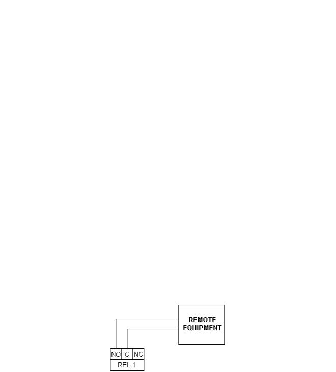
Auxiliary Fire Output
Two voltage free (dry contact) changeover contacts are provided which operate during any fire condition and can be used for driving local fire fighting equipment such as sprinkler systems, door release systems and roller shutter doors etc. Refer to Figure 10.
Figure 10: Typical Auxiliary Fire Output Wiring
TM0081 |
Page 12 of 51 |
Issue 1.01 |
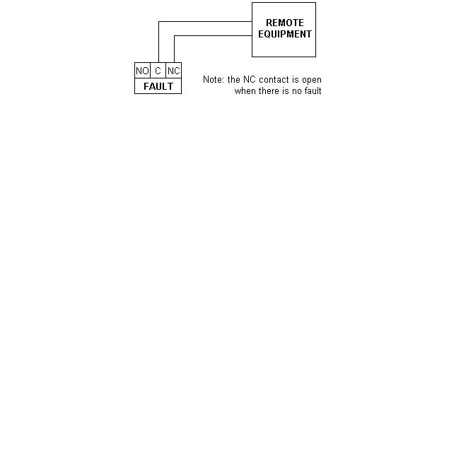
Auxiliary Fault output
A single voltage free changeover contact is provided and operates on any panel fault condition. This output is failsafe and is normally energised. When a fault occurs, the output turns off to ensure failsafe operation, or should the system suffer a failure to all power supplies. Refer to Figure 11.
Figure 11: Typical Auxiliary Fault Output Wiring
External cables connected to the auxiliary contacts should be secured to the enclosure using metal compression glands as shown in figure7.
3.5.6Auxiliary Input Wiring
Four non-latching input connections are available on the fire alarm panel. The inputs are located on the loop processor card, part number 44782-K073 at terminal block TB7. Applying a 0-volt connection to the terminal activates the inputs. Refer to Figure 12. The inputs are provided at the following terminal numbers: -
1 External Fault Input
2 Level 2-access/inhibit override
3 Programmable Input A
4 Programmable Input B
The programmable input settings are:
!Remote Alarm (Class Change): operates the sounders continuously (default setting for input A) or
!Day Mode: initiates pre programmed day mode settings (default setting for input B) or
!Isolate Outputs: inhibits the operation of pre-programmed isolation group setting
Figure 12: Typical Auxiliary Input Wiring
Cables connected directly to the auxiliary inputs should not be taken external to the control panel. Interposing relays located within interface enclosures and mounted directly adjacent to the control panel should be used.
TM0081 |
Page 13 of 51 |
Issue 1.01 |
3.5.7Battery Installation
To provide an emergency battery back up facility in the event of mains failure for the system, two new fully charged 12 volt sealed lead acid batteries are required. The batteries should be connected in series using the battery leads connected to the power supply unit and should be located in the bottom left hand corner of the control panel enclosure. The enclosure has space for 2x 12 Ah SLA batteries. The capacity of the batteries used will depend upon the required stand-by time and the system configuration. For battery sizes greater than 12 Ah these should be installed in a separate enclosure suitable for fire protection equipment using appropriate metal gland fixings and cables.
Before installing the batteries carry out the following procedures:
!Check the batteries for transit damage.
!Check the battery open circuit terminal voltage.
!Record the installation date.
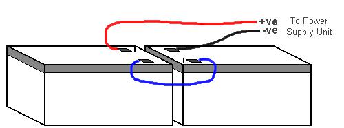
The +ve of one battery is connected to the red battery lead and the –ve of the second battery is connected to the black battery lead. The –ve of the first battery is connected to the +ve of the second battery using the battery link supplied. Refer to Figure 13.
Figure 13: Internal Battery Connections
CAUTION:
Do not connect the batteries to the power supply unit leads at this stage.
The control panel power supply unit has a thermistor, which monitors the temperature of the batteries and automatically adjusts the charging current accordingly. This should be placed as close as possible to the first battery.
3.5.8Network and Repeater Cable Wiring (Optional)
When connecting to optional network and repeater wiring, the outer insulating sheath of the cable must be removed using a proprietary cable stripper. This will expose a number of cable pairs, which will be individually wrapped in a protective sheath. This sheath must be folded back over the remaining outer insulating sheath and the metallic compression gland to ensure that the protective metallic sheath has a permanent bonding to the enclosure. The compression gland must be secured to the enclosure using a metal locking nut in conjunction with a metal shake proof washer.
TM0081 |
Page 14 of 51 |
Issue 1.01 |
4.ACCESS CONTROL LEVELS
The Vega LT has four levels of system control. Refer to Table 1. The control panel will indicate the true status condition of the installation during all four levels using the membrane display panels. Pass codes are entered on the numeric keypad. Each operation of the keypad operates an internal buzzer and updates the liquid crystal display to confirm entry.
Access |
Operating |
Default Pass |
Comments |
Level |
Level |
Code |
|
1 |
Normal |
N/A |
Control buttons inhibited. During an alarm condition certain |
|
operation |
|
control buttons are functional. |
2 |
User |
7179 |
All control buttons are functional with restricted menu |
|
|
|
access. System configuration inhibited. |
3 |
Engineer & |
7134 |
All control buttons are functional, All menu levels become |
|
Installer |
|
available and system configuration is possible. |
4 |
Kidde |
N/A |
As level 3 with option to clear panel memory back to factory |
|
Engineer |
|
default setting. |
Table 1: Access Levels
The operation of the control panel is dependent upon the selected pass code, as certain keys only operate in specific access levels. Table 2 details the control keys and the access levels they are allowed to operate in.
Control Button |
Access Level 1 |
Access Levels 2&3 |
Numeric Keys |
" |
" |
Cancel (← ) |
" |
" |
Enter ( ) |
" |
" |
Arrow Keys |
" |
" |
Silence Buzzer |
" |
" |
Scroll |
" |
" |
Delay Override |
" |
" |
Silence Alarms |
- |
" |
Reset |
- |
" |
Evacuate |
- |
" |
Table 2: Control buttons
4.1ACCESS INHIBIT KEYSWITCH
An input terminal (TB7) labelled input 6 is positioned on Master Basic Loop Controller MBLC card (refer to Figure 12 for wiring information) which when shorted to 0-volts, via a switch, causes the control panel to enter into access level 2. Only by removal of the 0-volt input to the terminal will the access level be terminated.
TM0081 |
Page 15 of 51 |
Issue 1.01 |
5.CONTROLS AND INDICATION
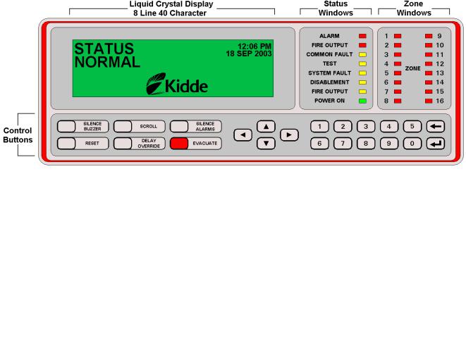
5.1PANEL DISPLAY
The Vega LT front panel display is divided into four discrete sections containing the control buttons, zone windows, status windows and liquid crystal display (LCD). Refer to Figure 14.
Figure 14: Front Panel Display
5.2CONTROL BUTTON FUNCTIONS
The control buttons located on the panel front perform a number of operations. Refer to Table 3.
Control Button |
Function |
Numeric Keys |
Allows the user to enter numbers 0 – 9. |
Cancel (← ) |
Allows the user to answer No, quit menu display options or terminate access levels 2 & 3 |
|
completely. |
Enter ( ) |
Allows the user to answer Yes, enter menu display options, and confirm input for numeric |
|
information. |
Arrow Keys |
Allows the user to scroll through menu display options, active alarm messages and view |
|
priority pending alarm messages. Also used during programming of the control panel. |
|
|
Silence Buzzer |
Silences the internal buzzer for any fire or fault alarm condition. |
Scroll |
Press to display the next alarm message at the current event level. |
Delay Override |
Overrides any pre-programmed delays and immediately operates the outputs. |
Silence Alarms |
Press to turn off All sounder circuits |
Reset |
Press to cancel All fire & fault alarm conditions and reset the system back to normal. |
Evacuate |
Press to turn on All sounder circuits and evacuate the building. |
|
Table 3: Control Button Functions |
TM0081 |
Page 16 of 51 |
Issue 1.01 |
Loading...