

Page 1

KS
KSCOMPONENTSYSTEM
KS650.2, KS60.2, KS50.2
©2007 Stillwater Designs
Page 2
Your KS components were specially designed for “Livin’ Loud” out in the harsh automotive
environment. They are made of advanced materials and construction techniques to
maintain optimal performance for years to come.
Application
The Kicker KS components are specifically designed for mounting in free-air applications.
The speakers do not require a sealed enclosure for optimum performance. It is important to
isolate the sound coming off the front of the driver from the sound radiating from the back
of the driver. This isolation is usually accomplished by using the driver in a factory speaker
location, or in a location with a semi-isolated rear chamber. See Figure 1.
Location
The sound produced by the KS components is directional, particularly for the tweeter’s
sonic output. The external crossover has a three position (0, 3, and 6dB) High Frequency
Output Level switch that allows for added flexibility in positioning the tweeter. Find the best
location for stereophonic sound. If necessary, add more KS component systems or coaxial
speakers to the audio system to help distribute and balance the sound. After determining
the best mounting locations, carefully check the areas where the mounting hardware will be
placed. See Figure 2.
INSTALLATION
Congratulations on your
KICKER purchase
Please record your purchase
information and keep your sales
receipt for validation of warranty.
Authorized Kicker Dealer:
Purchase Date:
Speaker Model Number:
_________________________
_________________________
_________________________
Note: All specifications and performance figures are subject to change. Please visit the www.kicker.com for the most current information.
To get the best performance from your new Kicker speakers, we recommend using genuine Kicker Accessories and Wiring.
Please allow two weeks of break-in time for the speaker to reach optimum performance.
2
INSTALLATION
KSComponentSystem
Owner’sManual
KS650.2 / KS60.2 / KS50.2
Models:
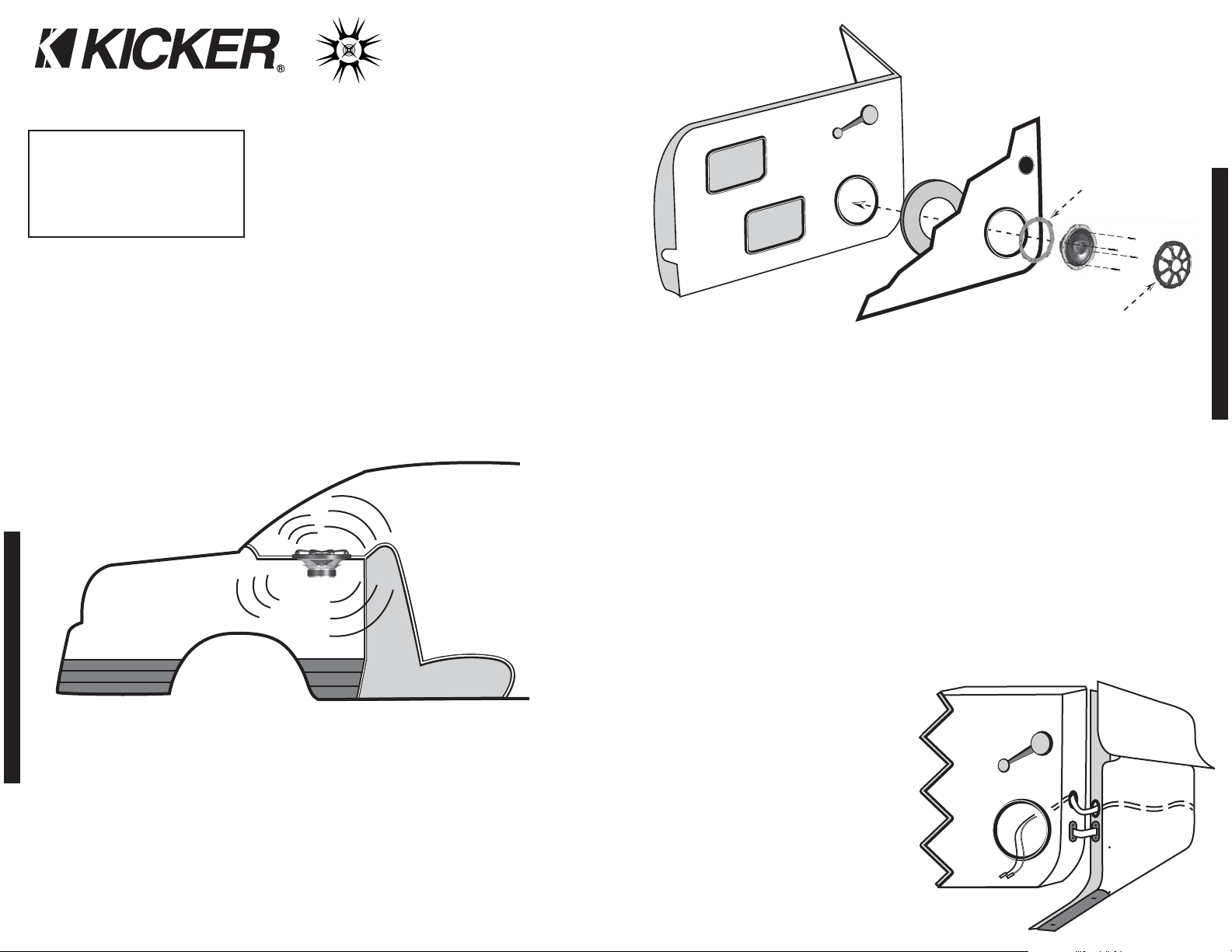
WooferMounting
If you are replacing factory speakers in their original locations, you may have to enlarge the
speaker cut-outs and pre-drill new screw holes using a 7/64” (2.5mm) bit. Custom mounting
locations will require more preparation and work. In either case, make sure the speaker will
not interfere with the trunk and door opening and closing mechanisms, and the enclosed
screws will not puncture the fuel tank, wiring, or interfere with any other mechanical parts on
the underside of the mounting surface. Cycle the windows all the way down and up.
If the speaker cut-out locations require you to cut metal, avoid structural metal and braces.
If the door body and panel cannot support the weight of the speaker, an optional reinforcing
ring (thin piece of wood or Medium Density Fiberboard) may be fastened or adhered to the
door body. Mount the speaker to the vehicle as outlined in Figure 2.
If factory speaker wiring is not available in your desired location, it may be necessary to run
speaker wire through the door jamb. The speaker wire should be kept away from sharp
edges and avoid the possibility of getting pinched by the door. An existing grommet in the
door jamb is the ideal place to run the speaker wire. If the factory hole and grommet do not
exist or are inaccessible, you must drill a
hole to run the speaker wire through the
door jamb. Be careful not to drill into other
wiring or exiting door mechanisms. Any
time a wire is run through a hole, it is
necessary to insert a rubber or plastic
grommet to protect the wire from damage
as outlined in Figure 3.
The KS50.2 mounting ring attaches over
the front of the woofer. The mounting rings
for all other KS Component models attach
to the woofer as shown in Figure 2. If the
supplied hardware is not applicable to your
installation, some other means of securely
attaching the speakers to the vehicle must
be used.
Figure 1
KSCOMPONENTSYSTEM
Rear Seat
Trunk / Storage Space
Rear Sound
Waves
Front Sound
Waves
Figure 2
Door Panel
Door Body
Reinforcing Ring
(Optional)
Midrange
Woofer
Speaker
Grille
Screws
Stagger the holes for the wiring and use a rubber or
plastic grommet to protect the wire from damage.
Speaker
cut-out
Speaker
cut-out
Figure 3
Front Door Body
Front Dash
Kick Panel
Speaker
cut-out
To speaker
terminals
To the
external
crossover
3
KS Component
Driver
Mounting Ring
(KS60.2, KS650.2)
Note: The KS50.2 mounting
ring attaches over the front
of the woofer. All other KS
Component models attach
as shown in Figure 2.
Page 3

4 5
KSCOMPONENTSYSTEM
INSTALLATION
TweeterMounting
The tweeter can be mounted one of four ways: flush, surface, angled, and coaxial mounting.
For flush mounting applications, please refer to the illustration in Figure 5. Choose a flat
location on the panel with space behind the panel to allow room for the mounting nut and
motor structure. After checking the clearances, cut a 1 15/16” (4.9 cm) diameter mounting
hole in the panel. Position the shorter mounting nut behind the panel. Use the longer
mounting nut if the panel’s thickness prohibits the use of the shorter mounting nut. Feed the
wire through the optional tweeter flange, the hole in the panel, and the mounting nut. Mount
the tweeter by screwing the mounting nut onto the tweeter.
For surface mounting applications use the surface mount cup as a template and pre-drill
one 7/64” (2.5mm) screw hole for attaching the surface mount cup to the panel, and a
5/16” (8mm) hole for the wires. A M3 pan-cross head wood screw is supplied to attach the
surface mount cup to the panel. Position the tweeter over the surface mount cup and press
it into position. See Figure 6.
For angled mounting applications choose a flat location on the panel with space behind the
panel to allow room for the longer mounting nut and back angle ring. After checking the
clearances, cut a 1 15/16” (4.9 cm) diameter mounting hole in the panel. Place the front
angle ring (does not fit through the longer tweeter mounting nut) in front of the panel. Then
place the wire and tweeter through the tweeter flange, front angle ring, and into the panel.
Next place the wire through the back angle ring (fits through the longer mounting nut), place
the back angle ring over the rear of the tweeter, and line-up the narrow part of the front
angle ring for the preferred angle of operation. Place the wire through the longer mounting
nut and loosely tighten the mounting nut around the tweeter. Rotate all the parts in unison
until the tweeter is angled in the desired direction. Secure the assembly by tightening the
longer mounting nut. See Figure 7.
The KS-Series Component system can also be mounted coaxially by attaching the tweeter
to the center of the midrange. For coaxial mounting, unscrew and remove the phase plug
from the center of the KS midrange driver. Next, run the tweeter wires through the mounting
post into the center of the midrange driver and out of the back plate hole. Connect the
tweeter assembly to the mounting post and screw the mounting post into the center of the
midrange driver. After the tweeter has been secured to the midrange, route the wiring
through the wire groove on the back plate of the midrange and attach the tweeter wires to
the wire tab with the included cable tie. See Figure 8.
Wiring
Hooking up the Kicker KS-Series Component
Speakers is easy. Mount the external crossover in
a location free and clear of water and mechanical
components of the vehicle with the enclosed
phillips-head wood screws. One end of each wire
is terminated with a large and a small connector.
The larger connector is crimped to the gray wire
and connects to the larger positive terminal of the
speaker. The smaller connector is crimped to the
black wire and connects to the smaller negative
terminal of the speaker. The other end of these
wires must be stripped and connected to the
external crossover’s output terminals. Then,
connect the external crossover’s input terminals to
the source unit or amplifier in accordance with its
owner’s manual.
Figure 5
Flush Mount
Surface Mount
Angled Mount
Shorter Mounting Nut
Surface Mount Cup
Longer Mounting Nut
Back Angle Ring
Front Angle Ring
Panel
Panel
Panel
Tweeter Flange
Tweeter
Tweeter
Tweeter Flange
Tweeter
INSTALLATION
Figure 6
Figure 7
M3 Screw
Source Unit
Midrange
Driver
Tweeter
External
Crossover
Figure 4
Route wires through the
wire groove on back
plate of midrange.
Tie tweeter wire to
wire tab with
included cable tie.
Unscrew and remove phase
plug from center of cone.
Phase
Plug
Figure 8
Coaxial Mount
Mounting
Post
Tweeter
Run tweeter wires through
the mounting post and into
the center of midrange.
Attach tweeter to mounting
post and screw mounting
post into the center of
midrange.
1.
2.
3.
Page 4

AcousticsLimitedWarranty
Kicker warrants this product to be free from defects in material and workmanship under normal use for a period of
THREE (3) MONTHS from date of original purchase with receipt. When purchased from an Authorized KICKER Dealer
it is warranted for ONE (1) YEAR from date of original purchase with receipt. In all cases you must have the original
receipt. Should service be necessary under this warranty for any reason due to manufacturing defect or malfunction
during the warranty period, Kicker will repair or replace (at its discretion) the defective merchandise with equivalent
merchandise at no charge. Warranty replacements may have cosmetic scratches and blemishes. Discontinued
products may be replaced with more current equivalent products.
This warranty is valid only for the original purchaser and is not extended to owners of the product subsequent to the
original purchaser. Any applicable implied warranties are limited in duration to a period of the express warranty as
provided herein beginning with the date of the original purchase at retail, and no warranties, whether express or
implied, shall apply to this product thereafter. Some states do not allow limitations on implied warranties; therefore
these exclusions may not apply to you. This warranty gives you specific legal rights; however you may have other
rights that vary from state to state.
WHAT TO DO IF YOU NEED WARRANTY OR SERVICE
Defective merchandise should be returned to your local Authorized Stillwater Designs (Kicker) Dealer for warranty
service. Assistance in locating an Authorized Dealer can be found at www.kicker.com or by contacting Stillwater
Designs directly. You can confirm that a dealer is authorized by asking to see a current authorized dealer window
decal.
If it becomes necessary for you to return defective merchandise directly to Stillwater Designs (Kicker), call the Kicker
Customer Service Department at (405) 624-8510 for a Return Merchandise Authorization (RMA) number. Package all
defective items in the original container or in a package that will prevent shipping damage, and return to:
Stillwater Designs, 5021 North Perkins Road, Stillwater, OK 74075
The RMA number must be clearly marked on the outside of the package. Please return only defective components.
The return of functioning items increases your return freight charges. Non-defective items will be returned freightcollect to you.
Include a copy of the original receipt with the purchase date clearly visible, and a "proof-of-purchase" statement listing
the Customer's name, Dealer's name and invoice number, and product purchased. Warranty expiration on items
without proof-of-purchase will be determined from the type of sale and manufacturing date code. Freight must be
prepaid; items sent freight-collect, or COD, will be refused.
WHAT IS NOT COVERED?
This warranty is valid only if the product is used for the purpose for which it was designed.
It does not cover:
o Damage due to improper installation
o Subsequent damage to other components
o Damage caused by exposure to moisture, excessive heat, chemical cleaners, and/or UV radiation
o Damage through negligence, misuse, accident or abuse. Repeated returns for the same damage may be
considered abuse
o Any cost or expense related to the removal or reinstallation of product
o Speakers damaged due to amplifier clipping or distortion
o Items previously repaired or modified by any unauthorized repair facility
o Return shipping on non-defective items
o Products with tampered or missing barcode labels
o Products returned without a Return Merchandise Authorization (RMA) number
o Freight Damage
o The cost of shipping product to Kicker
o Service performed by anyone other than Kicker
HOW LONG WILL IT TAKE?
Kicker strives to maintain a goal of 24-hour service for all acoustics (subwoofers, midrange and coaxial drivers,
tweeters, crossovers, etc) returns. Delays may be incurred if lack of replacement inventory or parts is encountered.
Failure to follow these steps may void your warranty. Any questions can be directed to the Kicker Customer Service
Department at (405) 624-8510.
KSCOMPONENTSYSTEM
6 7
WARRANTY
INSTALLATION
09122007-I+08KS
P.O. Box 459 • Stillwater, Oklahoma 74076 • U.S.A. • (405) 624-8510
Pro Tip: You are one Kicker Loaded-Subwoofer enclosure, one ZX Mono-Amplifier and a few cables
away from a slammin’ system! The Kicker ZX line of mono-amplifiers make it easy to upgrade to solid
bass with your existing or stock source unit. Please ask your dealer about the Kicker Comp and
CompVR Subwoofer upgrades.
KS50.2
5 1/4 (130)
1 (25)
Aluminum
4 (3)
130 (65)
88
38-21k
4 9/16 (11.6)
2 (5.1)
13/16 (21)
1 15/16 (4.9)
12, 4000
12, 4000
0, 3, 6
KS650.2
6 1/2 (165)
1 (25)
Aluminum
4 (3)
150 (75)
88
35-21k
5 5/8 (14.3)
2 1/8 (5.4)
13/16 (21)
1 15/16 (4.9)
12, 4000
12, 4000
0, 3, 6
Performance
Model:
Woofer Size, in (mm)
Tweeter Size, in (mm)
Dome Material
Impedace ohms, Rated (DC Resistance)
Power Handling Watts, Peak (RMS)
Sensitivity [SPLo], dB @ 1W, 1m
Effective Frequency Range, Hz
Woofer Mounting Hole Diameter, in (cm)
Woofer Mounting Depth, in (cm)
Flush Mount Tweeter Depth, in (mm)
Flush Mount Tweeter Hole Diameter, in (cm)
High Pass, dB, at Frequency, Hz
Low Pass, dB, at Frequency, Hz
High Frequency Output Level, dB
KS60.2
6 (160)
1 (25)
Aluminum
4 (3)
150 (75)
88
35-21k
5 (12.7)
1 15/16 (4.9)
13/16 (21)
1 15/16 (4.9)
12, 4000
12, 4000
0, 3, 6
WiringMultipleSpeakers
Modern high performance component system speakers have a lower DC Resistance than
what used to be available. The Kicker KS-Series component system speakers are rated at
four ohms and work with any source unit or amplifier designed to operate at a four ohm
load. If you want to use two KS-Series component system speakers (two midrange/woofers
and two tweeters) on each channel of your source unit or amplifier wire the crossovers in
series, as shown below. This will improve the sound quality, lower the total harmonic
distortion and lessen the thermal load at the source unit or amplifier. This may prevent an
amplifier from shutting down, due to over-current protection circuitry. See Figure 9.
Source Unit or Amplifier
Two KS-Series Component
Systems wired in series to
a single channel
External Crossover
Figure 9
Tweeter
Midrange
Driver
Tweeter
Midrange
Driver
External Crossover
 Loading...