


Agilent Technologies 8960
Operational Verification (Manual
Procedure)
Test Equipment Setup
Use the following procedure to manually test an 8960 that is running an
E1960A GSM Test Application. A test record is included to assist in
collecting test data. Make a copy of the test record to use.
The test equipment required for 8960 Operational Verification is:
ESG E4433B Digital Signal Generator
VSA E4406A Transmitter Tester
10 MHz
Ref Out
Manual
Verification
10 MHz
Ref In
RF In
(TX Test)
8960
RF In/Out
Audio In
Hi
10 MHz
Ref In
ESG
E4433B
LF Out
10 MHz
Ref Out
VSA
E4406A
RF Out
(RX Test)
To perform the 8960 Operational Verification tests requires that the 10 MHz
timebases be connected together. Connect the 10 MHz Reference Output of the 8960
to the 10 MHz Ref In of the ESG E4433B. Connect the 10 MHz Ref Out of the ESG
E4433B to the 10 MHz Ref In of the VSA E4406A with BNC cables.
The RF In/Out Connector of the 8960 will be alternately connected to either the RF
Out of the ESG E4433B (RX Test) or the RF Input of the VSA E4406A (TX Test) with
a low loss Type-N cable.
1

±
2.0 dB
≤
-25 dBc
≤
-40 dBc
(18 Hz) <
±
.04 ppm
±
1.6 dBm
8960 Operational Verification
Test Record
Test Data Record for 8960 with E1960A GSM Test Application
Functional Verification Expected Limit (Note 1) Pass Fail
Analog Generator Level Accy
Analog Generator Spectral Purity
Harmonics
Sub-Harmonics
Analog Audio Generator Accuracy
GSM Generator
Amplitude Flatness
Peak Phase Error (PGSM/EGSM)
RMS Phase Error
Frequency Error
Analog Audio Analyzer Accuracy
Analog Analyzer RF Power Meter
GSM Analyzer Frequency Measurement Accy.
GSM Analyzer Residual Phase Error
RMS Error
Peak Error
GSM Analyzer PVT Accy Expected Limit (Note 1) Pass Fail
PVT Offset 0usec and 542.8usec
PVT Offset -10usec
PVT Offset 552.8usec
GSM Analyzer ORFS Measurement Expected Limit (Note 1) Pass Fail
ORFS Offset ± 100 kHz ≤ -6 dB
ORFS Offset ± 200 kHz ≤ -33 dB
ORFS Offset ± 250 kHz ≤ -38 dB
ORFS Offset ± 400 kHz ≤ -67 dB
ORFS Offset ± 600 kHz ≤ -76 dB
ORFS Offset ± 800 kHz ≤ -78 dB
ORFS Offset ± 1000 kHz ≤ -78 dB
ORFS Offset ± 1200 kHz ≤ -79 dB
± 0.03V
± .6 dBm
< ± 4 Deg
(DCS/PCS)
< ± 6 Deg
< ± 2 Deg.
± 0.04V
< ± 24 Hz
< ± 2 Deg
< ± 8 Deg
(0 dB) ± 2 dB
≤ 8 dB
≤ 8 dB
Manual
Verification
Note 1 - Expected test limit levels may vary according to test instrument source
used. Expected limits listed may require modification.
2

Manual
8960 Operational Verification
Verification
Analog Generator Level Accuracy
Analog Generator Level Accuracy is a test to insure that the 8960 can set a basic level
and then step in 10 dB increments accurately.
The expected limit is:
RF Generator Output Level, RF In/Out (2 sources) - ± 2.0 dB
The current operating firmware in the 8960 does not allow manual operation of
amplitude or frequency using incremental steps for either Signal Generator 1 or 2; a PC
with controlling software is required.
Connect the 8960 RF In/Out Connector to the E4406A RF Input.
On the 8960 press the ‘Local’ button and the ‘System Configure’ button .
The GPIB address must be set to: 14
3

8960 Operational Verification
Analog Generator Level Accuracy, cont.
Manual
Verification
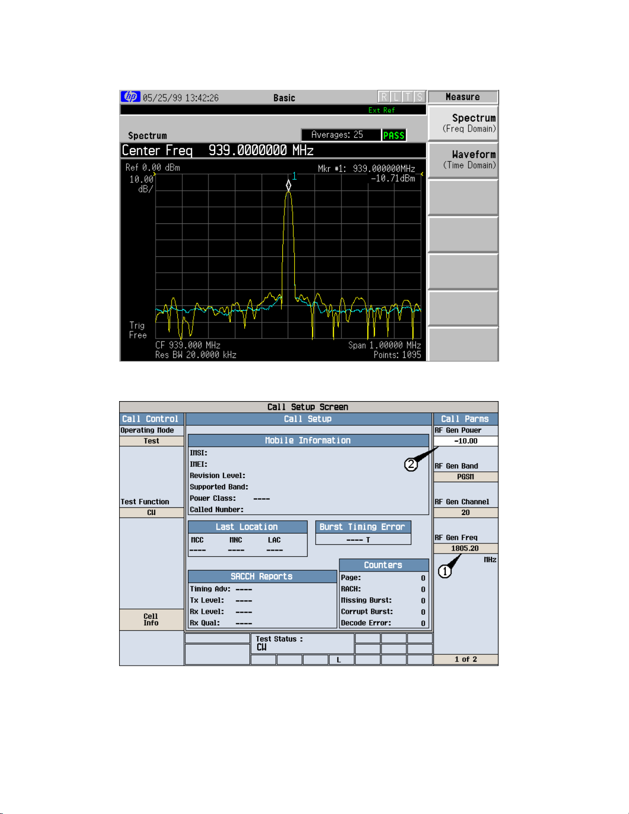
On the 8960 perform the following set up functions:
1. Press the blue ‘SHIFT’ button and the ‘PRESET’ button (front
panel buttons not shown above).
2. Press the display ‘Operating Mode’ button and set mode to
Test using the knob.
3. Press the display ‘Test Function’ button and set function to
CW using the knob.
4. Press the ‘RF Gen Freq’ button and set frequency to 939 MHz
using the number keypad and the knob.
5. Press the ‘ RF Gen Power’ button and set power to -10 dBm
using the number keypad and the knob.
4

8960 Operational Verification
Analog Generator Level Accuracy, cont.
Manual
Verification
On the E4406A, press the ‘Preset’ System button, the ‘MODE’ Control
button and set to ‘Basic’ Mode .
On the E4406A, press the ‘FREQUENCY’ Control button and set the
Center Frequency to 939 MHz.
5

8960 Operational Verification
Analog Generator Level Accuracy, cont.
Manual
Verification
On the E4406A, press the ‘ZOOM’ button, the ‘Marker’ button, and the ‘Search’
button. Select the ‘TRACE’ screen button and set the trace to Spectrum
Average.
On the E4406A, press the ‘MEASURE’ Control button.
6
8960 Operational Verification
Analog Generator Level Accuracy, cont.
Manual
Verification
Step the 8960 down in amplitude in 10 dB increments to -80 dBm.
Insure that each level step is accurate within ± 2 dB.
On the 8960 perform the following set up functions:
1. Press the ‘RF Gen Freq’ button and set frequency to 1805.2
MHz.
2. Press the ‘ RF Gen Power’ button and set power to -10 dBm.
7

8960 Operational Verification
Analog Generator Level Accuracy, cont.
Manual
Verification
On the E4406A set Center Frequency to 1.8052 GHz. Step the 8960 down in
amplitude in 10 dB increments to -80 dBm. Insure that each level step is
accurate within ± 2 dB.
On the 8960 perform the following set up functions:
1. Press the ‘RF Gen Freq’ button and set frequency to 1930.2 MHz.
2. Press the ‘ RF Gen Power’ button and set power to -10 dBm.
8

8960 Operational Verification
Analog Generator Level Accuracy, cont.
Manual
Verification
On the E4406Aset Center Frequency to 1.9302 GHz. Step the 8960
down in amplitude in 10 dB increments to -80 dBm. Insure that each
level step is accurate within ± 2 dB.
Important Note:
The 8960 contains 2 complete signal generator sources (these are very
similar to the E4432/33B Signal Generator).
The operating firmware of the 8960 only provides for operation of 1
source using the manual user interface (front panel) in the analog mode.
It is not possible to test the second source in a analog mode using any
manual method.
However….the second source can be tested manually in a GSM
transmit mode. See the test titled “GSM Generator Amplitude Flatness.
Peak Phase Error, RMS Phase Error, and Frequency Error --- Source 2”
in this section.
Testing source 2 in an analog mode requires using the Verification
Automated Software.
9

8960 Operational Verification
Analog Generator Spectral Purity
Manual
Verification
Analog Generator Spectral Purity is a test to insure that the 8960 has harmonics and
spurious signals within specification.The test is run by setting the 8960 to a carrier
frequency of 300 MHz and power level of -10 dBm. Harmonics and spurious are
checked at 450MHz, 600 MHz, 750 MHz, and 900 MHz. The expected limits are:
Spectral Purity Harmonics - ≤ -25 dBc
Sub-Harmonics - ≤ -40 dBc
Non-Harmonics - ≤ -55 dBc <1500 kHz
≤ -68 dBc >1500 kHz
The current operating firmware in the 8960 does not allow manual operation of
amplitude or frequency using incremental steps for either Signal Generator 1 or 2, a PC
with controlling software is required.
Connect the 8960 RF In/Out Connector to the E4406A RF Input.
On the 8960 perform the following set up functions:
1. Press the blue ‘SHIFT’ button and the ‘PRESET’ button (front panel buttons not
shown above).
2. Press the display ‘Operating Mode’ button and set mode to Test using the
knob. 3. Press the display ‘Test Function’ button and set function to CW using
the knob. 4. Press the ‘RF Gen Freq’ button and set frequency to 300 MHz
using the number keypad and the knob.
5. Press the ‘ RF Gen Power’ button and set power to -10 dBm using the number
keypad and the knob.
10
8960 Operational Verification
Analog Generator Spectral Purity
Manual
Verification
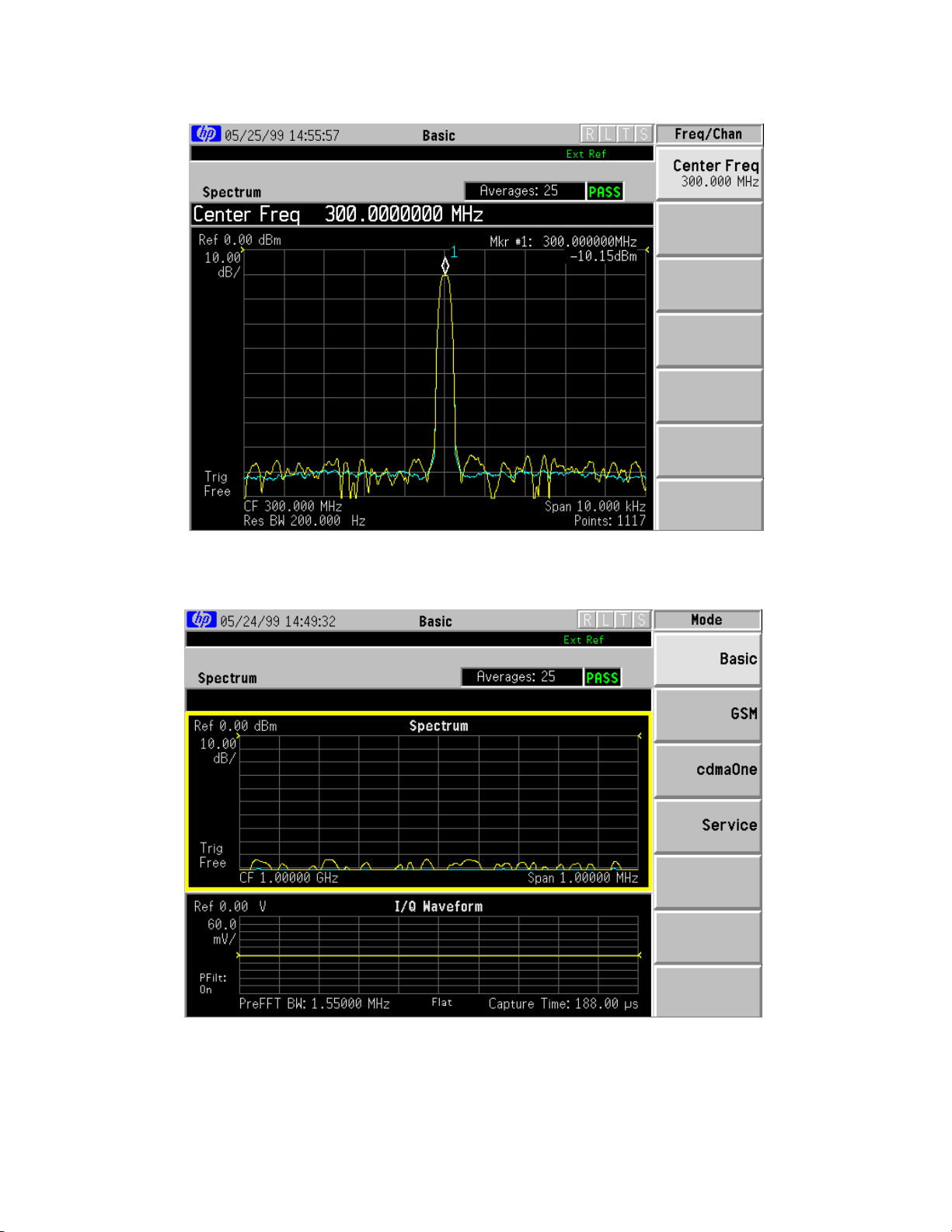
On the E4406A, press the ‘Preset’ System button, press the ‘Mode’ Control
button and set to ‘Basic’ Mode.
ON the E4406A make the following settings: Center Freq: 300 MHz Span: 10
kHz
Press the ‘ZOOM’ button, the ‘Marker’ button, and the ‘Search’ button. Select
the ‘TRACE’ screen button and set the trace to Spectrum Average. The 8960
amplitude should equal -10 dBm ± 2 dB.
11
8960 Operational Verification
Analog Generator Spectral Purity
Manual
Verification
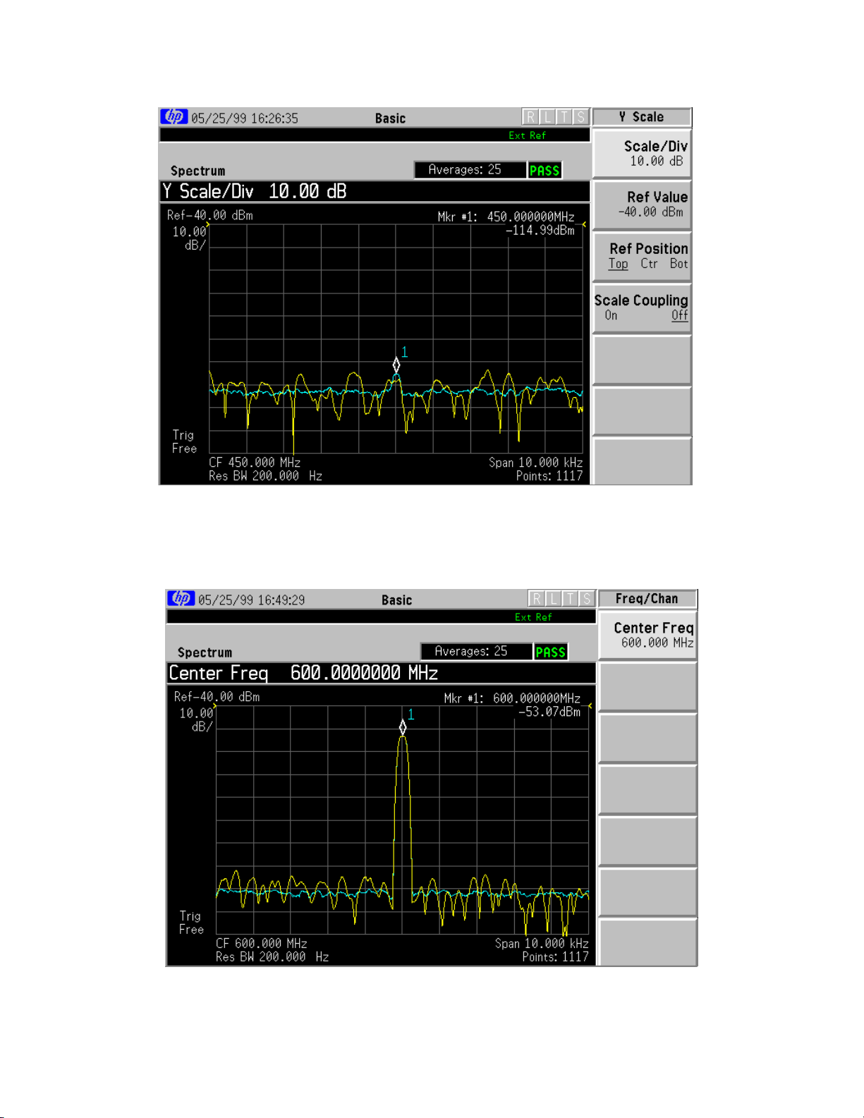
On the E4406A set the center frequency to 450 MHz. Press the
‘AMPLITUDE’ button and set Ref Value to -50 dBm. The Sub-Harmonic
expected limit is: ≤ -50 dBm.
On the E4406A set Center Frequency to 600 MHz. The Harmonic expected
limit is: ≤ -35 dBm
12
8960 Operational Verification
Analog Generator Spectral Purity
Manual
Verification
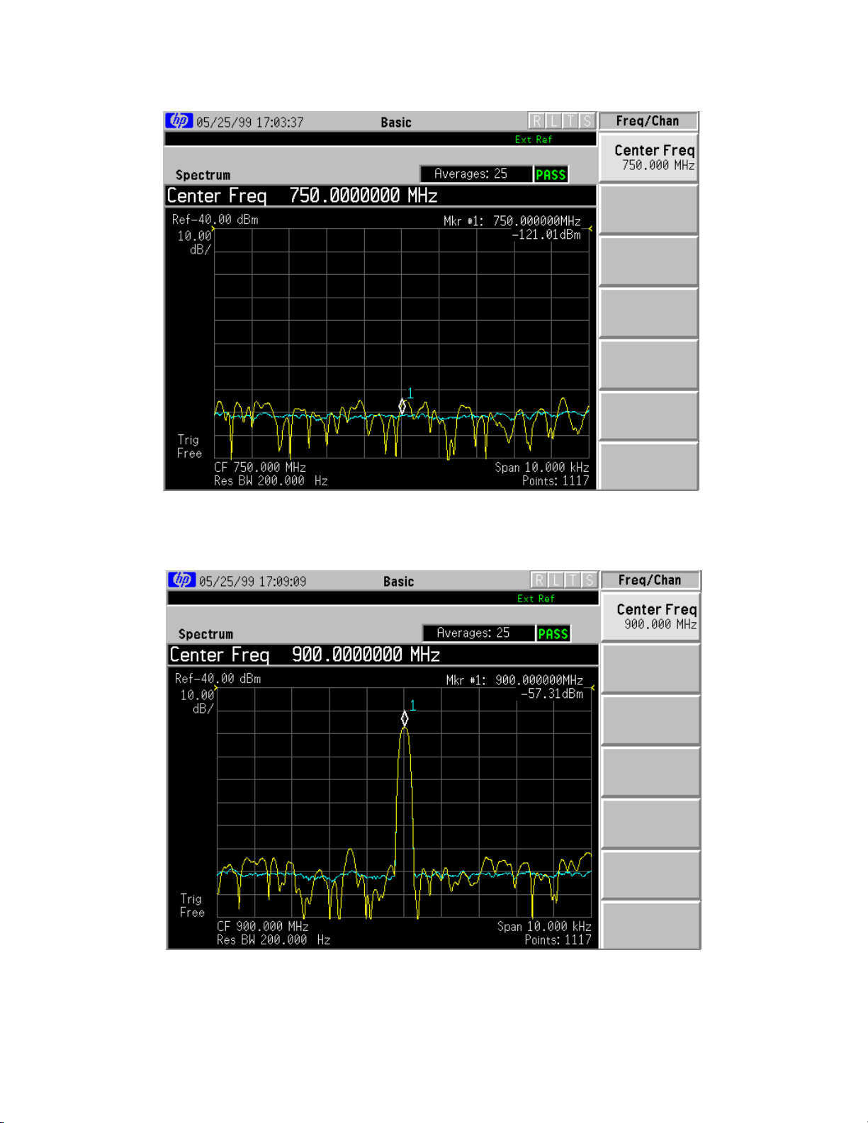
On the E4406A set the Center Frequency to 750 MHz. The Sub-Harmonic
expected limit is: ≤ -50 dBm
On the E4406A set the Center Frequency to 900 MHz. The Harmonic
expected limit is: ≤ -35 dBm .
13
 Loading...