


Service Guide
Agilent Technologies
89410A Vector Signal Analyzer
Part Number: 89410-90103
Supersedes: 89410-90065
Printed in USA
March 2002
© Copyright 2001-2002 Agilent Technologies Inc.

The information contained in this document is subject to change without
notice.
Agilent Technologies makes no warranty of any kind with regard to this
material, including but not limited to, the implied warranties of
merchantability and fitness for a particular purpose. Agilent
Technologies shall not be liable for errors contained herein or for
incidental or consequential damages in connection with the furnishing,
performance, or use of this material.
Safety Information
The following safety notes are used throughout this manual. Familiarize
yourself with each of the notes and it’s meaning before operating this
instrument.
WARNING: Warning denot es a hazard. It calls attention to a procedure
which, if not correctly performed or adhere d to, could re sul t in injury or loss of lif e.
Do not proceed beyond a warning note until the indicated conditions are fully
understood and met.
CAUTION: Caution denotes a hazard. It calls attention to a procedure that, if not
correctly performed or adhered to, could result in damage to or destruction of the
instrument. Do not proceed beyond a caution sign until the indicated conditions are
fully understood and met.
WARNING: This is a Safety Class 1 Product (provided with a protective
earthing ground incorporated in the power cord). The mains plug shall only be
inserted in a socket out let provid ed with a protected earth contact. Any
interruption of the pro te ctive conductor inside or outside of the product is likely to
make the product dangerous. Intentional interruption is prohibited.
ii

WARNING: These servicing instructions are for use by qualified personnel
only. To avoid electrical shock, do not perform any servicing unless you are
qualified to do so.
WARNING: The power cord is connected to internal capacitors that may
remain live for 5 seconds after disconnecting the plug from it’s power supply.
Warranty
This Agilent Technologies instrument product is warranted against
defects in material and workmanship for a period of three years from
date of shipment. During the warranty period, Agilent Technologies will,
at its option, either repair or replace products which prove to be
defective.
For warranty service or repair, this product must be returned to a service
facility designated by Agilent Technologies. Buyer shall prepay shipping
charges to Agilent Technologies and Agilent Technologies shall pay
shipping charges to return the product to Buyer. However, Buyer shall
pay all shipping charges, duties, and taxes for products returned to
Agilent Technologies from another country.
Agilent Technologies warrants that its software and firmware designated
by Agilent Technologies for use with an instrument will execute its
programming instructions when properly installed on that instrument.
Agilent Technologies does not warrant that the operation of the
instrument, or software, or firmware will be uninterrupted or error-free.
iii

LIMITATION OF WARRANTY
The foregoing warranty shall not apply to defects resulting from improper
or inadequate maintenance by Buyer, Buyer-supplied software or
interfacing, unauthorized modification or misuse, operation outside of
the environmental specifications for the product, or improper site
preparation or maintenance.
NO OTHER WARRANTY IS EXPRESSED OR IMPLIED. AGILENT
TECHNOLOGIES SPECIFICALLY DISCLAIMS THE IMPLIED
WARRANTIES OF MERCHANTABILITY AND FITNESS FOR A
PARTICULAR PURPOSE.
EXCLUSIVE REMEDIES
THE REMEDIES PROVIDED HEREIN ARE BUYER’S SOLE AND
EXCLUSIVE REMEDIES. AGILENT TECHNOLOGIES SHALL NOT BE
LIABLE FOR ANY DIRECT, INDIRECT, SPECIAL, INCIDENTAL, OR
CONSEQUENTIAL DAMAGES, WHETHER BASED ON CONTRACT, TORT,
OR ANY OTHER LEGAL THEORY.
iv

In this manual…
Chapter 1 Troubleshooting the Analyzer
Chapter 2 Adjusting the Analyzer
Chapter 3 Replacing Assemblies
Chapter 4 Replaceable Parts
Chapter 5 Circuit Descriptions
● Provides step-by-step instructions for isolating most failures to the
faulty assembly
● Provides step-by-step instructions for adjusting the analyzer
● Provides step-by-step instructions to follow before and after replacing
an assembly. This chapter also provides step-by-step instructions for
disassembling the analyzer
● Provides ordering information and lists the replaceable parts
● Provides the overall instrument description and individual assembly
description
Chapter 6 Voltages and Signals
● Shows where the signals and voltages are used in the analyzer and
describes each signal
Chapter 7 Internal Test Descriptions
● Describes the power-on test, calibration routine, fault log messages,
and self tests
Chapter 8 Backdating
● Provides information necessary to modify this manual for
instruments that differ from those currently being produced
Chapter 9 Quick Reference
● Provides all the block diagrams and the “A90/A91 Motherboard
Voltages” table
v

Notation Conventions
Before you use this book, it is important to understand the types of keys on
the front panel of the analyzer and how they are denoted in this book.
Hardkeys
● Hardkeys are front-panel buttons whose functions are always the
same. Hardkeys have a label printed directly on the key. In this book,
they are printed like this: [
Softkeys
● Softkeys are keys whose functions change with the analyzer’s current
menu selection. A softkey’s function is indicated by a video label to
the left of the key (at the edge of the analyzer’s screen). In this book,
softkeys are printed like this: [
Toggle Softkeys
● Some softkeys toggle through multiple settings for a parameter.
Toggle softkeys have a word highlighted (of a different color) in their
label. Repeated presses of a toggle softkey changes which word is
highlighted with each press of the softkey. In this book, toggle softkey
presses are shown with the requested toggle state in bold type as
follows:
“Press [
selection on is active.”
Hardkey].
softkey].
key nameon]” means “press the softkey [key name] until the
Shift Functions
● In addition to their normal labels, keys with blue lettering also have a
shift function. This is similar to shift keys on a pocket calculator or
the shift function on a typewriter or computer keyboard. Using a
shift function is a two-step process. First, press the blue [
(at this point, the message “shift” appears on the display). Then press
the key with the shift function you want to enable. Shift function are
printed as two key presses, like this:
Shift] [Shift Function]
[
vi
Shift] key

Numeric Entries
● Numeric values may be entered by using the numeric keys in the
lower right hand ENTRY area of the analyzer front panel. In this
book, values which are to be entered from these keys are indicted
only as numerals in the text, like this:
Press 50, [
enter]
Ghosted Softkeys
● A softkey label may be shown in the menu when it is inactive. This
occurs when a softkey function is not appropriate for a particular
measurement or not available with the current analyzer
configuration. To show that a softkey function is not available, the
analyzer ‘’ghosts’’ the inactive softkey label. A ghosted softkey
appears less bright than a normal softkey. Settings/values may be
changed while they are inactive. If this occurs, the new settings are
effective when the configuration changes such that the softkey
function becomes active.
vii
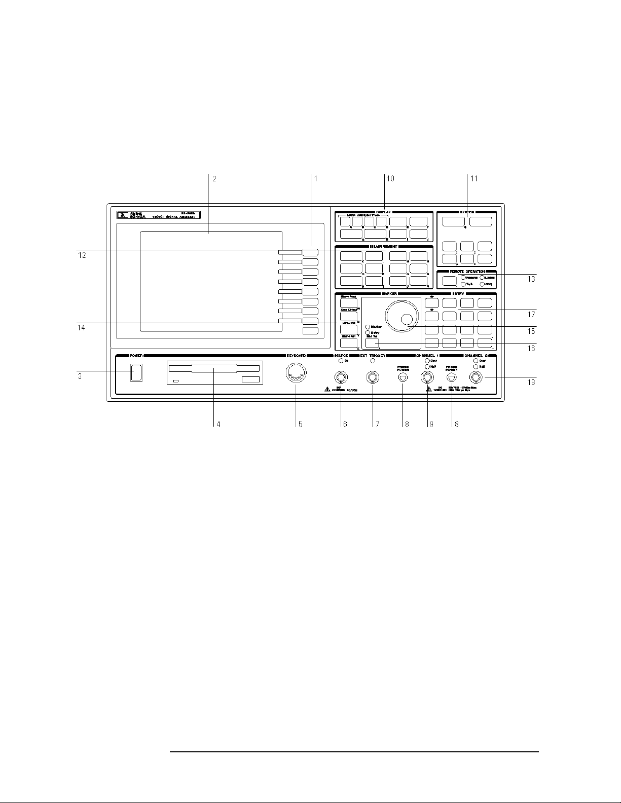
The Agilent 89410A at a Glance
viii

Agilent 89410A Front Panel
1-A softkey’s function changes as different menus are displayed. Its
current function is determined by the video label to its left, on the
analyzer’s screen.
2-The analyzer’s screen is divided into two main areas. The menu area, a
narrow column at the screen’s right edge, displays softkey labels. The
data area, the remaining portion of the screen, displays traces and other
data.
3-The POWER switch turns the analyzer on and off.
4-Use a 3.5-inch flexible disk (DS,HD) in this disk drive to save your work.
5-The KEYBOARD connector allows you to attach an optional keyboard to
the analyzer. The keyboard is most useful for writing and editing
Instrument BASIC programs.
6- The SOURCE connector routes the analyzer’s source output to your
DUT. Output impedance is selectable: 50 ohms or 75 ohms.
7-The EXT TRIGGER connector lets you provide an external trigger for
the analyzer.
8-The PROBE POWER connectors provide power for
various Agilent active probes.
9-The CHANNEL 1 input connector routes your test signal or DUT output
to the analyzer’s receiver. Input impedance is selectable: 50 ohms, 75
ohms, or 1 megohm.
10-Use the DISPLAY hardkeys and their menus to select and manipulate
trace data and to select display options for that data.
11-Use the SYSTEM hardkeys and their menus to control various system
functions (online help, plotting, presetting, and so on).
12-Use the MEASUREMENT hardkeys and their menus to control the
analyzer’s receiver and source, and to specify other measurement
parameters.
13-The REMOTE OPERATION hardkey and LED indicators allow you to
set up and monitor the activity of remote devices.
14-Use the MARKER hardkeys and their menus to control marker
positioning and marker functions.
15-The knob’s primary purpose is to move a marker along the trace. But
you can also use it to change values during numeric entry, move a cursor
during text entry, or select a hypertext link in help topics.
ix

16-Use the Marker/Entry key to determine the knob’s function. With the
Marker indicator illuminated, the knob moves a marker along the trace.
With the Entry indicator illuminated, the knob changes numeric entry
values.
17-Use the ENTRY hardkeys to change the value of numeric parameters
or to enter numeric characters in text strings.
18-The optional CHANNEL 2 input connector routes your test signal or
DUT output to the analyzer’s receiver. Input impedance is selectable: 50
ohms, 75 ohms, or 1 megohm. For easy of upgrading, the CHANNEL 2
BNC connector is installed even if option AY7 (second input channel) is
not installed.
For more details on the Agilent 89410A front panel, display the online help
topic ‘’Front Panel.’’
Before applying power
Verify that the product is set to match the available line voltage, the
correct fuse is installed, and all safety precautions are taken. Note the
instrument’s external markings described in “Safety symbols and
instrument markings” on page x.
Ground the instrument
To minimize shock hazard, the instrument chassis and cover must be
connected to an electrical protective earth ground. The instrument must
be connected to the ac power mains through a grounded power cable,
with the ground wire firmly connected to an electrical ground (safety
ground) at the power outlet. Any interruption of the protective
(grounding) conductor or disconnection of the protective earth terminal
will cause a potential shock hazard that could result in personal injury.
Fuses
Use only fuses with the required rated current, voltage, and specified
type (normal blow, time delay). Do not use repaired fuses or
short-circuited fuse holders. To do so could cause a shock or fire hazard.
Safety symbols and instrument markings
Symbols and markings in manuals and on instruments alert you to
potential risks, provide information about conditions, and comply with
international regulations. Table 1 defines the symbols and markings you
may find in a manual or on an instrument.
x
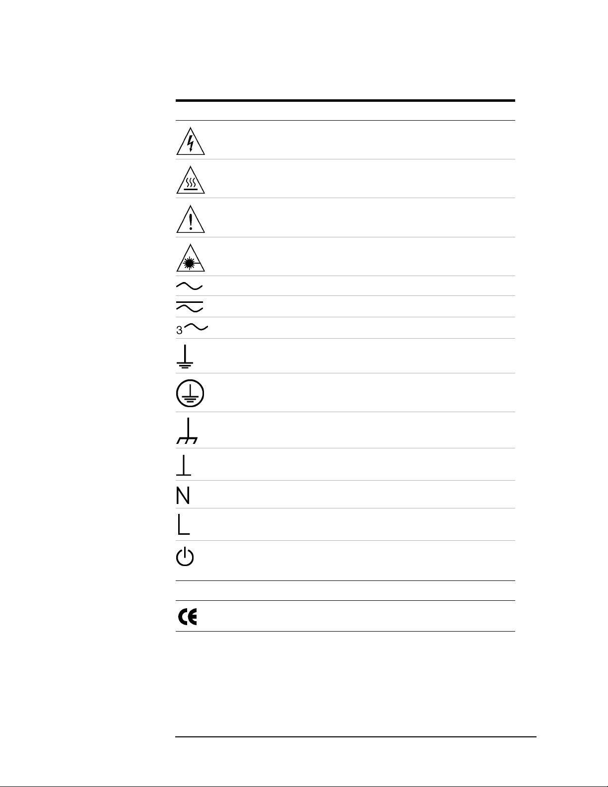
Table 1 Safety symbols and instrument markings
Safety symbols
Warning: risk of electric shock.
Warning: ho t surface
Caution: refer to accompanying documents.
Laser radiat io n sym b ol : m arked on products that have a laser o ut put.
Alternating current.
Both direct and alternating current.
Three-phase alternating current.
Earth (ground) terminal
Protective earth (ground) terminal
Frame or chassis terminal
Terminal is at earth potential. Used for measurement and control circuits designed to
be operated with one terminal at earth potential.
Terminal for neutral conductor on permanently installed equipment.
Terminal for line conductor on permanently installed equipment.
Standby (supply); units with this symbol are not completely disconnected from ac
mains when this switch is off. To completely disconnect the unit from ac mains, either
disconnect the power cord, or have a qualified electrician install an external switch.
Instrument markings
The CE mark is a registered trademark of the European Community. If it is
accompanied by a year, it indicates the year the design was proven.
xi
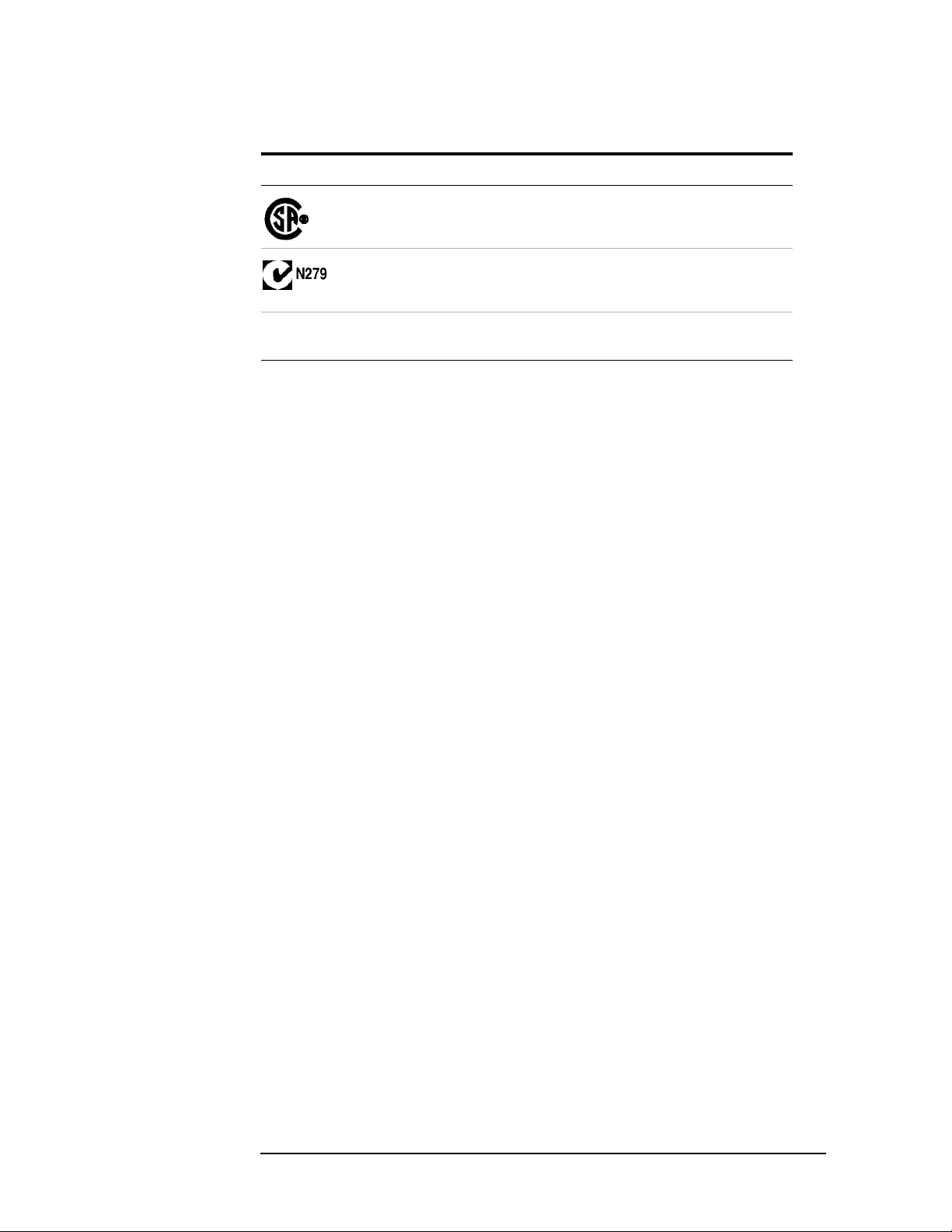
Table 1 Safety symbols and instrument markings (continued)
Safety symbols
The CSA mark is a registered trademark of the Canadian Standards Association.
The C-tick mark is a registered trademark of the Spectrum Management Agency of
Australia. This signifies compliance with the Australian EMC Framework regulations
under the terms of the Radio Communications Act of 1992.
1SM1-A
This text indicates that the instrument is an Industrial Scientific and Medical Group 1
Class A product (CISPER 11, Clause 4).
xii

Service and Support
Any adjustment, maintenance, or repair of this product must be
performed by qualified personnel. Contact your customer engineer
through your local Agilent Technologies Service Center. You can find a
list of local service representatives on the Web at:
http://www.agilent.com/ services/English/index.html
If you do not have access to the Internet, one of these centers can direct
you to your nearest representative.
Table 2 Telephone numbers for Agilent Call Centers
United States: Test and Measurement Call Center
Canada: (905) 206 4725
Europe: (31 20) 547 9900
Japan: Measurement Assistance Center
(800) 452 4844 (toll-free in US)
(81) 426 56 7832
(81) 426 56 7840 (FAX)
Latin America: (305) 267 4245
(305) 267 4288 (FAX)
Australia/New Zealand: 1 800 629 485 (Australia)
0800 738 378 (New Zealand))
Asia-Pacific: (852) 2599 7777
(852) 2506 9285 (FAX)
xiii

xiv

Contents
1. Troubleshooting the Analyzer
How to troubleshoot the analyzer . . . . . . . . . . . . . . . . . . . . . . . . . . . . . . . . . . . . . . . . . . . . . . .1-8
To perform initial verification . . . . . . . . . . . . . . . . . . . . . . . . . . . . . . . . . . . . . . . . . . . . . . . . .1-10
To troubleshoot the power supply . . . . . . . . . . . . . . . . . . . . . . . . . . . . . . . . . . . . . . . . . . . . . .1-15
To troubleshoot display failures . . . . . . . . . . . . . . . . . . . . . . . . . . . . . . . . . . . . . . . . . . . . . . .1-25
To perform self tests. . . . . . . . . . . . . . . . . . . . . . . . . . . . . . . . . . . . . . . . . . . . . . . . . . . . . . . . .1-32
To troubleshoot self-test lockup failures . . . . . . . . . . . . . . . . . . . . . . . . . . . . . . . . . . . . . . . . .1-48
To troubleshoot intermittent failures . . . . . . . . . . . . . . . . . . . . . . . . . . . . . . . . . . . . . . . . . . .1-52
To troubleshoot performance test failures . . . . . . . . . . . . . . . . . . . . . . . . . . . . . . . . . . . . . . .1-58
To troubleshoot front-end control failures . . . . . . . . . . . . . . . . . . . . . . . . . . . . . . . . . . . . . . .1-60
To troubleshoot source and calibrator out failures. . . . . . . . . . . . . . . . . . . . . . . . . . . . . . . . .1-62
To troubleshoot input and ADC failures. . . . . . . . . . . . . . . . . . . . . . . . . . . . . . . . . . . . . . . . .1-71
To troubleshoot two channel analyzer failures. . . . . . . . . . . . . . . . . . . . . . . . . . . . . . . . . . . .1-75
To troubleshoot auto-range failures . . . . . . . . . . . . . . . . . . . . . . . . . . . . . . . . . . . . . . . . . . . .1-80
To troubleshoot trigger failures. . . . . . . . . . . . . . . . . . . . . . . . . . . . . . . . . . . . . . . . . . . . . . . .1-83
To troubleshoot disk drive failures . . . . . . . . . . . . . . . . . . . . . . . . . . . . . . . . . . . . . . . . . . . . .1-88
To troubleshoot serial port failures . . . . . . . . . . . . . . . . . . . . . . . . . . . . . . . . . . . . . . . . . . . . .1-91
To troubleshoot DIN connector failures . . . . . . . . . . . . . . . . . . . . . . . . . . . . . . . . . . . . . . . . .1-92
To troubleshoot memory battery failures . . . . . . . . . . . . . . . . . . . . . . . . . . . . . . . . . . . . . . . .1-93
To troubleshoot sync out and parallel port failures . . . . . . . . . . . . . . . . . . . . . . . . . . . . . . . .1-95
To troubleshoot system interconnect and LAN port failures. . . . . . . . . . . . . . . . . . . . . . . . .1-96
2. Adjusting the Analyzer
To adjust oven shutdown . . . . . . . . . . . . . . . . . . . . . . . . . . . . . . . . . . . . . . . . . . . . . . . . . . . . . .2-7
To adjust input flatness . . . . . . . . . . . . . . . . . . . . . . . . . . . . . . . . . . . . . . . . . . . . . . . . . . . . . .2-10
To adjust input capacitance. . . . . . . . . . . . . . . . . . . . . . . . . . . . . . . . . . . . . . . . . . . . . . . . . . .2-13
To adjust input offset . . . . . . . . . . . . . . . . . . . . . . . . . . . . . . . . . . . . . . . . . . . . . . . . . . . . . . . .2-16
To adjust anti-alias filter . . . . . . . . . . . . . . . . . . . . . . . . . . . . . . . . . . . . . . . . . . . . . . . . . . . . .2-18
To adjust ADC. . . . . . . . . . . . . . . . . . . . . . . . . . . . . . . . . . . . . . . . . . . . . . . . . . . . . . . . . . . . . .2-24
To adjust 10 MHz low pass filter. . . . . . . . . . . . . . . . . . . . . . . . . . . . . . . . . . . . . . . . . . . . . . .2-25
To adjust auto-range detect level. . . . . . . . . . . . . . . . . . . . . . . . . . . . . . . . . . . . . . . . . . . . . . .2-29
To adjust reference oscillator. . . . . . . . . . . . . . . . . . . . . . . . . . . . . . . . . . . . . . . . . . . . . . . . . .2-32
To adjust oven frequency . . . . . . . . . . . . . . . . . . . . . . . . . . . . . . . . . . . . . . . . . . . . . . . . . . . . .2-34
To adjust calibrator . . . . . . . . . . . . . . . . . . . . . . . . . . . . . . . . . . . . . . . . . . . . . . . . . . . . . . . . .2-37
3. Replacing Assemblies
What to do before replacing the analog source. . . . . . . . . . . . . . . . . . . . . . . . . . . . . . . . . . . . .3-4
What to do after replacing an assembly . . . . . . . . . . . . . . . . . . . . . . . . . . . . . . . . . . . . . . . . . .3-5
To remove CPU and memory. . . . . . . . . . . . . . . . . . . . . . . . . . . . . . . . . . . . . . . . . . . . . . . . . . .3-8
To remove front panel . . . . . . . . . . . . . . . . . . . . . . . . . . . . . . . . . . . . . . . . . . . . . . . . . . . . . . .3-10
To remove the Flat Panel Display . . . . . . . . . . . . . . . . . . . . . . . . . . . . . . . . . . . . . . . . . . . . . .3-11
To place the A82 in the test position . . . . . . . . . . . . . . . . . . . . . . . . . . . . . . . . . . . . . . . . . . . .3-12
To remove disk drive . . . . . . . . . . . . . . . . . . . . . . . . . . . . . . . . . . . . . . . . . . . . . . . . . . . . . . . .3-14
To remove main power supply . . . . . . . . . . . . . . . . . . . . . . . . . . . . . . . . . . . . . . . . . . . . . . . .3-16
To remove analog motherboard. . . . . . . . . . . . . . . . . . . . . . . . . . . . . . . . . . . . . . . . . . . . . . . .3-18
To remove rear panel . . . . . . . . . . . . . . . . . . . . . . . . . . . . . . . . . . . . . . . . . . . . . . . . . . . . . . . .3-20
To remove digital motherboard . . . . . . . . . . . . . . . . . . . . . . . . . . . . . . . . . . . . . . . . . . . . . . . .3-23
A100 Display, Backlights, and Filter. . . . . . . . . . . . . . . . . . . . . . . . . . . . . . . . . . . . . . . . . . . .3-26
xv

Contents
4. Replaceable Parts
Ordering Information . . . . . . . . . . . . . . . . . . . . . . . . . . . . . . . . . . . . . . . . . . . . . . . . . . . . . . . . 4-4
Assemblies . . . . . . . . . . . . . . . . . . . . . . . . . . . . . . . . . . . . . . . . . . . . . . . . . . . . . . . . . . . . . . . . . 4-7
Cables. . . . . . . . . . . . . . . . . . . . . . . . . . . . . . . . . . . . . . . . . . . . . . . . . . . . . . . . . . . . . . . . . . . . 4-10
Instrument Covers and Handles. . . . . . . . . . . . . . . . . . . . . . . . . . . . . . . . . . . . . . . . . . . . . . . 4-12
Front Panel Parts . . . . . . . . . . . . . . . . . . . . . . . . . . . . . . . . . . . . . . . . . . . . . . . . . . . . . . . . . . 4-14
Rear Panel Parts . . . . . . . . . . . . . . . . . . . . . . . . . . . . . . . . . . . . . . . . . . . . . . . . . . . . . . . . . . . 4-16
Chassis Parts . . . . . . . . . . . . . . . . . . . . . . . . . . . . . . . . . . . . . . . . . . . . . . . . . . . . . . . . . . . . . . 4-18
Card Nest Parts. . . . . . . . . . . . . . . . . . . . . . . . . . . . . . . . . . . . . . . . . . . . . . . . . . . . . . . . . . . . 4-20
Screws, Washers, and Nuts. . . . . . . . . . . . . . . . . . . . . . . . . . . . . . . . . . . . . . . . . . . . . . . . . . . 4-21
Miscellaneous Parts. . . . . . . . . . . . . . . . . . . . . . . . . . . . . . . . . . . . . . . . . . . . . . . . . . . . . . . . . 4-22
5. Circuit Descriptions
Overall Instrument Description . . . . . . . . . . . . . . . . . . . . . . . . . . . . . . . . . . . . . . . . . . . . . . . . 5-4
A10 Analog Input. . . . . . . . . . . . . . . . . . . . . . . . . . . . . . . . . . . . . . . . . . . . . . . . . . . . . . . . . . . 5-15
A11 Front Panel Connector. . . . . . . . . . . . . . . . . . . . . . . . . . . . . . . . . . . . . . . . . . . . . . . . . . . 5-17
A12 Rear Panel Connector . . . . . . . . . . . . . . . . . . . . . . . . . . . . . . . . . . . . . . . . . . . . . . . . . . . 5-18
A21 A/D Converter . . . . . . . . . . . . . . . . . . . . . . . . . . . . . . . . . . . . . . . . . . . . . . . . . . . . . . . . . 5-19
A30 Digital Source. . . . . . . . . . . . . . . . . . . . . . . . . . . . . . . . . . . . . . . . . . . . . . . . . . . . . . . . . . 5-21
A35 Analog Source. . . . . . . . . . . . . . . . . . . . . . . . . . . . . . . . . . . . . . . . . . . . . . . . . . . . . . . . . . 5-24
A36 Trigger . . . . . . . . . . . . . . . . . . . . . . . . . . . . . . . . . . . . . . . . . . . . . . . . . . . . . . . . . . . . . . . 5-26
A40 CPU. . . . . . . . . . . . . . . . . . . . . . . . . . . . . . . . . . . . . . . . . . . . . . . . . . . . . . . . . . . . . . . . . . 5-28
A42 Memory. . . . . . . . . . . . . . . . . . . . . . . . . . . . . . . . . . . . . . . . . . . . . . . . . . . . . . . . . . . . . . . 5-31
A43 Expanded Memory . . . . . . . . . . . . . . . . . . . . . . . . . . . . . . . . . . . . . . . . . . . . . . . . . . . . . . 5-35
A47 DSP/Display Controller . . . . . . . . . . . . . . . . . . . . . . . . . . . . . . . . . . . . . . . . . . . . . . . . . . 5-37
A50 Digital Filter. . . . . . . . . . . . . . . . . . . . . . . . . . . . . . . . . . . . . . . . . . . . . . . . . . . . . . . . . . . 5-39
A55 Sample RAM/A56 Expanded Sample RAM . . . . . . . . . . . . . . . . . . . . . . . . . . . . . . . . . . 5-41
A60 Frequency Reference . . . . . . . . . . . . . . . . . . . . . . . . . . . . . . . . . . . . . . . . . . . . . . . . . . . . 5-44
A61 Clock . . . . . . . . . . . . . . . . . . . . . . . . . . . . . . . . . . . . . . . . . . . . . . . . . . . . . . . . . . . . . . . . . 5-46
A71 Pass Through . . . . . . . . . . . . . . . . . . . . . . . . . . . . . . . . . . . . . . . . . . . . . . . . . . . . . . . . . . 5-48
A81 Keyboard. . . . . . . . . . . . . . . . . . . . . . . . . . . . . . . . . . . . . . . . . . . . . . . . . . . . . . . . . . . . . . 5-50
A82 LCD Interface Circuit Descriptions . . . . . . . . . . . . . . . . . . . . . . . . . . . . . . . . . . . . . . . . 5-52
A85 Oven . . . . . . . . . . . . . . . . . . . . . . . . . . . . . . . . . . . . . . . . . . . . . . . . . . . . . . . . . . . . . . . . . 5-54
A90 Digital Motherboard . . . . . . . . . . . . . . . . . . . . . . . . . . . . . . . . . . . . . . . . . . . . . . . . . . . . 5-55
A91 Analog Motherboard . . . . . . . . . . . . . . . . . . . . . . . . . . . . . . . . . . . . . . . . . . . . . . . . . . . . 5-56
A92 Probe Power . . . . . . . . . . . . . . . . . . . . . . . . . . . . . . . . . . . . . . . . . . . . . . . . . . . . . . . . . . . 5-57
A95 Main Power Supply . . . . . . . . . . . . . . . . . . . . . . . . . . . . . . . . . . . . . . . . . . . . . . . . . . . . . 5-58
A96 Primary Power Supply. . . . . . . . . . . . . . . . . . . . . . . . . . . . . . . . . . . . . . . . . . . . . . . . . . . 5-61
A100 Display . . . . . . . . . . . . . . . . . . . . . . . . . . . . . . . . . . . . . . . . . . . . . . . . . . . . . . . . . . . . . . 5-63
A101 Disk Drive. . . . . . . . . . . . . . . . . . . . . . . . . . . . . . . . . . . . . . . . . . . . . . . . . . . . . . . . . . . . 5-64
A102 Fan . . . . . . . . . . . . . . . . . . . . . . . . . . . . . . . . . . . . . . . . . . . . . . . . . . . . . . . . . . . . . . . . . 5-65
6. Voltages and Signals
Assembly Locations and Connections. . . . . . . . . . . . . . . . . . . . . . . . . . . . . . . . . . . . . . . . . . . . 6-4
Power Supply Voltage Distribution . . . . . . . . . . . . . . . . . . . . . . . . . . . . . . . . . . . . . . . . . . . . . 6-7
RF Cables. . . . . . . . . . . . . . . . . . . . . . . . . . . . . . . . . . . . . . . . . . . . . . . . . . . . . . . . . . . . . . . . . . 6-8
A42 Memory. . . . . . . . . . . . . . . . . . . . . . . . . . . . . . . . . . . . . . . . . . . . . . . . . . . . . . . . . . . . . . . 6-10
A81 Keyboard. . . . . . . . . . . . . . . . . . . . . . . . . . . . . . . . . . . . . . . . . . . . . . . . . . . . . . . . . . . . . . 6-14
xvi

Contents
A90 and A91 Motherboards. . . . . . . . . . . . . . . . . . . . . . . . . . . . . . . . . . . . . . . . . . . . . . . . . . .6-16
A101 Disk Drive . . . . . . . . . . . . . . . . . . . . . . . . . . . . . . . . . . . . . . . . . . . . . . . . . . . . . . . . . . . .6-33
Interface Connectors . . . . . . . . . . . . . . . . . . . . . . . . . . . . . . . . . . . . . . . . . . . . . . . . . . . . . . . .6-35
7. Internal Test Descriptions
Power-on Test Descriptions . . . . . . . . . . . . . . . . . . . . . . . . . . . . . . . . . . . . . . . . . . . . . . . . . . . .7-4
Calibration Routine . . . . . . . . . . . . . . . . . . . . . . . . . . . . . . . . . . . . . . . . . . . . . . . . . . . . . . . . . .7-5
Fault Log Messages . . . . . . . . . . . . . . . . . . . . . . . . . . . . . . . . . . . . . . . . . . . . . . . . . . . . . . . . . .7-9
Self-Test Descriptions . . . . . . . . . . . . . . . . . . . . . . . . . . . . . . . . . . . . . . . . . . . . . . . . . . . . . . .7-13
Individual Self-Test Descriptions . . . . . . . . . . . . . . . . . . . . . . . . . . . . . . . . . . . . . . . . . . . . . .7-16
Self-Test Menu Map and HPIB Commands . . . . . . . . . . . . . . . . . . . . . . . . . . . . . . . . . . . . . .7-22
8. Backdating
To adjust clock . . . . . . . . . . . . . . . . . . . . . . . . . . . . . . . . . . . . . . . . . . . . . . . . . . . . . . . . . . . . . .8-5
To adjust display. . . . . . . . . . . . . . . . . . . . . . . . . . . . . . . . . . . . . . . . . . . . . . . . . . . . . . . . . . . . .8-7
To remove display. . . . . . . . . . . . . . . . . . . . . . . . . . . . . . . . . . . . . . . . . . . . . . . . . . . . . . . . . . . .8-9
Assemblies . . . . . . . . . . . . . . . . . . . . . . . . . . . . . . . . . . . . . . . . . . . . . . . . . . . . . . . . . . . . . . . .8-11
Cables . . . . . . . . . . . . . . . . . . . . . . . . . . . . . . . . . . . . . . . . . . . . . . . . . . . . . . . . . . . . . . . . . . . .8-13
Assembly Covers and Brackets . . . . . . . . . . . . . . . . . . . . . . . . . . . . . . . . . . . . . . . . . . . . . . . .8-14
Front Panel Parts. . . . . . . . . . . . . . . . . . . . . . . . . . . . . . . . . . . . . . . . . . . . . . . . . . . . . . . . . . .8-15
Overall Block Diagram. . . . . . . . . . . . . . . . . . . . . . . . . . . . . . . . . . . . . . . . . . . . . . . . . . . . . . .8-18
A45 DSP/Display Controller Block Diagram . . . . . . . . . . . . . . . . . . . . . . . . . . . . . . . . . . . . .8-20
A80 Keyboard Block Diagram . . . . . . . . . . . . . . . . . . . . . . . . . . . . . . . . . . . . . . . . . . . . . . . .8-21
Assembly Locations and Connections . . . . . . . . . . . . . . . . . . . . . . . . . . . . . . . . . . . . . . . . . . .8-22
9. Quick Reference
xvii

Contents
xviii

1 Troubleshooting the Analyzer

Troubleshooting the Analyzer
● How to troubleshoot the analyzer, page1-8
● To perform initial verificatio n, page 1-10
● To troubleshoot the power supply, page 1-15
● To troubleshoot display failures, page 1-25
● To perform self tests, page 1-32
● To troubleshoot self-test lockup failures, page1-48
● To troubleshoot intermittent failures, page 1-52
● To troubleshoot performance test failures, page 1-58
● To troubleshoot front-end control failures, page 1-60
● To troubleshoot source and calibrator out failures, page1-62
● To troubleshoot input and ADC failures, page 1-71
● To troubleshoot two channel analyzer failures, page1-75
● To troubleshoot auto-range failures, page1-80
● To troubleshoot trigger failures, page 1-83
● To troubleshoot disk drive failures, page1-88
● To troubleshoot serial port failures, page 1-91
● To troubleshoot DIN connector failures, page1-92
● To troubleshoot memory battery failures, page1-93
● To troubleshoot sync out and parallel port failures, page1-95
● To troubleshoot system interconnect and LAN port failures, page 1-96
1-2

Troubleshooting the Analyzer
This chapter contains troubleshooting tests that can isolate most failures
to the faulty assembly. The section ‘’How to troubleshoot the analyzer’’
tells you which test to start with based on the failure. The test you start
with will either isolate the faulty assembly or send you to another test to
continue troubleshooting.
Safety Considerations
The Agilent 89410A DC-10 MHz Vector Signal Analyzer is a Safety Class 1
instrument (provided with a protective earth terminal). Although the
instrument has been designed in accordance with international safety
standards, this manual contains information, cautions, and warnings
that must be followed to ensure safe operation and retain the instrument
in safe operating condition. Service must be performed by trained
service personnel who are aware of the hazards involved (such as fire
and electrical shock).
Troubleshooting the Analyzer
WARNING: Any interruption of the protecti ve (groundin g) conduct or inside or
outside the analyzer, or disconnection of the protective earth terminal can expose
operators to potentially dangerous voltages.
An operator should not remove any covers, screws, shields or in any other way
access the interior of the Agilent 89410A DC-10 MHz Vector Si gnal Analyzer unless
instructed by an option installation note. There are no operator controls inside the
analyzer.
Only fuses with the require d curre nt ratin g and of the specifi ed type sh ould be used
for replacement. The use of repaired fuses or s hort c ir cuit ing the fuse holder is not
permitted. Whenever it is likely that the protection offere d by the fuse has been
impaired, the analyzer must be made inoperative and secured against any
unintended operation.
When power is removed from the Agilent 89410A DC-10MHz Vector Signal
Analyzer, +11000volts are present in the CRT for approximately 3 seconds. Be
extremely careful wh en working in proximity to this area during this time. The
high voltage can cause serious personal injury if contacted.
1-3

Troubleshooting the Analyzer
CAUTION: Do not connect or disconnect ribbon cables with the power switch set
to on ( l ). Power transients caused by connecting or disconnecting a cable can
damage circuit assemblies.
Equipment Required
The following table lists the recommended equipment needed to adjust and
troubleshoot the analyzer. Other equipment may be substituted for the
recommended model if it meets or exceeds the listed critical specifications.
When substitutions are made, you may have to modify the procedures to
accommodate the different operating characteristics.
Recommended Test Equipment
Instrument Critical Spec ifications Recommende d Model
Frequency Standard Accuracy ±0.5 ppm Agilent 5061B
Frequency Synthesizer Frequency range 3 Hz to 10 MHz
Milliwatt Power Meter Range ±0.2 dBm
Spectrum Analyzer Frequency range 100 Hz to 40 MHz
Digital Multimeter Accuracy 25 ppm
Frequency Counter Frequency range 3 to 30 MHz
Network Analyzer Range 10 kHz to 60 MHz
Amplitude range −36 to +20 dBm
Amplitude resolution 0.01 Hz
Impedance 50 Ω
Harmonic distor tion <−30 dBc
Spurious <−70 dBc
External reference input
Accuracy ±0.0625 dB
Amplitude range −60 to +15 dBm
Dynamic range <−67 dBc
Tracking Source @ 0 dBm
Impedance 50 Ω and 75 Ω
External reference input
Maximum volts range ≥400 Vdc
Resolution <1 Hz
Frequency accuracy ±0.25 Hz
Impedance 1MΩ
Resolution 10 Hz
Input impedance 50 Ω
Amplitude
range −42dBm to +10 dBm
resolution 0.25 dB
dynamic acc u racy 0. 3 dBp-p from 10 kHz to 16 MHz
Agilent 3326A
Alternate
Agilent 3325A
Agilent 3325B
W&G EPM-1 †
Agilent 3585B
Alternate
Agilent 3585A
Agilent 3588A
Agilent 3589A
Agilent3458A
Alternate
Agilent 3456A
Agilent 5334B opt 010
Agilent3577B
Alternate
Agilent4195A
Agilent3589A with
Agilent35689A
†Wandel & Goltermann Inc., 1800 Wyatt Drive, Suite 2, Santa Clara, CA 95054 U.S.A (408)988-7622
1-4

Recommended Test Equipment (continued)
Logic Probe TTL/CMOS Agilent 545A
Oscilloscope Bandwidth ≥150MHz
Oscilloscope Probe Input R ≥1MΩ
Oscilloscope Probe Input R ≥1MΩ
50 Ω Feedthrough Termination
(2 for opt AY7)
(2) 50 Ω Termination ±2% at dc Pomona Model 3840-50 †
ThinLAN Transceiver AUI to ThinLAN adapter Agilent 28641B
Cables (4) 50 Ω BNC
Adapters BNC(f)-to-Dual Banana Plug
Service Kit
10 kW Series Re s is tor †† Value: 10 kΩ
CPU/Memory Service Utility
Disk
Troubleshooting the Analyzer
Alternate
Agilent5006A
Agilent5005A/B
Agilent54111D
Vertical sensitivity 10 mV/div
Input coupling AC, DC, 50Ω, 1MΩ
Trigger Ext, Int
Agilent10438A
Division Ratio 1:1
Agilent10431A
Division Ratio 10:1
Accuracy ±0.2% Agilent 11048C
Alternate
Agilent11048C with
Agilent1250-0774
Agilent 8120-1840
Test clips-to-double banana plug
N(m)-to-BNC(f) (2)
Test Clips-to-BNC(f)
BNC Tee
N(f)-to-BNC(f)
BNC(f)-to-Dual Banana Plug(m)
BNC(f)-to-BNC(f)
Includes
A10/A35 extender board
A36/A60 extender board
A61 extender board
Motherboard cable extraction tool
Plastic screw driver
Flat-edge adjustment tool
SMB extender cable (2)
BNC(m)-to-SMB(f) cable (2)
SMB(m)-to-SMB(m) adapter (2)
Accuracy: 1%
Power: 0.125 Ω
Agilent11002A
Agilent1251-2816
Agilent1250-0780
Pomona Model 2631 †
Agilent 1250-0781
Agilent 1250-1536
Agilent 1251-2277
Agilent 1250-0080
Agilent 89410-84401
Includes
Agilent 89410-B1001‡
Agilent 89410-B1002‡
Agilent 89410-B1008‡
Agilent 8710-2050
Agilent 8710-2056
Agilent 8710-1928
Agilent 03585-61601
Agilent 03585-61616
Agilent 1250-0669
Agilent 0757-0442
Agilent89410-19463
†ITT Pomona Electronics, 1500 East Ninth Street, Pomona, CA 91769 U.S.A. (714) 469-2900 FAX (714) 629-3317
‡Individual extender boards cannot be ordered. To order all three extender
Agilent 89410-66515.
††See the following for assembly.
boards in this kit, order
1-5
Troubleshooting the Analyzer
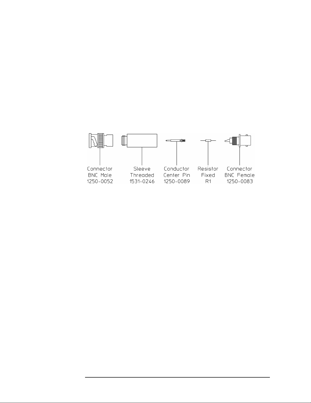
Suggested Assembly for Series Resistor
The following is a suggested assembly for the 10 kW series resistor. The
Ω series resistor is required for the Input Offset adjustment.
10 k
1 Cut resistor leads to 12 mm on each end.
2 Solder one resistor lead to the center conductor of the BNC female
connector.
3 Solder the conductor center pin to the other lead of the resistor.
4 Screw the sleeve and the BNC male connector into place. Tighten
securely.
Troubleshooting Hints
● Check that the analyzer has the latest firmware before starting the
troubleshooting procedures.
● Incorrect bias supply voltages can cause false diagnostic messages.
Most troubleshooting procedures do not check the power supply
voltages through the motherboard. If you suspect incorrect supply
voltages to an assembly, use the ‘’A90/A91 Motherboard Voltages’’
table on page 6-24 and an extender board to check the voltages at the
assembly.
● The troubleshooting procedures do not isolate failures to cables or
connectors. If you suspect a cable or connector failure, check the
device for continuity.
● Cables can cause intermittent hardware failures.
● Noise or spikes in the power supply can cause the analyzer to fail.
● Measurements in this chapter are only approximate (usually ±1 dB or
10%) unless stated otherwise.
● Use chassis ground for all measurements in this chapter unless stated
otherwise.
1-6

Troubleshooting the Analyzer
● Logic levels in this chapter are either TTL level high or TTL level low
unless stated otherwise. Toggling signal levels continually change
from one TTL level to the other.
● Configure a logic probe with an external bias supply for testing digital
signals. This analyzer does not have easily accessible +5 V supplies.
● If you abort a self test before the self test is finished, the analyzer may
fail its calibration routine. To prevent this from happening press
Preset] or cycle power after you abort the self test.
[
● The troubleshooting tests in this chapter assume only one
independent failure. Multiple failures can cause false results.
1-7

Troubleshooting the Analyzer
How to troubleshoot the analyzer
How to troubleshoot the analyzer
1 Review ‘’Safety Considerations’’ and ‘’Troubleshooting Hints.’’
WARNING: Service must be performed by tr ained service personnel who are
aware of the hazards involved (such as fire and electrical shock).
2 See Replacing Assemblies in chapter 3 to determine how to
disassemble and assemble the analyzer.
3 Determine which test to start with by comparing the analyzer’s
symptoms to the symptoms in the following table.
Symptom Troubleshooting Test
Screen blank
Screen grid is dist orted or not displaye d
After power up, >3 minutes before keys active
No response when key is pressed
Incorrect response when key is pressed
Fatal System Error Please Cycle Power message displayed
Fan not turning
Keys are active and screen grid is displayed but screen is
defective
Error messages
Calibration fails
Performance test fails
Intermittent failure
HPIB fails
Serial port fails
External monitor port fails
Parallel port fails
Sync out fails
System interconnect port fails
ThinLAN port fails
AUI port fails
Probe power fails
Oven reference fails
HPIB trigger fails
External trigger fails
Initial verification,
page 1-10
Display, page 1-25
Self tests, page1-32
Trigger, page 1-83
1-8

Troubleshooting the Analyzer
How to troubleshoot the analyzer
External keyboard does not work DIN connector,
page 1-92
NVRAM or Battery failure message displayed
Nonvolatile states not saved after powe r cycled
Memory battery,
page 1-93
4 Follow the recommended troubleshooting test until you locate the
faulty assembly.
5 Replace the faulty assembly and follow the directions in ‘’What to do
after replacing an assembly’’ in chapter 3, ‘’Replacing Assemblies
page 3-5.’’
1-9

Troubleshooting the Analyzer
To perform initial verification
To perform initial verification
Use this test to check signals that are vital to the operation of the
analyzer.
1 Check voltage selector switch and fuse.
a Check that the voltage selector switch on the rear of the analyzer
is set for the local line voltage.
b Check that the correct line fuse is installed in the rear panel fuse
holder.
For information on the voltage selector switch and line fuse, see
‘’To change the line-voltage selector switch’’ and ‘’To change the
fuse’’ in chapter 1 of the Agilent 89410A Installation and
Verification Guide.
2 Check power supply LEDs and fan.
a Check that no power supply fault LEDs are lit and that DS 440
(green) is lit.
b If any fault LEDs are lit or if the green power valid LED (DS 440)
is not lit, go to page 1-15, ‘’To troubleshoot the power supply.’’
c Check that the fan is turning at a moderate speed for normal room
temperature.
The fan speed increases as the analyzer’s internal temperature
increases. If the fan is turning too fast, check that the air flow
around the analyzer is not constricted and that the ambient
temperature is between 0 and 55 °C.
d If the fan is not turning, go to page 1-15, ‘’To troubleshoot the
power supply.’’
This quick check does not completely check the power supply. If a
power supply failure is still suspected, go to page 1-15 ‘’To
troubleshoot the power supply.’’
1-10

Troubleshooting the Analyzer
To perform initial verification
3 If the grid appears after power up, check that the calibration routine
is not locking up the analyzer.
a Set the power switch to off (
b Press and hold
[Return] (below softkeys) while setting the power
O ).
switch to on ( l ).
Pressing
[Return] while setting the power switch to on ( l ) causes
the analyzer to bypass the calibration routine.
c If the keys are now active, go to page page 1-48, ‘’To troubleshoot
self-test lockup failures.’’
4 If the analyzer powers up normally with no error messages (see
illustration below), the screen is continually updating, but the
analyzer does not respond to key presses, the A80 Keyboard assembly
is probably faulty.
1-11

Troubleshooting the Analyzer
To perform initial verification
5 Check frequency reference signals.
a Turn the analyzer upside down.
b Remove the bottom cover.
c Press
d Using an oscilloscope and a 1
[Preset].
MΩ 10:1 probe with a grounding
spanner, check the TTL signals in the following table.
The probe may load the 64 MHz, 48 MHz, and 80 MHz signals
causing their amplitude level to be low.
Test Location Ground Connectio n Frequency Probable Faulty Assembly
A91 P6 pin 16 A91 P6 pin 15 25.6MHz A60 Frequency Reference
A91 P6 pin 11 A91 P6 pin 12 25.6MHz A60 Frequency Reference
A91 P6 pin 18 A91 P6 pin 19 3.2MHz A60 Frequency Reference
A91 P4 pin 5 A91 P4 pin 6 378kHz A61 Clock
A91 P4 pin 21 A91 P4 pin 22 64MHz A 61 Clock
A91 P4 pin 24 A91 P4 pin 23 48MHz A 61 Clock
A91 P4 pin 25 A91 P4 pin 26 80MHz A 61 Clock
e If a signal is incorrect, replace the probable faulty assembly.
Before replacing the A60 Frequency Reference assembly, go to
page 1-15, ‘’To troubleshoot the power supply,’’ and do Step 7 to
check the power supply voltages.
1-12
 Loading...