


HP 8530A Microwave Receiver
User's Guide
ABCDE
No
art
P
HP
.A.
.S
U
Printed
in
Edition
08530-90016
.
ebruary
F
3
1994
Notice
This document contains proprietary information which is protected by copyright. All rights are
reserved. No part of this document may be photocopied, reproduced, or translated to another
language without prior written consent of Hewlett-Packard Company.
NOTE: Figure A-1 and Figure A-3 may be photocopied for use by the operator of the HP 8530A.
These gures may not be reproduced in other documents.
Hewlett-Packard Company
Santa Rosa Systems Division
1400 Fountaingrove Parkway
Santa Rosa, CA 95403, U.S.A.
c
Copyright 1991,
1992,
1993,
1994
Hewlett-P
ackard
Co
.

Printing History
New editions of this manual will incorporate all material updated since the previous editions.
The manual printing date and part number indicate its current edition. The printing date
changes when a new edition is printed. (Minor corrections and updates which are incorporated
at reprint do not cause the date to change.) The manual part number changes when extensive
technical changes are incorporated.
Edition Date
Edition 1 October 1991
Edition 2 May 1992
Edition 3 October 1993
Manual Applicability
This manual applies directly to HP 8530A Receivers having an HP 85102R IF detector with
serial
number
prex
3238A
or
higher
running
,
rmware
revision
A.01.60
W
Safety
Safety
,
warranty
,
Programming
arning
W
Caution
Regulatory
arranty
and
,
Manual
Before
grounded
socket
Any
outside
can
,
regulatory
.
instrument
this
through
outlet
provided
interruption
the instrument,
result in
personal injury
information
the
of
Before this instrument is switched on,
Information
supplied
is
make
,
is switched
on
protective conductor
with protective
the protective
(grounding) conductor
or disconnection
.
make sure its primary power circuitry
8530A
HP
the
in
it
sure
the
of
earth contact.
of the
protective earth
has
ac
power
Operating
properly
been
cable
inside
,
and
to
or
terminal
has been adapted to the voltage of the ac power source.
Failure to set the ac power input to the correct voltage could cause damage to
instrument
the
when
the
ac
power
cable
plugged
is
in.
a
iii
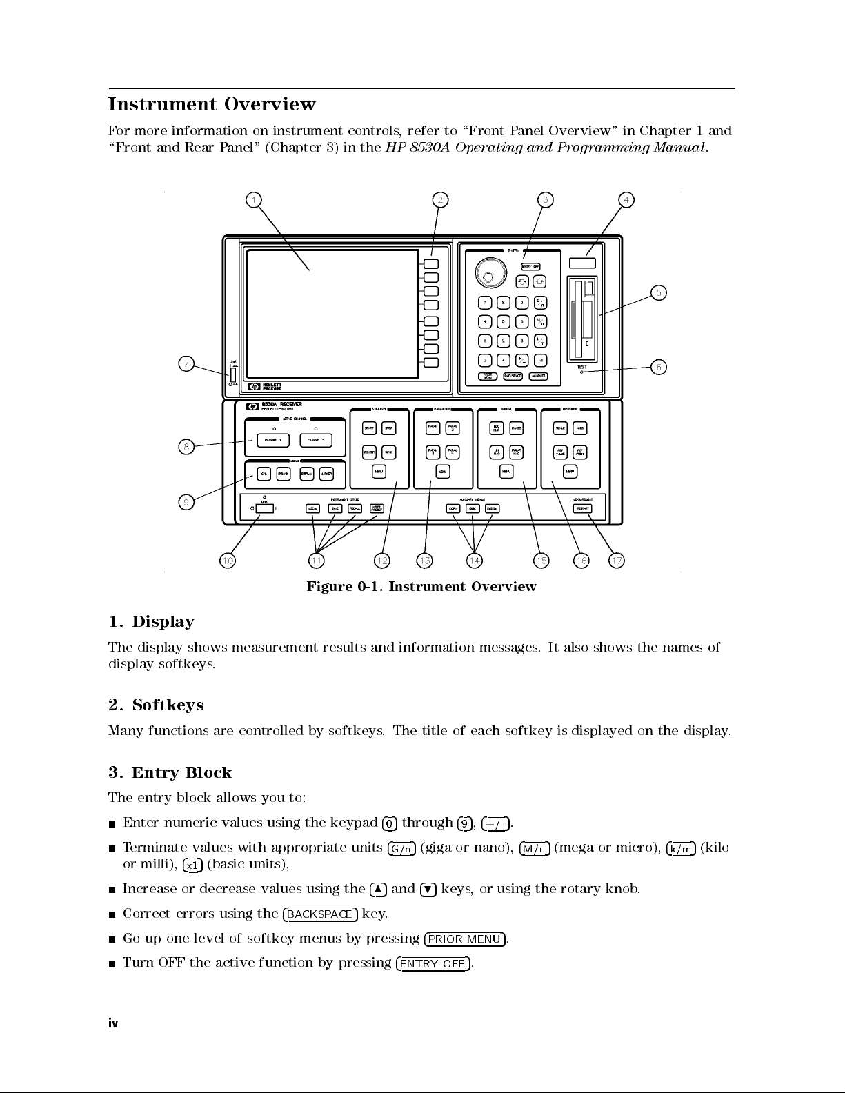
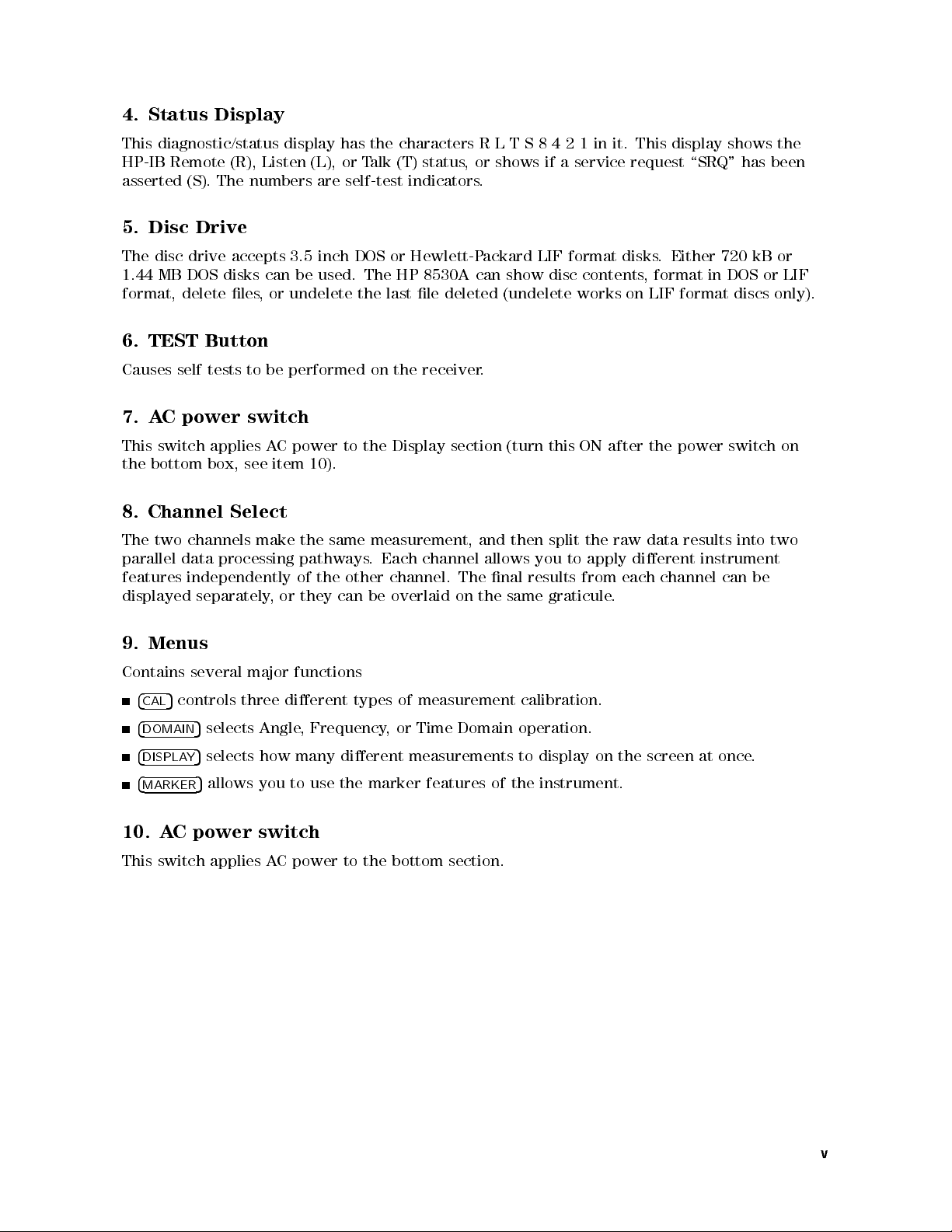
Instrument Overview
For more information on instrument controls, refer to \Front Panel Overview" in Chapter 1 and
\Front and Rear Panel" (Chapter 3) in the
HP 8530A Operating and Programming Manual
.
Overview
messages.
It also
shows the
names of
Display
1.
display
The
display
shows
softkeys
measurement
.
Figure
results
Instrument
0-1.
and
information
2. Softkeys
Many functions are controlled by softkeys. The title of each softkey is displayed on the display.
Entry
3.
The entry
Enter numeric values using
Terminate values with appropriate units
or milli),
Increase or decrease values using the
Correct errors using the
Go
Turn
Block
block allows you to:
4
5
(basic units),
x1
of
level
one
up
active
the
OFF
4
softkey
function
the keypad
BACKSPACE
menus by
pressing
by
485
5
key.
pressing
4
5
through
0
4
5
(giga or nano),
G/n
and
495
4
4
ENTRY
4
5,4
5
+/-
.
4
5
(mega or micro),
M/u
9
keys, or using the rotary knob.
.
5
MENU
PRIOR
.
5
OFF
4
k/m
5
(kilo
iv
4. Status Display
This diagnostic/status display has the characters R L T S 8 4 2 1 in it. This display shows the
HP-IB Remote (R), Listen (L), or Talk (T) status, or shows if a service request \SRQ" has been
asserted (S). The numbers are self-test indicators.
5. Disc Drive
The disc drive accepts 3.5 inch DOS or Hewlett-Packard LIF format disks. Either 720 kB or
1.44 MB DOS disks can be used. The HP 8530A can show disc contents, format in DOS or LIF
format, delete les, or undelete the last le deleted (undelete works on LIF format discs only).
6. TEST Button
Causes self tests to be performed on the receiver.
7. AC power switch
This switch applies AC power to the Display section (turn this ON after the power switch on
10).
item
see
the
bottom
box,
Channel
8.
two
The
parallel
features
displayed
Menus
9.
Contains
controls
4
5
CAL
4
DOMAIN
4
DISPLAY
4
MARKER
data
Select
the
channels
independently
separately
several
selects
5
5
selects how many dierent measurements to display on the screen at once.
5
allows you to use the marker features of the instrument.
make
processing
or
,
major
three
Angle
pathways
of
they
functions
dierent
,
10. AC power switch
power
C
This
switch
applies
A
measurement,
same
.
other
the
be
can
types
Frequency
to the
channel
Each
channel.
overlaid
measurement
of
Time
or
,
bottom
and
allows
nal
The
the
on
Domain
section.
split
then
you
results
graticule
same
calibration.
operation.
to
the
apply
from
raw
dierent
each
.
data
channel
results into
instrument
be
can
two
v

11. Instrument State
Contains several functions:
4
5
LOCAL
allows you to specify the HP-IB addresses of the receiver and \slave" instrument
connected to the System Interconnect. (The System Interconnect is the HP 8530A's
\personal" HP-IB bus. Any devices connected to it (printers, plotters, RF or LO sources) are
controlled exclusively by the HP 8530A.
4
5
and
SAVE
4
RECALL
5
allow you to save current measurement settings to one of eight save/recall
registers (for later recall).
4
USER PRESET
time you turn power ON or press
5
any setup you save in save register 8 becomes the \user preset" state. Any
4
USER PRESET
5
the settings stored in register 8 are retrieved.
12. Stimulus Block
The stimulus block controls most of the functions associated with the basic measurement setup.
Stimulus controls include:
Measurement start/stop or center/span values for angle, frequency,ortime.
ower
P
Sweep
Number
for
levels
(single
type
measurement
of
RF
and
sweep
sources
LO
continuous
,
points
.
Frequency
(in
sweeps
ramp sweep
,
Domain),
sweep,
,step
increment angle
or
and more).
(in Angle
Domain).
.
setup
mode
mode
selects
select
5
4
measured,
any
the
on
List
(internal,
osition
P
Encoder
which
dierent
and
measurement
four
the
of
b1,
a2,
a1,
external,
controls
8530A
HP
\ratioed"
are
then
results
input
input
b2
or
HP-IB).
or
.
measure
inputs
to
measurements
mathematically
.
lines
Softkey
lines
menus
without
.)
main keys
the
.
\Ratio"
.
divided
under
means
together
this
ratioing. (This
4
ARAM
P
test
a
that
method provides
This
.
block's
4
MENU
feature allows
through
5
1
and reference
allows
key
5
you to
check the
you
Frequency
Trigger
85370A
HP
arameter Block
P
13.
block
This
4
ARAM
P
are
signal
accurate
very
measure
to
signals
14. Auxiliary Menu
This area contains three control keys:
4
COPY
4
DISC
allows
5
allows
5
disc-related
4
SYSTEM
are controlled are: phase lock, IF calibration,
you
to save
drive
disc
the
use
to
you
functions
5
contains instrument conguration functions
.
or
power leveling, and multiple-source setup
measurement results
the
plot
or
print
to
(used when more than one source is connected to
load
the HP 8530A). The system key also has
.
format
,
les
Examples of the type of functions that
.
service menus that are used when troubleshooting the instrument.
15. Format Block
as
This block
allows
you
to
select
dierent
display
formats
such
log format.
vi
discs
Cartesian
,
and
or
perform
polar
other
or
linear
in
,
16. Response Block
This block controls the following:
Display scale
Position and value of the reference line
Automatic display scale (autoscale)
Measurement averaging
Trace smoothing
Trace \normalization" (A specic point on the measurement trace is set to 0 dB, and other
portions of the trace are displayed relative to that.)
Magnitude slope and oset control
Phase oset control
Coaxial, waveguide, or user-denable electrical delay selection
17.
4
RESTART
5
This
progress
in
key
is
used
If
.
when
you
are
you
using
are
making
the
single
swept
sweep
measurements
4
,
mode
REST
ART
.
It
5
can
aborts
start
measurement
any
new
a
sweep
that is
.
vii
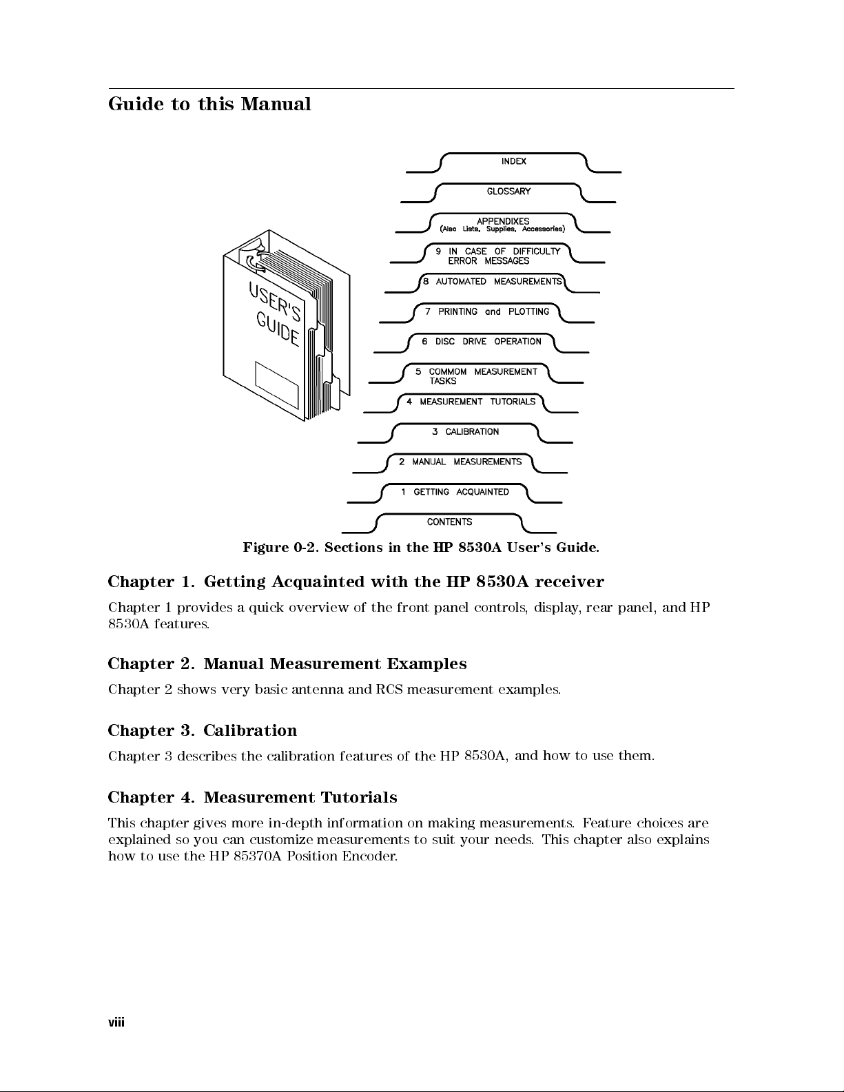
Guide to this Manual
Guide
receiver
display
,
Chapter
Chapter
8530A
features
Chapter
Figure
cquainted
quick
a
A
overview
1.
provides
1
Getting
.
Manual Measurement
2.
0-2. Sections
with
the
of
HP
the
in
HP
the
panel
front
Examples
8530A
8530A
controls
User's
Chapter 2 shows very basic antenna and RCS measurement examples.
Chapter 3. Calibration
how
Chapter
describes
3
calibration
the
features
of
the HP
8530A,
and
Chapter 4. Measurement Tutorials
This chapter gives more in-depth information on making measurements
explained
how to use
so you can customize measurements to suit your needs
the HP 85370A P
osition Encoder
.
. This chapter also explains
.
panel,
rear
,
them.
use
to
eature choices are
.F
and
HP
viii
Chapter 5. Common Measurement Tasks
Chapter 5 describes specic measurement tasks such as:
Finding boresight Using Markers
Determining 3 dB beamwidth Measuring depth of a null
Displaying data relative to the peak Displaying more than one trace
Using averaging Using frequency list mode
Chapter 6. Disc Drive Operation
Explains how to use the built-in disc drive to store and retrieve data, instrument state les,and
other types of information.
Chapter 7. Printing and Plotting
Describes how to output screen \snapshots" or tabular data to printer or plotter. A wide range
of HP printers and plotters are covered in detail.
Chapter
Chapter
use
to
how
receiver
Making
8.
explains
8
ast
F
the
automatically
to
utomated
A
measure
to
how
Multiplexing.
IF
switch
between
Measurements
5,000 points
up to
multiplexing
IF
ast
(F
dierent
per second
input
similar
is
ratios
at
using F
F
to
angle
each
CW
ast
ast CW
mode
,but
frequency
or
and
,
allows
the
point.)
Diculty
Chapter
chapter
This
solve
to
How
to
What
solve
to
How
Appendix
In
9.
explains:
when
do
A,
common
basic
Case
Optimizing
of
operation
specic
hardware
messages
error
problems
Dynamic
problems
.
displayed
are
Range
on
the
screen.
Conguring the system for optimum dynamic range entails using the highest RF power settings
possible without overdriving the receiver. Appendix A explains how to congure your system
so optimum dynamic range is available.
Compatible
,
Appendix
compatible
Lists
B
RF
and
plotters, and monitors
and P
converters
LO
Instruments
sources,
frequency
.
eripherals
positioner
,
controllers
printers
,
,
ccessories, After-Sale Options
Appendix C, Supplies
Lists commonly-needed supplies (plotter pens
,A
, paper
, discs) and after-purchase options (time
domain option, rack-mount hardware, connector savers, and touch-up paint).
Appendix
Explains
connector
Connector
,
D
care
Care
techniques
and
cleaning
procedures
.
ix

Other Manuals that Come with the HP 8530A
The following manuals are supplied with the HP 8530A:
Operating and Programming Manual
The Operating and Programming manual serves two purposes:
It provides in-depth reference information on front panel features, organized around the
front panel functional blocks.
It provides tutorial information on remote programming, with many HP BASIC examples.
Keyword Dictionary
The Keyword Dictionary explains:
The function of each front panel key or display softkey, organized by key/softkey name.
What each HP-IB programming code does, including syntax and programming sequence
details.
panel
Front
alphabetical
On-Site
The
Service
On-Site
Installation
Troubleshooting
Performance
Typeface
Bold
Italics
Computer
Display
4
anel Keys
Front P
NNNNNNNNNNNNNNNNNNNNNNNN
NNNNN
Soft Keys
key/softkey
.
order
and
Manual
tests
Manual
specications
and
Service
Conventions
Bold type is used for terms that are listed in the glossary.
Italic type is used for emphasis and for the titles of manuals and other
publications. It is also used when describing a computer
Computer
Display
receiver's
5
Front panel keys are enclosed in
Soft keys are the keys on the right-hand side of the display
function of
programming
contains:
type
is
type
display
these keys changes depending on the menu you are in.
code
used
is
used to
.
descriptions
depict
to
messages
show
coexist
HP-IB
boxes.
the
in
commands
which
are
section,
same
variable
.
displayed
the
on
.The
in
.
x

Getting Acquainted with the HP 8530A Receiver
Chapter Contents
Product Description
Receiver Performance
Measurement Features
Input/Output Features
Principles of Operation
Front Panel Overview
1
Getting
Acquainted with
the
HP
8530A
Receiver
1-1
Product Description
The HP 8530A is a high-performance receiver that has been designed specically for antenna
and radar cross section (RCS) measurements.
The HP 8530A allows you to make angle-scan and frequency-scan measurements of antennas,
or make RCS measurements using the time domain feature.
Very fast measurement speeds are possible with the HP 8530A. By using a computer controller,
the receiver can measure up to 5,000 data points per second.
The receiver has very high sensitivity and dynamic range. The HP 8530A provides a large
amount of measurement exibility, providing the features you need for many dierent types of
measurements.
The HP 8530A must be used with a frequency down converter. The following HP down
converters are supported:
HP 8511A/B frequency converter
HP 85310A distributed frequency converter
HP 85325 millimeter wave subsystems (the HP 85325A and HP 85309A, used together, make
a complete frequency converter system).
reference
and
test
MHz
the
to 20
basic
block
diagram
of
an
products down-convert
These
signals
antenna
that are
measurement
measured by
system.
microwave (or
the HP
8530A. Figure
millimeter) signals
shows
1-1
Getting Acquainted
1-2
with
the
HP
8530A
Receiver

Figure
1-1.
Basic
Antenna
Measurement
Block
Diagram
Receiver Performance
The most important feature of the HP 8530A is the accuracy and speed with which it makes
measurements. The important performance features are:
Excellent sensitivity.
.
Excellent
speed
High
linearity
over a
data acquisition
dynamic
wide
capability
range
.
Sensitivity
The foundation of good system performance
measure very small signals
. Excellent sensitivity
noise. When used with the HP 85310A frequency
and high speed is sensitivity|the ability to
is only possible in systems that have very low
converter, the HP 8530 can measure signals
of0113 dBm from 3 to 18 GHz, and096 dBm from 18 to 26.5 GHz. Excellent sensitivity
improves the signal-to-noise ratio of your system, allowing you to measure smaller signals more
quickly
,
and
with
greater
accuracy
.
Receiver
8530A
HP
Getting
Acquainted with
the
1-3
Linearity over a Wide Dynamic Range
Accuracy errors can occur when the power from the test antenna varies in signal level. For
example, assume that a test antenna has a bore-sight measurement of 0 dBi (020 dBm) and an
o-axis null of050 dBi (070 dBm). This is a dierence of 50 dB. The HP 8530A receiver has
0.03 dB of error in this case. Even with a 60 dB dierence the HP 8530A has less than 0.04 dB
of error due to linearity. This specication is called \dynamic accuracy."
Fast Measurement Speed
The HP 8530 can measure 5000 points per second. As mentioned earlier, averaging slows
measurement speed. Because of the HP 8530A's excellent performance, you will need less
averaging, and can make faster measurements, than you would when using a receiver with less
performance.
High speed measurements are performed using the \Fast CW" mode, and must be done through
computer control.
Getting Acquainted
1-4
with
the
HP
8530A
Receiver
Measurement Features
The major
operational
features of the HP 8530A are listed below:
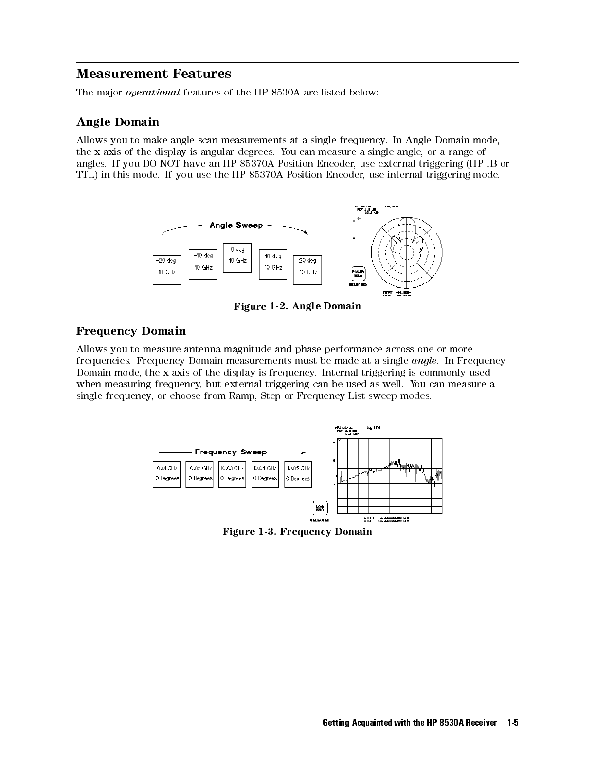
Angle Domain
Allows you to make angle scan measurements at a single frequency. In Angle Domain mode,
the x-axis of the display is angular degrees.You can measure a single angle, or a range of
angles. If you DO NOT have an HP 85370A Position Encoder, use external triggering (HP-IB or
TTL) in this mode. If you use the HP 85370A Position Encoder, use internal triggering mode.
Domain
phase
performance
must be
Internal
.
be
can
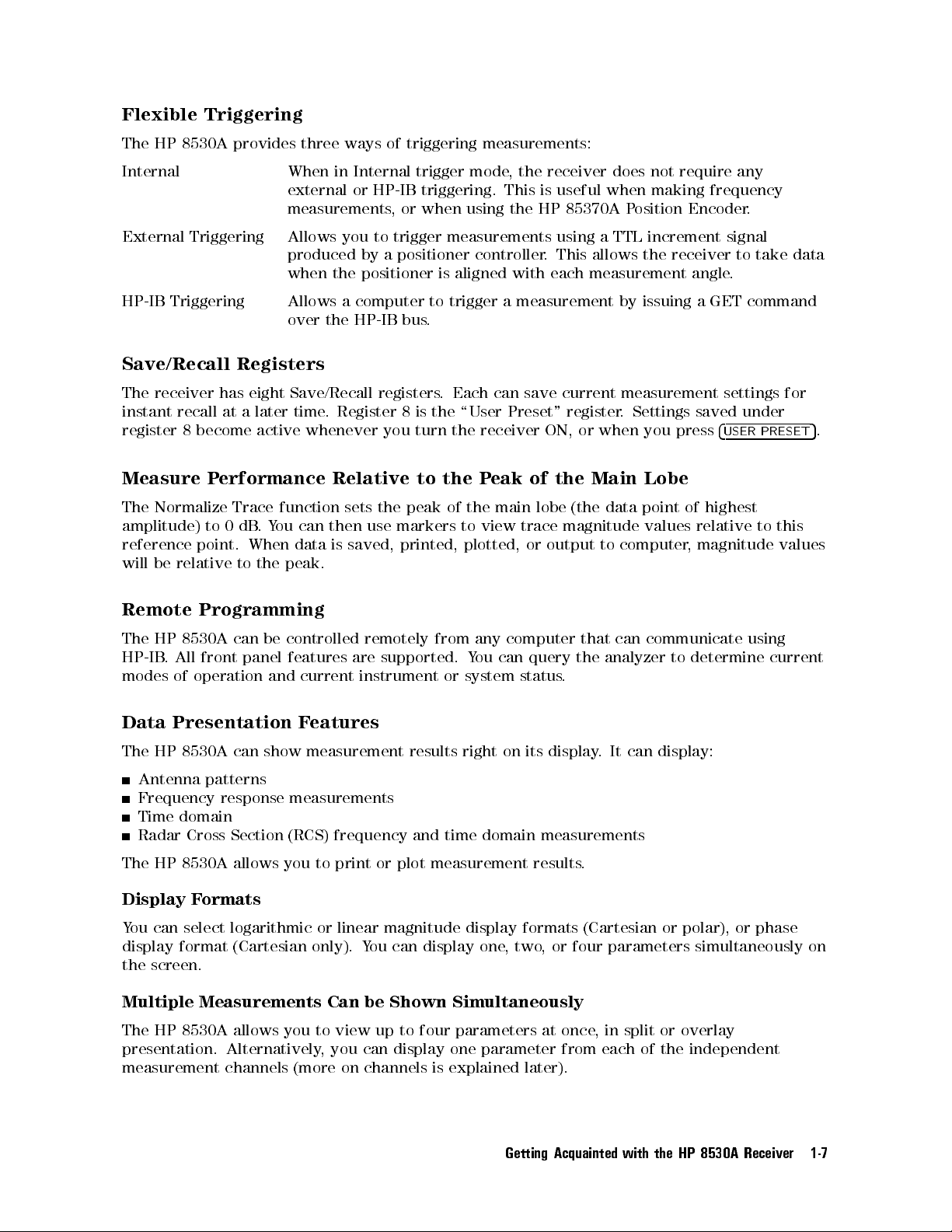
Frequency
made
used
List
across
single
a
at
triggering
well.
as
sweep
one
angle
commonly
is
ou
Y
modes
or
.
can
.
more
Frequency
In
used
measure
a
Frequency
Allows
frequencies
Domain
when
single
you
.
mode
measuring
frequency
Domain
measure antenna
to
Frequency
the
,
Domain
x-axis
frequency
choose
or
,
,
display
but
of the
from Ramp
Angle
Figure
1-2.
magnitude and
measurements
frequency
is
external triggering
or
Step
,
Figure
1-3.
Frequency
Getting
Domain
Acquainted with
the
HP
8530A
Receiver
1-5

Time Domain
This optional feature allows you to make RCS measurements or see the time response of an
antenna (time is shown on the displays x-axis). One use of time domain is when measuring
multi-path range reections. Internal triggering is usually used in this mode.
Time domain data is mathematically calculated from Frequency Domain data. This is done
using the \chirp-Z" inverse Fourier transform. Therefore, the rst step in time domain
measurements is to make a measurement in the Frequency Domain.
Domain
Time
Figure
1-4.
Calibration
Antenna
calibrating
reduces
A
make
the
measurement errors
\network
network
impedance
calibration
coupler
is
calibration provides
your range
analyzer"
against
calibration
analyzer-type
antenna
an
of
make
could
you
so
measure
required
to
accurate
standard
a
caused
gain
signal
by
provided.
also
is
measurements
output).
(or
input
accurate
very
reected
the
frequency
and
antenna.
gain
crosstalk.
example
or
F
.
ou would
Y
measurements.
signals.
This
response
the
,
Also
calibration
assume you
,
perform the
In this
measurements
isolation
is used
calibration
if you
want to
network
example a
by
feature
to
want
measure
analyzer
directional
Four Measurement Inputs
The receiver has four inputs for receiving signals (a1, a2, b1 and b2). You must input a
reference signal into a1 or a2. Then, any other inputs can be used as test signal inputs.For
example
test
carry
your
for
assume you
,
signals.
The
measurement.
input
ARAM"
\P
reference
the
keys
signal
described
,
into
below
a1.
Y
select
,
ou
could
which
then
inputs to
use a2,
b1,
ratio
together
to
b2
or
Selectable Input Ratios
4
PARAM 1
measure.
,
4
5
PARAM 2
,
4
5
PARAM 3
, and
5
4
PARAM 4
(\PARAM" is short for \parameter
, select a specic pair of inputs to ratio and
5
,
or example
.") F
4
PARAM 1
5
mathematically
divides
(ratios) input b1 data by a1 data. You can redene the PARAM keys so they ratio any two
inputs you desire.You can also measure a single input without ratioing.
Getting Acquainted
1-6
with
the
HP
8530A
Receiver
Flexible Triggering
The HP 8530A provides three ways of triggering measurements:
Internal When in Internal trigger mode, the receiver does not require any
external or HP-IB triggering. This is useful when making frequency
measurements, or when using the HP 85370A Position Encoder.
External Triggering Allows you to trigger measurements using a TTL increment signal
produced by a positioner controller. This allows the receiver to take data
when the positioner is aligned with each measurement angle.
HP-IB Triggering Allows a computer to trigger a measurement by issuing a GET command
over the HP-IB bus.
Save/Recall Registers
The receiver has eight Save/Recall registers. Each can save current measurement settings for
instant recall at a later time. Register 8 is the \User Preset" register. Settings saved under
register 8 become active whenever you turn the receiver ON, or when you press
4
USER PRESET
5
.
Measure
Normalize
The
amplitude)
reference
relative
be
will
Remote
8530A
HP
The
All
.
HP-IB
modes
Data
The
of
Presentation
8530A
HP
erformance
P
function
Trace
can
ou
Y
.
dB
0
to
the
data
peak.
point.
When
to
Programming
can be
front panel
operation
controlled
features
and current
Features
show measurement
can
Relative
sets
use
then
saved,
is
remotely
are
instrument or
to
peak
the
markers
printed,
from
supported.
results right
the
of
to
plotted,
any
ou
Y
system
main
view
computer
can
on its
lobe
trace
output
or
query
status
display
(the
magnitude
to
that
the
.
.
Main
the
of
eak
P
the
Antenna patterns
Frequency response measurements
Time domain
Radar Cross Section (RCS) frequency and time domain measurements
8530A
HP
The
Display F
allows
ormats
you
print
to
You can select logarithmic or linear
display format (Cartesian only). Y
plot measurement
or
results
magnitude display formats (Cartesian or polar), or phase
ou can display
one,two, or four parameters simultaneously on
.
the screen.
Lobe
point
data
values
computer
communicate
can
analyzer
can
It
of
relative
magnitude
,
determine
to
display:
highest
to this
values
using
current
Multiple Measurements Can be Shown Simultaneously
The HP 8530A allows you to view up to four parameters at once, in split or overlay
independent
the
of
presentation.
measurement
Alternatively
channels
(more
,
you
on
display
can
channels
one
explained
is
parameter from
later).
Getting
Acquainted with
each
the
HP
8530A
Receiver
1-7

Trace Memory and Trace Math
The trace memory feature is similar to the storage feature in a storage oscilloscope.You can
store the current data trace to memory, then compare it to subsequent measurement traces.
Trace math features allow you to perform vector addition, subtraction, multiplication, and
division. These operations are performed using the current data trace and the memory trace.
Each parameter has independent trace memory/math operation. In addition, trace math in
Channel 1 is independent from trace math in Channel 2.
Markers Display Precise Values for Any Point on display Traces
Five measurement markers give detailed information about any point on the measurement
trace. Delta markers allow you to show the dierence in amplitude, phase, angle,ortime
between any two points on the screen.
External Video Monitor
The HP 8530A can display results on an external multisync monitor. Refer to Appendix B for
details.
Optional Network Analysis
Option
This
011
allows
frequency
accuracy
adds
you
or
in
high-performance
measure
to
optional
arameter
S-P
time
the
domains
network
vector
network
transmission
These
.
measurements
analysis
reection
and
advanced
.
features
properties
calibration
(HP
of
features
8510C
operation).
microwave
provide
devices
optimum
in
Getting Acquainted
1-8
with
the
HP
8530A
Receiver

Input/Output Features
The HP 8530A can control other instruments, and has many input/output capabilities using
HP-IB, System Bus, RS-232, external monitor interface, and TTL BNCs.
Printing and Plotting Features
The HP 8530A can output data to a wide range of HP-IB or RS-232 printers or plotters. Laser
printers are also supported.
Many Supported Peripherals
The HP 8530A can control RF and LO signal sources, frequency converters, and large external
display monitors. Refer to Appendix B for details.
Built In Disc Drive
The built in disc drive allows you to save measurement data, data from memory, instrument
conguration setups, save/recall registers, calibration data, or user-created graphics. Both
LIF
and
DOS
format
DOS
format
LIF
workstation
formats
disc
compatible
is
compatible
is
family
are
with
with
supported,
MS-DOS
Hewlett-P
and
R
based
ackard
computers
computers
,
,
such
such
as
as
IBM
the
PCs
HP
automatically
are
types
disc
both
.
recognized.
compatibles
and
9000 Series
300
.
Getting
Acquainted with
the
HP
8530A
Receiver
1-9
Principles of Operation
This information is provided so you can have a better understanding of how the HP 8530A
makes measurements. If desired, you can skip this section and come back to it when
convenient.
Description of the HP 8530A
A simplied block diagram of the HP 8530A receiver is shown in Figure 1-5. It is a high
performance vector receiver with four inputs, two independent digital processing channels,and
an internal microcomputer that controls measurement, digital processing, and input/output
operations. Examples of \digital processing" are features such as averaging, time domain,
calibration, and so on. A special System Bus gives the receiver complete control over the
RF source and, if required, LO source. This interface allows the receiver to make hard copy
outputs to HP-IB compatible printers or plotters. Two RS-232 ports are also supplied for
printing or plotting.
The system must contain a frequency converter, which down converts the RF measurement
frequencies to a 20 MHz IF. The HP 8530A requires this frequency for its inputs.To create
the IF frequency, the HP 8511A/B frequency converter uses a built-in local oscillator. The
est
\T
the
over
is
built-in
Set
LO
Interconnect"
measurement
signal.
IF
MHz
LO
supply
the
an
System
Bus
digitally
that
signals
Other
signal.
.
tuned
links
with
down
The
the
by
HP
the
similar
a
converters
8530A
HP
8530A. This
HP
8530A
and
frequency
such
,
external
tunes
that
as
digital tuning
the HP
oset by
is
HP 85310A,
the
LO
data is
8511A/B.
The local
20 MHz.
require another
sources with
sent
oscillator mixes
The result
is the
source
HP-IB commands
to
sent
the
20
over
Getting Acquainted
1-10
with
the
HP
8530A
Receiver
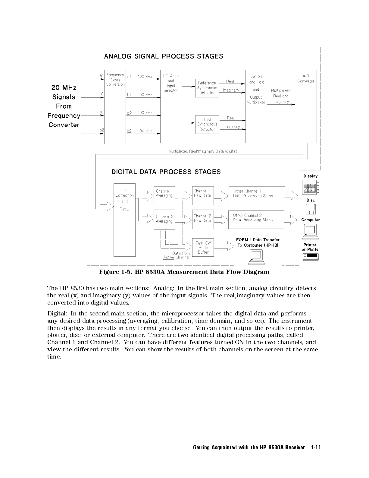
Figure
1-5.
HP
8530A
Measurement
Data
Flow
Diagram
The
HP
8530
has
two
main
sections:
Analog:
In
the
main section,
rst
analog circuitry
detects
the real (x) and imaginary (y) values of the input signals. The real,imaginary values are then
converted into digital values.
Digital: In the second main section, the microprocessor takes the digital data and performs
any desired data processing (averaging, calibration, time domain, and so on). The instrument
results
disc
,
and
or
the
external
Channel
displays
then
plotter,
Channel 1
view the dierent results
results
output
then
can
ou
Y
two
.
identical
features
digital
turned
processing paths
ON
choose
There
.
have
you
are
dierent
any format
in
computer
can
ou
Y
2.
ou can show the results of both channels on the screen at the same
.Y
the
in the
two
to printer
called
,
channels
,
and
time.
Receiver
8530A
HP
Getting
Acquainted with
the
,
1-11
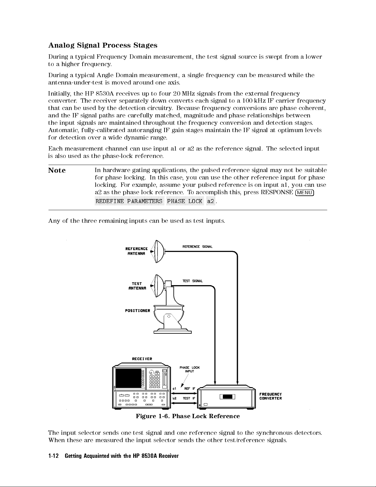
Analog Signal Process Stages
During a typical Frequency Domain measurement, the test signal source is swept from a lower
to a higher frequency.
During a typical Angle Domain measurement, a single frequency can be measured while the
antenna-under-test is moved around one axis.
Initially, the HP 8530A receives up to four 20 MHz signals from the external frequency
converter. The receiver separately down converts each signal to a 100 kHz IF carrier frequency
that can be used by the detection circuitry. Because frequency conversions are phase coherent,
and the IF signal paths are carefully matched, magnitude and phase relationships between
the input signals are maintained throughout the frequency conversion and detection stages.
Automatic, fully-calibrated autoranging IF gain stages maintain the IF signal at optimum levels
for detection over a wide dynamic range.
Each measurement channel can use input a1 or a2 as the reference signal. The selected input
is also used as the phase-lock reference.
Note
Any
of
the
In hardware gating applications, the pulsed reference signal may not be suitable
for phase locking. In this case, you can use the other reference input for phase
you
a1,
input
on
press
,
is
RESPONSE
three
locking. F
the phase
a2 as
NN
N
N
N
N
N
N
N
N
N
N
N
N
N
NN
NN
NN
REDEFINE
remaining
example
or
lock
N
N
N
N
NN
NN
NN
NN
N
N
N
N
N
N
N
N
PARAMETERS
inputs
N
N
N
N
N
N
N
N
N
N
can
assume
,
reference
N
NN
NN
N
N
N
NN
NN
NN
N
N
N
N
PHASE
used
be
N
N
NN
your
.
N
N
N
N
as
pulsed
accomplish
o
T
N
NN
N
N
N
N
N
N
N
N
N
N
N
LOCK
test
reference
NN
NN
N
N
N
N
.
a2
inputs
this
.
4
MENU
can
use
5
input
The
these
When
Getting Acquainted
1-12
selector
measured
are
sends
with
one
the
the
Figure
test
input
8530A
HP
signal
selector
1-6.
and
Receiver
Phase
reference
one
sends the
Lock
Reference
signal
test/reference
other
to
synchronous
the
signals
detectors
.
.
The synchronous detectors develop the real (x) and imaginary (y) parts of the test or
reference signal by comparing the input to an internally-generated 100 kHz sine wave. This
method practically eliminates drift, osets, and circularity errors as sources of measurement
uncertainty. Each x,y pair is sequentially converted to digital values which are sent to the
main microprocessor.
Digital Data Process Stages
Digital signal processing proceeds under the control of the receiver's rmware operating system
executed by the main microprocessor.
About the Main Microprocessor
The main microprocessor is a 32-bit Motorola 68020 microprocessor running at a clock speed of
16 MHz. The rmware operating system takes advantage of multi-tasking software architecture
and several distributed processors to provide very fast data acquisition and display update
speed.
Raw Data Stages
The microprocessor accepts the digitized real and imaginary data, and corrects IF gain and
quadrature
correction
IF
the
in
automatic
by
way
any
errors
feature
the
before
is
user
any
are
stage
dierent
.
data
other
calculated
the
from
processing
is done
periodically with
calibration
user
. The
an automatic
features
,and
calibration coecients
self-calibration. This
cannot be
controlled
used
in
independent
to
sent
are
data
the
F
1
is
orm
of
Channel
or
channel
raw
1
.
one
holds
described
if
format.
1
data
you
.
X,Y
in
are
2.
ast CW
F
If
array
data
the
using
the
If
Similarly
.
HP
pair
the
ast
F
mode
in
8530A
F
mode
CW
is
Channel
,
special
a
eyword
K
CW
ast
not
is
being
mode
inputs
the
Next,
Channel
and
any
,
,
use
Channel
\arrays"
1
selected
data
data
sent
is
1
is stored
are data
Channel
Now
in
used,
averaged
Data
compressed data
Dictionary
buer
The
The F
.
contains up
ratioed
are
data
2
averaging
ast
F
the
to
averaged
data
in the
holding locations
format called
ast CW
buer can
to 100,000
together
processing
performed
is
buer
CW
stored
is
Channel
\Form
X,Y data
identical
and
paths
on
from
in
raw
2
A
.
1." This
data
send
Channel
the
data
data
pairs
copies
.
active
the
Channel
array
array
format
computer
to
in
Other Digital Processing Stages
Channel 1 and 2 data processing proceeds independently through subsequent data processing
steps. Dierent measurement features can be used in each channel, causing the measurement
shown
be
results
to
Processing"
on. F
so
and
Domain
in Channel 1. This allows you to make two dierent types of measurements on the
same device
processed
steps
example
or
, and display the results simultaneously
and
shown in
you
,
Figure
can
More information on the \other"
Operation," later in this guide
.
\Other
the
Time
and select
2,
are
Domain,
in dierent
and
,
1-5
Time
select
ways
include
Domain
features
These
.
calibration,
Channel
in
.
data processing steps is provided in \Standard A
Data
display
format,
Frequency
utomated
2
.
Getting
Acquainted with
the
HP
8530A
Receiver
1-13
Front Panel Overview
Front Panel Overview
This section describes the receiver's display and the purpose of the major control blocks. Note
that you can press any key, at any time, and in any sequence without fear of damaging the
system.
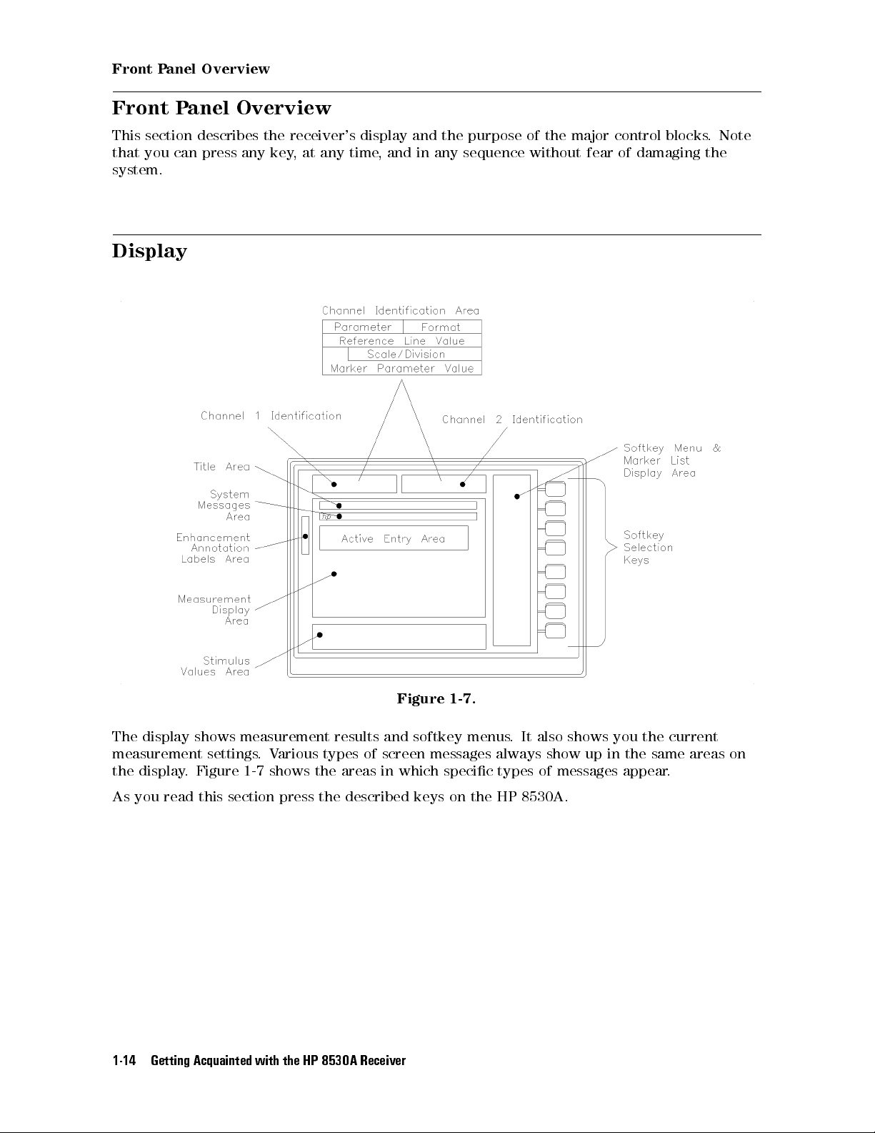
Display
Figure 1-7.
The display shows measurement results and softkey menus. It also shows you the current
measurement settings.Various types of screen messages always show up in the same areas on
the display. Figure 1-7 shows the areas in which specic types of messages appear.
8530A.
HP
the
read
you
As
Getting Acquainted
1-14
this
section
with
press
the
described keys
the
8530A
HP
Receiver
on
Front Panel Overview
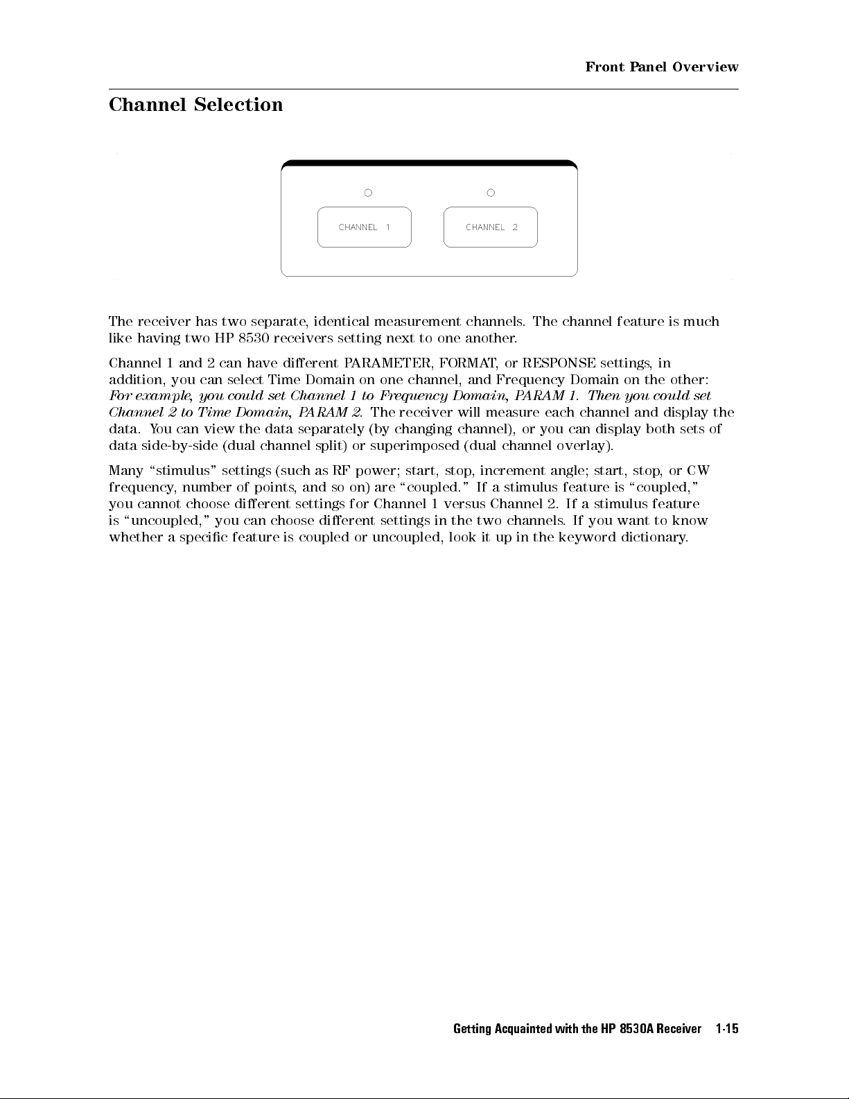
Channel Selection
The receiver has two separate, identical measurement channels. The channel feature is much
like having two HP 8530 receivers setting next to one another.
Channel 1 and 2 can have dierent PARAMETER, FORMAT, or RESPONSE settings,in
addition, you can select Time Domain on one channel, and Frequency Domain on the other:
For example, you could set Channel 1 to Frequency Domain, PARAM 1. Then you could set
display
display
and
both
sets
Time
to
Channel
data. Y
2
ou can
view the
data side-by-side
Domain,
P
data separately
(dual channel
ARAM
split) or
receiver
The
2.
changing
(by
superimposed (dual
measure
will
channel),
channel
or
each
can
you
overlay).
channel
the
of
\stimulus"
Many
frequency
cannot
you
\uncoupled,"
is
whether
a
number
,
choose
specic
settings (such
points
of
dierent
choose
can
you
feature
is
as RF
and
,
settings
dierent
coupled
so
power;
are
on)
Channel
for
settings
uncoupled,
or
,
stop
start,
\coupled." If
versus
1
the
in
look
increment
a stimulus
Channel
channels
two
in
up
it
angle;
start,
feature
a stimulus
If
2.
If you
.
the keyword
,
stop
\coupled,"
is
feature
to
want
dictionary
CW
or
know
.
Getting
Acquainted with
the
HP
8530A
Receiver
1-15
Front Panel Overview
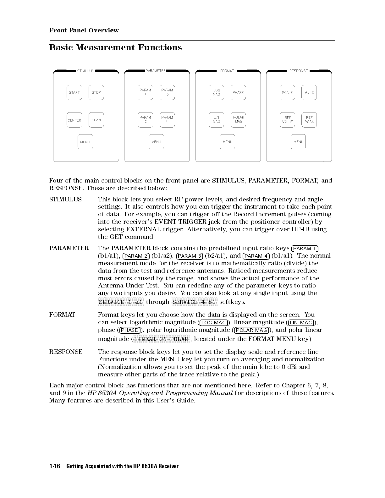
Basic Measurement Functions
Four of the main control blocks on the front panel are STIMULUS, PARAMETER, FORMAT,and
RESPONSE.
These
STIMULUS This
settings
of
into
selecting
the
described
are
block
data.
the
GET
It
.
or
F
receiver's
EXTERNAL
command.
below:
you
lets
controls how
also
example,
select
you can
EVENT
trigger
RF
power
levels
you can
trigger
TRIGGER jack
Alternatively
.
,
trigger
the
o
from the
,
desired
and
the
Record
you can
frequency
instrument
Increment
positioner
trigger
and
take
to
pulses
controller)
HP-IB
over
angle
each
(coming
using
point
by
4
keys
ratio
and
Ratioed
the
the
of
any
at
input
4
P
ARAM
5
4
ratio
measurements
actual
performance
parameter
single
.
(b1/a1).
(divide)
keys
input
ARAM
P
The
reduce
to
using
the
of
ratio
the
ARAMETER
P
ARAMETER
P
The
(b1/a1),
4
ARAM
P
measurement
the
from
data
errors
most
Antenna
any
N
N
N
N
N
N
N
SERVICE
Under
two inputs
N
N
N
N
N
N
N
N
N
NN
NN
NN
NN
N
N
N
1
N
N
2
mode
test
caused
T
you
N
NN
N
N
N
N
N
N
through
a1
block
(b1/a2),
5
for
and
by
est.
desire
contains
4
ARAM
P
receiver
the
reference
range
the
can
ou
Y
Y
.
N
N
N
N
N
N
N
N
N
SERVICE
,
redene
can
ou
N
N
NN
NN
NN
NN
N
predened
the
(b2/a1),
5
3
to
is
antennas
shows
and
any
also
NN
N
N
N
N
N
N
N
N
N
N
N
N
N
N
N
b1
4
mathematically
.
look
N
softkeys
FORMAT Format keys let you choose how the data is displayed on the screen. You
can select logarithmic magnitude (
RESPONSE
phase (
magnitude (
The
Functions
(Normalization
measure other
4
5
PHASE
), polar logarithmic magnitude (
NNNNNNNNNNNNNNNNNNNNNNNNNNNNNNNNNNNNNNNNNNNNNNN
LINEAR ON POLAR
response block
under
the MENU
allows you to set the peak of the main lobe to 0 dBi and
parts of the trace relative to the peak.)
keys
let
Each major control block has functions that are not mentioned here
and 9 in the
HP 8530A Operating and Programming Manual
Many features are described in this User's Guide
4
LOG MAG
5
), linear magnitude (
4
POLAR MAG
5
), and polar linear
4
, located under the FORMAT MENU key)
reference
and
averaging
on
scale
normalization.
and
you
key
to
let
set
you
the
turn
display
. Refer to Chapter 6, 7, 8,
for descriptions of these features
.
LIN MAG
line.
5
1
normal
the
5
),
.
Getting Acquainted
1-16
with
the
HP
8530A
Receiver

ENTRY Block
Front Panel Overview
cases
some
In
frequency
digits
4
k/m
entering
to
the
.
terminate
(kilo/milli)
5
and
8
Changing
it
The
data
keys
9
Values
necessary
is
keypad
digit
10
value
the
4
and
with
x1
the
(basic
5
allow values
Using the
supply
to
used
is
appropriate
the
with
units:
keypad, the
to be
Numeric
numeric
supply
to
dBm,
,
dB
knob can
changed
values
units
degrees
be
steps
in
eypad
K
these
.
used
.
a
for
values
Use
seconds
,
to
specic
The
.
4
(Giga/nano),
5
G/n
,
make
function,
keys
applicable
as
Hz)
continuous
such
the
to
4
M/
adjustments
the
of
right
(Mega/micro),
5
addition
In
.
,
while
or
angle
as
To change a value using the numeric keypad:
1. Select the function (start angle, frequency, or any other function that requires a value). This
function becomes the \active function."
4
the
the
entire
and
4
CKSP
BA
value).
.
4
5
0
+/
(If you
.
key
5
CE
A
+/
5
0
have
changes
already
.
toggle
the
pressed
sign of
Enter
2.
number
the
terminator
a
erminate the
3. T
new value
the
decimal,
,
press
,
the
If you
.
key
make
, you
using
must
numeric
mistake
a
re-enter
entry with the appropriate units
Getting
Acquainted with
the
HP
8530A
Receiver
1-17

Front Panel Overview
Table 1-1. Numeric Value Terminator Key Usage
Key
Angle Frequency Power Power Slope Time
Name
G/n { GHz { { ns
M/
{ MHz { {
s
k/m milli degrees kHz { { ms
1
1
x1
4x15
degrees Hz dBm dB/Ghz s
always represents single units.
Other Keys in the Entry Block
4
PRIOR MENU
4
=MARKER
4
=MARKER
5
takes you to the previous softkey menu.
5
can be useful when you are using markers. The easiest way to explain what
5
does is by example. Assume you are making a frequency response measurement,
and the last marker you moved (the active marker) is sitting at 11 GHz. Now assume you want
to change the start frequency to 11 GHz. All you need to do is press
4
START54=MARKER
5
.The
marker position (11 GHz) will become the start frequency.
value
line
4
STOP
to another
the
to
4
V
REF
marker
5
value
ALUE
.
4
=MARKER
function.
of
4
5
=MARKER
the
.
5
active
5
,
As
and
an
marker
the
could
ou
Y
Another
example
example
(for
display
have
way to
assume
,
assume the
,
reference
the
set
use
4
=MARKER
you want
line
frequency
stop
5
to set
marker value
change
will
transfer the
is to
the
to the
11
to
display
0
is
value
GHz
marker
reference
dB).
13.2
of
pressing
by
the
Press
active
4
ENTRY
OFF
function
function.
removes
5
text"
are
error
old
messages
messages
START
like
or
0
active
90
that
function
appear
text
when
from
you
screen.
the
changed
the
ctive
\A
value
of
a
Getting Acquainted
1-18
with
the
HP
8530A
Receiver

MENUS Block
Front Panel Overview
The four keys under MENUS are
CAL Softkeys under
4
5,4
CAL
DOMAIN
4
5
allow you to perform an antenna, radar cross section
CAL
5,4
DISPLAY
5
, and
4
MARKER
5
:
(RCS) or limited network analyzer calibration.
DOMAIN The HP 8530 has three modes of operation, called domains. These are the
Frequency, Angle, and optional Time Domain.
DISPLAY Softkeys under
4
DISPLAY
5
:
Place one, two, or four parameter measurements on the screen at once.
are:
memory.
colors
an
for
traces.
.
external
to
up
desired
a
monitor
markers
ve
point
on
.
Each
.
the
MARKER
the data
Saves
Displays
erforms trace
P
Allows
Allows
Softkeys
marker
memory traces
you
you
under
shows
measurement
Simple
4
Marker
Marker
markers
marker
search
list
trace to
math functions
change display
to
choose video
to
4
MARKER
amplitude
Marker
.
trace
the
on
.
mode
modes
.
modes
temporary storage
.
on memory
intensity or
settings for
to
you
allow
5
or
phase
values
Functions
display
trace
.
activate
.
Getting
Acquainted with
the
HP
8530A
Receiver
1-19
Front Panel Overview
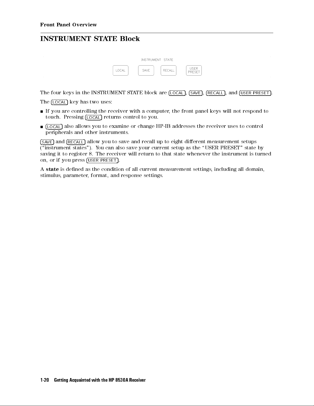
INSTRUMENT STATE Block
The four keys in the INSTRUMENT STATE block are
The
4
5
LOCAL
key has two uses:
4
LOCAL
5,4
SAVE
5,4
RECALL
5
, and
4
USER PRESET
If you are controlling the receiver with a computer, the front panel keys will not respond to
touch. Pressing
4
5
LOCAL
also allows you to examine or change HP-IB addresses the receiver uses to control
4
LOCAL
5
returns control to you.
peripherals and other instruments.
4
5
and
SAVE
4
RECALL
5
allow you to save and recall up to eight dierent measurement setups
(\instrument states"). You can also save your current setup as the \USER PRESET" state by
turned
saving
or
on,
state
A
stimulus
register
to
it
you
if
dened
is
parameter
,
press
8.
4
USER
the
as
format,
,
receiver
The
PRESET
condition
5
and
will
.
all
of
response
return
current
settings
state
that
to
measurement
.
whenever
settings
instrument
the
including
,
is
all domain,
5
.
Getting Acquainted
1-20
with
the
HP
8530A
Receiver
 Loading...