


Safety Summary
When you notice any of the unusual conditions listed below, immediately
terminate operation and disconnect the power cable.
Contact your local Agilent Technologies sales representative or
authorized service company for repair of the instrument. If you continue
to operate without repairing the instrument, there is a potential fire or
shock hazard for the operator.
n Instrument operates abnormally.
n Instrument emits abnormal noise, smell, smoke or a spark-like light
during the operation.
n Instrument generates high temperature or electrical shock during
operation.
n Power cable, plug, or receptacle on instrument is damaged.
n Foreign substance or liquid has fallen into the instrument.


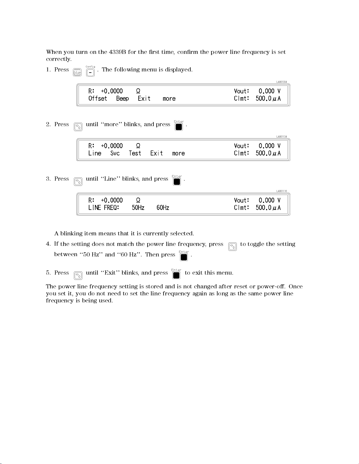
When
you
correctly
.
turn
on
the 4339B
for the
rst time
, conrm
the power
line frequency
is set
1. Press
2.
Press
3.
Press
A
blinking
until
until
item
. The
following menu
``more''
``Line''
means
blinks
blinks
that
,
,
it
is
is displayed.
and
press
and press
currently
.
.
selected.
4.
If
the
setting
between
5.
Press
The power
you set
it, you
frequency is
does
``50
Hz''
until
line
frequency
do
not
being used.
not
and
``Exit''
need
match
``60
blinks,
setting
to
the
Hz''.
set
power
Then
and press
is
stored
the
line
line
frequency
press
and
is
frequency
.
to
not
,
exit
this menu.
changed
again
press
as
long
after
reset
as
to
the
toggle
or
power-o.
same
the
power
setting
Once
line


Agilent
4339B High
Resistance
Operation Manual
Meter
This
number
F
manual
or
additional
numbers
applies
prex
,
read
SERIAL
directly
JP1KD
,
important
\Serial
NUMBERS
to
instruments
or
rmware
information
Number"
revision
about
in
Appendix
with
serial
serial
1.04.
A.
Agilent Part No. 04339-90060
Printed in Japan March 2003
Ninth Edition
Notice
The
information
This
document
reserved.
language
contains
No
part
without
contained
proprietary
of
this
the
prior
in
this
document
written
document
information
may
be
consent
is
subject
that
is
photocopied,
of
the
Agilent T
to
change
protected
reproduced,
echnologies.
without
by
copyright.
or
notice
.
All
translated
rights
are
to another
Agilent
T
echnologies
Component
1-3-2,
Murotani,
Hyogo
,
651-2241
T
est
Japan,
PGU-Kobe
Nishi-ku,
Japan
Ltd.
Kobe-shi,
c
1996, 1998, 1999, 2000, 2001, 2002, 2003 Agilent Technologies Japan, Ltd.

4339B
Manual Printing
March
December
June
A
July
March
January
September
March
ugust
1999
1996
1998
1998
2000
2003
1996
:
:
2001
2002
:
:
:
:
:
:
:
:
:
:
:
:
:
:
:
:
:
:
::
::
::
:
:
:
:
:
:
:
:
:
:
:
:
:
:
:
:
::
:
:
:
:
:
::
::
:
:
:
:
:
::
:
:
:
:
:
:
:
::
::
::
History
::
::
::
::
::
::
::
::
::
::
::
::
::
::
::
::
::
::
::
:
:
::
::
:
:
:
:
::
::
::
:
:
:
:
:
::
::
::
:
:
:
:
:
:
:
:
::
::
::
:
:
:
:
:
:
:
:
:
:
:
::
::
::
::
:
First
Edition (part
::
::
::
:
:
:
:
:
:
:
:
:
:
:
::
::
::
Second Edition
:
:
:
:
:
:
:
:
:
:
:
::
::
::
::
::
::
:
Third
Edition
:
:
:
:
:
:
:
:
:
:
:
:
:
:
:
:
:
::
::
::
:
F
ourth
Edition
:
:
:
:
:
:
:
:
:
:
:
:
:
:
:
::
::
::
::
:
:
Fifth
Edition
:
:
:
:
:
:
:
:
:
:
:
:
:
::
::
::
::
:
:
:
:
Sixth
Edition
:
:
:
:
:
:
:
:
:
:
:
:
:
:
:
::
::
::
:
Seventh
:
:
:
:
:
:
:
:
:
:
:
:
:
:
:
:
:
:
:
::
::
Eighth Edition
:
:
:
:
:
:
:
:
:
:
:
::
::
::
:
:
:
:
:
:
:
Ninth
Edition
Edition
number: 04339-90010)
(part number:
(part
number:
(part
number:
(part
number:
(part
number:
(part
number:
(part
number:
(part
number:
04339-90020)
04339-90030)
04339-90040)
04339-90050)
04339-90050)
04339-90050)
04339-90050)
04339-90060)
iii

Safety Summary
The
following
service
W
ARNINGS
In
addition
,
and
elsewhere
it
general
repair
violates
safety
of this
in
safety standards
instrument.
The
A
gilent
requirements
T
echnologies assumes
.
precautions must
instrument. F
this manual
no liability
be observed
ailure to
may impair
of design,
for the
during all
comply with
the protection
manufacture,
customer's failure
phases of
these precautions
provided by
and intended
the equipment.
use of
to
comply
operation,
or with
the
with
4339B
specic
these
Note
4339B
61010-1
4339B
Note
LEDs
CLASS
Ground
T
o
avoid
safety
DO
Do
not
electrical
Keep
earth
NOT
operate
A
way
The
Instrument
electric
shock
ground
Operate
the
instrument
From
Operating personnel
adjustments
with
the
with
the
circuits
power
power
before
must
cable
cable
touching
be
is
designed
and
is
an
INDOOR
in
4339B
1
LED
hazard,
by
the
supplied
In
An
instrument
in
such
Live
must
not
made
by
connected.
removed.
them.
for
use
POLLUTION
USE
are
Class
PRODUCT
the
instrument
power
Explosive
in
the
presence
an
environment
Circuits
remove
instrument
qualied
Under
T
o
avoid
in
INST
ALLA
DEGREE
product.
1
in
accordance
chassis
cable
with
Atmosphere
of
ammable
constitutes
covers
maintenance
certain
injuries
conditions
,
always
TION
1
according
with
and
earth
a
.
Component
personnel.
,
disconnect
CA
TEGORY
to
IEC60825-1.
cabinet
blade
.
gasses
denite
Do
dangerous
II
IEC
61010-1
must
be
or
fumes
safety
replacement
not
replace
voltages
power
according
and
connected
.
Operation
hazard.
components
may
and
discharge
IEC
and
exist
to
IEC
60664-1.
to
a
of
internal
even
any
DO
NOT
Service
Or
A
djust
Alone
Do not attempt internal service or adjustment unless another person, capable of rendering rst
aid and resuscitation, is present.
DO NOT Substitute P
Because of the danger of introducing additional hazards
arts Or Modify Instrument
, do not install substitute parts or
perform unauthorized modications to the instrument. Return the instrument to a Agilent
T
echnologies Sales and Service Oce for service and repair to ensure that safety features are
maintained.
iv

4339B
Dangerous
W
arnings
this
W
arning
,
manual.
Procedure
such
as
the
example
Instructions
contained
Dangerous voltages
instrument. Use
this instrument.
W
arnings
below
in
, capable
extreme caution
,
precede
the
warnings must
potentially dangerous
be followed.
of
causing
death,
when handling,
procedures throughout
are
present
testing,
in
and
this
adjusting
v
Certication
4339B
Agilent
of
T
echnologies
shipment
measurements
T
echnology
facilities
W
arranty
This
of
Agilent
,
to
other
workmanship
certain
specied
repair
F
or
Agilent
T
echnologies
pay
another
Agilent
T
echnologies
property
of
components
or
warranty
Technologies
all
shipping
country
T
echnologies
the
instrument,
period.
replace
installed
certies
from
the
are
traceable
the extent
International
T
echnologies
for
a
period
listed
During
products
service
.Buyer
shall
pay
charges
.
warrants
for
use
with
on
or
factory.
to
allowed by
instrument
of
in
General
the warranty
that
or
repair
shall
shipping
,
duties
an
instrument
that
instrument.
software
that this
Agilent T
the United
product met
echnologies further
States National
the Institution's
Standards Organization
one
year
product
from the
is
warranted against
date of
Information
period, Agilent
prove to
,
this
prepay
charges
,
and
that
,
or
be defective
product
shipping
to
taxes
its
software
will
Agilent
rmware
must
return
for
products
execute
T
will
and
echnologies
be
its published
certies that
Institute of
calibration facility
members.
shipment, except
of
this manual,
Technologies
.
be returned
charges
the
to
product
Agilent
returned
rmware
its
programming
does
uninterrupted
specications at
its calibration
Standards and
,or
defects in
the
warranty
will,
at
to
a
service
T
echnologies
to
Buyer
.
However
to
Agilent
designated
instruction
not
warrant
or
error
to the
material and
that
in
its
option,
facility
T
echnologies
by
Agilent
that
free.
the time
calibration
the
case
of
shall
be
for
either
designated
and
Agilent
,
Buyer
shall
from
when
the operation
the
by
Limitation
The
foregoing
maintenance
misuse
,
preparation
No
other
implied
by
operation
or
warranty
warranties
Of
W
arranty
warranty
Buyer
shall
,
Buyer-supplied
outside
maintenance
is
expressed
of
merchantability
not
apply
the
environmental
.
or
to
defects
software
implied.
and
resulting
or
interfacing,
specications
A
gilent
tness
T
echnologies
for a
from
improper
or
unauthorized
for
the
product,
specically
particular purpose
inadequate
modication
or
improper
disclaims
.
or
site
the
vi

4339B
Exclusive Remedies
The
remedies
shall
not
whether
be
liable
based
provided
for any
on
contract,
herein
direct, indirect,
Assistance
are buyer's
tort, or
sole and
special, incidental,
any other
exclusive remedies
legal theory
or consequential
.
.A
gilent T
echnologies
damages,
Product
Agilent
F
or
any
A
ddresses
maintenance
T
echnologies
assistance
are
,
provided
agreements
products
contact
at
and
.
your
nearest Agilent
the
back
other
of this
customer
Technologies
manual.
assistance
Sales and
agreements
Service
are
available for
Oce
.
vii
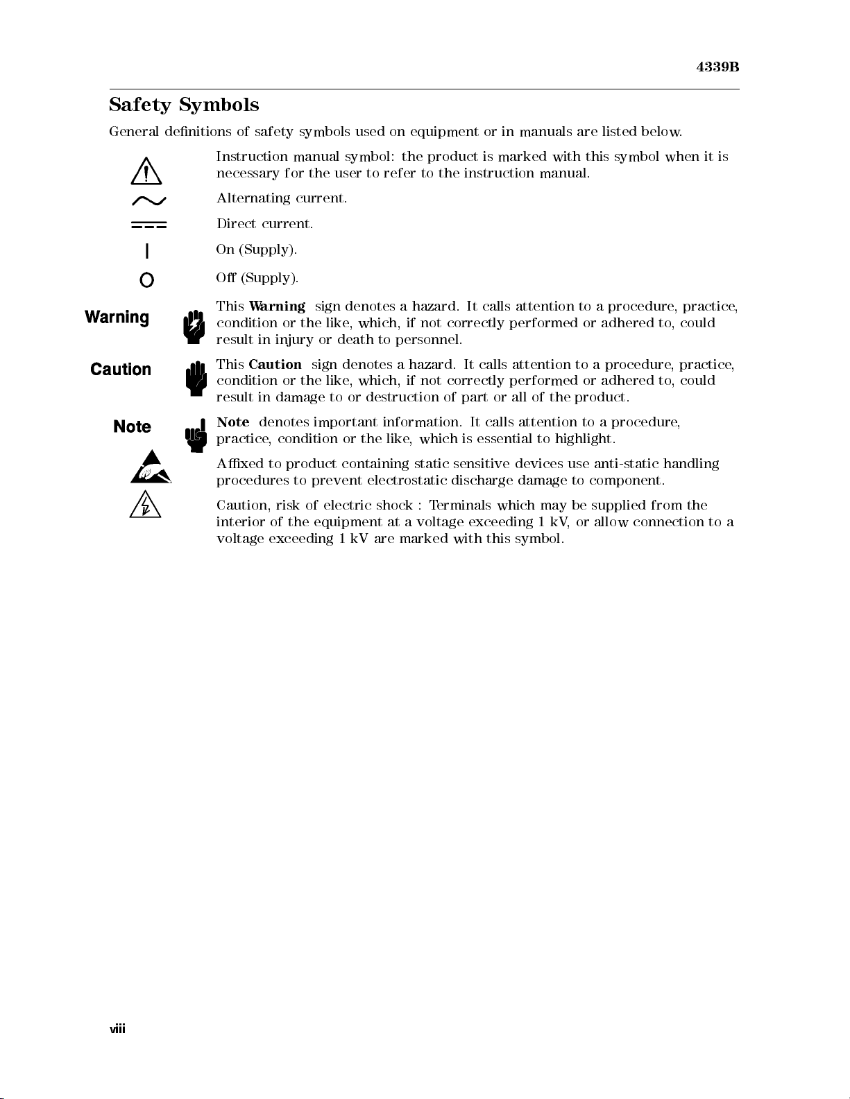
Safety Symbols
4339B
General
denitions
Instruction
necessary
Alternating
Direct
On
O
This
condition
result
This
condition
result
Note
practice
Axed
procedures
Caution,
interior
voltage
of
safety
symbols used
manual
for
the
current.
current.
(Supply).
(Supply).
W
arning
in
Caution
in
or
the
injury
sign
or
the
damage
sign
or
denotes important
, condition
to
product
to
prevent
risk
of
of
the
equipment
exceeding
symbol:
user
denotes
like
,
which,
death
denotes
like
,which,
to
or
or the
containing
electric
1
kV
on equipment
the
product is
to refer
to the
a
hazard. It
if not
to
personnel.
a
hazard.
if not
destruction
information.
like
,
which
static
electrostatic
shock
:
T
at
a
voltage
are
marked
or in
manuals are
marked with
instruction manual.
calls attention
correctly performed
It calls
correctly
of
part
It
is
sensitive
discharge
erminals
exceeding
with
attention to
performed
or
all of
calls
attention
essential
devices
damage
which
this
symbol.
to
may
1
this symbol
to a
or adhered
a procedure
or
the
product.
to
highlight.
use
anti-static
to
component.
be
supplied
kV
,
or
allow
listed below
when it
procedure
to
adhered
a
procedure
to
handling
from
connection
.
is
,
practice
,
could
, practice
,
could
,
the
to
,
,
a
viii

4339B
Herstellerbescheinigung
GERSCHEMISSION
LpA
<
70
dB
am
Arbeitsplatz
normaler
nach
DIN
Betrieb
45635
T
.19
Manufacturer's Declaration
A
COUSTIC
LpA
<
NOISE
70 dB
EMISSION
operator position
normal
per
operation
ISO
7779
ix
4339B
Contents of
Chapter
Provides
4339B
Chapter
Shows
learn
Chapter
Describes
the
functions
Chapter
Shows how
the
should
how
about
1
product overview
read
2
to
operate
operations
3
all
functions
of
4
to remotely
the procedures
Chapter
5
this Manual
this
chapter
the
4339B
using
of this
the front
and rear
operate
for remotely
operating the
and basic
measurement procedure
rst.
from
its
front
the
front
panel
instrument. Refer
panel keys
the
4339B
.
4339B
panel.
keys
and
Refer
.
to this
terminals
to
this
via
the
Refer
chapter
chapter
GPIB
to
. First
this
when
time users
chapter
you
when
wish
to
of the
you
learn
wish
about
to
.
when
you
wish
to
learn
about
.
Contains
chapter
system,
Chapter
Provides
Chapter
Provides
complete information
when
you
wish
to
learn
and
data
transmission
6
a
measurement example
7
information for
eective operations
on
remotely
about
format.
using the
the
Chapter 8
Provides
specications
,
reference
data,
and
Chapter 9
Describes how to verify the specications
operating
GPIB
4339B
.
other
.
the
commands
.
general
4339B
,
status
via
the
reporting
information.
GPIB
.
mechanism,
Refer
to
this
trigger
x

4339B
Appendix
Contains
information
printed.
Appendix
Contains
handler
information which
interface,
Appendix
The
summary
current
limit),
A
B
C
of
operations
or
N.C.
on
using
read this
(No-Contact).
the
4339B
is required
appendix
when
the
s
for
and
4339B
which
using
set
the
detects
were
manufactured
the
handler
handler
O
VLD
interface
interface
(Overload),
before this
.
Before
input/output
Over-Current
manual was
using
the
signal.
(exceeding
xi


Contents
1.
Getting
Introduction
Overview
F
A
Front
Display
Rear
Initial
Providing
Instruction for
P
ower
Preparation
P
Started
eatures
ccessories
P
P
anel
Inspection
Cable
ower
Fuse
.
.
.
.
.
.
.
.
.
.
.
.
.
A
vailable
anel
.
.
.
.
.
.
.
.
.
.
.
.
.
clearance
.
for
Requirements
.
to
Cleaning .
.
.
.
Use
.
.
.
.
.
.
.
.
.
.
.
.
.
.
.
.
.
.
.
.
.
.
.
.
.
.
dissipate
.
.
.
.
.
.
.
.
.
..
.
.
.
.
.
.
.
.
.
.
.
.
.
.
.
.
.
.
.
.
.
.
.
.
..
.
.
.
.
.
.
.
.
.
.
.
.
.
.
.
.
heat
.
.
.
.
.
.
.
.
.
.
.
.
.
.
.
.
.
.
.
.
.
.
.
.
.
.
.
..
.
.
..
.
.
.
at
installation
.
.
.
.
..
.
.
.
.
.
.
.
.
.
.
.
.
..
.
..
.
.
.
.
..
..
.
.
.
.
..
.
.
.
.
.
.
..
..
..
.
.
.
..
..
..
.
..
.
.
..
..
.
.
.
.
..
..
..
.
.
..
.
.
..
site
.
.
.
.
..
.
..
.
.
..
..
..
..
..
.
.
.
.
.
.
.
.
.
.
..
..
.
.
..
.
.
..
.
.
.
.
.
.
.
.
.
.
.
.
.
..
.
.
.
.
.
.
.
.
.
..
.
.
.
.
.
.
.
.
.
.
.
.
.
.
.
.
.
.
.
.
.
.
.
.
.
.
.
.
.
.
.
.
.
.
.
.
.
.
..
.
.
.
.
.
.
.
.
.
.
.
.
.
.
.
.
.
.
..
.
.
.
.
.
.
.
.
.
.
.
.
.
.
.
.
.
.
.
.
.
.
.
.
.
.
.
.
.
.
.
.
.
..
.
.
.
.
.
..
.
.
.
1-1
.
1-2
.
1-2
.
1-3
.
1-4
.
1-6
.
1-7
.
1-8
.
1-8
.
1-9
.
1-10
.
1-12
.
1-12
. 1-12
Turning
P
ower-On
Using
Front
Direct
T
Selection
V
Basic
Floating DUT Measurement . . . . . . . . . .
Grounded DUT Measurement . . . . . . . . . .
Resetting 4339B . . . . . . . . . . . . . . . . . . . . .
Performing Calibration . . . . . . . . . . . . . . . . . . . . .
Setting T
Selecting Measurement P
Selecting Measurement Range ........................ 1-23
Auto Range mode ...... ...... ...... ...... ..... 1-23
Hold Range mode ............................. 1-23
Execution
oggle
Type
alue
Setup
V
alue Setup
V
alue Setup
V
alue Setup
V
alue Change
Operation .
Connecting
est Voltage ....................
Performing OPEN Correction
Changing the Range in Hold Range mode ................. 1-23
ON
the
Self
T
est
P
anel
Keys
Type
Keys
Type
Keys
Type
Keys
Using Numeric
Using Maximum
Using Down
Using Back
..
T
est
4339B
.
Keys
.
.
.
..
Fixture
arameter ...... ..... ...
.
.
.
.
.
.
.
.
.
.
.
.
.
.
.
and Up
Space Key
..
..
.
.
.
.
.
.
.
.
.
..
.
.
.
.
.
.
.
.
.
..
.
.
.
.
.
..
.
.
.
.
.
.
.
.
.
.
.
.
.
.
.
..
.
.
.
.
.
.
..
..
.
.
.
.
.
.
.
.
.
.
.
..
..
.
.
.
.
.
.
.
.
..
..
.
.
.
.
.
.
.
.
Keys .
and Minimum
.
.
.
.
.
.
.
.
.
.
Keys
.
.
.
Arrow
.
.
.
.
...... ...... ...... ....
Keys
..
.
.
.
.
.
.
.
.
.
.
.
.
.
.
.
.
.
.
.
.
.
.
.
.
.
.
.
.
.
..
...... ...... ...
..............
.
.
.
.
.
.
.
.
.
.
.
.
.
.
.
.
.
.
.
.
.
.
.
.
.
.
.
.
.
.
.
.
.
.
.
.
.
.
.
.
.
.
.
.
.
.
.
.
.
.
.
.
.
.
.
.
.
.
.
.
.
.
.
.
.
.
.
.
.
.
.
..
.
.
.
.
.
.
.
.
.
.
.
.
.
.
.
.
.
.
.
.
.
.
.
.
.
.
.
.
.
.
.
..
..
..
.
.
.
.
.
.
.
.
...... ....
...... .
.........
........
.
.
.
.
.
.
.
.
.
.
.
.
.
.
. 1-16
.
.
.
.
.
.
. 1-18
.
.
1-13
1-14
1-15
1-15
1-15
1-15
1-16
1-17
1-17
1-17
1-19
1-19
1-19
1-20
1-20
1-21
1-22
1-23
Applying Test Voltage........ ...... ...... ...... 1-24
Contents-1

2.
Operating
Introduction
Measurement
Selecting
Setting
Setting
Setting
Making
Triggering
Using
Displaying
Using
Turning
the
the
the
the
Entering
Setting
a
Measurement
the
Setting
Selecting
the
Selecting
Setting
Setting
OFF
T
est
V
oltage
4339B
.
.
.
.
.
.
.
Conguration
the
Measurement
A
veraging
Trigger
P
arameters
Thickness
the
Electrode
a
Measurement
Comparator
Deviation
the
Reference
the
Measurement
the Measurement
the Measurement
Time
Display
Rate
Delay
for
of
.
Function
Data
Deviation
Function
the
Size
.
Value
Sequence
.
.
.
.
.
..
..
..
.
.
.
..
Time
Mode
.
.
.
.
..
Time
Display
.
.
.
Resistivity
DUT
..
.
..
..
..
..
..
.
.
.
.
..
.
.
.
.
.
.
.
..
..
..
Mode
Function
Sequence Mode
Sequence Mode
.
.
.
.
..
..
..
..
..
..
..
..
.
.
.
.
..
..
..
..
.
..
..
..
Measurement
..
..
..
..
..
.
..
.
.
.
.
..
..
.
..
..
..
..
..
.
.
.
.
.
.
..
..
.
.
.
.
.
.
P
arameters
.
.
.
.
.
.
..
..
..
..
.
..
.
.
.
.
.
.
.
.
.
.
.
.
.
.
.
.
.
.
.
.
.
.
.
..
.
..
..
.
.
.
.
..
.
.
.
.
.
.
.
.
.
.
.
.
.
.
.
.
..
.
.
.
.
.
..
.
..
..
.
.
.
.
..
.
.
.
.
.
.
.
.
.
.
.
.
.
.
.
.
.
.
..
.
.
.
.
.
..
.
.
.
.
.
.
.
.
..
.
.
.
.
.
.
.
.
.
.
.
.
.
.
.
.
.
.
..
.
.
.
.
.
..
.
.
.
.
.
.
.
.
.
.
..
.
.
.
.
.
.
.
.
.
.
.
.
.
.
.
.
.
.
.
.
.
.
..
.
.
.
.
.
.
.
.
.
.
.
.
.
.
.
.
.
.
.
.
.
.
.
.
.
.
.
.
.
.
.
.
.
.
.
..
.
.
.
.
.
.
.
.
.
.
.
.
.
.
.
.
.
.
.
. 2-5
.
.
.
.
.
.
.
.
.
.
.
.
.
.
.
.
.
.
1-24
2-1
2-2
2-2
2-2
2-2
2-3
2-3
2-3
2-5
2-5
2-7
2-7
2-8
2-9
2-9
2-9
2-10
Starting
Aborting
Setting
Setting
Setting
Setting
Setting
Changing
Saving
Locking
Selecting
Setting
Printing
Setting
T
esting
Performing a Self-T
Testing the Front P
If Y
If the Display is Blank and the 4339B Appears
If an Error Message is Displayed
If the 4339B does not A
If the Indicated V
If Y
Contact
Reading
Reading
Current
Current
Beeper
Display
and Recalling
Out the
Local Mode
the
Measurement
the
the
4339B
ou Have a Problem . .
ou Find Y
Measurement
Measurement
Check
the
Limit
Data of
the
Capacitance
Limit
Monitor
Mode
Measurement
GPIB
Oset-Error
ourself Lost When Operating the 4339B . . . . . . . . . .
.
Mode
and
Instrument
Front
P
.
A
ddress
Data
.
.
.
est ..................
anel Key's Functionality
ccept Any Key Input
alue is not Stable
Sequence
Sequence
.
.
.
Contact
Data
.
.
..
.
.
.
..
Display
Settings
anel
Keys
.
.
.
.
.
.
.
Canceling
.
.
.
.........................
.
.
at DUT
.
..
..
Display
Settings
.
.
.
.
.
.
..
.
.
.
.
.
Check
.
.
.
.
.
.
.
.
.
F
ormat
.
.
.
.
.
.
.
.
.
.
.
Function
.
.
...
...
.
.
.
.
..
..
.
.
.
.
.
.
.
.
.
.
.
.
.
.
..
..
.
.
.
.
.
.
.
.
.
.
..
.
.
.
.
.
.
.
.
.
.
.
.
.
.
.
.
Function
Measurement
.
.
.
.
.
.
.
.
.
.
.
.
.
.
.
Mode
.
.
.
.
.
.
.
.
.
.
.
.
.
.
.
..
.
.
.
.
.
.
.
.
.
...... ..... ....
Dead.............
...................
................
...... ...... ......
.
.
.
.
.
.
.
.
.
.
.
.
.
.
.
.
..
.
..
.
.
.
.
.
.
.
.
.
.
.
.
.
.
.
.
.
.
.
.
.
.
..
..
.
.
.
.
.
.
.
.
.
.
.
.
.
.
.
.
.
.
.
.
.
.
.
.
.
.
.
.
.
.
.
.
.
.
.
.
.
.
.
.
.
.
.
.
.
.
.
.
.
.
.
.
.
.
.
.
.
.
.
.
.
.
.
.
..
.
.
..
..
..
..
.
.
.
.
..
..
.
.
.
..
..
..
.
..
.
.
.
.........
.
.
.
.
.
.
.
.
.
.
.
.
.
.
..
.
.
.
..
..
.
.
.
.
.
..
.
.
...
.
.
.
.
.
.
..
.
.
.
..
.
..
.
2-11
.
2-11
.
2-12
.
2-13
.
2-13
.
2-14
.
2-14
. 2-14
. 2-16
.
2-17
. 2-18
2-18
.
2-18
.
2-19
.
2-19
2-19
.
2-20
2-20
2-21
. 2-22
2-22
2-22
2-22
2-22
2-22
Contents-2

3.
Function Reference
Introduction
Front
Panel
Display
LINE
Switch .
Interlock
..
.
.
.
.
.
.
.
.
..
.
.
.
.
.
.
.
Connector .
.
.
.
.
.
.
.
.
..
..
..
..
..
..
..
.
.
.
.
.
.
3-1
.
.
.
.
.
.
..
..
..
..
..
..
..
.
.
.
.
.
.
.
.
3-2
.
.
.
.
.
.
.
..
..
..
..
..
..
..
.
.
.
.
.
.
.
3-2
.
.
.
.
.
.
.
.
..
..
..
..
..
..
..
.
.
.
.
.
.
3-3
.
.
.
.
.
.
.
.
.
.
.
..
..
..
..
..
..
..
.
.
3-3
UNKNOWN
High
V
oltage
V
Output
V Output
Source V
Current Limit
Measurement Time
A
verage
Measurement
Single
Continuous
Program
Time
Measurement
Electrode
Show
Current
oltage key
key
Mode
Display
Setting
Monitor
Key
Indicator .
Key
Sequence
..
mode
Key
Function
P
arameter
Size
Key
Key
Key
T
erminals
Indicator
..
key
Mode Key
..
..
.
.
.
.
..
.
..
.
.
Key
.
.
.
.
.
..
.
.
..
..
.
.
..
..
.
.
.
.
.
.
.
.
.
.
..
.
.
..
..
.
..
.
.
.
.
..
.
.
.
.
.
.
.
.
.
.
..
..
.
.
.
..
.
.
.
.
.
.
.
.
..
.
.
.
.
.
.
.
.
.
.
.
.
..
..
.
.
.
.
..
.
.
.
.
.
.
.
.
.
.
.
.
.
.
.
.
.
.
.
.
.
.
.
.
.
.
.
.
.
.
.
.
.
.
.
.
.
..
.
.
.
.
.
.
.
.
.
.
.
.
..
.
.
.
.
.
.
.
.
.
.
.
.
.
.
.
.
.
.
..
.
.
.
.
.
.
.
.
.
.
.
.
..
.
.
.
.
.
.
.
.
.
.
.
.
.
.
.
.
.
.
.
.
.
.
.
.
.
.
.
.
.
.
.
.
..
.
.
.
.
.
.
.
.
.
.
.
.
.
.
.
.
..
.
.
.
.
.
.
.
.
.
.
.
.
.
.
.
.
.
.
.
.
.
.
.
.
.
.
..
.
.
.
.
.
..
.
.
.
.
.
..
.
.
.
.
.
.
.
.
.
.
.
.
.
.
.
.
.
.
.
.
.
..
.
.
.
..
.
.
.
.
..
.
.
.
.
.
.
.
.
.
.
..
.
.
.
.
..
.
.
.
.
.
.
..
..
.
.
.
.
..
.
.
.
.
.
.
.
.
.
.
..
.
.
.
.
.
.
.
.
.
.
.
.
..
.
.
.
.
.
.
.
.
. 3-5
.
.
.
. 3-5
.
.
.
.
..
.
. 3-6
.
.
.
.
.
.
.
.
.
.
.
3-4
3-4
3-4
3-5
3-5
3-5
3-6
3-6
3-7
3-8
3-8
3-8
3-10
3-10
A
uto/Hold
Range
Sequence
Local
Address
Trigger Mode Key ...... ..... .
Delay Key .............
Recall Key
Save Key .........................
Comparator
Left/Down and Right/Up Arrow Keys ............... 3-13
0, . . . , 9, .(point),0(minus) Keys ... ...... ... 3-13
Shift Key ......... ..... ...... ...... .... 3-13
Exponential Key ........................... 3-13
Range
Setup
Trigger
Abort
Key
Key
Key
Key
.
.
..
Key
Key
.
...... ...... ...... ......
Limit Keys .
.
.
.
.
.
.
.
.
.
..
..
.
.
.
.
.
.
.
..
..
..
.
.
.
.
.
.
.
.
.
.
.
..
..
.
.
.
.
.
.
.
.
.
.
.
.
..
..
..
..
..
..
.
.
.
..
.... ...... ...... ...... ..
..............
..............
....................
.
.
..
..
..
.
.
.
.
.
.
.
.
..
.
.
.
.
.
.
.
.
.
.
.
.
.
.
.
.
.
..
..
.
.
.
.
.
..
......
...
.
.
.
.
.
.
.
.
. 3-11
3-10
3-10
3-11
3-11
3-11
3-12
3-12
3-12
3-12
3-12
Contents-3

Back
Space Key
.
..
..
.
.
.
.
.
.
.
.
.
.
.
.
.
..
..
..
..
. 3-13
Enter
Key
Minimum
Maximum
Open
Key
Calibration
Comparator
Contact
Display
Key
Lock
Reset
Key
Conguration
Rear
P
anel
External
LINE
Fuse
LINE
V
oltage
P
ower
Cord
P
ower
Serial
Number
Handler
Specications
GPIB
Interface
Theory
of
Overall
Overall
Grounded
.
..
Key .
Key
Key
On/O
Check
Mode
Key
.
.
Trigger
Holder
Receptacle
Cord
Interface
Operation
Measurement
Block
and
Key
Key
Key
Key
.
.
..
.
.
.
Selector
.
.
.
Plate
.
.
.
.
.
.
Diagram
Ungrounded
.
.
.
.
.
.
.
.
.
.
.
.
.
.
.
.
.
.
.
.
.
.
.
.
.
.
.
.
.
.
.
.
.
.
.
.
.
.
.
Theory
.
.
.
.
.
..
.
.
.
.
.
.
.
.
.
.
.
.
.
.
.
.
.
..
.
.
.
.
.
.
..
.
.
.
.
.
.
.
.
.
.
.
.
.
.
.
.
.
.
.
.
.
.
.
.
.
.
.
.
.
.
.
.
DUT
Measurement
.
.
.
.
.
.
.
.
.
.
.
.
.
.
.
.
.
..
.
.
.
.
.
.
.
.
.
.
.
.
.
.
.
.
.
.
.
.
.
.
.
.
.
.
..
.
.
.
.
.
.
.
.
.
.
.
.
.
.
.
.
.
.
..
.
.
.
.
.
.
.
.
.
.
.
.
.
.
.
..
.
.
.
.
.
.
.
.
.
..
..
.
.
..
.
.
.
.
.
.
.
..
.
.
.
.
.
.
.
..
.
.
.
.
.
.
.
.
..
..
..
..
.
.
.
.
..
..
.
.
.
.
.
.
.
.
.
.
.
.
.
.
.
.
.
.
.
.
.
.
.
.
..
.
.
..
.
.
..
.
.
..
.
.
.
..
.
.
.
.
.
.
.
Conguration
..
.
.
..
..
..
.
.
.
..
..
..
.
.
.
.
.
.
.
.
..
.
..
.
.
..
.
.
.
.
.
.
.
.
.
.
.
.
.
.
..
..
..
..
..
.
..
..
..
.
.
.
.
.
.
.
.
.
.
..
..
.
..
..
.
.
.
.
.
.
.
.
.
.
.
.
.
.
..
..
..
..
..
..
..
.
.
.
.
.
.
.
.
.
.
.
.
..
..
..
.
.
.
.
.
.
.
.
.
.
.
.
.
.
.
.
.
..
..
..
..
.
..
..
.
.
.
.
.
.
.
.
.
.
.
.
.
.
..
.
.
.
.
.
.
.
.
.
.
.
.
.
.
.
.
.
.
..
..
..
..
.
.
.
.
..
.
.
.
.
.
.
.
.
.
.
.
.
.
.
.
.
.
.
.
.
.
.
.
.
.
.
.
.
.
.
.
.
.
.
..
..
..
..
.
.
.
.
.
.
.
.
.
.
.
.
.
.
.
..
.
.
.
.
.
.
.
.
.
.
.
.
.
.
.
.
.
.
.
.
.
.
.
.
.
.
.
..
.
.
.
.
.
.
.
.
.
.
.
.
.
.
.
.
.
.
.
.
.
.
.
.
.
.
.
.
.
.
.
.
.
.
.
.
.
.
.
.
.
.
.
.
.
3-13
3-13
3-13
3-14
3-14
3-14
3-15
3-16
3-16
3-17
3-18
3-20
3-20
3-21
3-21
3-21
3-21
3-21
3-22
3-22
3-25
3-26
3-26
3-27
3-28
4.
Remote
Introduction .
Getting Started
Contents-4
Operation
..
..
.
.
.
.
.
.
.
.
.
.
.
.
.
.
.
.
.
.
.
..
..
..
.
.
.
..
..
.
.
.
.
.
.
.
.
.
.
.
.
.
.
.
.
.
.
.
..
..
..
.
.
Input/Output Statements
Reading the
Sending a
Returning
Query Commands
Getting Data from the
To Control the 4339B
To Set Up the 4339B
To Reset the 4339B
To Set the P
To Select the Measurement P
To Set the T
ToSettheCurrentLimit ....... ...... ..... ...... . 4-6
To Select Measurement Time Mode .. ...... ...... ...... 4-6
ToPerform Calibration . . . . . . . . . . . . . . . . . . . . . . . . . . 4-6
ToPerform OPEN Correction . . . . . . . . . . . . . . . . . . . . . . . 4-7
To Select the Measurement Range . . . . . . . . . . . . . . . . . . . . . 4-7
GPIB A
Remote Command
to
Local Mode
ower LINE Frequency
est V
oltage . . . . . . . . . .
To Apply the Test Voltage . . . . . . . . . . . . . . . . . . . . . . 4-6
..
..
..
.
.
.
.
.
.
.
.
.
.
.
.
.
.
.
.
ddress .
.
.........................
4339B . . . . . . . . . . . . . . . . . . . . . . . .
from an External Computer
...... ...... ...... ...... .
.
..
.
.
.
.
.
.
.
.
.
.
.
.
.
.
.
.
.
..
..
..
..
.
.
.
.
.
.
.
.
.
.
.
.
.
..
.
.
.
.
.
.
.
.
.
.
..
.
.
.
.
.
.
.
.
.
.
..............
.........................
...... ..
arameter . . . . . . . . . .
................
............
.........
.
..
..
..
.
..
...
...
. 4-2
. 4-2
. 4-2
.
. 4-5
4-1
4-2
4-2
4-3
4-3
4-4
4-5
4-5
4-5
4-5

T
o Set
T
o Set
T
o Set
T
o Set
T
o Lock
T
o Check
T
o
Use
T
o
Display
T
o
Set
T
o
T
o
Get
T
o
Save
T
o
Trigger
W
aiting
Sample
Reading
Reading
Reading
Data
T
o
Retrieve
T
o
Use
Other
F
T
o
T
est
T
o
Read
T
o
Report
the A
Trigger
the
Beeper
Out
Contact
the
Comparator
a
the
Oset-Error
W
ait
Until
the
Current
and
a
Measurement
F
or
Completion
program
Out
Measured
out
out
Retrieval
Data
Data
T
o
P
erform
eatures
the
4339B
the
the
veraging
Delay
P
arameters
Mode
the
Front
Integrity
Deviation
Previously
Instrument
Recall
measured
measured
Buer
Error
Instrument
.
.
Result
.
.
.
Eciently
.
a
Measurement
.
.
.
.
Queue
Instrument's
Rate
Time
Function
Measurement
Canceling
Of
.
result
result
.
.
.
.
.
.
for
Resistivity
.
.
.
.
P
anel
Keys
at
Sent
Settings
Settings
.
.
.
Measurement
.
.
.
.
.
.
using
using
.
.
.
.
.
.
.
.
..
.
.
.
.
.
.
.
.
.
.
.
Status
.
.
.
.
.
.
.
.
.
.
Measurements
.
.
.
.
.
.
.
the
T
est
Fixture
.
.
.
.
.
.
Function
Commands
.
.
.
.
..
..
(detecting
.
.
.
..
.
.
.
.
.
*TRG
:FETC?
.
.
.
.
.
.
.
.
.
.
..
..
.
Sequence
.
.
..
..
.
..
..
.
.
.
.
.
.
..
.
.
.
.
.
.
..
..
..
.
.
.
.
.
.
.
.
.
.
.
.
.
are
Completed
.
.
.
.
.
.
..
..
..
..
.
..
command
command
..
.
.
.
.
.
.
.
.
.
.
..
.
.
.
.
.
.
..
.
.
.
.
.
..
..
..
..
.
.
..
..
..
..
..
.
.
.
.
..
.
..
..
.
.
..
.
.
.
.
.
.
..
..
..
..
.
.
.
completion
.
.
.
.
..
..
.
.
.
.
.
.
.
.
.
.
.
.
..
.
.
.
.
.
.
.
..
..
.
.
.
.
.
.
.
.
.
.
.
.
.
.
.
.
.
.
.
.
..
..
..
..
.
.
.
..
..
..
..
..
..
..
..
..
..
..
..
..
.
.
.
.
..
..
..
.
.
.
.
.
.
of
measurement)
.
.
.
.
.
.
.
.
.
.
..
..
..
.
.
.
.
.
.
.
.
.
.
.
.
..
.
.
.
.
.
.
.
.
.
.
.
.
.
.
.
.
.
..
..
..
..
..
..
.
.
..
..
..
..
.
.
.
.
.
.
.
.
..
.
.
.
.
.
.
.
.
.
.
.
.
.
.
.
.
.
.
..
..
..
.
.
..
..
.
.
.
.
..
..
.
.
.
.
.
.
.
.
.
.
..
.
.
.
.
.
.
.
.
.
.
.
.
.
.
.
.
.
.
.
.
.
. 4-8
.
.
.
. 4-8
.
.
.
.
.
.
..
.
.
.
.
.
.
.
.
.
.
.
.
.
.
.
.
.
.
.
.
.
.
.
.
.
.
.
.
.
.
4-7
4-7
4-8
4-8
4-9
4-9
4-9
4-9
4-10
4-10
4-11
4-12
4-13
4-14
4-15
4-19
4-23
4-24
4-24
4-25
4-26
4-26
4-26
4-26
Sample
If Y
ou
Have
If
the
5.
GPIB
Reference
Introduction
GPIB
Commands
Common
Subsystem
Sybsystem
Program
Command
Case ....................
Program Message T
Common Command Syntax . . . . . . . . . . . . . . . . . . . .
Subsystem Command Syntax . . . . . . . . . . . . . . . . . . . . .
Parameters .... ...... ...... ......
Parameter Types . . . . . .
Multiple Messages
Query and Response Message Syntax
Command Reference . . . . . . . . . . . . . . . . . . . . . . . . . . . . . 5-6
Notations ................................. 5-6
ABORt Command .............................. 5-7
:ABORt .................................. 5-7
ARMSubsystem ....... ...... ..... ...... ...... . 5-8
:ARM[:SEQuence1][:LAYer]:DELay<numeric value>[MSjS] ......... 5-9
:ARM[:SEQuence1][:LAYer]:SOURcefBUSjEXTernaljMANualjIMMediateg... 5-9
Program
a
Problem
4339B
Hangs
.
.
Commands
Commands
Command
Message
Abbreviations
.
.
.
.
.
.
.
.
.
.
.
.
.
.
.
.
.
.
.
.
.
.
.
.
.
.
.
.
.
.
.
.
.
.
.
.
Up
When
Y
ou
Send
the
ABORt
.
.
.
.
.
.
.
.
.
.
.
.
..
.
.
.
.
.
.
.
.
.
.
.
.
.
.
.
.
.
.
.
.
.
..
..
.
.
.
.
.
.
.
..
..
Tree
Syntax
erminator .... ..... ...... ...
........
.
.
.
.
.
.
..
.
.
.
.
..
..
..
.
.
.
.
..
.
.
.
...... ...... ...... .....
.....................
......
Command
..
..
..
.
.
..
..
..
..
.
.
.
.
.
..
..
.
.
..
..
..
.
..
..
..
.
.
.
.
.
.
.
...... ...... ...
...... ...... ..
.
.
..
.
.
.
.
.
.
..
.
.
.
.
.
.
.
.
.
.
.
..
..
.
.
.
.
.
.
.
.
.
.
.
.
.
.
.
.
.
.
.
.
.
.
.
.
.
.
.
.
.
.
.
.
.
.
.
.
.
.
.
.
.
.
.
.
.
.
.
.
.
.
.
.
.
.
.
..
.
.
.
.
.
.
......
.....
...
..........
.
4-28
.
4-30
4-30
.
5-1
.
5-1
.
5-1
.
5-1
.
5-1
.
5-2
.
5-2
5-3
5-3
5-3
5-3
5-3
5-3
5-4
5-5
Contents-5

CALCulate
:CALCulate1:FORMat
:CALCulate1:LIMit:BEEP
:CALCulate1:LIMit:BEEP
:CALCulate1:LIMit:CLEar
:CALCulate1:LIMit:F
:CALCulate1:LIMit:LOW
:CALCulate1:LIMit:LOW
:CALCulate1:LIMit:ST
:CALCulate1:LIMit:UPP
:CALCulate1:LIMit:UPP
:CALCulate1:MA
:CALCulate1:MA
:CALCulate1:MA
:CALCulate1:P
:CALCulate1:RESistivity:EARea
:CALCulate1:RESistivity:EPERimeter
:CALCulate1:RESistivity:GLENgth
:CALCulate1:RESistivity:STHickness
:CALCulate2:MA
:CALCulate3:FORMat
:CALCulate3:MA
:CALCulate3:DIRECtion
:CALCulate3:BEEP
CALibration
:CALibration[:ALL]?
:CALibration:A
D
A
T
A
:D
A
:D
A
:D
AT
:D
AT
:D
AT
:D
A
:D
A
DISPlay
:DISPlay[:WINDow][:ST
:DISPlay[:WINDow]:TEXT1:DIGit
:DISPlay[:WINDow]:TEXT1:P
:DISPlay[:WINDow]:TEXT1:PREFix
:DISPlay[:WINDow]:TEXT2:PAGEf1j2j3
FETCh? Query
:FETCh? ...........
FORMat Subsystem
:FORMat[:DATA]fASCiijREAL[,64]
INITiate Subsystem .....................
:INITiate[:IMMediate] .......... ...... ...... .
:INITiate:CONTinuousfONjOFFj1j0g...............
Subsystem .
TH:EXPRession:CA
TH:EXPRession:NAME
TH:ST
A
TH?
TH:ST
TH:ST
Subsystem
UTO
Subsystem
T
A[:D
A
T
A[:D
A
A[:D
A
A[:D
A
A:FEED
T
A:FEED:CONTrol
T
A:POINts
Subsystem
.
.
T
A]
REF
T
A]?
DBUF
T
A]?
IMON
T
A]?
TMON
DBUF
DBUF
.
..... ....
..
.
.
.
.
.
.
f
REAL
AIL? .
er[:D
er:ST
A
T
er[:D
er:ST
A
T
.
.
A
T
f
SEC
A
T
er
f
ON
.
.
.
f
ON
.
.
.
,
<
numeric
.
.
.
,
<
data
DBUF
,
<
numeric
.
.
.
A
...........
j
SRESistivity
er:CONDition
er[:STA
e
e
e
e
f
j
OFF
T
..
.
A
A
f
ON
A
A
f
ON
.
.
f
ON
j
TPCNT
f
ON
UP
j
DOWN
j
OFF
..
.
.
j
.
.
.
.
.
.
.
.
handle
,
f
.
.
e]
f
ON
A
T
e]
.
.
.
.
.
T
A]
<
T
e
f
j
OFF
T
A]
<
T
e
f
ON
j
OFF
.
.
.
<
numeric
j
OFF
j
OFF
j
1
j
0
g
..
.
..
.
1
j
0
g
.
.
.
.
value
.
.
.
.
.
.
.
.
.
>
AL
W
value
.
.
.
j
OFF
f
GE
f
...... ...... ...... ....
......................
f
f
ON
.
.
.
.
numeric
ON
j
j
1
numeric
j
T
alog?
j
.
.
<
<
numeric
<
numeric
j
1
j
0
g
.
.
j
1
j
0
g
.
.
.
.
.
.
.
.
.
.
.
>
.
.
.
.
.
.
.
.
.
ays
>
.
.
j
1
j
3
j
4
j
5
1
j
2
g
f
ON
g
.
.
.
.
.
.
.
..
..
..
..
j
VRESistivity
P
ASS
j
F
AIL
j
OFF
j
1
j
0
.
.
.
.
.
.
.
.
.
.
.
..
value
>
OFF
j
1
j
0
g
j
0
g
.
..
value
>
OFF
j
1
j
0
g
.
.
.
.
.
f
DEV
j
PCNT
1
j
0
g
..
..
..
..
..
value
>
.
.
.
.
.
.
.
.
.
value
.
..
..
..
.
.
.
.
.
.
.
.
.
.
.
.
.
.
.
.
.
.
.
.
.
.
er
.
.
.
..
.
.
.
.
..
j
1
j
0
value
value
.
.
.
.
.
.
.
.
.
.
.
.
g
.
..
.
..
g
>
.
..
.
.
.
.
.
.
.
.
.
.
.
.
..
.
..
.
.
numeric
g
.
.
..
g
.
.
.
.
.
.
.
.
.
.
.
.
.
.
.
.
.
.
j
NEV
.
.
0
g
g
..
j
OFF
j
4j5j6g...... ...... ....
...... ...... ......
.............
g
g
.
..
..
..
.
g
.
.
>
>
.
.
.
.
.
.
.
..
.
.
.
.
.
.
..
.
..
.
.
.
..
..
..
.
.
..
..
.
.
..
..
.
.
.
.
.
.
.
.
.
.
.
.
.
.
.
.
.
.
.
.
.
.
.
.
.
.
.
.
.
.
.
..
.
..
.
..
.
.
..
.
.
..
..
.
.
..
.
.
g
.
.
.
.
.
.
.
..
..
..
..
..
..
..
..
..
..
.
.
.
.
.
..
..
..
.
.
.
.
.
.
.
..
..
..
..
..
.
.
..
..
.
.
.
.
.
.
.
.
.
.
.
.
.
.
.
.
.
.
.
.
.
.
.
.
.
.
.
.
.
.
.
.
.
.
.
.
.
.
.
.
.
.
.
.
.
.
.
.
.
.
.
.
.
.
.
.
.
.
.
.
.
.
.
.
.
.
.
.
.
.
.
.
.
.
.
.
.
.
.
.
.
.
.
.
..
.
.
..
.
.
.
.
.
.
.
..
..
.
.
.
.
.
.
.
.
.
.
.
..
.
.
..
..
..
.
.
.
.
.
.
.
.
..
......
...... ..
..
.
.
..
..
..
..
..
..
.
.
.
.
.
.
.
.
.
.
.
.
.
.
.
.
.
..
.
.
.
.
.
.
.
.
..
.
.
.
.
..
.
.
.
.
.
.
.
.
.
.
.
.
.
.
.
.
..
.
.
.
.
.
.
.
.
..
.
.
.
.
.
.
.
.
.
.
.
.
.
.
.
.
.
.
.
.
..
..
.
.
.
.
.
.
..
.
.
.
.
.
....
...
.
..
..
..
..
.
.
.
.
.
.
..
.
.
.
..
.
.
.
.
.
..
.
.
.
.
.
.
.
.
.
.
.
.
.
.
5-10
. 5-11
. 5-11
5-11
5-11
5-12
.
5-12
.
5-12
.
5-12
.
5-12
.
5-12
.
5-13
5-13
.
5-13
.
5-13
. 5-13
. 5-13
5-14
.
5-14
.
5-14
.
5-14
.
5-14
.
5-14
5-15
. 5-16
.
5-16
.
5-16
.
5-17
.
5-17
.
5-17
.
5-18
.
5-18
.
5-18
.
5-18
. 5-18
.
5-19
.
5-19
.
5-19
.
5-19
.
5-19
5-20
5-21
5-21
5-22
5-22
5-23
5-23
5-23
SENSe Subsystem .............................. 5-25
Contents-6
OUTPutSubsystem........................... 5-24
:OUTPut[:STATe]fONjOFFj1j0g...... ...... ...... .. 5-24
[:SENSe]:AVERage:COUNt<numeric value>................ 5-25
[:SENSe]:AVERage[:STATe]fONjOFFj1j0g................ 5-25
[:SENSe]:CONTact:DATA?.......................... 5-26

[:SENSe]:CONT
[:SENSe]:CONT
[:SENSe]:CONT
[:SENSe]:CORRection:COLLect[:A
[:SENSe]:CORRection:D
[:SENSe]:CORRection[:ST
[:SENSe]:CURRent:APERture
[:SENSe]:CURRent:RANGe:A
[:SENSe]:CURRent:RANGe[:UPP
[:SENSe]:FUNCtion
SOURce
:SOURce:CURRent:LIMit[:AMPLitude]
:SOURce:V
ST
A
:ST
:ST
:ST
:ST
:ST
:ST
:ST
SYST
:SYST
:SYST
:SYST
:SYST
:SYST
:SYST
:SYST
TRIGger
:TRIGger[:SEQuence1]:COUNt
:TRIGger[:SEQuence1]:DELay
:TRIGger[:SEQuence1][:IMMediate]
:TRIGger[:SEQuence1]:SOURce
:TRIGger[:SEQuence1]:TIMer
Common
3
3
3
3
3
3
3
3
3
3
3
3
Subsystem
Tus
Subsystem
A
Tus:OPERation:CONDition?
A
Tus:OPERation:ENABle
A
Tus:OPERation[:EVENt]?
A
Tus:PRESet
A
Tus:QUEStionable:CONDition?
A
Tus:QUEStionable:ENABle
A
Tus:QUEStionable[:EVENt]?
em
Subsystem
em:BEEP
em:BEEP
em:ERRor?
em:KLOCk
em:LFRequency
em:PRESet
em:VERSion?
Subsystem
Commands
CLS
.
ESE
<
numeric
ESE?
.
ESR?
.
IDN? . . . . . . . .
LRN? .... .....
OPC .... ......
RCL<numeric
RST ...... ...... ...... ..
SAV<numeric
SRE<numeric
STB? . . . . . . . . . . . . . . . . . . . . . . .
act:LIMit? .
act:OFFSet
act:VERify
OL
T
age[:LEV
er[:IMMediate]
er:ST
.
.
.
.
.
.
.
..
.
.
..
..
.
.
.
.
.
.
.
value
<
numeric
f
ON
j
OFF
CQuire] OFFset
AT
A?
f
OFFSet
AT
e]
f
ON
j
OFF
<
numeric
UTO
f
ON
er]
<
<
sensor
.
.
.
.
.
.
.
.
.
.
.
AT
e
.
..
f
ON
j
<
.
.
.
.
.
.
.
.
.
.
.
.
value
..
.
.
.
value>...... .....
value>...... ...... ...... ...
value>......................
function
.
.
.
.
.
.
.
el][:IMMediate][:AMPLitude]
.
.
.
.
.
..
.
.
<
numeric
.
.
.
.
.
.
.
.
..
..
.
<
numeric
.
.
.
.
.
..
..
..
..
f
ON
j
OFF
j
..
.
.
.
.
.
OFF
j
1
j
0
g
numeric
.
.
.
.
.
.
.
.
.
.
>
.
..
.
.
...... ...... ...... ...... .
value
.
.
.
.
.
.
.
.
.
.
.
.
.
.
.
<
numeric
<
numeric
..
f
BUS
j
<
numeric
.
.
.
.
.
.
.
.
.
..
.
.
.
.
.
..
..
..
.
.
.
.
.
.........................
...... ...... ...... ...... .
>
j
1
j
0
j
SCAP
j
1
value
j
OFF
numeric
>
.
.
.
.
.
<
numeric
..
..
.
.
.
value
.
.
.
.
.
.
.
.
value
.
.
.
..
..
.
.
.
1
j
0
g
.
.
.
.
.
.
>
.
.
.
.
.
.
.
.
.
.
value
value
.
.
EXT
ernal
value
.
.
.
..
.
.
.
.
.
.
..
g
acitance
j
0
j
.
..
.
>
.
.
.
.
.
.
.
.
.
.
.
.
.
>
.
..
.
.
.
.
.
.
.
.
.
..
..
..
..
.
.
.
.
.
.
.
.
.
.
.
.
..
.
.
.
..
..
..
..
..
.
.
.
.
.
.
.
.
.
.
.
g
.
.
.
.
..
..
g
.
..
..
..
..
..
>
[MS
j
S]
.
.
.
.
.
.
.
.
.
1
j
0
g
.
.
.
..
..
..
value
>
[P
A
j
NA
j
U
A
j
MA
j
A]
.
.
.
.
.
.
.
.
.
.
..
..
..
..
..
.
.
.
.
.
.
value
>
[MA
j
A]
.
.
.
.
value
>
[V
j
<
numeric
.
.
.
.
.
.
.
.
.
.
.
.
.
..
..
..
.
.
.
.
.
.
.
.
.
.
.
..
..
..
.
.
.
.
.
.
.
.
.
.
.
.
.
.
.
.
.
.
.
.
..
.
>
.
.
.
.
.
.
.
.
..
..
..
.
.
.
.
.
.
.
.
.
.
.
.
.
.
.
.
.
.
.
.
.
.
.
.
.
.
.
.
.
.
.
.
.
.
.
.
.
.
.
.
.
.
.
.
.
.
.
.
.
.
.
.
.
.
.
..
.
.
.
.
.
.
.
.
.
.
.
.
.
.
..
.
.
.
.
.
.
.
.
.
.
..
.
.
.
.
.
.
.
.
.
..
>
.
.
.
.
.
.
.
.
>
[MS
j
S]
.
.
.
.
.
.
.
.
.
.
.
.
.
.
.
.
j
INT
ernal
j
MANual
[MS
j
S]
.
.
.
..
..
..
..
.
.
.
.
.
.
.
..
.
.
.
.
.
.
.
.
.
.
.
.
...............
...... ...... ...
...... ......
.
.
.
.
.
..
.
.
.
.
j
TIMer
.
.
.
.
.
.
..
.
.
.
..
KV]
.
.
.
.
.
.
.
..
.
.
.
.
.
.
.
.
.
.
.
.
.
.
.
.
.
.
.
.
.
.
.
..
.
.
..
.
.
.
.
.
.
.
.
.
.
.
.
.
.
.
.
.
.
.
.
.
.
g
..
.
.
.
.
.
.
.
.
.
..
.
..
..
.
.
.....
....
..
..
..
..
..
..
..
..
..
..
.
.
.
..
.
.
.
.
..
.
.
.
.
.
.
.
.
.
.
.
.
.
.
..
..
.
.
.
.
.
.
.
.
.
.
.
.
.
.
.
.
..
.
.
.
.
.
.
.
.
..
.
.
..
5-26
5-26
. 5-26
. 5-26
. 5-27
. 5-27
. 5-27
.
5-27
. 5-27
. 5-28
.
5-29
5-29
.
5-29
.
5-30
.
5-30
. 5-30
.
5-30
.
5-30
.
5-30
.
5-31
.
5-31
.
5-32
.
5-32
5-32
5-32
. 5-32
.
5-32
.
5-33
.
5-33
.
5-34
.
5-34
.
5-34
.
5-34
5-35
. 5-36
.
5-37
.
5-37
.
5-37
5-37
.
5-37
5-37
5-37
5-37
5-38
5-38
5-38
5-38
5-38
3
TRG ................................ 5-38
3
TST? . . . . . . . . . . . . . . . . . . . . . . . . . . . . . . . . . . . 5-39
3
WAI ...... ...... ...... ...... ...... ..... 5-39
Status Reporting Structure . . . . . . . . . . . . . . . . . . . . . . . . . . 5-40
Service Request (SRQ) ........ ..... ...... ...... .. 5-40
Status Byte Register . . . . . . . . . . . . . . . . . . . . . . . . . . . . 5-41
Contents-7

Standard
Standard
Operation
Questionable
Trigger
4339B
Data
ASCii
REAL
Command
6.
Application
Introduction
Event Status
Operation Status
Status Register
System .
Trigger System
Idle
State
Initiate
ARM
TRIG
Sequence
Transfer
State
Event
Event
.
.
.
.
Summary
Register .
Status Register
.
.
.
Conguration
.
.
.
.
.
.
.
.
Detection
Detection
Operation
F
ormat
.
.
.
.
.
.
Measurement
.
.
.
State
.
.
.
.
.
.
.
.
.
.
.
.
.
.
.
.
.
.
State
State
.
.
.
..
.
.
.
.
.
.
Group
.
.
.
.
.
.
.
.
.
.
.
.
..
.
..
.
.
.
..
.
.
.
.
.
.
.
.
.
.
.
.
.
.
.
.
.
.
.
.
.
.
.
.
.
.
.
.
.
.
.
..
..
..
.
.
..
.
.
.
.
.
.
.
.
.
..
.
.
..
.
.
.
.
.
.
.
.
..
..
..
.
..
.
.
.
.
.
.
.
.
.
.
..
.
.
..
..
.
.
.
.
.
.
..
.
.
.
.
..
.
.
.
.
.
.
.
.
.
.
..
.
.
..
..
.
.
.
.
.
.
..
.
.
.
.
..
.
.
.
.
.
.
..
.
..
..
.
.
..
..
.
..
.
..
.
..
.
.
.
.
.
.
.
.
.
.
.
..
..
..
..
.
..
.
.
..
..
..
..
.
.
.
.
.
.
.
.
.
.
.
..
..
..
..
..
..
.
.
.
.
..
..
..
.
.
.
.
.
.
.
.
.
.
..
..
..
..
..
..
.
.
.
.
..
..
..
.
.
.
.
.
.
.
.
.
.
..
..
..
..
.
..
.
.
.
.
.
.
.
.
.
.
.
.
.
.
.
.
.
..
..
..
..
.
.
..
.
.
.
.
.
.
.
.
.
.
.
.
.
.
.
.
.
.
.
.
. 5-42
..
..
. 5-44
.
.
. 5-45
.
.
.
.
.
.
.
.
.
.
.
.
.
. 5-48
.
.
.
.
.
.
5-43
5-44
5-45
5-46
5-46
5-46
5-47
5-47
5-48
5-49
5-50
6-1
Measuring
Measuring
Measuring
Components
7.
Measurement
Introduction
Insulation
Residual
Absorption
V
oltage
Shielding
Resistivity
V
olume
Surface
8. Specications
Specications .......
Measurement P
Measurement Conditions . . . . . . .
Measurement Range ..... ..... ...... ...... ...... 8-3
Measurement Accuracy .......................... 8-4
Measurement Support Functions ...................... 8-6
Coecient and
Resistivity
High Capacitance
DC T
est V
Ammeter ..........
Test Cable Length
Measurement Time Mode . . . . . . . . . . . . . . . . . .
Ranging.....................
Averaging . . . . . . . . . . . . . . . . . . . . . . . . . . . . . . . . 8-2
Trigger Mode .. ...... ..... ...... ...... ..... 8-3
Trigger Delay Time .... ...... ...... ...... ..... 8-3
Insulation
Resistivity of
Insulation
.
Basics
..
.
Resistance
Charge
.
Resistivity
Eect .
Phenomena
.
.
.
.
.
.
arameters . . . . .
oltage (Vs)
Resistance
Insulation Materials
Resistance
.
.
.
.
..
.
.
.
.
.
.
Measurement .
.
.
..
Temperature
.
.
.
.
.
.
.
.
.
.
.
.
.
.
.
.
.
.
.
.
.
.
DUT Measurement
.........................
....
................
of
Capacitors
Time
Characteristics of
..
.
.
.
.
.
.
.
.
.
.
.
.
.
.
.
.
.
.
.
.
.
.
.
.
.
.
.
..
.
.
.
.
.
.
Coecient
.
.
.
.
.
.
.
.
.
.
.
.
.
.
..
.
.
.
.
.
.
.
.
.
.
.
.
.
.
.
.
..
..
...... ...... ..... ....
...... ...... ...... .
..... ..... ...... ...... .
..... ..... ...... ......
.
.
.
.
.
.
.
.
.
.
.
.
.
..
..
.
.
.
.
.
.
.
.
.
.
.
.
.
.
.
.
.
.
.
.
.
.
.
.
.
Electro-Mechanical
.
.
.
.
.
.
.
.
.
.
.
.
.
.
.
.
..
.
.
.
.
.
.
.
.
.
.
.
.
.
.
.
.
.
.
.
.
.
.
.
.
.
.
.
.
.
.
.
.
.
.
.
.
.
.
.
.
.
.
..
.
.
.
.
.
.
.
..
..
.
.
.
.
.
.
.
..
..
..
.
.
.
.
.
..
..
..
.
.
.
.
.
.
.
.
.
.
.
.
............
.......
............
.
.
.
.
.
.
.
.
.
.
.
.
.
.
.
.
.
.
.
.
.
.
.
..
.
.
.
.
.
.
.
.
.
.
.
.
.
.
.
6-2
.
6-5
. 6-9
.
7-1
.
7-2
.
7-2
. 7-2
.
7-2
.
7-2
.
7-3
.
7-3
.
7-4
.
7-5
8-2
8-2
8-2
8-2
8-2
8-2
8-2
8-2
Contents-8
Display
Correction
T
est Sequence
Mathematical
Comparator
Contact
GPIB
Interface
Handler
Save/Recall
Continuous
Key
Lock
General
P
Operating
Storage
EMC
Safety
Dimensions
W
Supplemental
Typical
Measurement
DC
DC
Continuous
.
ower
Requirements
.
.
eight
Measurement
T
est
Voltage
T
est
Voltage
..
..
.
..
.
.
Program:
Functions .
..
.
Check .
Interface
.
.
T
T
emperature
.
.
.
.
.
.
P
erformance
Memory
.
.
.
.
.
Memory
.
.
.
.
.
.
.
emperature
.
.
.
.
.
.
.
.
.
.
.
.
Time
.
Settling .
Output Resistance
.
.
.
.
.
.
.
.
.
.
.
.
.
.
.
.
.
.
.
.
.
.
.
.
.
.
.
.
.
Capability
.
.
.
.
.
.
.
..
.
.
.
,
Humidity
,
Humidity
.
.
.
.
.
.
.
.
.
.
.
.
.
.
.
.
Characteristics
A
ccuracy
.
.
.
.
.
Duration
.
.
.
.
.
.
.
.
.
.
.
.
.
.
.
.
.
.
.
.
..
.
.
.
..
.
..
.
.
.
.
.
.
.
.
.
..
,
.
.
.
.
.
.
.
.
.
.
.
.
.
.
.
.
.
.
.
.
.
.
..
.
.
,
and
..
..
..
.
.
.
.
..
.
.
.
..
.
.
.
..
.
.
.
.
.
.
.
.
.
.
.
.
.
.
.
.
..
..
..
and
Altitude
Altitude
..
..
..
..
.
.
..
.
.
.
.
.
.
.
.
..
.
.
.
.
..
..
.
..
.
.
..
.
.
..
.
..
.
.
.
.
.
.
.
.
..
..
.
.
.
.
.
.
..
..
.
..
.
.
..
..
..
..
..
.
.
..
.
.
..
.
.
.
.
.
.
.
.
.
.
.
..
..
.
.
.
.
.
.
..
..
..
.
..
..
..
..
..
..
.
.
..
.
.
..
.
.
.
.
.
.
.
.
.
.
.
.
.
.
..
.
.
.
.
.
.
.
.
..
..
..
..
..
..
..
..
..
.
..
.
.
.
.
.
.
.
.
.
..
.
.
.
.
.
.
.
.
.
.
.
.
.
.
.
.
.
.
.
.
..
..
..
..
..
..
.
..
.
.
..
.
.
.
.
.
.
..
..
.
.
.
.
.
.
.
.
.
.
.
.
.
.
.
.
.
.
.
.
..
..
..
..
..
..
.
.
.
.
.
.
..
.
.
.
.
.
.
..
..
.
.
.
.
.
.
.
.
.
.
.
.
.
.
.
.
.
.
.
.
..
.
..
..
..
..
.
.
.
.
.
.
..
.
.
.
.
.
.
..
.
.
.
.
.
.
.
.
.
..
.
.
.
.
.
.
.
.
.
.
.
.
.
.
..
..
.
.
.
.
.
.
.
.
.
.
.
.
.
.
.
.
.
.
.
.
.
.
.
.
.
.
.
.
.
.
.
.
.
.
.
..
.
.
.
.
.
.
.
.
.
. 8-6
.
.
.
.
.
.
.
.
.
.
.
.
.
.
.
.
.
.
.
.
.
.
.
.
.
.
.
.
.
.
.
.
.
.
.
.
..
.
.
.
.
8-6
8-6
8-6
8-6
8-6
8-6
8-6
8-6
8-7
8-7
8-7
8-7
8-7
8-7
8-7
8-7
8-7
8-7
8-8
8-8
8-8
8-9
8-9
8-9
9.
Maintenance
Introduction
T
est
Equipment
P
erformance
Introduction
T
est Equipment
Calculation
P
erformance
Calibration
Source
Specication
T
est Equipment
Procedure
Ammeter Oset V
Specication . . . . . . . . . . . . . . . . .
Test Equipment
Procedure . . .
Ammeter Oset V
Ammeter Input Resistance T
Current Measurement A
Specication . . . . . . . . . . . . . . .
Test Equipment ............................. 9-8
Procedure................................ 9-8
.
.
T
ests
..
Sheet
T
est
Cycle
V
oltage
.
.
.
.
.
.
.
.
.
.
.
.
.
.
.
.
.
.
.
.
.
..
.
.
.
.
.
.
.
.
.
.
.
.
.
.
.
.
.
.
.
.
.
.
..
.
.
.
.
.
.
.
.
.
.
.
.
.
.
.
.
.
.
.
.
..
.
.
.
.
.
.
.
.
.
.
.
.
.
.
.
.
.
.
.
.
.
..
.
.
.
.
.
.
.
.
.
.
.
.
.
.
.
.
.
.
.
.
.
..
.
.
.
.
.
.
.
.
.
.
.
.
.
.
..
..
.
.
.
Record
.
..
..
..
.
.
.
oltage and Input Resistance T
.........................
.........................
.
.
A
ccuracy
..
..
.
.
oltage
ccuracy T
.
.
.
.
.
.
.
.
.
..
..
..
..
.
.
.
.
.
.
.
.
.
.
.
.
..
..
..
.
Test
..
..
.
.
.
.
.
.
.
.
.
.
.
.
.
.
.
.
.
.
.
.
.
.
.
.
.
.
..
..
.
.
.
.
.
.
.
.
.
.
.
..
.
.
..
.
.
.
.
.
.
.
.
.
.
..
.
.
est........
..............
Test ......................
est
.....................
est
...... ...... ...... ..
................
.
.
.
.
.
.
.
.
.
.
.
.
..
.
..
.
.
.
.
.
.
.
.
.
.
.
.
.
.
.
.
.
..
..
..
..
.
.
.
.
......
.
.
.
.
.
.
.
.
.
.
.
.
.
.
.
.
.
.
.
.
.
.
.
.
.
.
.
.
.
.
.
.
.
.
.
.
..
..
..
..
.
.
.
.
....
....
9-1
9-1
9-2
9-2
9-2
9-2
9-3
9-3
9-4
9-4
9-4
9-4
9-6
9-6
9-6
9-6
9-6
9-7
9-8
9-8
Resistance Measurement Accuracy Test ................ 9-12
Specication . . . . . . . . . . . . . . . . . . . . . . . . . . . . . . . 9-12
Test Equipment ............................. 9-12
Procedure................................ 9-12
Contents-9
Resistance
Resistance
Calculation
Source
Ammeter
RC
Box Calibration
Current
Resistance
P
erformance
Source
Ammeter
Current
Resistance
Functional
Introduction
T
est
Equipment
Handler
T
est
Equipment
Procedure
Initial
Key
External
Handler
Contact
T
est
Equipment
Procedure
Measurement A
Measurement A
Sheet .
Voltage
Measurement
V
oltage
Measurement
T
est
Interface
Setup
Lock
Check
A
ccuracy
Input Resistance
Measurement
T
est
Record
A
ccuracy
Oset
V
Measurement
.
.
.
.
.
.
Functional
.
.
.
.
Function
Trigger
Interface
Functional
.
.
.
.
.
V
alues
A
oltage
A
.
.
.
.
.
.
.
.
.
.
.
.
.
.
.
.
.
.
T
Function
Output
..
..
.
..
.
.
.
T
est
T
ccuracy
A
ccuracy
.
.
T
est
and
ccuracy
A
ccuracy
.
.
.
.
.
.
.
T
.
.
.
.
.
.
est
Test
.
.
.
ccuracy T
ccuracy
.
.
.
.
.
.
est
.
.
.
.
.
.
T
est
T
.
.
.
.
.
.
.
Input
Resistance
T
est
T
.
..
.
.
.
..
.
.
.
..
est
.
.
.
.
..
.
.
.
.
.
.
.
.
.
.
.
.
T
est
.
Test
..
..
.
.
.
.
.
.
.
.
.
T
.
.
.
.
est
.
.
est
..
.
..
.
.
..
.
.
.
.
est
est
.
.
.
.
.
.
.
.
..
..
.
.
.
.
.
.
.
.
(Floating
(Grounded
.
..
..
.
.
..
.
.
.
.
.
.
.
..
.
.
.
.
.
.
.
.
.
..
..
.
.
..
T
est
.
.
.
..
.
.
.
.
..
.
.
..
.
..
.
.
.
.
..
.
.
.
.
..
.
.
.
.
..
..
..
.
..
..
.
.
.
.
.
.
.
.
.
.
.
.
.
.
.
.
Device)
..
..
.
..
..
.
.
.
.
..
..
.
..
..
.
.
.
.
.
.
..
.
.
.
.
.
.
.
.
..
.
.
.
.
.
.
.
.
Device)
..
..
..
..
..
.
..
.
.
..
..
..
..
.
.
.
..
..
..
.
.
.
.
.
.
.
.
.
..
.
.
.
.
.
.
.
.
.
.
.
.
..
.
.
.
.
.
.
.
.
.
.
.
.
.
.
.
..
..
..
..
..
..
.
.
.
.
..
..
..
.
.
.
.
.
.
.
.
.
.
.
.
.
.
.
.
.
.
.
.
.
.
.
.
.
.
.
.
.
.
..
..
..
..
..
..
.
.
.
.
..
.
.
.
.
.
.
.
.
.
.
.
.
.
.
.
.
.
.
.
.
.
.
.
.
.
.
.
.
.
.
.
.
.
..
..
..
..
..
..
.
.
.
.
..
.
.
.
.
.
.
.
.
.
.
.
.
.
.
.
.
.
.
.
.
.
.
.
.
.
.
.
..
.
.
.
.
.
..
.
.
.
..
..
.
.
.
.
.
.
.
..
.
.
.
.
.
.
.
.
.
.
.
.
.
.
.
.
.
.
.
.
.
.
.
.
.
.
..
..
.
9-12
9-15
.
9-17
.
9-17
. 9-17
.
9-17
.
9-18
.
9-18
.
9-19
.
9-19
9-19
.
9-20
.
9-20
.
9-21
.
9-21
.
9-21
.
9-22
.
9-22
.
9-22
.
9-22
.
9-22
.
9-22
.
9-23
.
9-24
9-24
.
9-24
A.
Manual
Introduction
Manual
Serial
Change
Change
B
.
Handler
Electrical
Output
Input
Setting
T
ools
Procedure.........
C. Overload/Over-Current/No-Contact Operations
Messages
Out of Range
Warning......................
Instrument Errors
GPIBErrors........ ..... ...... ...... ...... ..Messages-4
Index
Changes
.
Changes
Number .
1 .
.
2
.
.
Interface
Characteristics
Signals
Signals
Up
the
and
F
asteners
.
.
.
.
.
.
.
.
.
.
.
.
.
.
.
.
.
.
.
.
.
.
.
.
.
.
.
.
.
.
.
.
.
.
.
.
.
.
.
.
.
.
.
.
.
.
.
.
.
.
.
.
.
.
.
.
.
.
.
.
.
.
.
.
.
.
.
.
.
.
.
.
.
.
.
.
.
.
.
.
.
.
.
.
.
.
..
..
.
.
.
Installation
.
.
.
.
.
.
.
.
.
.
.
.
.
.
.
.
.
.
.
.
.
.
.
.
.
.
.
.
..
..
.
.
.
.
.
.
..
..
..
..
.
.
.
.
Handler
..... ..... ...... ....
Interface
..
.
.
.
.
.........................
...... .
Board
..
..
..
..
.
.
.
.
.
.
.
..
.
.......................
.
.
.
..
.
.
.
.
.
.
.
.
.
.
.
..
.
.
.
.
.
.
.
.
.
..
..
.
.
.
.
.
.
..
..
.
.
.
.
.
.
.
.
.
.
.
.
.
.
.
.
.
.
.
..
..
..
.
.
.
.
.
.
..
..
.
.
.
.
.
.
.
.
.
.
.
.
.
.
.
.
.
.
.
.
..
..
.
.
.
.
.
.
.
.
.
.
.
.
.
.
.
.
..
.
...... ......
.............
Messages-2
Messages-2
Messages-2
.
A
-1
.
A
-1
.
A
-2
.
A
-3
.
A
-3
.
B-1
.
B-1
.
B-4
.
B-5
.
B-5
B-5
Contents-10
 Loading...