


HP 4286A RF LCR meter
User's Guide
SERIAL NUMBERS
This manual applies directly to instruments with serial number prex JP3KC and
above, or whose rmware is version 2.0. For additional important information
about serial numbers, read \Serial Number" in Appendix A of this manual.
HP Part No. 04286-90031
Printed in JAPAN April 1999
Forth Edition

Notice
The information contained in this document is subject to change without notice.
This document contains proprietary information that is protected by copyright. All rights are
reserved. No part of this document may be photocopied, reproduced, or translated to another
language without the prior written consent of the Hewlett-Packard Company.
Hewlett-Packard Japan, LTD.
Kobe Instrument Division
1-3-2, Murotani, Nishi-ku, Kobe-shi,
Hyogo, 651-2241 Japan
R
MS-DOS
APC-7
is a U.S. registered trademark of Microsoft Corporation.
R
is a U.S. registered trademark of Bunker Ramo Corporation.
c
Copyright 1995, 1998, 1999 Hewlett-Packard Japan, LTD.

Manual Printing History
The manual printing date and part number indicate its current edition. The printing date
changes when a new edition is printed. (Minor corrections and updates that are incorporated
at reprint do not cause the date to change.) The manual part number changes when extensive
technical changes are incorporated.
June 1995
July 1995
September 1998
April 1999
::::::: :::::: ::::::: ::::::: :::::: ::::::: ::::::: :::::: ::::::: ::::::: :::::: ::
::::: ::::::: ::::::: :::::: ::::::: ::::::: :::::: ::::::: ::::::: :::::: ::::::: :
:::::: ::::::: ::::::: :::::: ::::::: ::::::: :::::: ::::::: ::::::: :::::: ::::::: :
Second Edition
::::: ::::::: ::::::: :::::: ::::::: ::::::: :::::: ::::::: ::::::: :::::: :::
First Edition
Third Edition
Forth Edition
iii

Safety Summary
The following general safety precautions must be observed during all phases of operation,
service, and repair of this instrument. Failure to comply with these precautions or with specic
WARNINGS
elsewhere in this manual may impair the protection provided by the equipment.
In addition it violates safety standards of design, manufacture, and intended use of the
instrument.
The Hewlett-Packard Company assumes no liability for the customer's failure to comply with
these requirements.
Note
HP 4286A is designed for use in INSTALLATION CATEGORY II according to IEC
61010-1 and POLLUTION DEGREE 1 according to IEC 61010-1 and IEC 60664-1.
HP 4286A is an INDOOR USE product.
Note
LEDs in HP 4286A are Class 1 in accordance with IEC60825-1.
CLASS 1 LED PRODUCT
Ground The Instrument
To avoid electric shock hazard, the instrument chassis and cabinet must be connected to a
safety earth ground by the supplied power cable with earth blade
.
DO NOT Operate In An Explosive Atmosphere
Do not operate the instrument in the presence of ammable gasses or fumes
. Operation of any
electrical instrument in such an environment constitutes a denite safety hazard.
Keep Away From Live Circuits
Operating personnel must not remove instrument covers. Component replacement and internal
adjustments must be made by qualied maintenance personnel. Do not replace components
with the power cable connected. Under certain conditions, dangerous voltages may exist even
with the power cable removed. To avoid injuries, always disconnect power and discharge
circuits before touching them.
DO NOT Service Or Adjust Alone
Do not attempt internal service or adjustment unless another person, capable of rendering rst
aid and resuscitation, is present.
DO NOT Substitute Parts Or Modify Instrument
Because of the danger of introducing additional hazards, do not install substitute parts
or perform unauthorized modications to the instrument. Return the instrument to a
Hewlett-Packard Sales and Service Oce for service and repair to ensure that safety features
are maintained.
iv

Dangerous Procedure Warnings
Warnings
, such as the example below, precede potentially dangerous procedures throughout
this manual. Instructions contained in the warnings must be followed.
Warning
Dangerous voltages, capable of causing death, are present in this
instrument. Use extreme caution when handling, testing, and adjusting
this instrument.
v

Typeface Conventions
Bold
Boldface type is used when a term is dened. For example:
icons
are
symbols.
Italics
Italic type is used for emphasis and for titles of manuals and other
publications.
Italic type is also used for keyboard entries when a name or a variable
Computer
4
HARDKEYS
NNNNNNNNNNNNNNNNNNNNNNNNNN
SOFTKEYS
must be typed in place of the words in italics.For example:
lename
type the name of a le such as
means to type the word
file1
copy
, to type a space, and then to
.
Computer font is used for on-screen prompts and messages.
5
Labeled keys on the instrument front panel are enclosed in45.
Softkeys located to the right of the CRT are enclosed in
copy
NNNNN
.
Assistance
Product maintenance agreements and other customer assistance agreements are available for
Hewlett-Packard products.
For any assistance, contact your nearest Hewlett-Packard Sales and Service Oce.Addresses
are provided at the back of this manual.
Safety Symbols
General denitions of safety symbols used on equipment or in manuals are listed below
Instruction manual symbol: the product is marked with this symbol when it is
necessary for the user to refer to the instruction manual.
Alternating current.
Direct current.
On (Supply).
O (Supply).
This
Warning
sign denotes a hazard. It calls attention to a procedure
condition or the like, which, if not correctly performed or adhered to, could
result in injury or death to personnel.
This
Caution
sign denotes a hazard. It calls attention to a procedure, practice,
condition or the like, which, if not correctly performed or adhered to, could
result in damage to or destruction of part or all of the product.
Note
denotes important information. It calls attention to a procedure,
practice, condition or the like, which is essential to highlight.
Axed to product containing static sensitive devices use anti-static handling
procedures to prevent electrostatic discharge damage to component.
.
, practice,
vi

Contents
1. Brief Description of the HP 4286A
Front and Rear Panels ............................ 1-2
2. Installation and Set Up Guide
Incoming Inspection ............................. 2-1
Rack Mounting .............................. 2-3
Power Cable . . . . . . . . . . . . . . . . . . . . . . . . . . . . . . . . . 2-5
Power Requirements . . . . . . . . . . . . . . . . . . . . . . . . . . . . . 2-7
Ventilation Requirements . . . . . . . . . . . . . . . . . . . . . . . . . . . 2-7
Instruction for Cleaning ...... ...... ...... ...... ... 2-7
Connecting the Connector Box ........................
2-7
Connecting the Test Head . . . . . . . . . . . . . . . . . . . . . . . .
Connecting the Test Head with L-type Coaxial Adapter (Option 022 only) . . 2-9
Connecting the APC-3.5 to 7mm Adapter ...................
Connecting a Keyboard (Option 1C2 Only) . . . . . . . . . . . . . . . . . . .
3. Basic Measurement Procedures
Measurement Outline ............................
Basic Measurement Flow . . . . . . . . . . . . . . . . . . . . . . . . . .
Required Equipment . . . . . . . . . . . . . . . . . . . . . . . . . . . .
1. Power ON ................................
Line Input Receptacle ...........................
Fuse . . . . . . . . . . . . . . . . . . . . . . . . . . . . . . . . .
Steps to turn on the power . . . . . . . . . . . . . . . . . . . . . . . . . 3-4
2. Setting up the HP 4286A ......................... 3-5
2-1. Setting up for Ls-Q Frequency Characteristics Measurements . . . . . . . 3-5
2-2. Creating a sweep table ........................ 3-5
2-3. Setting the OSC level .... ...... ...... ...... ... 3-5
3. Calibration . . . . . . . . . . . . . . . . . . . . . . . . . . . . . . . .
Calibration Procedure ...........................
4. Connecting the Test Fixture ........................
Selecting a Test Fixture ..........................
Connecting the Test Fixture to the Test Head ................ 3-12
5. Setting the Electrical Length of the Test Fixture ...... ...... .. 3-14
6. Fixture Compensation . . . . . . . . . . . . . . . . . . . . . . . . . . .
Performing SHORT Compensation . . . . . . . . . . . . . . . . . . . . . .
SHORT Compensation Key Sequence ................... 3-17
Performing OPEN Compensation ...... ...... ..... ..... 3-18
OPEN Compensation Key Sequence . . . . . . . . . . . . . . . . . . . .
7. Connecting the DUT to the Test Fixture ...... ...... ......
8. Measuring the DUT ............................
2-9
2-10
2-11
3-2
3-2
3-3
3-4
3-4
3-4
3-7
3-7
3-12
3-12
3-15
3-15
3-18
3-19
3-20
Contents-1

4. HP 4286A with Chip Handler
Dierentiation of DUTs through BIN Sorting . . . . . . . . . . . . . . . . . . 4-2
Editing BIN Table ............................. 4-2
Setting up Handler Interface . . . . . . . . . . . . . . . . . . . . . . . . 4-3
BIN Sorting ...... ...... ...... ...... ...... .. 4-3
GO/NO-GO Test with Limit Test Function ................... 4-4
Editing Limit Table . . . . . . . . . . . . . . . . . . . . . . . . . . . . . 4-4
Setting up Handler Interface . . . . . . . . . . . . . . . . . . . . . . . . 4-5
Limit Test................................. 4-6
Contact Check . . . . . . . . . . . . . . . . . . . . . . . . . . . . . . . . 4-7
Setting up Beeper .............................. 4-8
Display Updating ON/OFF .......................... 4-9
Setup Linking HP 4286A and Chip Handler .................. 4-10
Setting up Handler Interface Board . . . . . . . . . . . . . . . . . . . . . . 4-11
Checking Default Settings .. ...... ...... ...... ..... 4-11
Selecting Settings ............................. 4-12
Changing Settings ............................. 4-13
Removing the Top Cover . . . . . . . . . . . . . . . . . . . . . . . . . 4-13
Setting up Control Output Signal and DC Isolated Input Signal ....... 4-13
Using External Power Source . . . . . . . . . . . . . . . . . . . . . . 4-14
Using Internal Power Source .. ...... ...... ...... ..
Setting up the Internal Power Source . . . . . . . . . . . . . . . . . . .
Mounting the Top Cover .......... ...... ...... ...
Mounting a Pull-up Resistor ...... ...... ...... ......
Pull-up Resistor for Comparator Signals . . . . . . . . . . . . . . . . . .
Pull-up Resistor for Control Output Signal . . . . . . . . . . . . . . . . .
Setting up Output Signal Pattern ......................
HP 4286A Measurement Time ...... ...... ...... ......
Electrical Specication of Handler Interface . . . . . . . . . . . . . . . . . .
Signal Output Mode ............................
Signal Lines . . . . . . . . . . . . . . . . . . . . . . . . . . . . . . . .
Pin Assignment and Signal Denitions (Mode 1) ...............
Pin Assignment and Signal Denitions (Mode 2) ...............
Electrical Characteristics of Signals . . . . . . . . . . . . . . . . . . . . .
DC Isolated Output Signals . . . . . . . . . . . . . . . . . . . . . . . .
DC Isolated Input Signals . . . . . . . . . . . . . . . . . . . . . . . . . 4-35
Handler Interface Board Switches ...... ...... ..... .... 4-37
Top Cover Removal ............................ 4-37
Tools Required . . . . . . . . . . . . . . . . . . . . . . . . . . . . . . 4-37
Procedure . . . . . . . . . . . . . . . . . . . . . . . . . . . . . . . . 4-37
Top Cover Attachment . . . . . . . . . . . . . . . . . . . . . . . . . . .
Procedure . . . . . . . . . . . . . . . . . . . . . . . . . . . . . . . .
Performing Calibration with Working Standard (only with option 004) . . . . . .
Measuring the Working Standard Value ...................
Calibration with Working Standard .....................
Restoring Settings After Power Interruption . . . . . . . . . . . . . . . . . .
4-14
4-14
4-14
4-15
4-15
4-15
4-16
4-19
4-21
4-22
4-22
4-23
4-27
4-33
4-33
4-37
4-37
4-39
4-39
4-39
4-41
Contents-2

5. Typical Functions
Point Delay and Sweep Delay . . . . . . . . . . . . . . . . . . . . . . . . . 5-2
Making a Point Delay Measurement . . . . . . . . . . . . . . . . . . . . . 5-2
Making a Sweep Delay Measurement .. ...... ..... ...... . 5-2
Delay Description ............................. 5-2
Averaging . . . . . . . . . . . . . . . . . . . . . . . . . . . . . . . . . . 5-3
Further Discussion . . . . . . . . . . . . . . . . . . . . . . . . . . . . . 5-3
OSC Level Monitor . . . . . . . . . . . . . . . . . . . . . . . . . . . . . . 5-4
Entering Titles on the Screen . . . . . . . . . . . . . . . . . . . . . . . . . 5-5
Title Entry Procedure ...... ...... ...... ...... ... 5-5
Saving and Recalling . . . . . . . . . . . . . . . . . . . . . . . . . . . . . 5-6
Saving HP 4286A Setting and Measurement Trace .............. 5-6
Recalling a Saved HP 4286A Setting and Measurement Trace . . . . . . . . . 5-6
Saving a Display Image to an HP-GL File .................. 5-7
Saving Measured Data for a Spreadsheet .................. 5-7
Purging a File . . . . . . . . . . . . . . . . . . . . . . . . . . . . . . . 5-7
Initializing a Disk/RAM Disk for Use .................... 5-7
Printing or Plotting .. ...... ...... ...... ...... ... 5-9
Printing or Plotting a Display Image . . . . . . . . . . . . . . . . . . . . . 5-9
Using a Dierent HP-IB Address for the Printer/Plotter .... ...... . 5-9
Logging the Key Sequence into a Program (Option 1C2 Only) . . . . . . . . . .
Resetting the HP 4286A ...........................
A. Manual Changes
Introduction . . . . . . . . . . . . . . . . . . . . . . . . . . . . . . . . .
Manual Changes . . . . . . . . . . . . . . . . . . . . . . . . . . . . . . .
Serial Number . . . . . . . . . . . . . . . . . . . . . . . . . . . . . . . .
5-10
5-11
A-1
A-1
A-2
B. Maintenance
Performance Verication . . . . . . . . . . . . . . . . . . . . . . . . . . .
Repair .. ...... ...... ...... ...... ...... ...
Possible Problems and Their Solution ....................
Replacement of Center Conductor Collet ...................
Changing the Line Voltage Setting ...... ...... ...... ....
Replacing the Fuse . . . . . . . . . . . . . . . . . . . . . . . . . . .
C. Fixture Compensation Procedures for the HP 16191A and HP 16193A
HP 16191A ...... ...... ...... ...... ...... ... C-1
SHORT Compensation ........................... C-1
SHORT Compensation Key Sequence ...................
OPEN Compensation . . . . . . . . . . . . . . . . . . . . . . . . . . . .
OPEN Compensation Key Sequence . . . . . . . . . . . . . . . . . . . .
Connecting DUT . . . . . . . . . . . . . . . . . . . . . . . . . . . . . .
HP 16193A ...... ...... ...... ...... ...... ...
SHORT Compensation ...........................
SHORT Compensation Key Sequence ...................
OPEN Compensation . . . . . . . . . . . . . . . . . . . . . . . . . . . .
OPEN Compensation Key Sequence . . . . . . . . . . . . . . . . . . . . C-8
Connecting DUT . . . . . . . . . . . . . . . . . . . . . . . . . . . . . . C-8
Index
B-1
B-1
B-1
B-2
B-4
B-6
C-3
C-3
C-4
C-4
C-6
C-6
C-7
C-7
Contents-3

Figures
1-1. HP 4286A Front Panel . . . . . . . . . . . . . . . . . . . . . . . . . . . 1-2
1-2. HP 4286A Rear Panel ........ ...... ...... ..... .. 1-2
2-1. Contents of Package . . . . . . . . . . . . . . . . . . . . . . . . . . . . 2-4
2-2. Power Cable Supplied ........................... 2-6
2-3. Connecting the Connector Box to the Mainframe .............. 2-8
2-4. Connecting a Keyboard .......................... 2-11
3-1. Basic Flow for Impedance Measurements .................. 3-2
3-2. Required Equipment . . . . . . . . . . . . . . . . . . . . . . . . . . . . 3-3
3-3. Line Input Receptacle and Fuse . . . . . . . . . . . . . . . . . . . . . . . 3-4
3-4. Calibration ................................ 3-7
3-5. ...................................... 3-8
3-6. ......................................
3-7. ......................................
3-8. ......................................
3-9. ......................................
3-10. ......................................
3-11. ......................................
3-12. ......................................
3-13. ......................................
3-14. ......................................
3-15. Connecting the Test Fixtures (HP 16192A) . . . . . . . . . . . . . . . . . .
3-16. Fixture Compensation ...........................
4-1. Example of BIN Table ...........................
4-2. Basic Flow of Handler Interface Setting . . . . . . . . . . . . . . . . . . .
4-3. BIN Sorting .... ...... ...... ...... ...... ....
4-4. Limit Test.................................
4-5. Timing Diagram (Mode 1) . . . . . . . . . . . . . . . . . . . . . . . . . . 4-26
4-6. BIN Sorting .... ...... ...... ...... ...... .... 4-28
4-7. Limit Test................................. 4-28
4-8. Timing Diagram (mode 2: On Sweep Mode) .. ...... ...... ... 4-32
4-9. Timing Diagram (mode 2: On Point Mode) . . . . . . . . . . . . . . . . . . 4-32
4-10. Circuit Conguration of Comparator Output Signals .............
4-11. Circuit Conguration of Control Output Signals ...............
4-12. Circuit Conguration of Handler Interface Input Signals ...........
4-13. Handler Interface Board Switches ...... ...... ..... ....
5-1. Point Delay and Sweep Delay . . . . . . . . . . . . . . . . . . . . . . . .
5-2. Point Averaging .......... ...... ...... ..... ...
5-3. Level Monitor Function ..........................
5-4. Label Function ..............................
A-1. Serial Number Plate .. ...... ...... ...... ..... ... A-2
3-8
3-8
3-9
3-9
3-9
3-10
3-10
3-13
3-13
3-13
3-15
4-2
4-17
4-23
4-23
4-34
4-35
4-36
4-37
5-2
5-3
5-4
5-5
Contents-4

Tables
2-1. Contents .... ...... ...... ..... ...... ...... 2-2
2-2. Rack Mount Kits . . . . . . . . . . . . . . . . . . . . . . . . . . . . . . 2-3
3-1. Example of Measurement Conditions .................... 3-5
3-2. Test Fixture Specication . . . . . . . . . . . . . . . . . . . . . . . . . . 3-12
3-3. Dimension of Shorting Devices ...... ...... ...... ..... 3-15
3-4. Dimension of Shorting Devices ...... ...... ...... ..... 3-16
4-1. Example of limit setting .......................... 4-4
4-2. Handler Interface Board Setup Worksheet . . . . . . . . . . . . . . . . . . 4-12
4-3. SW1 Setting . . . . . . . . . . . . . . . . . . . . . . . . . . . . . . . . 4-13
4-4. SW2 Setting (External power source:1) .. ...... ...... ..... 4-14
4-5. SW2 Setting (External Power Source:2) ................... 4-14
4-6. SW2 Setting(Internal Power Source) . . . . . . . . . . . . . . . . . . . . .
4-7. Typical Pull-up Resistance for Comparator Signals . . . . . . . . . . . . . .
4-8. Typical Pull-up Resistance for DC Isolated Input Signal . . . . . . . . . . . .
4-9. Pin Assignment of Handler Interface Connector (Mode 1) . . . . . . . . . . .
4-10. Signal Denition (Mode 1) .........................
4-11. Handler Interface Connector Pin Assignment (Mode 2) . . . . . . . . . . . .
4-12. Signal Denition (Mode 2) .........................
4-13. Electrical Characteristics of DC Isolated Output Signals ...... .....
4-14. Electrical Characteristics of DC Isolated Input Signals .... ...... ..
4-15. Typical Values of Working Standard (with option 004) ...... ......
A-1. Manual Changes by Serial Number .....................
A-2. Manual Changes by Firmware Version . . . . . . . . . . . . . . . . . . . .
B-1. Line Voltage Ranges .......... ...... ...... ..... .
4-14
4-15
4-15
4-24
4-25
4-29
4-30
4-33
4-36
4-40
A-1
A-1
B-4
Contents-5


Brief Description of the HP 4286A
Key specication assuring high accuracy impedance measurement in the RF region
Measurement frequency: 1 MHz to 1 GHz
Basic measurement accuracy: 1%
Impedance measurement range: 200 m to 3 k
High accuracy Q factor measurement(6%, @Q=100, 100 Mhz)
Features simplifying integration to your system
HP-IB, Handler Interface
HP Instrument BASIC(Option 1C2)
1 m / 3 m selectable measurement cable
Test head with APC 3.5 connector
Capabilities allowing high throughput testing
High-speed measurement(15 ms)
Comparator function
Contact checking function
List sweep
1
Brief Description of the HP 4286A 1-1
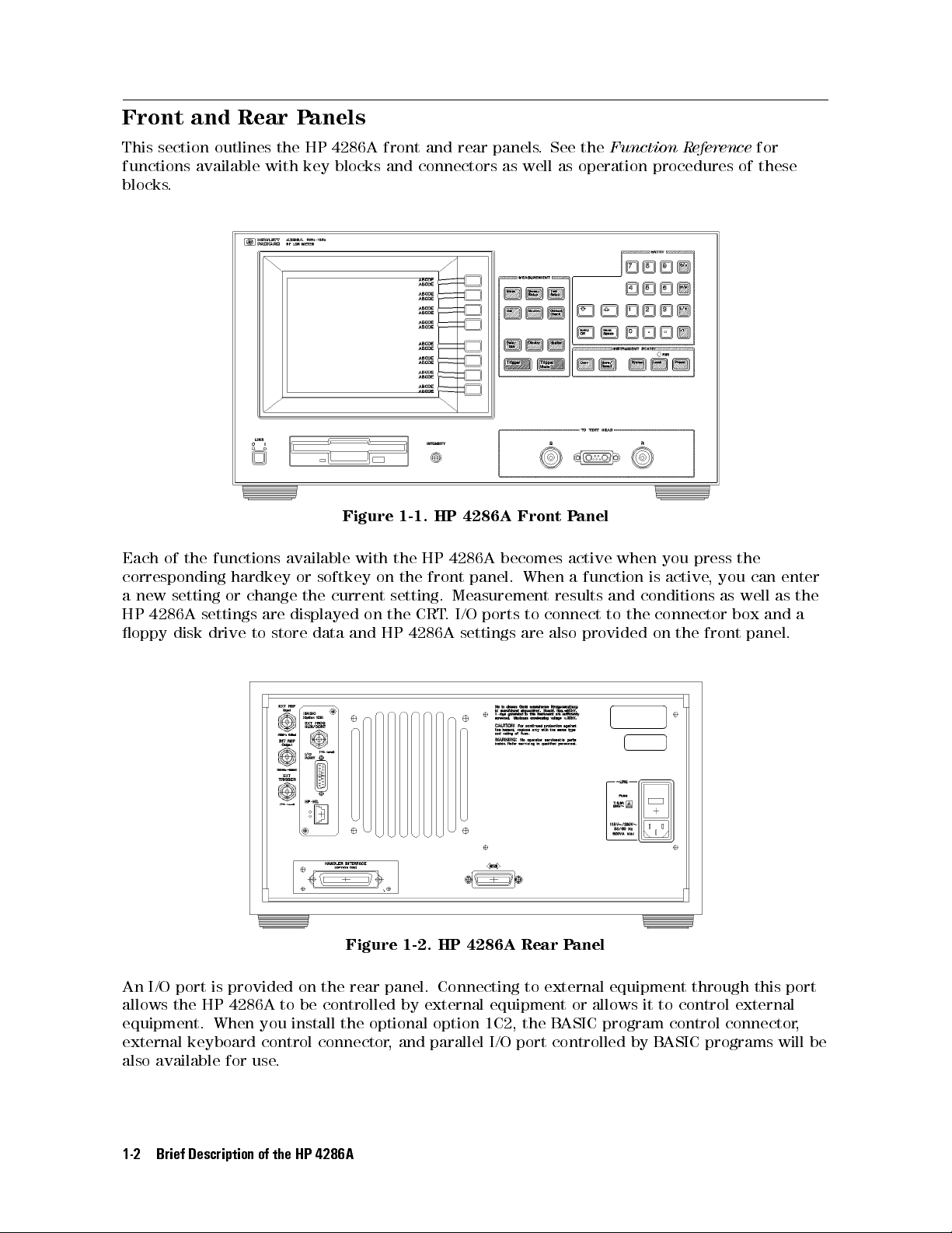
Front and Rear Panels
This section outlines the HP 4286A front and rear panels. See the
functions available with key blocks and connectors as well as operation procedures of these
blocks.
Figure 1-1. HP 4286A Front Panel
Each of the functions available with the HP 4286A becomes active when you press the
corresponding hardkey or softkey on the front panel. When a function is active
a new setting or change the current setting. Measurement results and conditions as well as the
HP 4286A settings are displayed on the CRT. I/O ports to connect to the connector box and a
oppy disk drive to store data and HP 4286A settings are also provided on the front panel.
Function Reference
, you can enter
for
Figure 1-2. HP 4286A Rear Panel
An I/O port is provided on the rear panel. Connecting to external equipment through this port
allows the HP 4286A to be controlled by external equipment or allows it to control external
equipment. When you install the optional option 1C2, the BASIC program control connector,
external keyboard control connector, and parallel I/O port controlled by B
also available for use.
1-2 Brief Description of the HP 4286A
ASIC programs will be

Installation and Set Up Guide
This chapter provides the information necessary for performing an incoming inspection and
setting up your HP 4286A.
Incoming Inspection
2
Warning
Inspect the shipping container for damage. If the shipping container or cushioning material
is damaged, it should be kept until the contents of the shipment have been checked for
completeness and the HP 4286A has been checked mechanically and electrically
of the shipment should be as listed in T
mechanical damage or defect, or if the HP 4286A does not pass the power-on selftests
the nearest Hewlett Packard oce. If the shipping container is damaged, or the cushioning
material shows signs of unusual stress, notify the carrier as well as the Hewlett P
Keep the shipping materials for the carrier's inspection.
The line voltage selector is set at the factory to correspond to the most commonly used line
voltage of the country of destination. If you want to change the line voltage
the Line Voltage Setting" in Appendix B.
To avoid hazardous electrical shock, do not turn on the HP 4286A when
there are signs of shipping damage to any portion of the outer enclosure
(for example, covers, panel, or display)
. The contents
able 2-1 . If the contents are incomplete, if there is
, notify
ackard oce.
, see \Changing
Installation and Set Up Guide 2-1

Table 2-1. Contents
Description HP Part Number
RF LCR meter HP 4286A
Mainframe
Fixture Stand
1
Right Angle Type Test Head with
1-m cable
Documents
User's Guide
Function Reference
Programming Manual
2
3
4
4
4
04286-90001
04286-90002
04291-90007
APC-3.5 to 7mm Adapter 1250-1746
Power Cable
Calibration Kit
4
8120-4753 (See Fig in Spec.)
5
0STermination 04186-85302
0Termination 04186-85300
50 Termination 04286-65006
LOW-LOSS Capacitor 04291-60042
Carrying Case
4
04291-60041
Option 021 only
Straight Angle Type Test Head
04286-60121
with 1-m cable
L-type Coaxial Adapter 1250-1249
Option 022 only
Straight Angle Type Test Head
with 3-m cable
L-type Coaxial Adapter 1250-1249
Option 032 only
Right Angle Type Test Head with
3-m cable
1
Not included when Option 002 is ordered.
2
Not included when Option 031 is ordered.
3
Not included when Option 0B0 is ordered.
4
Accessories are not shown in Figure 2-1 .
5
Not included when Option 001 is ordered.
2-2 Installation and Set Up Guide
04286-60122
04286-60132

Description HP Part Number
Option 004 only
Shorting Device
1.020.5 mm 16191-29005
1.620.8 mm 16191-29006
2.021.25 mm 16191-29007
3.221.6 16191-29008
51 Chip Resistor
1.020.5 mm 5182-0433
1.620.8 mm 5182-0434
2.021.25 mm 5182-0435
3.221.6 mm 5182-0436
Device Case 1540-0692
Option 0BW only
Service Manual
Table 2-1. Contents (continued)
1
04291-90101
Option 1C2 only
Keyboard Template
HP-HIL Keyboard
Keyboard Cable
HP Instrument BASIC User's
Handbook
1
HP Instrument BASIC User's
1
1
1
08751-87111
HP 46021C Option ABA
46020-60001
E2083-90000
04286-90005
Handbook Supplement
1
This item is not shown in Figure 2-1.
Rack Mounting
Rack mounting information is provided with the rack mount kit. If the kit was not ordered
with the HP 4286A as an option, it may be ordered through the nearest Hewlett P
ackard oce.
The part numbers of the rack mount kit are shown in Table 2-2 .
Table 2-2. Rack Mount Kits
Option Description HP Part Number
1CN Handle Kit 5062-3991
1CM Rack Flange Kit 5062-3979
1CP Rack Mount & Handle Kit 5062-3985
Installation and Set Up Guide 2-3

2-4 Installation and Set Up Guide
Figure 2-1. Contents of Package

Power Cable
In accordance with international safety standards, this instrument is equipped with a
three-wire power cable. When connected to an appropriate ac power outlet, this cable grounds
the instrument frame. The type of power cable shipped with each instrument depends on the
country of destination. Refer to Figure 2-2 for the part numbers of the power cables available.
Warning
For protection from electrical shock, the power cable ground must not be
defeated.
The power plug must be plugged into an outlet that provides a protective
earth ground connection.
Installation and Set Up Guide 2-5

2-6 Installation and Set Up Guide
Figure 2-2. Power Cable Supplied

Power Requirements
HP 4286A requires a following power source:
Voltage : 90 to 132 Vac, 198 to 264 Vac
Frequency : 47 to 66 Hz
Power : 500 VA maximum
Ventilation Requirements
To ensure adequate ventilation, make sure that there is adequate clearance of at least 180 mm
behind, 60 mm sides and 15 mm above and below.
Instruction for Cleaning
For cleaning, wipe with soft cloth that is soaked with water and wrung tightly without undue
pressure.
Connecting the Connector Box
The HP 4286A consists of the mainframe, the test head, and the test xture stand. The
test head has a connector box that connects to the mainframe
Figure 2-3. While you connect the connector box to the mainframe
. This connection is shown in
, turn o the HP 4286A.
Installation and Set Up Guide 2-7

Figure 2-3. Connecting the Connector Box to the Mainframe
1. Engage the two type-N connectors (labeledSandR, respectively) and the center connector.
2. Turn the two type-N connectors to tighten the connection.
2-8 Installation and Set Up Guide

Connecting the Test Head
When you connect or replace the test head, turn o the HP 4286A.
1.
Place the test xture stand on a level surface. At this time, make sure that the
hexagonal hole on top of the stand is located in front of the two mounting posts as you look
at the stand. Then, lay the stand on its side.
2.
Allow the test head to pass under the xture stand from the side opposite to yours.
3.
Position the test head such that the connectors of the test head and holes on top of the
xture stand are aligned.
4.
Slightly tighten the two screws on the bottom surface of the xture stand to ensure
that the test head is suciently stable. Press screws to check for correct engagement of
their thread.
5.
Further tighten the screws while holding the test head with your hand to completely
secure the head in place.
6.
Place the xture stand with its bottom surface down.
Connecting the Test Head with L-type Coaxial Adapter
(Option 022 only)
When you connect or replace the test head, turn o the HP 4286A.
1.
Connect Connecting L-type Coaxial Adapter to the Test Head.
2.
Place the test xture stand on a level surface. At this time, make sure that the
hexagonal hole on top of the stand is located in front of the two mounting posts as you look
at the stand. Then, lay the stand on its side
.
3.
Allow the test head to pass under the xture stand from the side opposite to yours.
4.
Position the test head such that the connectors of the L-type Coaxial adapter and holes
on top of the xture stand are aligned.
5.
Slightly tighten the two screws on the bottom surface of the xture stand to ensure
that the test head is suciently stable. Press screws to check for correct engagement of
their thread.
Installation and Set Up Guide 2-9

6.
Further tighten the screws while holding the test head with your hand to completely
secure the head in place.
7.
Place the xture stand with its bottom surface down.
Connecting the APC-3.5 to 7mm Adapter
1. Check that the connector sleeve is fully extended.
2. Connect APC-3.5 to 7mm adapter to the test head connector through the hole on top of the
xture stand.
3. Tighten the adapter nut to secure this adapter in place.
2-10 Installation and Set Up Guide

Connecting a Keyboard (Option 1C2 Only)
When Option 1C2 is installed, an HP-HIL keyboard can be connected to the HP-HIL connector
on the rear panel of the HP 4286A. The HP-HIL keyboard provides an easier way to enter
characters for the le names, display titles, and Instrument BASIC programs. It can also access
the HP 4286A softkey functions by using keyboard function keys.For more information on the
HP-HIL keyboard, see the
HP Instrument BASIC User's Handbook Supplement
that is included
in Option 1C2.
Figure 2-4. Connecting a Keyboard
Installation and Set Up Guide 2-11


Basic Measurement Procedures
This chapter provides a quick start guide of the HP 4286A. New users can quickly become
familiar with the HP 4286A by following these procedures. In this chapter, to help you learn
how to use the HP 4286A, impedance of inductors are measured as examples.
At the end of the quick start procedures, you will have learned how to get the following
measurement results:
Calibration
Setting electrical length of test xture
Correction of test xture
List sweep
3
Basic Measurement Procedures 3-1

Measurement Outline
This chapter describes how to measure the impedance of a 100 nH inductor as an example.
Measurement items and conditions are shown below.
Parameter Ls-Q
Frequency 1, 2, 5, 10, 20, 50, 100, 200, 500, 1000 MHz
OSC level 10 mA
Basic Measurement Flow
Figure 3-1 shows the basic ow for an impedance measurement.
Figure 3-1. Basic Flow for Impedance Measurements
3-2 Basic Measurement Procedures

Required Equipment
To perform all the steps in this quick start, the following equipment is required:
HP 4286A RF LCR meter
Test Head
Fixture Stand
Calibration Kit
Test Fixture
HP 16191A Side Electrode SMD Test Fixture,or
HP 16192A Parallel Electrode SMD Test Fixture,or
HP 16193A Small Side Electrode SMD Test Fixture
Shorting Device Set (Included with HP 16191A, HP 16192A, HP 16193A, and Option 004
Working Standard Set)
Tweezers (Included with HP 16191A, HP 16192A, and HP 16193A)
Device Under Test (DUT) (A chip inductor is used in this guide.)
Figure 3-2. Required Equipment
Basic Measurement Procedures 3-3

1. Power ON
Verify the connector box and the test head are correctly set up before turning ON the
HP 4286A. If they have not been set up, see Chapter 2.
Line Input Receptacle
ACPower cable is connected to this receptacle.
Figure 3-3. Line Input Receptacle and Fuse
Fuse
Use the following fuse:
HP Part Number : 2110-0917
(UL/CSA type, Semi Time Lag, 6.3 A 250 V)
If you need this fuse, contact your nearest Hewlett-Packard Sales and Service Oce.
Steps to turn on the power
1. Verify the power line setting is correct before you turning ON the meter. If necessary, see
\Changing the Line Voltage Setting" in Appendix B.
2. Connect AC power cable to the line input receptacle.
3. Press the LINE switch.
After the power-on self-test (approximately 10 seconds), the installed options and the
connected test head information are displayed.
Note
Only option numbers 1C2 and 001 are displayed at power-on (if they are
installed). Other installed option numbers are listed on the rear panel.
A 30 minute-warm-up period is required to stabilize the HP 4286A after it has been turned ON.
This ensures the HP 4286A its specied measurement accuracy
3-4 Basic Measurement Procedures
.
 Loading...