


MANUAL CHANGES
Agilent 4285A
Precision LCR Meter
Operation Manual
This supplement contains information for correcting manual errors and for adapting the manual to newer instruments that contains
improvements or modifications not doc umented in the existing manual.
To use this supplement
1. Make all ERRATA corrections
2. Make all appropriate serial-num ber-rel ated changes listed below
SERIAL PREFIX OR NUMBER MAKE MANUAL
CHANGES
All 1
New Item
K
SERIAL PREFIX OR NUMBER MAKE MANUAL
CHANGES
MANUAL IDENTIFICATION
Model Number: 4285A
Date Printed: March 2000
Part Number: 04285-90010
ERRATA
CHANGES 1
CHANGE 1 contains the information needed to adapt the 4285A’s manual.
Changed the company name from YOKOGAWA-HEWLETT-PACKARD, LTD., or its abbreviation YHP to Agilent
Technologies Japan, Ltd.
Manual change supplement are revised as often as nec essary to keep manuals as current and acc urate as possible. Agilent Technol ogies
recommends that you peri odi cally request the latest edition of this supplement. Free copies are available from al l Agilent Technologies offi ces.
When requesting copies , quote the m anual ident ific ation inform ation from your supplem ent, or the model number and print date f rom t he titl e
page of the manual.
Date/Div: March 2000/33
Page 1 of 3
PRINTED IN JAPAN
NOTE

The pink sheet titled “CAUTION ON OPERATION”
Change the page title as follows.
CAUTION ON OPERATION
3.HANDLER INTERFACE BOARD (OPTION 201)
Add the following information.
Fuse: Non Time Delay 0.5A 125V
If you need this fuse,contact your nearest Agilent Technologies Sales and Service Office.
MODEL 4284A PRECISION LCR METER OPTION 201 HANDLER INTERFACE
OPERATION NOTE
Page 2-16 Warning
Change the procedure 1 and warning as follows:
1. Disconnect the 4284A’s power cord and allow 1 minute for the internal supply filter capacitors to
discharge.
Dangerous energy/voltage exists when the 4284A is in operation,and for a time after it is
powered down. Allow 1 minute for the internal capacitors to discharge.
Page 2-16
Add the following CAUTION after the procedure 7.
The interface board contains electronic components that can be damaged by static
electricity through electrostatic discharge(ESD).To prevent ESD damage,maintain frequent
contact with any bare sheet metal surface on the chassis. A grounding wrist strap (or similar
device) is useful for this purpose. Handle the board car efully at all times. Avoid touching
electronic components or circuit paths.
MODEL 4284A PRECISION LCR METER OPTION 202 HANDLER INTERFACE
OPERATION NOTE
Page 3-4 Warning
Change the procedure 1 and warning as follows:
1. Disconnect the 4284A’s power cord and allow 1 minute for the internal supply filter capacitors to
discharge.
Dangerous energy/voltage exists when the 4284A is in operation,and for a time after it is
powered down. Allow 1 minute for the internal capacitors to discharge.

Page 3-4
Add the following CAUTION after the procedure 6.
The interface board contains electronic components that can be damaged by static
electricity through electrostatic discharge(ESD).To prevent ESD damage,maintain frequent
contact with any bare sheet metal surface on the chassis. A grounding wrist strap (or similar
device) is useful for this purpose. Handle the board car efully at all times. Avoid touching
electronic components or circuit paths.
MODEL 4284A PRECISION LCR METER OPTION 301 SCANNER INTERFACE
OPERATION NOTE
Page 2-11 Warning
Change the procedure 1 and warning as follows:
Disconnect the power cable from the 4284A and allow 1 minute for the internal capacitors to
discharge.
Dangerous energy/voltage exists when the 4284A is in operation,and for a time after it is
powered down. Allow 1 minute for the internal capacitors to discharge.


MANUAL CHANGES
Agilent 4285A
Precision LCR Meter
Operation Manual
This supplement contains information for correcting manual errors and for adapting the manual to newer instruments that contains
improvements or modifications not doc umented in the existing manual.
To use this supplement
1. Make all ERRATA corrections
2. Make all appropriate serial-num ber-rel ated changes listed below
SERIAL PREFIX OR NUMBER MAKE MANUAL
CHANGES
3041J00276 1
New Item
K
SERIAL PREFIX OR NUMBER MAKE MANUAL
CHANGES
MANUAL IDENTIFICATION
Model Number: 4285A
Date Printed: March 2000
Part Number: 04285-90010
ERRATA
CHANGES 1
When used with the 42851A Precision Q Adapter, make the following changes:
Two system messages are added.
"Warning, Cannot find resonance" (when the tuning capacitor cannot resonate with the DUT)
"Waiting for trigger" (when the 4285A is not triggered)
On the Q CORRECTION page, the SHORT correction function is always set to ON.
On the Q CORRECTION page, the Q-MODE field is added to select between EFFECTIVE Q mode and CIRCUIT
Q mode.
Manual change supplement are revised as often as nec essary to keep manuals as current and acc urate as possible. Agilent Technol ogies
recommends that you peri odi cally request the latest edition of this supplement. Free copies are available from al l Agilent Technologies offi ces.
When requesting copies , quote the m anual ident ific ation inform ation from your supplem ent, or the model number and print date f rom t he titl e
page of the manual.
Date/Div: March 2000/33
Page 1 of 1
PRINTED IN JAPAN
NOTE


CAUTIONS ON OPERATION
1. UNKNOWN (MEASUREMENT) TERMINA LS
Do NOT
NOT apply DC voltage or current to the UNKNOWN terminals. Doing so will damage
NOTNOT
the 4285A. Before you measure a capacitor, be sure the capacitor is fully discharged.
2. MEMORY CARD
Use Agilent Technologies-specified memory cards containing 4285A-specific data only. If
other memory cards are used, the 4285A may be damaged. Non 4285A-specific data
contained on a memory card is not guaranteed, and data may be lost.
To insert a memory card into the MEMORY
facing upward and with the contacts at the slot opening. Insert the card into the slot until
it "clicks" in place.
To remove a memory card from the 4285A, press the UNLOCK button and remove the
card.
Do NOT remove a memory card while LOADing or STORing d ata. Doing so may damage
the memory card and any data stored in the memory card may be lost.
Store memory cards in their furnished card cases when not in use. The card case protects
memory cards from contamination and electrostatic discharge.
Also, store memory cards under the following environmental conditions.
Storage Temperature Range: -30 ℃ to +70 ℃
Storage Humidity Range: 30%. to 85%. (@ +50 ℃)
MEMORY card slot, hold the memory card with the label
MEMORYMEMORY
Do NOT shock or stress memory cards.
When storing or moving your 4285A, be sure the memory card slot is empty (no memory
card inserted).
Do NOT touch the connector contact surface of a memory card and do NOT use chemical
liquids to clean the contacts.
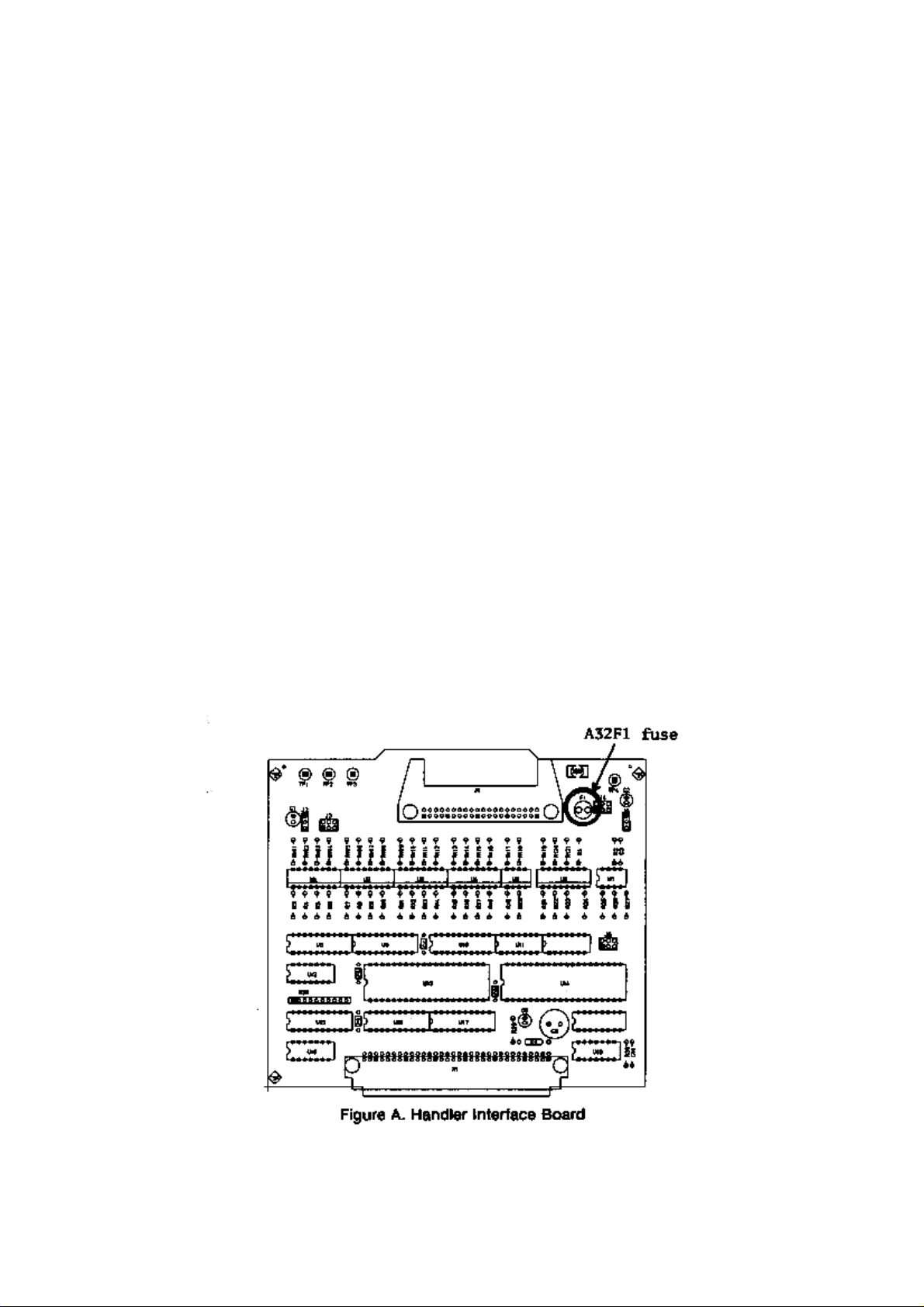
3. HANDLER INTERFACE BOARD (0PTION 201)
If the +5V internal voltage
output
output , a fuse on the handler interface board (A32F1) has blown and must be replaced.
outputoutput
Two replacement fuses are furnished with the 4285A option 201. Additional fuses are
available from Agilent Technologies. Order PN 2110-0046.
Fuse: Mpm Time Delay 0.5A 12.5V
If you need this fuse, contact your nearest Agilent Technologies S ales and S e rv ice O f f ice.
To replace A32F1 , perform the following procedure.
1. To remove the handler interface board (A32), perform proc edu re I th roug h 7
2. Remove A32F1 (indicated in Figure A) from socket and carefully insert the new fuse.
3. Replace the handler interface board, top shield plate, rear feet, and top cover.
+5V internal voltage (pin 16, 17 or 18 of the handler interface connector) is not
+5V internal voltage+5V internal voltage
procedure I through 7 on page
procedure I through 7procedure I through 7
10-26
10-26.
10-2610-26
is not
is notis not
page
pagepage
If the handler interface continues not to output +5V after A32F1 has been replaced,
contact the nearest Agilent Technologies office.


Safety Summary
When you notice any of the unusual conditions listed below, immediately
terminate operation and disconnect the power cable.
Contact your local Agilent Technologies sales representative or
authorized service company for repair of the instrument. If you continue
to operate without repairing the instrument, there is a potential fire or
shock hazard for the operator.
n Instrument operates abnormally.
n Instrument emits abnormal noise, smell, smoke or a spark-like light
during the operation.
n Instrument generates high temperature or electrical shock during
operation.
n Power cable, plug, or receptacle on instrument is damaged.
n Foreign substance or liquid has fallen into the instrument.


Agilent 4285A
PRECISION
LCR
METER
OPERA
SERIAL
This
3009J
read
NUMBERS
manual
.
F
or
\Serial
applies
additional
Number"
TION MANU
directly
important
in
Chapter
to
instruments
information about
1
of this
with serial
Operation Manual.
AL
number prex
serial numbers
,
Agilent Part No. 04285-90010
Printed in JAPAN January 2001
Sixth Edition
Notice
The
information
without
This
notice
document
copyright.
photocopied,
the
prior
written
contained
.
contains
All
rights
reproduced,
consent
in
proprietary
are
reserved.
or
of
this
document
No
translated
the
Agilent
is
information
part
of this
to
another
Technologies
subject to
which
is
document may
language
.
change
protected by
be
without
Agilent
T
echnologies
Component
1-3-2,
Murotani,
Hyogo
,
651-2241
T
est
Japan, Ltd.
PGU-Kobe
Nishi-ku,
Japan
Kobe-shi,
c
Copyright 1990, 1992, 1996, 1997, 2000, 2001
Agilent Technologies Japan, Ltd.
Manual
History
Printing
The
manual printing
edition.
(Minor
not
The printing
corrections
cause the
extensive
June
1990
June
1992
date and
date changes
and
updates which
date to
change.)
technical changes
:
::
::
::
:
:
:
:
:
:
:
:
::
::
::
:
:
:
:
:
:
:
part number
when a
are incorporated
The manual
are incorporated.
:
:
:
:
:
:
:
:
:
:
::
::
::
:
:
:
:
:
:
:
:
:
:
:
:
::
::
indicate its
new edition
part number
::
:
:
:
:
:
:
:
:
::
:
:
:
:
:
:
:
:
:
:
:
:
:
:
:
:
:
current
is printed.
at reprint
changes
:
:
:
First
:
Second
do
when
Edition
Edition
December
September
March
January
2000
2001
1996
1997
:
::
:
::
:
:
:
:
:
:
:
:
:
:
:
:
:
:
:
:
:
:
:
::
::
::
:
:
:
:
:
:
:
:
:
:
:
:
:
Third
Edition
:
::
::
:
:
:
:
F
ourth
Edition
::
:
:
:
:
:
:
:
:
:
:
Fifth
Edition
:
:
:
:
:
:
:
:
:
:
:
:
:
Sixth
Edition
(part
(part
(part
number:
number:
number:
04285-90010)
04285-90010)
04285-90010)
iii
Safety
Summary
The
following general
phases
comply
in
In
intended
The
failure
of operation,
with
this manual
addition it
use of
Agilent
to
comply
safety precautions
service,
these
precautions or
may impair
violates safety
the instrument.
Technologies
with these
and repair
with specic
the protection
standards of
assumes no
requirements.
must be
of this
observed during
instrument. F
WARNINGS
provided by
design, manufacture
liability for
the
all
ailure to
elsewhere
the equipment.
,and
customer's
DO
NOT
Explosive
Keep
DO
A
way
NOT
Note
Note
Ground
Instrument
Operate
In
Atmosphere
From
Circuits
Service
A
djust
Alone
The
An
Live
Or
4285A
DEGREE
LEDs
CLASS
T
must
cable
Do
fumes
o
avoid
complies
in
be
with
not
.
2
this
1
LED
electric
connected
operate
Operation
constitutes
Operating
personnel must
replacement
maintenance
cable
connected.
exist
even
with
disconnect
Do
not
attempt
capable
of
rendering
with
in
IEC1010-1.
product
PRODUCT
shock
earth
blade
the
of
a
denite
and internal
personnel.
Under
the
power
and
internal
INST
ALLA
4285A
are
Class
hazard,
to
a
safety
.
instrument
any
electrical
safety
hazard.
not
adjustments
Do
not
certain
power
cable
discharge
service or
rst
aid and
TION
CA
TEGORY
is
INDOOR
1
in
accordance with
the
instrument
earth
ground
in
the
presence
instrument
remove
instrument
must
replace
components
conditions
removed.
circuits
before
adjustment unless
resuscitation, is
USE
product.
chassis
by
the
of
in
such
be
made
,
dangerous
T
o
avoid
touching
II
and
POLLUTION
IEC825-1.
and
cabinet
supplied
ammable
an
environment
covers
by
with
.
qualied
Component
the
voltages
injuries
,
them.
another person,
present.
power
gasses
power
may
always
or
DO
NOT
Parts
Substitute
Or Modify
Instrument
Dangerous Procedure
Warnings
Warning
iv
Because
install
instrument. Return
of
the
substitute
danger
parts
the
of
introducing
or
perform
instrument
additional
unauthorized
to
a
Agilent
hazards
,
do
modications
T
echnologies
not
to
Sales
the
and
Service Oce for service and repair to ensure that safety features are
maintained.
Warnings
procedures throughout this manual. Instructions contained
, such as
the example below
, precede potentially dangerous
in the
warnings must be followed.
Dangerous voltages, capable of causing death, are present in this
instrument. Use extreme caution when handling, testing, and
adjusting this instrument.
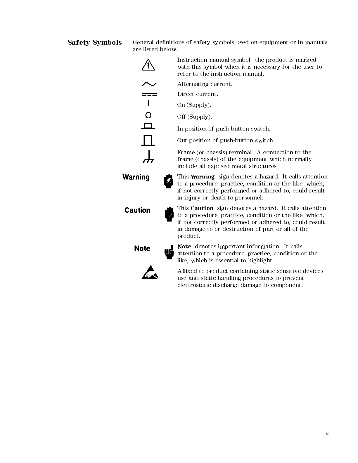
Safety Symbols
General
are
listed below
denitions
.
of
safety symbols
used on
equipment or
in manuals
Instruction
with
this symbol
refer
Alternating
Direct
On
(Supply).
O
(Supply).
In position
Out
position
Frame
frame
include
This
W
to
a
procedure,
if
not
in
injury
This
Caution
to
a
procedure
if
not
in
damage
manual symbol:
to the
instruction manual.
current.
current.
of push-button
(or chassis)
(chassis)
all
exposed
arning
correctly performed
or
death
correctly
to
product.
when it
of
push-button
terminal.
of
the
metal
sign
denotes a
practice,
to
sign
denotes
,
practice
performed
or
destruction
the product
is necessary
switch.
switch.
A
equipment
structures
condition or
or adhered
personnel.
a
hazard.
,
condition
or
of
connection
which
.
hazard. It
the like
It
or
the
adhered
part
or
is marked
for the
to
normally
calls
to,
could result
calls
like
to
,
could
all
of
the
user to
the
attention
,
which,
attention
,
which,
result
Note
denotes
attention
like
Axed
use
to
,
which
to
anti-static
electrostatic
important
a
procedure
is
essential
product
handling
discharge
information.
,
practice
to
highlight.
containing
procedures
damage
,
condition
static
sensitive
to
to
component.
It
calls
prevent
or
the
devices
v

4285A
LCR
Precision
Meter
Documentation
Map
The
documentation for
manuals
purpose
.F
ollowing is
.
The
system
basic
the 4285A
a brief
4285A Getting
setup
and
measurements
has been
description of
Started Guide
initial
power-up
and
explains
separated into
each manual
walks
,
shows
you
how
commonly
several
and its
through
to
make
used
features
.
The
4285A
04285-90010)
GPIB
OPERA
provides
programming
TION
MANU
general
information,
AL
(Agilent
information,
and
in
depth
P
art Number
specications
reference
information.
The
4285A
MAINTENANCE
MANU
AL
(Agilent
P
art
Number 04285-90030) explains how to verify conformance
to published specications
.
,
The
4285A SERVICE MANUAL
(Agilent Part Number
04285-90031) explains how to adjust, troubleshoot, and
repair the instrument. (Furnished Option 915 only.)
vi

How
T
Manual
o
Use
This
This
is the
Operation Manual
This
manual contains
characteristics
control
reference
commands in
.
specications,
,
installation,
nine chapters
for the
4285A Precision
supplemental performance
conguration, operation,
.Use
this manual
LCR Meter
and remote
for the
function
.
General
Information
Product
DISPLA
MEAS
CA
T
ALOG/SYSTEM
CONFIGURA
Chapter
Chapter
1
2
Installation
Chapter 3
Overview
Chapter
Y
FORMA
Chapter
4
T
5
SETUP
Chapter
6
TION
Chapter
1
provides
characteristics
Chapter
kit
know
Chapter
Chapter
and
menukey
Chapter 5
2
provides
installation,
and
do
3
provides
4
provides
measurement
.
provides
condition setup
Chapter
memory
to
the
6
provides
and
system
4
CA
T
ALOG/SYSTEM
the
,
and
other
unpacking,
and
preparation
before
applying
information
detailed
function,
detailed
,
corresponding
detailed
conguration
5
specications
general
information on
initial
information
A
C
power
including
information
corresponding
information
to
the
information
catalog
menukey
.
, supplemental
the 4285A.
inspection,
rack
necessary
.
a
product
for
the
display
to
the
4
for
the
measurement
4
MEAS
for
of
5
SETUP
the
internal/external
the
4285A, corresponding
performance
mount/handle
for
you
overview
format
DISPLA
Y
FORMA
menukey
to
.
5
T
.
Chapter
Measurement
Chapter
Remote
Chapter
Control
7
Basics
8
9
Command Reference
Appendix A
Manual Changes
Chapter
impedance
Chapter
interface
Chapter
7
provides
theory
8
provides
.
9
provides
the
basic
and
measurement
information
detailed
measurement
techniques
to
control
information for
procedure
.
the
4285A using
each
of
the
with
4285A
the
general
the GPIB
GPIB
commands.
Appendix A contains Manual Changes and provides information for
using this manual with an 4285As manufactured before the printing
date
of the manual.
vii

Error
Appendix B
and W
arning
Messages
Appendix
descriptions
B lists
the 4285A's
and solutions
.
error and
warning messages
with brief
Appendix C
Initial
Settings
System
Appendix
Write
Protection
Typeface
Conventions
and
Memory
D
Appendix
status
is
stored
Appendix D
stored data
memory.
Bold
Italics
Computer
C
lists
provides
in
the
the
in
internal
4285A's
4285A's
system
the
procedure
memory
Boldface
F
or
Italic
of
manuals
Italic
when
place
copy
to
type
a
le
Computer
and
initial
memory
type
example:
type
is
type
is
a
name
of
the
lename
a
space
such
as
font
messages
settings
for
write
card
and
is
used
icons
used
and
other
also
or
a
words
means
,
and
file1
is
.
and
.
protecting
internal
when
are
for
emphasis
publications
used
for
variable
in
italics
to
then
.
used
for
functions
EEPROM
a
term
symbols
keyboard
must
.
F
or
type
the
to
type
on-screen
whose
all
of
is
.
and
for
.
entries
be
typed
example:
word
the
prompts
the
dened.
titles
in
copy
name
of
,
Certication
4
HARDKEYS
N
NN
NN
N
N
N
N
SOFTKEYS
5
N
N
N
N
N
N
N
N
N
N
N
N
N
NN
NN
Labeled
are
enclosed
Softkeys
Crystal
keys
in
located
Display
on
the
5
.
4
to
(LCD)
instrument
the
right
are
enclosed
front
of the
panel
Liquid
N
N
in
Agilent Technologies certies that this product met its published
specications at the
Technologies further certies
traceable to the United States
Technology (
nist
facility, or to the calibration
Organization members
time of shipment from the factory
. Agilent
that its calibration measurements are
National Institute of Standards and
), to
the extent allowed by the Institute's calibration
facilities of other International Standards
.
N
N
N
.
viii

W
arranty
This
Agilent T
defects
the
listed
manual,
warranty
or
F
or warranty
service
shipping
shall
Buyer
returned
in material
date
of
shipment, except
in \Components
the warranty
period, Agilent
replace products
facility designated
charges to
pay shipping
shall pay
to Agilent
echnologies instrument
and workmanship
that in
not Covered
shall be
for the
Technologies
which prove
service or
repair
,
to be
this
by Agilent
Agilent T
charges to
all shipping
Technologies
echnologies
return the
charges,
from another
product is
for a
period of
the case
by W
of certain
arranty" in
specied period.
will, at
its option,
defective.
product
T
must
echnologies
and
Agilent
product
duties
,
and
country
warranted against
one year
from
components
Chapter 1
of
During the
be
.
Buyer
to
Buyer
taxes
returned
either
T
echnologies
.
for
repair
to
shall
prepay
However
products
.
this
a
,
Limitation
W
arranty
Exclusive
Remedies
of
Agilent
designated
execute
instrument.
of
error
The
improper
software
operation
or
No
specically
tness
The
remedies
Technologies
by Agilent
its
programming
Agilent
the
instrument,
free
.
foregoing
warranty
or
inadequate
or
interfacing,
outside
improper
other
site
preparation
warranty
disclaims
for
a
particular
remedies provided
.
A
gilent
warrants
T
echnologies
that
instruction
T
echnologies does
or
software
shall
,
not
maintenance
unauthorized
of
the
environmental
or
is
expressed
the
implied
purpose
herein are
T
echnologies shall
its
software
for
use
when
not
or
rmware
apply
to
defects
by
Buyer
modication
specications
maintenance
or
implied.
warranties
.
buyer's
not
be
with
property
warrant
will
.
sole
liable
indirect, special, incidental, or consequential
on contract, tort, or any other legal theory
.
and
rmware
an
instrument
installed
that
be
uninterrupted
resulting
,
Buyer-supplied
or
misuse
for
Agilent
of
Technologies
merchantability
and
exclusive
for
any
the
on
operation
from
,
the
product,
direct,
will
that
damages, whether based
or
and
Assistance
Product maintenance agreements and other customer assistance
agreements are available for Agilent T
echnologies products
.
For any assistance, contact your nearest Agilent Technologies Sales
and Service Oce.Addresses are provided at the back of this manual.
ix


Contents
1.
General
Introduction
Components not
Serial Number
Specications .
Measurement Functions
T
Display
Measurement
Measurement Accuracy Calculation Example . . . . . 1-15
Correction Functions ................ 1-17
Information
.
.
.
.
.
.
.
.
.
.
.
.
.
.
.
.
.
.
Covered
.
.
.
Measurement
Combinations
Mathematical
Equivalent
Ranging .
Trigger
Delay
Time
Measurement
T
est
Cable
Integration
A
veraging
est
Signal
Frequency
Frequency
Signal
Signal
Output
T
j
D
Q
GA
RpAccuracy ...................
RsAccuracy ...................
Basic
N
Cable Length
Temperature F
Example of Ls-Q Accuracy Calculation . . . . . . . 1-15
Zero Open ............ ...... .. 1-17
Zero Short .... ...... ...... .... 1-17
Modes
Normal
Constant
Level
Impedance
est
Signal
Range
Z
j
,
j
Y
j
,
Accuracy
A
ccuracy
Accuracy . . . . . . . . . . .
ccuracy ...........
Accuracy Equations . . . . . . . . . . . . .
Accuracy F
Determine inductance measurement accuracy Ae. 1-15
Determine Q measurement accuracy Qe..... 1-17
P
arameters
of
Functions
Measurement
..
.
.
.
.
.
.
T
erminals
Length
Time
.
.
.
.
.
.
.
A
ccuracy
.
.
.
.
.
.
Level
.
Accuracy
L,
C,
R,
..
.
.
actors . . . . . . . . . . . . . . . .
Factor ...... ...... ...
actor . . . . . . . .
by
W
arranty
.
.
.
.
.
.
.
.
.
.
.
.
.
.
.
.
Measurement
.
.
Circuit
..
.
.
.
.
.
.
.
.
.
.
.
.
.
.
.
.
.
.
.
.
.
.
.
.
.
.
.
.
.
.
.
.
.
.
.
.
.
.
.
.
.
.
.
.
.
.
.
.
.
.
.
.
.
.
.
.
.
.
.
.
.
.
.
.
..
.
.
.
.
..
.
.
.
..
Monitor
.
.
X,
G,
..
.
.
.
.
.
..
and
..
.
.
..
..
B
..
..
.
.
.
.
.
.
.
.
.
.
.
P
arameters
.
.
.
.
.
.
.
.
.
.
.
.
.
.
.
.
.
.
.
.
.
.
.
..
.
.
.
.
.
.
.
.
.
..
..
.
..
.
..
..
.
.
A
ccuracy
.
.
.
.
.
.
.
.
.
.
.
.
.
.
.
.
.
.
.
.
.
.
.
.
.
.
.
.
.
.
.
.
.
.
.
.
.
.
.
.
.
.
.
.
.
.
.
.
.
.
.
.
.
.
.
.
.
.
.
..
..
.
.
.
.
..
.
.
.
.
.
.
.
.
.
.
.
.
.
.
.
.
.
.
.
.
.
.
.
.
.
.
.
.
.
.
.
.
.
.
..
.
.
.
.
.
.
.
.
.
.
.
.
..
.
.
.
.
.
..
..
.
.
.
.
.
.
.
.
.
.
.
.
.
..
..
.
.
..
..
.
.
..
.
.
.
.
.
.
.
.
.
.
.
.
.
.
.
.
.
.
.
.
.
.
.
.
.
.
.
.
.
.........
...... ..
.... ....
..
.
.
..
.
..
.
.
.
.
.
.
.
.
.
.
.
.
..
..
.
.
.
.
.
.
.
.
.
.
.
.
..
.
.
.
.
.
.
.
.
.
.
.
.
.
.
.
.
.
.
.
.
..
. 1-1
.
1-1
. 1-1
1-3
.
1-3
. 1-3
.
1-3
.
1-3
.
1-3
.
1-3
1-3
. 1-3
.
1-4
. 1-4
.
1-4
. 1-4
.
1-4
.
1-4
.
1-4
.
1-4
.
1-4
.
1-4
.
1-4
.
1-5
.
1-5
.
1-6
.
1-6
.
1-9
.
1-9
1-9
1-9
1-10
1-10
1-10
1-10
1-12
1-15
1-15
Contents-1

Load
..
..
..
.
.
.
.
.
.
.
.
.
.
.
..
..
..
List
Sweep .
Comparator
Sorting
Sequential
T
olerance Mode
Bin
Count
List
Sweep
Other
Functions
Store/Load
GPIB
GPIB
Self
T
est
Option
Other
Furnished
A
Power
Operating
Dimensions
W
Display
Supplemental P
Stability ...... ....
Temperature Coecient . . . . . . . . .
Settling Time . . . . . . . . . . .
Input Protection
Measurement Time . . . . . . . . . . . . . . . . . 1-23
Option 001 (Internal DC Bias) .. ...... .... 1-23
DC Bias Settling Time . . . . . . . . . . . . . . . . 1-23
001
DC
Bias
DC
Bias
Options
ccessories
T
est
Fixture
DC
Bias
Memory
GPIB
Handler
201
Scanner
301
Requirements
Line
Voltage
Line
Frequency .
P
ower Consumption
T
emperature .
Humidity
Altitude
eight
.
Capable
Number
Frequency (fm)....... ...... .....
Test Signal Level
Measurement Range
Display Time . . . . . . . . . . . . . . . . . . . 1-23
GPIB Data Output Time . . . . . . . . . . . . . . 1-23
.
.
.
.
.
.
.
.
.
.
.
..
Function .
Modes .
mode .
.
.
Comparator
.
.
.
.
.
.
Interface
Level
Monitor
A
Source
Card
Interconnection
Interface
.
Interface
.
Environment .
.
.
of
of
Functions
.
.
.
(Internal
.
ccessories
A
vailable
/
T
est
.
.
.
.
.
.
.
.
.
.
.
.
.
.
.
.
.
.
.
.
.
.
.
Displaying
Display
erformance Characteristics . . . . . .
.
.
.
.
.
.
.
.
.
.
.
.
.
.
.
.
.
.
.
.
.
.
.
.
.
.
.
.
.
.
.
.
.
.
.
.
.
.
.
.
.
.
.
.
.
.
..
.
.
.
.
.
.
.
.
.
.
.
.
.
.
.
.
.
.
.
.
.
.
.
.
.
.
.
.
.
.
.
.
.
.
.
.
.
.
.
.
.
.
.
.
.
.
.
.
.
.
.
.
..
..
..
DC
Bias)
.
.
.
T
erminal
.
.
.
.
Leads
.
.
.
.
.
.
Cables
Connector
..
..
Connector
.
.
..
.
.
.
.
.
..
.
.
.
.
.
.
.
.
.
.
.
.
.
.
.
.
Digits
.................
..... ..... ...... ..
.
.
.
.
.
.
.
.
.
.
.
..
.
.
.
.
.
.
.
.
.
.
.
.
..
.
.
.
.
.
.
.
..
.
.
.
.
.
.
.
.
.
.
.
.
.
.
.
.
.
.
.
..
..
.
.
.
.
.
..
..
.
.
..
for
Mating
.
.
.
.
.
.
.
for
Mating
.
.
.
.
.
.
.
.
.
.
.
.
.
.
.
.
.
.
.
.
.
.
.
.
.
.
.
.
.
.
.
..
.
.
.
.
.
.
..
.
.
.
.
.
.
.
.
.
.
.
.
.
.
.
.
.
.
.
.
.
.
.
.
.
.
.
.
.
.
.
.
.
.
.
.
.
.
.
.
.
.
.
.
.
.
.
.
.
.
.
.
.
.
.
.
.
.
..
..
.
.
.
..
.
............
...... ...
...... ...... ...
..
..
..
.
.
.
..
.
.
.
..
.
.
.
.
.
.
.
.
..
..
..
.
.
.
.
..
.
.
.
..
.
.
..
..
..
..
..
.
.
.
..
..
.
.
.
.
..
..
..
..
..
.
..
..
..
..
..
..
.
.
.
.
.
..
.
.
.
.
.
..
.
.
..
..
..
.
.
.
with Option
.
.
.
.
.
with
Option
.
.
.
.
.
.
.
.
.
.
.
.
.
.
.
.
.
.
.
.
.
.
.
.
.
.
.
.
.
.
.
.
.
.
.
.
..
..
.
.
.
..
.
.
.
..
..
..
..
.
.
..
..
..
..
.
.
.
.
.
......
. 1-17
..
..
..
..
..
. 1-18
..
. 1-18
.
..
.
.
. 1-18
.
..
.
.
.
.
.
.
.
.
.
.
.
.
.
.
.
.
.
.
.
.
.
.
.
.
.
.
.
.
.
..
..
..
. 1-21
. 1-21
..
.
.
. 1-22
1-17
1-18
1-18
1-18
1-18
1-18
1-18
1-18
1-18
1-18
1-18
1-19
1-19
1-20
1-20
1-20
1-20
1-20
1-20
1-21
1-21
1-21
1-21
1-21
1-21
1-21
1-21
1-21
1-21
1-21
1-21
1-21
1-22
1-22
1-22
1-22
1-22
1-22
1-22
Contents-2

2.
Installation
Incoming
P
ower Requirements
P
ower Cable
Line
Voltage
Line
Voltage
Inspection .
.
.
.
and
Fuse
Selection
.
.
.
.
.
.
.
.
.
.
.
Selection
.
.
.
.
.
.
.
.
.
.
..
..
. 2-1
.
.
.
.
.
.
.
..
..
..
.
.
.
.
.
.
..
..
..
.
.
.
.
.
.
.
.
.
.
..
.
.
.
.
.
.
.
.
.
.
..
2-3
. 2-3
2-5
. 2-5
Fuse Selection
Operation
Electromagnetic
V
entilation Requirements
Instruction
Rack/Handle
Option
Option
Option
3.
Overview
Introduction .
Product
Front
Environment .
907 Handle
Handle
908 Rack
Rack
Mounting
909
Handle
Introduction
P
anel
1
LINE
2
LCD
3
SOFTKEYs
4
MENU
5
CURSOR
6
ENTRY
7
GPIB
8
5
4
LCL
9
4
TRIGGER
A
MEMORY
B
4
DC
BIAS
C
CONTRAST
for Cleaning
Installation .
and
P
Key
..
Compatibility .
.
Installation .
Kit
Flange
.
.
.
Rack
Flange
Rack
Mounting
.
.
.
.
.
.
.
Description
On/O
anel
Keys
Status
Keys
Keys
5
Key
Card
5
Key
.
.
.
.
.
.
.
.
.
.
.
.
Indicator
.
.
.
.
Slot
.
Control
.
.
.
.
.
.
.
.
.
.
.
..
..
.
.
.
.
.
.
.
Kit
.
.
&
Handle
.
.
.
.
.
.
.
.
.
.
.
.
.
.
.
.
.
.
.
.
.
.
and
.
.
Knob
.
.
.
.
.
.
.
.
..
.
.
.
.
.
.
.
.
.
.
.
.
.
.
.
.
.
.
.
.
.
.
.
.
.
.
.
.
.
Kit
.
.
.
.
.
.
.
.
.
.
.
.
.
.
.
.
.
.
.
.
.
.
.
.
.
.
.
.
.
.
.
.
.
.
.
.
.
.
.
.
.
.
.
.
.
.
.
.
.
.
..
UNLOCK
.
.
.
..
.
.
.
.
.
.
.
.
.
.
.
.
.
.
.
.
.
.
.
.
.
.
.
.
.
.
.
.
.
.
.
.
.
.
.
.
.
.
.
.
.
.
.
.
.
.
.
.
.
.
.
.
.
.
.
.
.
.
.
.
.
.
.
.
.
.
.
.
.
.
.
..
Button .
..
.
..
.
.
.
.
.
.
.
.
.
.
.
.
.
.
.
.
.
.
.
.
.
.
.
.
.
.
.
.
.
.
.
.
.
.
..
..
.
.
.
..
.
.
.
.
.
.
..
..
.
.
.
.
.
.
.
.
.
.
.
.
.
.
.
.
.
.
..
.
.
.
.
.
..
.
.
.
.
.
.
.
.
.
.
.
.
..
.
.
.
..
.
.
..
.
.
..
.
.
.
.
.
.
.
.
.
.
.
.
.
.
.
.
.
.
..
.
.
.
.
. 3-1
.
.
.
.
.
. 3-2
.
. 3-2
.
.
.
.
.
.
.
.
.
. 3-3
..
.
.
. 3-3
.
.
.
.
2-5
2-6
2-6
2-7
2-7
2-7
2-7
2-7
2-7
2-7
2-8
2-8
3-1
3-2
3-2
3-2
3-3
3-3
3-3
3-3
3-3
3-3
D
E
Rear
1GPIB Interface Connector
2Interface Connectors . . . . . . . . . . . . . .
3
4EXT TRIGGER Connector . . . . . .
5
6
7
Display .. ...... ...... ..... .... 3-7
Display Area Denition . . . . . . . . . . . . . . . 3-7
Display Page Format Field . . . . . . . . . . . . . 3-7
System Menu Field . . . . . . . . . . . . . . . . 3-7
Comment Field . . . . . . . . . . . . . . . . . . 3-7
Softkey Area . . . . . . . . . . . . . . . . . . . 3-8
Measurement Data/Conditions Area ........ 3-8
UNKNOWN T
FRAME T
P
anel Description
INT DC BIAS MONITOR Connector
LINE Input Receptacle
LINE VOLTAGE SELECTOR . . . . . . . . . .
erminal
LINE Fuse Holder . . . . . . . . . . . .
erminals .
.
.
.
.
.
.
.
.
.
.....
..
.
.
.
.
.
.
.
.
.
.
.
..
..
.
.
.
.
.
.
..
.
...........
..... ..
......
.......
.
.
..
.
.
Contents-3
3-4
3-4
3-5
3-5
3-5
3-5
3-5
3-6
3-6
3-6
Input
Line Area
System
MENU
4
DISPLA
4
MEAS
4
CA
TALOG/SYSTEM
Summary
MEAS
BIN
BIN
LIST
MEAS
CORRECTION
LIMIT
LIST
CA
SYSTEM
CABLE
SELF
Basic
4.
DISPLA
Introduction
MEAS
SYS
N
N
N
N
LOAD
Storing
Loading
N
N
N
N
D.P.
Setting
N
N
N
N
PRINT
Dumping
Printing
NN
N
N
KEY
Locking
BIN
No
COMP
Setting
SYS
Loading
Printing the Measurement Result
Locking Out the Front P
BIN COUNT DISPLA
SYS MENU Field
N
NNNNNNNNNNNNNNNNNNNNNNNNN
COUNT ON
Setting the
Loading or
Printing the Measurement Result ......... 4-17
Locking Out the Front Panel ........... 4-18
LIST SWEEP DISPLAYPage.............. 4-19
MODE Field .................... 4-21
Setting the List Sweep Measurement Mode . . . . . 4-21
SYS MENU Field .................. 4-21
Storing the Control Settings . . . . . . . . . . . . 4-22
Message Area
Keys and
YF
ORMAT
5
SETUP
of
DISPLA
No
.
DISPLA
COUNT
SWEEP
SETUP
T
ABLE
SWEEP
T
ALOG
CONFIG
CORRECTION
TEST
Operation
Y
FORMA
DISPLA
MENU
N
N
N
N
N
N
N
N
N
N
N
N
N
NN
N
N
N
N
N
.
MENU
N
N
N
N
N
N
NN
NN
N
STORE
/
the
NN
N
N
N
N
N
N
N
N
N
N
N
FIX
the
N
N
N
N
N
N
N
N
N
N
N
N
N
DISP
N
N
N
N
N
N
N
N
N
N
N
NN
LOCK
Out
DISPLA
Field
the
Field
N
N
N
the
N
N
N
N
the
out
NN
Field
or
P
ages
(under
.
Y
NN
NN
N
Control
N
N
N
N
N
N
A
Fixed
N
N
N
N
N
N
NN
Softkey
Comparator
Storing
N
NNNNNNNNNNNNNNNNNNNNNNNNN
COUNT OFF
/
Bin Counter ON or OFF
Storing the Control Settings
..
..
.
.
.
.
.
.
.
.
.
.
.
.
.
.
Display
5
..
..
.
5
..
Y
(under
Y
DISPLA
DISPLA
(under
(under
SETUP
SETUP
(under
.
.
T
Menu
.
.
.
P
age
.
N
N
N
Softkeys
Control
N
N
N
N
N
N
N
N
N
D.P.FIX
/
N
N
N
N
N
N
N
N
N
PRINT
/
LCD
the
the
Y
P
age
.
.
.
.
YP
...............
P
age
.
.
.
.
.
.
.
.
.
.
.
.
.
.
.
.
.
.
.
.
.
.
.
.
.
.
.
.
.
.
.
.
.
.
.
.
.
.
.
.
.
.
.
4
DISPLA
Y
F
ORMA
(under
4
CA
(under
4
.
..
..
.
N
N
NN
N
N
N
Decimal
NN
N
N
N
N
N
Screen
Measurement
Front
.
.
the
age ........ ...
4
DISPLA
Y
F
ORMA
Y
(under
Y
(under
4
MEAS
4
MEAS
(under
(under
T
ALOG/SYSTEM
(under
CA
T
ALOG/SYSTEM
.
.
..
..
..
Settings
Settings
N
N
N
N
N
N
N
N
N
N
N
N
N
N
N
N
N
N
N
N
DATA
.
.
P
.
.
.
.
.
..
Control
NNN
4
DISPLA
Y
4
DISPLA
Y
5
)
SETUP
SETUP
4
MEAS
4
MEAS
4
CA
T
ALOG/SYSTEM
4
CA
.
.
.
.
.
.
.
.
.
.
..
.
.
.
.
.
.
.
.
N
Softkeys
P
oint
N
N
N
N
Softkeys
to
the
.
.
.
.
.
..
..
.
.
.
.
.
..
Settings
N
N
N
N
B
N
N
N
N
.
anel
..
Function
anel ...........
Softkeys . . . . . . . . . .
.
5
)
.
SETUP
SETUP
5
)
.
T
ALOG/SYSTEM
5
)
.
.
.
.
.
.
.
.
.
.
.
.
.
..
.
.
.
.
.
.
.
Function
..
Printer
.
.
.
.
.
.
.
.
.
.
.
.
..
..
to
ON
..
...
........
.
.
.
.
.
.
.
.
.
.
.
.
.
.
..
.
.
.
..
..
5
)
.
T
5
)
.
T
F
F
5
ORMA
T
ORMA
T
.
.
.
.
.
.
5
)
.
5
)
.
.
.
.
5
)
.
.
.
.
.
.
.
.
.
.
.
.
.
.
.
.
.
.
.
.
.
.
.
.
.
.
..
.
.
..
.
.
.
.
.
.
.
.
.
.
.
.
..
..
.
.
or
OFF
..
..
..
......
......
.
.
..
..
.
..
..
.
..
..
.
.
.
.
)
.
5
)
.
.
.
.
.
.
.
.
.
.
.
.
5
)
.
.
.
.
.
.
.
.
.
.
.
.
.
.
.
.
.
.
.
.
.
.
.
..
.
.
..
.
.
..
..
.
.
...
...
..
..
..
.
.
.
.
.
.
.
.
.
.
.
.
.
.
.
.
.
.
.
.
.
.
.
.
..
.
.
.
3-8
3-8
3-8
. 3-9
. 3-9
. 3-10
. 3-11
.
3-11
.
3-11
.
3-11
.
3-11
.
3-11
.
3-11
.
3-11
.
3-12
.
3-12
.
3-12
.
3-12
.
3-12
.
3-16
.
4-1
.
4-1
.
4-4
.
4-4
.
4-5
.
4-5
.
4-6
.
4-6
.
4-6
.
4-8
.
4-8
4-9
. 4-9
.
4-10
.
4-12
. 4-12
.
4-13
.
4-13
4-13
4-14
4-15
4-16
4-16
4-16
4-17
Contents-4

Loading
Printing
Locking
5.
MEAS SETUP
Introduction
MEAS
FUNC
Choosing
RANGE
N
N
N
N
N
N
AUTO
N
N
N
N
N
N
HOLD
N
N
N
N
N
N
INCR
N
N
N
N
N
N
DECR
Setting
FREQ
N
N
N
N
N
N
INCR
N
N
N
N
N
N
INCR
N
N
N
N
N
N
DECR
N
NN
NN
NN
DECR
N
N
N
N
N
N
kHz
N
N
N
N
N
N
1kHz
Setting
LEVEL
N
N
N
N
N
N
INCR
N
N
N
N
N
NN
mV
Setting
BIAS
N
N
N
N
N
N
INCR
N
N
N
N
N
N
mV
Setting
INTEG
N
N
N
N
N
N
SHORT
NN
NN
NN
MED
NN
NN
N
N
LONG
Setting the
Comment Field .
NNNNNNNNNNN
COM-MENT
NNNNNNNNNNNNN
[!]
NNNNNNNNNNNNNN
CLEAR LINE
NNN
NNNNNNNNNNNNNNNNNNNNNNNNN
ABORT& EXIT
NNNNNNNNNNNNNNNNN
END INPUT
Entering Comments . . . . . . . . . . . . . . . . 5-14
TRIG Field . . . . . . . . . . . . . . . . . . . . . 5-14
NNNNNNNNNNN
INT
NNNNNNNNNNN
MAN
NNNNNNNNNN
N
EXT
Setting the Trigger Mode .. ...... ..... 5-15
the Control
the Measurement
Out the
Menu
..
.
SETUP
N
N
N
N
N
N
N
N
N
N
N
N
N
N
N
NN
N
N
N
N
N
N
N
N
N
NN
NN
NN
N
N
N
N
N
N
N
N
N
N
N
N
NN
N
,
Field
N
N
N
N
N
N
,
NN
NN
NN
N
N
N
N
N
N
P
age
Field
N
N
N
N
N
N
N
N
N
N
NN
NN
NN
Field
N
N
N
N
N
N
N
N
NN
N
N
N
N
N
N
N
MHz
/
N
N
N
N
N
N
N
N
N
N
V
N
N
N
N
N
N
N
V
Field
NN
N
N
N
Softkey
N
N
N
N
NNNNNNNNNNNNNNN
Softkey................... 5-14
Softkey................... 5-14
Softkey................... 5-14
.
the
Measurement
Field
.
.
Softkey
Softkey
NN
NN
NN
*
Softkey
NN
N
N
N
+
Softkey
the
Measurement
.
.
NN
NN
N
*
N
N
N
NN
1Hz
N
N
N
N
N
1Hz
N
N
N
N
N
+
N
N
N
N
N
N
N
N
N
N
1MHz
/
the
Field
N
N
N
N
N
*
N
N
,
the
N
N
N
N
N
*
N
N
,
the
N
N
N
Softkey
Softkey
Softkey ..............
NNNNNNNNNNNNNNNNNN
NNNNNNNNNNNN
.
N
Softkey
N
N
N
N
N
N
N
Softkey
N
N
N
N
N
N
N
Softkey
N
Softkey
N
N
N
N
Softkeys
N
N
N
N
N
N
N
N
N
N
Softkeys
T
est
.
.
N
N
N
N
N
N
N
N
N
NN
N
N
N
N
DECR
/
N
N
N
N
N
NN
N
A
,
and
Oscillator
.
.
.
N
N
N
N
DECR
and
N
N
N
N
N
N
N
N
N
N
N
N
mA
A
,
DC Bias
..
Integration Time . . . . . . . . . . . .
Softkey . .
Softkey . . . .
NNNNNNN
Softkey .......
Settings .
Result
Front
P
anel
.
.
.
.
.
.
.
.
.
.
.
.
.
.
.
.
.
.
.
.
.
.
.
.
.
.
.
.
.
.
.
.
.
.
.
.
.
.
.
Range
.
.
.
.
.
.
.
.
.
.
.
.
..
..
..
.
.
.
.
.
.
.
Frequency
.
..
.
N
N
N
N
N
N
+
Softkeys
N
N
N
N
mA
.
.
N
N
N
N
N
N
N
N
N
N
N
N
N
N
,
and
..
..
..
.
.
.
...... ...... ..... .
Softkey ..............
.
N
NN
N
Softkeys .
Level
.
.
.
N
N
N
N
N
N
N
+
Softkeys
N
N
N
N
N
A
Softkeys
..
..
..
.
..
..
.
.
.
.
.
.
..............
..
.
.
.
.
.
.
.
.
.
.
.
.
.
.
.
.
.
.
.
.
.
.
.
..
.
.
.
.
.
..
..
.
.
.
.
.
..
..
Function
.
.
.
.
.
.
.
.
..
.
.
.
.
.
.
..
.
.
.
.
.
.
..
.
.
.
.
.
.
.
.
.
..
.
.
.
.
.
.
.
.
.
.
.
.
.
..
.
.
.
.
.
.
.
.
.
.
.
..
..
.
..
..
..
..
..
..
.
.
.
.
.
.
.
.
.
.
..
..
.
.
.
..
..
.
.
.
.
.
.
.
.
.
.
.
.
.
.
.
.
.
.
.
.
.
.
.
.
.
.
.
.
.
.
.
.
.
..
.
.
.
.
.
.
.
.
.
.
.
.
.
.
.
..
.
.
.
.
.
.
.
.
.
.
.
.
.
.
.
.
.
.
.
.
.
..
.
.
.
.
.
.
.
.
.
.
.
.
.
.
.
.
.
.
.
.
.
.
.
.
.
.
.
.
.
.
.
.
.
.
.
.
.
.
.
.
.
.
..
..
...... .....
........
.
.
.
..
..
..
.
..
..
..
.
.
..
.
.
.
.
.
.
.
.
.
.
..
.
.
.
.
.
.
....
.
.
.
.
..
..
..
..
.
.
..
..
..
.
.
.
.
.
..
.
.
.
.
.
.
.
.
.
.
..
.
.
.
.
.
.
.
.
.
.
.
.
.
.
..
.
.
.
.
.
.
.
.
..
.
4-22
.
4-22
. 4-24
5-1
5-1
5-4
.
5-4
5-5
5-6
. 5-6
.
5-6
.
5-6
.
5-6
5-7
.
5-7
.
5-7
.
5-7
.
5-7
.
5-7
.
5-8
.
5-8
.
5-9
.
5-9
.
5-9
.
5-9
.
5-10
.
5-11
5-11
.
5-11
.
5-12
.
5-12
.
5-12
. 5-12
5-12
5-13
5-13
5-13
5-13
5-13
5-13
Contents-5
ALC
Field .
Setting
MON
Field .
N
NN
NN
N
N
N
N
N
N
N
N
N
N
V
BIAS
NN
N
N
N
N
N
N
N
N
N
N
N
N
N
I
BIAS
Setting the
AVG
Field .
NN
NN
NN
NN
N
N
N
N
N
N
N
INCR
Setting
DELA
Y
Field
N
N
N
N
N
N
N
N
N
N
NN
NN
msec
Setting
Vm/Im
DEV
REF
SYS
CORRECTION
OPEN
SHORT Field . . . . . . . .
FREQ1{7 Fields
Fields
Setting
A/B
N
N
N
N
N
N
N
N
N
N
N
N
N
N
N
1
ABS
N
N
N
N
N
N
N
N
N
N
N
1
%
Softkey
N
N
N
N
N
N
N
N
N
N
N
OFF
Softkey
A/B
N
N
N
N
N
N
N
N
N
N
NN
NN
NN
MEA-SURE
P
erforming the
MENU Field
N
N
N
NN
NN
N
N
N
N
N
N
N
LOAD
/
N
N
N
N
N
N
N
N
N
N
N
N
N
N
N
CLEAR
Resetting
P
age
N
N
N
N
N
N
N
N
N
N
N
N
N
N
NN
PRINT
Dumping
N
N
N
N
N
N
N
N
N
N
N
N
NN
N
SYSTEM
Resetting
Field .
N
NN
NN
NN
N
ON
Softkey .
N
NN
N
N
N
N
N
N
N
N
OFF
Softkey
N
N
N
N
N
N
N
N
N
N
N
N
N
N
N
MEAS
N
N
N
N
N
N
N
N
N
N
NN
NN
NN
ABORT
P
erforming
NNNNNNNN
ON
Softkey .... ....
NNNNNNN
NNNN
OFF
Softkey . . . . . . . . . . . . . . . . . . .
NNNNNNNNNNNNNNNNNNNNN
MEAS SHORT
NNNNNNNNNN
NNNNNNN
ABORT
Performing the SHORT Correction . . . . .
NNNNNNNN
ON
Softkey .... ...... ...... ... 5-34
NNNNNNNNNNN
OFF
Softkey . . . . . . . . . . . . . . . . . . . 5-34
NNNNNNNNNNNNNNNNNNNNNNNNNNNNN
MEAS OPEN
NNNNNNNNNNNNNNNNNNNNNNNNNNNNNNNN
MEAS SHORT
NNNNNNNNNNNNNNNNNNNNNNNNNNNNN
MEAS LOAD
the A
N
NN
NN
Softkey
NN
NN
N
Softkey
N
N
N
N
N
*
and
the
and
the
the
Fields
NN
Softkey
Fields
N
N
N
N
N
N
N
N
N
N
N
N
NN
NN
N
N
N
STORE
N
N
N
N
N
N
N
NN
NN
SETUP
the
.
N
N
N
N
N
N
N
N
N
DISP
the
N
N
N
N
N
N
N
N
N
N
RESET
the
N
NN
NN
NN
NN
N
OPEN
N
Softkey
NNNNNNNNNNN
Softkey
..
..
.
.
.
.
.
.
.
utomatic
.
.
DC Bias
..
NN
NN
NN
NN
DECR
A
veraging
.
.
N
N
N
N
N
N
N
N
N
N
N
sec
Softkeys
Delay
.
.
T
est
Signal
.
.
.
N
Softkey
Deviation Measurement
N
N
N
N
N
N
N
Softkeys .
N
N
N
N
N
N
N
N
N
Softkey
Control
.
.
N
N
N
N
N
N
N
Softkey
MEAS
N
N
N
N
N
N
N
N
N
N
N
N
N
4285A
P
age
..
.
N
N
N
N
Softkey
the
OPEN
Softkey..........
Softkey ........ ...... . 5-34
Softkey............... 5-34
Softkey ........ ...... . 5-35
Level
Control
.
.
.
.
.
.
.
.
.
.
.
.
.
.
.
.
.
.
.
.
.
.
.
.
.
Monitor Mode
.
.
.
.
.
.
.
.
N
N
N
N
N
N
N
N
N
N
N
N
+
Softkeys .
Rate
.
.
.
..
..
Time
.
.
.
.
.
.
.
.
Softkey
.
..
.
.
..................
.........
.
.
.
Level
.
.
.
.
.
.
.
.
.
.
.
.
.
..
.
.
.
.
.
Settings
.
.
.
.
SETUP
.
.
.
.
.
.
.
.
.
.
.
.
.
.
..
Correction
.
.
.
.
.
.
.
.
..
.
.
.
.
.
.
.
.
.
..
.
.
.
.
.
..
.
.
.
.
..
.
.
.
.
.
.
.
.
.
.
.
Monitor
.
.
.
.
.
.
.
.
.
..
.
.
.
.
..
.
.
..
..
.
.
.
.
.
.
.
.
.
.
.
on
the
.
.
..
.
.
.
.
P
age
.
.
.
.
.
..
..
.
.
.
.
.
.
.
.
.
.
.
.
.
.
.
.
..
..
............
...... .....
.
.
.
.
..
..
. 5-16
Function
..
..
.
.
.
.
.
..
..
..
.
.
.
..
.
..
..
.
.
.
.
.
..
.
.
.
.
.
.
Function
.
.
.
..
..
..
.
.
.
..
.
.
.
..
.
.
.
.
.
.
.
.
.
MEAS
.
.
.
.
.
..
.
.
.
..
..
..
.
.
.
.
.
.
.
.
.
.
.
.
.
.
.
.
..
.
.
..
.........
.
..
..
.
.
..
..
..
.
.
.
.
.
.
.
.
.
.
.
..
.
.
.
.
.
..
..
.
.
.
.
..
..
.
.
..
..
..
..
.
.
.
.
.
.
.
.
.
.
.
.
.
.
.
.
.
.
.
.
.
.
.
.
.
.
.
.
.
.
.
SETUP
.
.
.
.
.
.
.
.
..
.
.
.
.
.
.
.
.
.
.
.
.
.
.
.
.
.
.
.
.
.
.
.
..
..
..
..
..
.
.
.
.....
....
.
.
. 5-19
..
. 5-19
.
.
.
. 5-20
.
.
.
.
.
.
.
..
..
.
.
. 5-21
.
.
.
.
.
.
.
.
.
.
.
.
.
.
.
.
.
.
.
.
.
.
.
.
.
.
.
.
.
.
.
.
.
. 5-30
..
.
.
.
.
5-19
5-19
5-19
5-20
5-20
5-20
5-20
5-20
5-21
5-21
5-21
5-22
5-22
5-22
5-22
5-22
5-23
5-23
5-23
5-24
5-24
5-24
5-25
5-25
5-26
5-29
5-30
5-30
5-31
5-31
5-32
5-32
5-32
5-33
5-33
5-33
5-34
Contents-6
 Loading...